EP3218650B1 - Heating installation - Google Patents
Heating installation Download PDFInfo
- Publication number
- EP3218650B1 EP3218650B1 EP15793766.5A EP15793766A EP3218650B1 EP 3218650 B1 EP3218650 B1 EP 3218650B1 EP 15793766 A EP15793766 A EP 15793766A EP 3218650 B1 EP3218650 B1 EP 3218650B1
- Authority
- EP
- European Patent Office
- Prior art keywords
- medium
- heat pump
- circuit
- evaporator
- heat
- Prior art date
- Legal status (The legal status is an assumption and is not a legal conclusion. Google has not performed a legal analysis and makes no representation as to the accuracy of the status listed.)
- Active
Links
Images



Classifications
-
- F—MECHANICAL ENGINEERING; LIGHTING; HEATING; WEAPONS; BLASTING
- F24—HEATING; RANGES; VENTILATING
- F24D—DOMESTIC- OR SPACE-HEATING SYSTEMS, e.g. CENTRAL HEATING SYSTEMS; DOMESTIC HOT-WATER SUPPLY SYSTEMS; ELEMENTS OR COMPONENTS THEREFOR
- F24D19/00—Details
- F24D19/10—Arrangement or mounting of control or safety devices
- F24D19/1006—Arrangement or mounting of control or safety devices for water heating systems
- F24D19/1066—Arrangement or mounting of control or safety devices for water heating systems for the combination of central heating and domestic hot water
- F24D19/1072—Arrangement or mounting of control or safety devices for water heating systems for the combination of central heating and domestic hot water the system uses a heat pump
-
- F—MECHANICAL ENGINEERING; LIGHTING; HEATING; WEAPONS; BLASTING
- F24—HEATING; RANGES; VENTILATING
- F24D—DOMESTIC- OR SPACE-HEATING SYSTEMS, e.g. CENTRAL HEATING SYSTEMS; DOMESTIC HOT-WATER SUPPLY SYSTEMS; ELEMENTS OR COMPONENTS THEREFOR
- F24D3/00—Hot-water central heating systems
- F24D3/02—Hot-water central heating systems with forced circulation, e.g. by pumps
-
- F—MECHANICAL ENGINEERING; LIGHTING; HEATING; WEAPONS; BLASTING
- F24—HEATING; RANGES; VENTILATING
- F24D—DOMESTIC- OR SPACE-HEATING SYSTEMS, e.g. CENTRAL HEATING SYSTEMS; DOMESTIC HOT-WATER SUPPLY SYSTEMS; ELEMENTS OR COMPONENTS THEREFOR
- F24D3/00—Hot-water central heating systems
- F24D3/08—Hot-water central heating systems in combination with systems for domestic hot-water supply
-
- F—MECHANICAL ENGINEERING; LIGHTING; HEATING; WEAPONS; BLASTING
- F24—HEATING; RANGES; VENTILATING
- F24D—DOMESTIC- OR SPACE-HEATING SYSTEMS, e.g. CENTRAL HEATING SYSTEMS; DOMESTIC HOT-WATER SUPPLY SYSTEMS; ELEMENTS OR COMPONENTS THEREFOR
- F24D3/00—Hot-water central heating systems
- F24D3/18—Hot-water central heating systems using heat pumps
-
- F—MECHANICAL ENGINEERING; LIGHTING; HEATING; WEAPONS; BLASTING
- F25—REFRIGERATION OR COOLING; COMBINED HEATING AND REFRIGERATION SYSTEMS; HEAT PUMP SYSTEMS; MANUFACTURE OR STORAGE OF ICE; LIQUEFACTION SOLIDIFICATION OF GASES
- F25B—REFRIGERATION MACHINES, PLANTS OR SYSTEMS; COMBINED HEATING AND REFRIGERATION SYSTEMS; HEAT PUMP SYSTEMS
- F25B25/00—Machines, plants or systems, using a combination of modes of operation covered by two or more of the groups F25B1/00 - F25B23/00
- F25B25/005—Machines, plants or systems, using a combination of modes of operation covered by two or more of the groups F25B1/00 - F25B23/00 using primary and secondary systems
-
- F—MECHANICAL ENGINEERING; LIGHTING; HEATING; WEAPONS; BLASTING
- F25—REFRIGERATION OR COOLING; COMBINED HEATING AND REFRIGERATION SYSTEMS; HEAT PUMP SYSTEMS; MANUFACTURE OR STORAGE OF ICE; LIQUEFACTION SOLIDIFICATION OF GASES
- F25B—REFRIGERATION MACHINES, PLANTS OR SYSTEMS; COMBINED HEATING AND REFRIGERATION SYSTEMS; HEAT PUMP SYSTEMS
- F25B29/00—Combined heating and refrigeration systems, e.g. operating alternately or simultaneously
- F25B29/003—Combined heating and refrigeration systems, e.g. operating alternately or simultaneously of the compression type system
-
- F—MECHANICAL ENGINEERING; LIGHTING; HEATING; WEAPONS; BLASTING
- F25—REFRIGERATION OR COOLING; COMBINED HEATING AND REFRIGERATION SYSTEMS; HEAT PUMP SYSTEMS; MANUFACTURE OR STORAGE OF ICE; LIQUEFACTION SOLIDIFICATION OF GASES
- F25B—REFRIGERATION MACHINES, PLANTS OR SYSTEMS; COMBINED HEATING AND REFRIGERATION SYSTEMS; HEAT PUMP SYSTEMS
- F25B30/00—Heat pumps
- F25B30/02—Heat pumps of the compression type
-
- F—MECHANICAL ENGINEERING; LIGHTING; HEATING; WEAPONS; BLASTING
- F25—REFRIGERATION OR COOLING; COMBINED HEATING AND REFRIGERATION SYSTEMS; HEAT PUMP SYSTEMS; MANUFACTURE OR STORAGE OF ICE; LIQUEFACTION SOLIDIFICATION OF GASES
- F25B—REFRIGERATION MACHINES, PLANTS OR SYSTEMS; COMBINED HEATING AND REFRIGERATION SYSTEMS; HEAT PUMP SYSTEMS
- F25B7/00—Compression machines, plants or systems, with cascade operation, i.e. with two or more circuits, the heat from the condenser of one circuit being absorbed by the evaporator of the next circuit
-
- F—MECHANICAL ENGINEERING; LIGHTING; HEATING; WEAPONS; BLASTING
- F24—HEATING; RANGES; VENTILATING
- F24D—DOMESTIC- OR SPACE-HEATING SYSTEMS, e.g. CENTRAL HEATING SYSTEMS; DOMESTIC HOT-WATER SUPPLY SYSTEMS; ELEMENTS OR COMPONENTS THEREFOR
- F24D2200/00—Heat sources or energy sources
- F24D2200/12—Heat pump
-
- F—MECHANICAL ENGINEERING; LIGHTING; HEATING; WEAPONS; BLASTING
- F24—HEATING; RANGES; VENTILATING
- F24D—DOMESTIC- OR SPACE-HEATING SYSTEMS, e.g. CENTRAL HEATING SYSTEMS; DOMESTIC HOT-WATER SUPPLY SYSTEMS; ELEMENTS OR COMPONENTS THEREFOR
- F24D2200/00—Heat sources or energy sources
- F24D2200/12—Heat pump
- F24D2200/123—Compression type heat pumps
-
- F—MECHANICAL ENGINEERING; LIGHTING; HEATING; WEAPONS; BLASTING
- F25—REFRIGERATION OR COOLING; COMBINED HEATING AND REFRIGERATION SYSTEMS; HEAT PUMP SYSTEMS; MANUFACTURE OR STORAGE OF ICE; LIQUEFACTION SOLIDIFICATION OF GASES
- F25B—REFRIGERATION MACHINES, PLANTS OR SYSTEMS; COMBINED HEATING AND REFRIGERATION SYSTEMS; HEAT PUMP SYSTEMS
- F25B2339/00—Details of evaporators; Details of condensers
- F25B2339/04—Details of condensers
- F25B2339/047—Water-cooled condensers
-
- F—MECHANICAL ENGINEERING; LIGHTING; HEATING; WEAPONS; BLASTING
- F25—REFRIGERATION OR COOLING; COMBINED HEATING AND REFRIGERATION SYSTEMS; HEAT PUMP SYSTEMS; MANUFACTURE OR STORAGE OF ICE; LIQUEFACTION SOLIDIFICATION OF GASES
- F25B—REFRIGERATION MACHINES, PLANTS OR SYSTEMS; COMBINED HEATING AND REFRIGERATION SYSTEMS; HEAT PUMP SYSTEMS
- F25B2400/00—Component parts or details not otherwise provided for in this subclass
- F25B2400/06—Several compression cycles arranged in parallel
-
- F—MECHANICAL ENGINEERING; LIGHTING; HEATING; WEAPONS; BLASTING
- F25—REFRIGERATION OR COOLING; COMBINED HEATING AND REFRIGERATION SYSTEMS; HEAT PUMP SYSTEMS; MANUFACTURE OR STORAGE OF ICE; LIQUEFACTION SOLIDIFICATION OF GASES
- F25B—REFRIGERATION MACHINES, PLANTS OR SYSTEMS; COMBINED HEATING AND REFRIGERATION SYSTEMS; HEAT PUMP SYSTEMS
- F25B6/00—Compression machines, plants or systems, with several condenser circuits
- F25B6/04—Compression machines, plants or systems, with several condenser circuits arranged in series
-
- Y—GENERAL TAGGING OF NEW TECHNOLOGICAL DEVELOPMENTS; GENERAL TAGGING OF CROSS-SECTIONAL TECHNOLOGIES SPANNING OVER SEVERAL SECTIONS OF THE IPC; TECHNICAL SUBJECTS COVERED BY FORMER USPC CROSS-REFERENCE ART COLLECTIONS [XRACs] AND DIGESTS
- Y02—TECHNOLOGIES OR APPLICATIONS FOR MITIGATION OR ADAPTATION AGAINST CLIMATE CHANGE
- Y02B—CLIMATE CHANGE MITIGATION TECHNOLOGIES RELATED TO BUILDINGS, e.g. HOUSING, HOUSE APPLIANCES OR RELATED END-USER APPLICATIONS
- Y02B30/00—Energy efficient heating, ventilation or air conditioning [HVAC]
- Y02B30/12—Hot water central heating systems using heat pumps
Definitions
- the present invention relates to a heating installation according to the preamble of claim 1.
- a heating installation according to the preamble of claim 1 is previously known from the patent document WO 2006/057594 A1 .
- the heating installation disclosed in WO 2006/057594 A1 comprises a first heat pump for heating a medium in a first circuit.
- a heat exchanger connected between the condenser and the expansion valve of the first heat pump is used for transferring heat from the working medium of the heat pump to a medium in a second circuit, wherein a second heat pump is arranged for heating a medium by absorbing heat energy from the medium in the second circuit.
- the object of the present invention is to achieve a further development of a heating installation of the type described above in order to provide a heating installation with a configuration which in at least some aspect offers an advantage as compared to this previously known heating installation.
- the heating installation according to the invention comprises:
- the first accumulator tank is connected to an evaporator of the third heat pump in order to allow medium to circulate between the first accumulator tank and the evaporator of the third heat pump so that heat exchange between the medium in the second circuit and a working medium of the third heat pump is possible via the evaporator of the third heat pump.
- the above-mentioned heat exchanger constitutes a so-called subcooler of the first heat pump and is used in order to transfer heat form the working medium of the first heat pump to the medium in the second circuit, wherein the second heat pump is arranged to utilize heat energy from the medium in the second circuit in order to satisfy desired heating demands.
- surplus heat of the working medium of the first heat pump may be utilized for suitable heating purposes instead of being wasted, and an increase of the efficiency of the first heat pump is obtained.
- the third heat pump can be used in co-operation with the first accumulator tank in order to ensure that the temperature of the medium in the second circuit has been lowered to a temperature within a predetermined temperature interval before this medium is returned to said heat exchanger. Furthermore, rapid changes in the temperature of the medium return to the heat exchanger are prevented by means of the first accumulator tank. Therefore, the operation of the second heat pump does not have to be adapted focused on the attainment of a given temperature reduction of the medium in the second circuit.
- the operation of the second heat pump may instead be adapted with primary focus on an efficient energy recovery.
- the second heat pump may consequently be operated in an essentially optimal manner with respect to energy recovery.
- the solution according to the invention makes it possible to ensure in a simple manner, by means of the third heat pump and the first accumulator tank, to ensure a desired cooling of the medium in the second circuit before the medium is conveyed into said heat exchanger, which in its turn makes it possible for the heat exchanger to achieve an efficient subcooling of the working medium of the first heat pump, at the same time as heat energy of the medium in the second circuit can be utilized in an essentially optimal manner by means of the second heat pump.
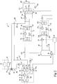
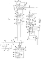
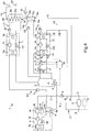
- FIGs 1-6 Different embodiments of a heating installation 1 according to the invention are schematically illustrated in Figs 1-6 .
- the illustrated heating installations are configured for heating a house or other building and tap hot-water associated therewith.
- the heating installation according to the invention may also be configured for satisfying other types of heating demands.
- the heating installation 1 comprises a first circuit C1 and a second circuit C2, each of which containing a liquid medium, such as for instance water.
- a circulation pump 2 is arranged in the first circuit C1 for circulating the medium in this circuit.
- a circulation pump 3 is also arranged in the second circuit C2 for circulating the medium in this circuit.
- the heating installation 1 comprises a first heat pump 4 which is arranged for heating the medium in the first circuit C1, for instance by utilizing geothermal heat, ground heat and/or solar heat.
- the first heat pump 4 comprises an evaporator 4a, a condenser 4b, a compressor 4c and an expansion valve 4d, preferably an electromechanical expansion valve.
- the working medium of the heat pump absorbs heat energy via the evaporator 4a.
- Work is added via the compressor 4c, whereby the pressure and the temperature of the working medium is increased.
- heat energy is then emitted to the medium in the first circuit C1 by heat exchange and the working medium of the heat pump is then returned to the evaporator 4a via the expansion valve 4d, the pressure and the temperature of the working medium being lowered when passing the expansion valve.
- the heat pump 4 has its output side connected to the first circuit C1 so that heat exchange between the working medium of the heat pump and the medium in the first circuit C1 is possible via the condenser 4b of the heat pump.
- An outlet 4e of the condenser 4b of the first heat pump is by means of a feeding conduit 5 connected to the inlet 6 of one or more heat emitting devices 7. These devices 7 are used for heating a further medium, in this case the air within the building, and are for instance constituted by conventional radiators to be operated with hot-water or other medium.
- the outlet 8 of the heat emitting devices is by means of a return conduit 9 connected to an inlet 4f of the condenser 4b of the first heat pump.
- the heating installation 1 further comprises a heat exchanger 10 which is arranged in the second circuit C2 and connected between the condenser 4b and the expansion valve 4d of the first heat pump 4 in order to transfer heat from the working medium of the first heat pump 4 to the medium in the second circuit C2.
- the condensate of the first heat pump 4 is consequently utilized in order to supply heat energy to the medium in the second circuit C2.
- the heat exchanger 10 constitutes a so-called subcooler of the first heat pump 4.
- the heat exchanger 10 has a primary circuit through which the working medium of the first heat pump 4 is arranged to flow, and a secondary circuit which, via an inlet 10a and an outlet 10b of this secondary circuit, is connected to the second circuit C2 in order to allow the medium in the second circuit C2 to flow through the secondary circuit.
- the heating installation 1 further comprises a second heat pump 11 which is arranged for heating a medium by absorbing heat energy from the medium in the second circuit C2.
- the second heat pump 11 comprises an evaporator 11a, a condenser 11b, a compressor 11c and an expansion valve 11d, preferably an electromechanical expansion valve.
- the working medium of the second heat pump absorbs heat energy via the evaporator 11a.
- Work is added via the compressor 11c, whereby the pressure and the temperature of the working medium of the second heat pump is increased.
- the condenser 11b heat energy is then emitted to another medium by heat exchange and the working medium of the second heat pump is then returned to the evaporator 11a via the expansion valve 11d, the pressure and the temperature of the working medium being lowered when passing the expansion valve.
- the second heat pump 11 has its input side connected to the second circuit C2 so that heat exchange between the medium in the second circuit C2 and the working medium of the second heat pump is possible via the evaporator 11a of the second heat pump.
- the second heat pump 11 is arranged to emit heat energy for final heating of tap hot-water and/or in order to give an addition of heat to the medium in the first circuit C1.
- the second heat pump 11 could as an alternative be arranged to emit heat energy for another heating purpose.
- the heating installation 1 comprises a first accumulator tank 12 arranged in the second circuit C2 for accumulating the medium in the second circuit, wherein this accumulator tank 12 is arranged in the second circuit C2 downstream of the second heat pump 11 as seen in a flow direction from an outlet 10b of said heat exchanger 10 to an inlet 10a thereof.
- the heating installation 1 also comprises a third heat pump 13 arranged for heating a medium by absorbing heat energy from the medium in the second circuit C2.
- the third heat pump 13 comprises an evaporator 13a, a condenser 13b, a compressor 13c and an expansion valve 13d, preferably an electromechanical expansion valve.
- the first accumulator tank 12 is connected to the evaporator 13a in order to allow medium to circulate between the first accumulator tank 12 and this evaporator 13a.
- the working medium of the third heat pump absorbs heat energy via the evaporator 13a.
- An electronic control device 14 is configured to control the circulation of medium between the first accumulator tank 12 and the evaporator 13a of the third heat pump in dependence on one or more predetermined control variables.
- the electronic control device 14 is configured to control said circulation in dependence on a temperature value T1 representing the temperature of the medium flowing in the second circuit C2 from an outlet 15 of the first accumulator tank 12 in the direction towards the inlet 10a of the heat exchanger 10, wherein this temperature value T1 is established by means of a temperature sensor 16 which is connected to the electronic control device 14.
- the heating installation 1 further comprises a second circulation pump 17 which is arranged in a conduit between the first accumulator tank 12 and the evaporator 13a of the third heat pump in order to achieve circulation of medium between the first accumulator tank 12 and the evaporator 13a of the third heat pump.
- the electronic control device 14 is configured to control the circulation of medium between the first accumulator tank 12 and the evaporator 13a of the third heat pump by controlling this circulation pump 17.
- the second circuit C2 comprises a feed conduit 18 which is connected to an inlet 13g of the evaporator 13a of the third heat pump and through which medium from the first accumulator tank 12 can be conveyed into the evaporator 13a of the third heat pump, and a return conduit 19 which is connected to an outlet 13h of the evaporator 13a of the third heat pump and through which medium can be conveyed back to the first accumulator tank 12 from the evaporator 13a of the third heat pump.
- the second circuit C2 further comprises a shunt conduit 20, via which the return conduit 19 is connected to the feed conduit 18 in order to allow medium flowing via the feed conduit 18 from the first accumulator tank 12 in the direction towards said inlet 13g of the evaporator 13a of the third heat pump to be mixed with medium which is returned via the shunt conduit 20 from said outlet 13h to said inlet 13g of the evaporator 13a of the third heat pump.
- the mixing proportion between medium flowing from the first accumulator tank 12 through the feed conduit 18 and medium supplied to the feed conduit 18 from the shunt conduit 20 is regulated by means of a regulating valve 21.
- the regulating valve 21 is arranged in the feed conduit 18, but it could alternatively be arranged in the return conduit 19.
- the regulating valve 21 is controlled by means of the electronic control device 14 in dependence on a temperature value T2 representing the temperature of the medium flowing into the evaporator 13a of the third heat pump via said inlet 13g and/or a temperature value T3 representing the temperature of the medium flowing out of the evaporator 13a of the third heat pump via said outlet 13h.
- These temperature values T2, T3 are established by means of temperature sensors 22, 23 which are connected to the electronic control device 14.
- the electronic control device 14 is capable of ensuring that the temperature of the medium flowing into the evaporator 13a of the third heat pump via the feed conduit 18 is kept at a desired level.
- the evaporator 11a of the second heat pump and the first accumulator tank 12 are arranged in the second circuit C2 in series with each other and in series with the heat exchanger 10.
- a second accumulator tank 25 is also arranged in the second circuit C2 for accumulating the medium in the second circuit, wherein this second accumulator tank 25 is arranged in the second circuit C2 in series with an upstream of the first accumulator tank 12 as seen in the above-mentioned flow direction.
- the second accumulator tank 25 is connected to the second heat pump 11 in order to allow medium to circulate between the second accumulator tank 25 and the evaporator 11a of the second heat pump.
- the second circuit C2 comprises a feed conduit 28 which is connected to an inlet 11g of the evaporator 11a of the second heat pump and through which medium from the second accumulator tank 25 can be conveyed into the evaporator 11a of the second heat pump, and a return conduit 29 which is connected to an outlet 11h of the evaporator 11a of the second heat pump and through which medium can be conveyed back to the second accumulator tank 25 from the evaporator 11a of the second heat pump.
- the second circuit C2 further comprises a shunt conduit 30, via which the return conduit 29 is connected to the feed conduit 28 in order to allow medium flowing via the feed conduit 28 from the second accumulator tank 25 in the direction towards said inlet 11g of the evaporator 11a of the second heat pump to be mixed with medium which is returned via the shunt conduit 30 from said outlet 11h to said inlet 11g of the evaporator 11a of the second heat pump.
- the mixing proportion between medium flowing from the second accumulator tank 25 through the feed conduit 28 and medium supplied to the feed conduit 28 from the shunt conduit 30 is regulated by means of a regulating valve 31.
- the regulating valve 31 is arranged in the feed conduit 28, but it could alternatively be arranged in the return conduit 29.
- the regulating valve 31 is controlled by means of the electronic control device 14 in dependence on a temperature value T4 representing the temperature of the medium flowing into the evaporator 11a of the second heat pump via said inlet 11g and/or a temperature value T5 representing the temperature of the medium flowing out of the evaporator 11a of the second heat pump via said outlet 11h.
- These temperature values T4, T5 are established by means of temperature sensors 32, 33 which are connected to the electronic control device 14.
- the electronic control device 14 is capable of ensuring that the temperature of the medium flowing into the evaporator 11a of the second heat pump via the feed conduit 28 is kept at a predetermined level.
- the circulation of medium between the second accumulator tank 25 and the evaporator 11a of the second heat pump is achieved by means of a circulation pump 34, which in the embodiments illustrated in Figs 4 and 5 is arranged in the feed conduit 28.
- This circulation pump 34 could alternatively be arranged in the return conduit 29.
- the heating installation 1 comprises a third circuit C3, which contains a liquid medium, such as for instance water.
- a circulation pump 35 is arranged in the third circuit C3 for circulating the medium in this circuit.
- the second heat pump 11 has its output side connected to the third circuit C3 so that heat exchange between the working medium of the second heat pump 11 and the medium in the third circuit C3 is possible via the condenser 11b of the second heat pump.
- a heat emitting device 36 is arranged in the third circuit C3 for heating tap hot-water by transfer of heat from the medium in the third circuit C3 to water which is intended to be heated in order to provide tap hot-water.
- the tap hot-water final-heated by the heat emitting device 36 is stored in an accumulator tank 37 in the following denominated third accumulator tank.
- tap hot-water circuit C4 tap hot-water is conveyed from an outlet 38 of the third accumulator tank 37 to one or more tapping points 39, which for instance may be provided with hot-water taps.
- Tap hot-water that has passed the tapping points 39 without being tapped is conveyed back to the third accumulator tank 37.
- a circulation pump 40 is arranged in the tap hot-water circuit C4 for circulating the medium in this circuit. In the embodiments illustrated in Figs 1-5 , no preheating of the tap hot-water takes place, and the third accumulator tank 37 is consequently arranged to receive cold water directly from a cold water supply line 41 in this case.
- the heat emitting device 36 comprises a heating coil 36a which is arranged in the third accumulator tank 37 and through which the medium in the third circuit C3 is allowed to flow in order to transfer heat from the medium in the third circuit C3 to the water in the third accumulator tank 37.
- the heating installation 1 comprises a further heat exchanger 43, in the following denominated second heat exchanger, which is arranged in the second circuit C2 in order to transfer heat from the medium in the second circuit C2 to another medium.
- the second heat exchanger 43 is connected to the first accumulator tank 12 in order to allow medium to circulate between the first accumulator tank 12 and this heat exchanger 43.
- the circulation of medium between the first accumulator tank 12 and the second heat exchanger 43 is achieved by means of a circulation pump 44.
- the second heat exchanger 43 is connected to the water supply line 41 upstream of the third accumulator tank 37 and is consequently used for preheating the tap hot-water.
- the second heat exchanger 43 has a primary circuit which, via an inlet 45a and an outlet 45b of this primary circuit, is connected to the second circuit C2 in order to allow medium in the second circuit C2 to flow through the primary circuit, and a secondary circuit which, via an inlet 46a and an outlet 46b of this secondary circuit, is connected to the water supply line 41 in order to allow water in the water supply line 41 to flow through this secondary circuit.
- the third heat pump 13 has its output side connected to the first circuit C1 so that heat exchange between the working medium of the third heat pump 13 and the medium in the first circuit C1 is possible via the condenser 13b of the third heat pump.
- the third heat pump 13 is consequently arranged to utilize heat energy from the medium in the second circuit C2 in order to give an addition of heat to the medium in the first circuit C1 and thereby contribute to the heating of the air in the building in question via the heat emitting devices 7 arranged in the first circuit C1.
- An outlet 13e of the condenser 13b of the third heat pump is connected to the first circuit C1 via a first connecting conduit 47, and an inlet 13f of the condenser 13b of the third heat pump is connected to the first circuit C1 via a second connecting conduit 48.
- Medium may flow from the first circuit C1 to the condenser 13b of the third heat pump via the second connecting conduit 48, through the condenser 13b of the third heat pump while absorbing heat from the working medium of the third heat pump 13, and then back to the first circuit C1 via the first connecting conduit 47.
- the first connecting conduit 47 is connected to the first circuit C1 at a first point P1 located in the feeding conduit 5
- the second connecting conduit 48 is connected to the first circuit C1 at a second point P2 located in the feeding conduit 5 upstream of said first point P1.
- a circulation pump 51 is arranged in the first connecting conduit 47. This circulation pump 51 could alternatively be arranged in the second connecting conduit 48.
- the second heat pump 11 has its output side connected to the first circuit C1 so that heat exchange between the working medium of the second heat pump 11 and the medium in the first circuit C1 is possible via the condenser 11b of the second heat pump.
- the second heat pump 11 is consequently arranged to utilize heat energy from the medium in the second circuit C2 in order to give an addition of heat to the medium in the first circuit C1 and thereby contribute to the heating of the air in the building in question via the heat emitting devices 7 arranged in the first circuit C1.
- An outlet 11e of the condenser 11b of the second heat pump is connected to the first circuit C1 via a first connecting conduit 57, and an inlet 11f of the condenser 11b of the second heat pump is connected to the first circuit C1 via a second connecting conduit 58.
- Medium may flow from the first circuit C1 to the condenser 11b of the second heat pump via the second connecting conduit 58, through the condenser 11b of the second heat pump while absorbing heat from the working medium of the second heat pump 11, and then back to the first circuit C1 via the first connecting conduit 57.
- the first connecting conduit 57 is connected to the first circuit C1 at a first point P1 located in the feeding conduit 5, whereas the second connecting conduit 58 is connected to the first circuit C1 at a second point P2 located in the feeding conduit 5 upstream of said first point P1.
- the first connecting conduit 57 is connected to the first circuit C1 via a regulating valve 59, by means of which the flow through the connecting conduits 57, 58 can be regulated. This regulating valve 59 is consequently arranged at said first point P1.
- a non-return valve 56 is arranged in the third circuit C3.
Landscapes
- Engineering & Computer Science (AREA)
- Physics & Mathematics (AREA)
- Thermal Sciences (AREA)
- Mechanical Engineering (AREA)
- General Engineering & Computer Science (AREA)
- Chemical & Material Sciences (AREA)
- Combustion & Propulsion (AREA)
- Water Supply & Treatment (AREA)
- Steam Or Hot-Water Central Heating Systems (AREA)
- Heat-Pump Type And Storage Water Heaters (AREA)
Description
- The present invention relates to a heating installation according to the preamble of
claim 1. - A heating installation according to the preamble of
claim 1 is previously known from the patent documentWO 2006/057594 A1 . The heating installation disclosed inWO 2006/057594 A1 comprises a first heat pump for heating a medium in a first circuit. A heat exchanger connected between the condenser and the expansion valve of the first heat pump is used for transferring heat from the working medium of the heat pump to a medium in a second circuit, wherein a second heat pump is arranged for heating a medium by absorbing heat energy from the medium in the second circuit. - The object of the present invention is to achieve a further development of a heating installation of the type described above in order to provide a heating installation with a configuration which in at least some aspect offers an advantage as compared to this previously known heating installation.
- According to the invention, said object is achieved by means of a heating installation having the features defined in
claim 1. The dependent claims 2-13 define preferred embodiments of the invention. - The heating installation according to the invention comprises:
- a first circuit containing a medium;
- a second circuit containing a medium;
- a first heat pump arranged for heating the medium in the first circuit;
- a heat exchanger which is arranged in the second circuit and which is connected between a condenser and an expansion valve of the first heat pump in order to transfer heat from a working medium of the first heat pump to the medium in the second circuit;
- a second heat pump arranged for heating a medium by absorbing heat energy from the medium in the second circuit, wherein the second heat pump has its input side connected to the second circuit so that heat exchange between the medium in the second circuit and a working medium of the second heat pump is possible via an evaporator of the second heat pump;
- an accumulator tank, here denominated first accumulator tank, which is arranged in the second circuit for accumulating the medium in the second circuit, wherein this accumulator tank is arranged in the second circuit downstream of the second heat pump as seen in a flow direction from an outlet of said heat exchanger to an inlet thereof; and
- a third heat pump arranged for heating a medium by absorbing heat energy from the medium in the second circuit.
- The first accumulator tank is connected to an evaporator of the third heat pump in order to allow medium to circulate between the first accumulator tank and the evaporator of the third heat pump so that heat exchange between the medium in the second circuit and a working medium of the third heat pump is possible via the evaporator of the third heat pump.
- The above-mentioned heat exchanger constitutes a so-called subcooler of the first heat pump and is used in order to transfer heat form the working medium of the first heat pump to the medium in the second circuit, wherein the second heat pump is arranged to utilize heat energy from the medium in the second circuit in order to satisfy desired heating demands. Hereby, surplus heat of the working medium of the first heat pump may be utilized for suitable heating purposes instead of being wasted, and an increase of the efficiency of the first heat pump is obtained.
- In the heating installation according to the invention, the third heat pump can be used in co-operation with the first accumulator tank in order to ensure that the temperature of the medium in the second circuit has been lowered to a temperature within a predetermined temperature interval before this medium is returned to said heat exchanger. Furthermore, rapid changes in the temperature of the medium return to the heat exchanger are prevented by means of the first accumulator tank. Therefore, the operation of the second heat pump does not have to be adapted focused on the attainment of a given temperature reduction of the medium in the second circuit. The operation of the second heat pump may instead be adapted with primary focus on an efficient energy recovery. The second heat pump may consequently be operated in an essentially optimal manner with respect to energy recovery. The solution according to the invention makes it possible to ensure in a simple manner, by means of the third heat pump and the first accumulator tank, to ensure a desired cooling of the medium in the second circuit before the medium is conveyed into said heat exchanger, which in its turn makes it possible for the heat exchanger to achieve an efficient subcooling of the working medium of the first heat pump, at the same time as heat energy of the medium in the second circuit can be utilized in an essentially optimal manner by means of the second heat pump.
- Other favourable features of the heating installation according to the invention will appear from the dependent claims and the description following below.
- The invention will in the following be more closely described by means of embodiment examples, with reference to the appended drawings. It is shown in:
- Fig 1
- a schematic illustration of a heating installation according to a first embodiment of the present invention,
- Fig 2
- a schematic illustration of a heating installation according to a second embodiment of the invention,
- Fig 3
- a schematic illustration of a heating installation according to a third embodiment of the invention,
- Fig 4
- a schematic illustration of a heating installation according to a fourth embodiment of the invention,
- Fig 5
- a schematic illustration of a heating installation according to a fifth embodiment of the invention, and
- Fig 6
- a schematic illustration of a heating installation according to a sixth embodiment of the invention.
- Different embodiments of a
heating installation 1 according to the invention are schematically illustrated inFigs 1-6 . The illustrated heating installations are configured for heating a house or other building and tap hot-water associated therewith. However, the heating installation according to the invention may also be configured for satisfying other types of heating demands. - The
heating installation 1 according to the invention comprises a first circuit C1 and a second circuit C2, each of which containing a liquid medium, such as for instance water. Acirculation pump 2 is arranged in the first circuit C1 for circulating the medium in this circuit. Acirculation pump 3 is also arranged in the second circuit C2 for circulating the medium in this circuit. - The
heating installation 1 comprises afirst heat pump 4 which is arranged for heating the medium in the first circuit C1, for instance by utilizing geothermal heat, ground heat and/or solar heat. Thefirst heat pump 4 comprises anevaporator 4a, acondenser 4b, a compressor 4c and anexpansion valve 4d, preferably an electromechanical expansion valve. By heat exchange with a medium in a circuit, here not shown, connected to theevaporator 4a, the working medium of the heat pump absorbs heat energy via theevaporator 4a. Work is added via the compressor 4c, whereby the pressure and the temperature of the working medium is increased. In thecondenser 4b, heat energy is then emitted to the medium in the first circuit C1 by heat exchange and the working medium of the heat pump is then returned to theevaporator 4a via theexpansion valve 4d, the pressure and the temperature of the working medium being lowered when passing the expansion valve. Theheat pump 4 has its output side connected to the first circuit C1 so that heat exchange between the working medium of the heat pump and the medium in the first circuit C1 is possible via thecondenser 4b of the heat pump. - An outlet 4e of the
condenser 4b of the first heat pump is by means of afeeding conduit 5 connected to theinlet 6 of one or moreheat emitting devices 7. Thesedevices 7 are used for heating a further medium, in this case the air within the building, and are for instance constituted by conventional radiators to be operated with hot-water or other medium. Theoutlet 8 of the heat emitting devices is by means of areturn conduit 9 connected to aninlet 4f of thecondenser 4b of the first heat pump. - The
heating installation 1 according to the invention further comprises aheat exchanger 10 which is arranged in the second circuit C2 and connected between thecondenser 4b and theexpansion valve 4d of thefirst heat pump 4 in order to transfer heat from the working medium of thefirst heat pump 4 to the medium in the second circuit C2. According to the invention, the condensate of thefirst heat pump 4 is consequently utilized in order to supply heat energy to the medium in the second circuit C2. Theheat exchanger 10 constitutes a so-called subcooler of thefirst heat pump 4. Theheat exchanger 10 has a primary circuit through which the working medium of thefirst heat pump 4 is arranged to flow, and a secondary circuit which, via aninlet 10a and anoutlet 10b of this secondary circuit, is connected to the second circuit C2 in order to allow the medium in the second circuit C2 to flow through the secondary circuit. - The
heating installation 1 according to the invention further comprises asecond heat pump 11 which is arranged for heating a medium by absorbing heat energy from the medium in the second circuit C2. Thesecond heat pump 11 comprises an evaporator 11a, a condenser 11b, acompressor 11c and an expansion valve 11d, preferably an electromechanical expansion valve. By heat exchange with the medium in the second circuit C2 connected to the evaporator 11a, the working medium of the second heat pump absorbs heat energy via the evaporator 11a. Work is added via thecompressor 11c, whereby the pressure and the temperature of the working medium of the second heat pump is increased. In the condenser 11b, heat energy is then emitted to another medium by heat exchange and the working medium of the second heat pump is then returned to the evaporator 11a via the expansion valve 11d, the pressure and the temperature of the working medium being lowered when passing the expansion valve. Thesecond heat pump 11 has its input side connected to the second circuit C2 so that heat exchange between the medium in the second circuit C2 and the working medium of the second heat pump is possible via the evaporator 11a of the second heat pump. In the illustrated embodiments, thesecond heat pump 11 is arranged to emit heat energy for final heating of tap hot-water and/or in order to give an addition of heat to the medium in the first circuit C1. However, thesecond heat pump 11 could as an alternative be arranged to emit heat energy for another heating purpose. - The
heating installation 1 comprises afirst accumulator tank 12 arranged in the second circuit C2 for accumulating the medium in the second circuit, wherein thisaccumulator tank 12 is arranged in the second circuit C2 downstream of thesecond heat pump 11 as seen in a flow direction from anoutlet 10b of saidheat exchanger 10 to aninlet 10a thereof. - The
heating installation 1 according to the invention also comprises athird heat pump 13 arranged for heating a medium by absorbing heat energy from the medium in the second circuit C2. Thethird heat pump 13 comprises anevaporator 13a, acondenser 13b, acompressor 13c and anexpansion valve 13d, preferably an electromechanical expansion valve. Thefirst accumulator tank 12 is connected to theevaporator 13a in order to allow medium to circulate between thefirst accumulator tank 12 and thisevaporator 13a. By heat exchange with the medium in the second circuit C2 connected to theevaporator 13a, the working medium of the third heat pump absorbs heat energy via theevaporator 13a. Work is added via thecompressor 13c, whereby the pressure and the temperature of the working medium of the third heat pump is increased. In thecondenser 13b, heat energy is then emitted to another medium by heat exchange and the working medium of the third heat pump is then returned to theevaporator 13a via theexpansion valve 13d, the pressure and the temperature of the working medium being lowered when passing the expansion valve. - An
electronic control device 14 is configured to control the circulation of medium between thefirst accumulator tank 12 and the evaporator 13a of the third heat pump in dependence on one or more predetermined control variables. In the illustrated embodiments, theelectronic control device 14 is configured to control said circulation in dependence on a temperature value T1 representing the temperature of the medium flowing in the second circuit C2 from anoutlet 15 of thefirst accumulator tank 12 in the direction towards theinlet 10a of theheat exchanger 10, wherein this temperature value T1 is established by means of atemperature sensor 16 which is connected to theelectronic control device 14. - The
heating installation 1 further comprises asecond circulation pump 17 which is arranged in a conduit between thefirst accumulator tank 12 and the evaporator 13a of the third heat pump in order to achieve circulation of medium between thefirst accumulator tank 12 and the evaporator 13a of the third heat pump. - The
electronic control device 14 is configured to control the circulation of medium between thefirst accumulator tank 12 and the evaporator 13a of the third heat pump by controlling thiscirculation pump 17. - The second circuit C2 comprises a
feed conduit 18 which is connected to an inlet 13g of the evaporator 13a of the third heat pump and through which medium from thefirst accumulator tank 12 can be conveyed into theevaporator 13a of the third heat pump, and areturn conduit 19 which is connected to anoutlet 13h of the evaporator 13a of the third heat pump and through which medium can be conveyed back to thefirst accumulator tank 12 from the evaporator 13a of the third heat pump. In the embodiments illustrated inFigs 3-6 , the second circuit C2 further comprises ashunt conduit 20, via which thereturn conduit 19 is connected to thefeed conduit 18 in order to allow medium flowing via thefeed conduit 18 from thefirst accumulator tank 12 in the direction towards said inlet 13g of the evaporator 13a of the third heat pump to be mixed with medium which is returned via theshunt conduit 20 from saidoutlet 13h to said inlet 13g of the evaporator 13a of the third heat pump. The mixing proportion between medium flowing from thefirst accumulator tank 12 through thefeed conduit 18 and medium supplied to thefeed conduit 18 from theshunt conduit 20 is regulated by means of a regulatingvalve 21. In the embodiments illustrated inFigs 3-6 , the regulatingvalve 21 is arranged in thefeed conduit 18, but it could alternatively be arranged in thereturn conduit 19. The regulatingvalve 21 is controlled by means of theelectronic control device 14 in dependence on a temperature value T2 representing the temperature of the medium flowing into theevaporator 13a of the third heat pump via said inlet 13g and/or a temperature value T3 representing the temperature of the medium flowing out of the evaporator 13a of the third heat pump via saidoutlet 13h. These temperature values T2, T3 are established by means oftemperature sensors electronic control device 14. By means of the regulatingvalve 21, theelectronic control device 14 is capable of ensuring that the temperature of the medium flowing into theevaporator 13a of the third heat pump via thefeed conduit 18 is kept at a desired level. - In the embodiments illustrated in
Figs 1-3 and6 , the evaporator 11a of the second heat pump and thefirst accumulator tank 12 are arranged in the second circuit C2 in series with each other and in series with theheat exchanger 10. - In the embodiments illustrated in
Figs 4 and5 , asecond accumulator tank 25 is also arranged in the second circuit C2 for accumulating the medium in the second circuit, wherein thissecond accumulator tank 25 is arranged in the second circuit C2 in series with an upstream of thefirst accumulator tank 12 as seen in the above-mentioned flow direction. Thesecond accumulator tank 25 is connected to thesecond heat pump 11 in order to allow medium to circulate between thesecond accumulator tank 25 and the evaporator 11a of the second heat pump. The second circuit C2 comprises afeed conduit 28 which is connected to aninlet 11g of the evaporator 11a of the second heat pump and through which medium from thesecond accumulator tank 25 can be conveyed into the evaporator 11a of the second heat pump, and areturn conduit 29 which is connected to anoutlet 11h of the evaporator 11a of the second heat pump and through which medium can be conveyed back to thesecond accumulator tank 25 from the evaporator 11a of the second heat pump. The second circuit C2 further comprises ashunt conduit 30, via which thereturn conduit 29 is connected to thefeed conduit 28 in order to allow medium flowing via thefeed conduit 28 from thesecond accumulator tank 25 in the direction towards saidinlet 11g of the evaporator 11a of the second heat pump to be mixed with medium which is returned via theshunt conduit 30 from saidoutlet 11h to saidinlet 11g of the evaporator 11a of the second heat pump. The mixing proportion between medium flowing from thesecond accumulator tank 25 through thefeed conduit 28 and medium supplied to thefeed conduit 28 from theshunt conduit 30 is regulated by means of a regulatingvalve 31. In the embodiments illustrated inFigs 4 and5 , the regulatingvalve 31 is arranged in thefeed conduit 28, but it could alternatively be arranged in thereturn conduit 29. The regulatingvalve 31 is controlled by means of theelectronic control device 14 in dependence on a temperature value T4 representing the temperature of the medium flowing into the evaporator 11a of the second heat pump via saidinlet 11g and/or a temperature value T5 representing the temperature of the medium flowing out of the evaporator 11a of the second heat pump via saidoutlet 11h. These temperature values T4, T5 are established by means oftemperature sensors electronic control device 14. By means of the regulatingvalve 31, theelectronic control device 14 is capable of ensuring that the temperature of the medium flowing into the evaporator 11a of the second heat pump via thefeed conduit 28 is kept at a predetermined level. - The circulation of medium between the
second accumulator tank 25 and the evaporator 11a of the second heat pump is achieved by means of acirculation pump 34, which in the embodiments illustrated inFigs 4 and5 is arranged in thefeed conduit 28. Thiscirculation pump 34 could alternatively be arranged in thereturn conduit 29. - In the illustrated embodiments, the
heating installation 1 comprises a third circuit C3, which contains a liquid medium, such as for instance water. Acirculation pump 35 is arranged in the third circuit C3 for circulating the medium in this circuit. Thesecond heat pump 11 has its output side connected to the third circuit C3 so that heat exchange between the working medium of thesecond heat pump 11 and the medium in the third circuit C3 is possible via the condenser 11b of the second heat pump. Aheat emitting device 36 is arranged in the third circuit C3 for heating tap hot-water by transfer of heat from the medium in the third circuit C3 to water which is intended to be heated in order to provide tap hot-water. In the illustrated embodiments, the tap hot-water final-heated by theheat emitting device 36 is stored in anaccumulator tank 37 in the following denominated third accumulator tank. Via a tap hot-water circuit C4, tap hot-water is conveyed from anoutlet 38 of thethird accumulator tank 37 to one or more tapping points 39, which for instance may be provided with hot-water taps. Tap hot-water that has passed the tapping points 39 without being tapped is conveyed back to thethird accumulator tank 37. Acirculation pump 40 is arranged in the tap hot-water circuit C4 for circulating the medium in this circuit. In the embodiments illustrated inFigs 1-5 , no preheating of the tap hot-water takes place, and thethird accumulator tank 37 is consequently arranged to receive cold water directly from a coldwater supply line 41 in this case. - In the illustrated embodiments, the
heat emitting device 36 comprises a heating coil 36a which is arranged in thethird accumulator tank 37 and through which the medium in the third circuit C3 is allowed to flow in order to transfer heat from the medium in the third circuit C3 to the water in thethird accumulator tank 37. - In the embodiment illustrated in
Fig 6 , theheating installation 1 comprises afurther heat exchanger 43, in the following denominated second heat exchanger, which is arranged in the second circuit C2 in order to transfer heat from the medium in the second circuit C2 to another medium. Thesecond heat exchanger 43 is connected to thefirst accumulator tank 12 in order to allow medium to circulate between thefirst accumulator tank 12 and thisheat exchanger 43. The circulation of medium between thefirst accumulator tank 12 and thesecond heat exchanger 43 is achieved by means of acirculation pump 44. In the illustrated example, thesecond heat exchanger 43 is connected to thewater supply line 41 upstream of thethird accumulator tank 37 and is consequently used for preheating the tap hot-water. Thesecond heat exchanger 43 has a primary circuit which, via an inlet 45a and an outlet 45b of this primary circuit, is connected to the second circuit C2 in order to allow medium in the second circuit C2 to flow through the primary circuit, and a secondary circuit which, via aninlet 46a and anoutlet 46b of this secondary circuit, is connected to thewater supply line 41 in order to allow water in thewater supply line 41 to flow through this secondary circuit. - In the embodiments illustrated in
Figs 5 and6 , thethird heat pump 13 has its output side connected to the first circuit C1 so that heat exchange between the working medium of thethird heat pump 13 and the medium in the first circuit C1 is possible via thecondenser 13b of the third heat pump. In these embodiments, thethird heat pump 13 is consequently arranged to utilize heat energy from the medium in the second circuit C2 in order to give an addition of heat to the medium in the first circuit C1 and thereby contribute to the heating of the air in the building in question via theheat emitting devices 7 arranged in the first circuit C1. Anoutlet 13e of thecondenser 13b of the third heat pump is connected to the first circuit C1 via a first connectingconduit 47, and aninlet 13f of thecondenser 13b of the third heat pump is connected to the first circuit C1 via a second connectingconduit 48. Medium may flow from the first circuit C1 to thecondenser 13b of the third heat pump via the second connectingconduit 48, through thecondenser 13b of the third heat pump while absorbing heat from the working medium of thethird heat pump 13, and then back to the first circuit C1 via the first connectingconduit 47. In the embodiments illustrated inFigs 5 and6 , the first connectingconduit 47 is connected to the first circuit C1 at a first point P1 located in thefeeding conduit 5, whereas the second connectingconduit 48 is connected to the first circuit C1 at a second point P2 located in thefeeding conduit 5 upstream of said first point P1. Acirculation pump 51 is arranged in the first connectingconduit 47. Thiscirculation pump 51 could alternatively be arranged in the second connectingconduit 48. - In the embodiment illustrated in
Fig 2 , thesecond heat pump 11 has its output side connected to the first circuit C1 so that heat exchange between the working medium of thesecond heat pump 11 and the medium in the first circuit C1 is possible via the condenser 11b of the second heat pump. In this embodiment, thesecond heat pump 11 is consequently arranged to utilize heat energy from the medium in the second circuit C2 in order to give an addition of heat to the medium in the first circuit C1 and thereby contribute to the heating of the air in the building in question via theheat emitting devices 7 arranged in the first circuit C1. An outlet 11e of the condenser 11b of the second heat pump is connected to the first circuit C1 via a first connectingconduit 57, and an inlet 11f of the condenser 11b of the second heat pump is connected to the first circuit C1 via a second connectingconduit 58. Medium may flow from the first circuit C1 to the condenser 11b of the second heat pump via the second connectingconduit 58, through the condenser 11b of the second heat pump while absorbing heat from the working medium of thesecond heat pump 11, and then back to the first circuit C1 via the first connectingconduit 57. In the illustrated example, the first connectingconduit 57 is connected to the first circuit C1 at a first point P1 located in thefeeding conduit 5, whereas the second connectingconduit 58 is connected to the first circuit C1 at a second point P2 located in thefeeding conduit 5 upstream of said first point P1. In the illustrated example, the first connectingconduit 57 is connected to the first circuit C1 via a regulatingvalve 59, by means of which the flow through the connectingconduits valve 59 is consequently arranged at said first point P1. Furthermore, in the embodiment illustrated inFig 2 , anon-return valve 56 is arranged in the third circuit C3. - The invention is of course not in any way limited to the embodiments described above. On the contrary, many possibilities to modifications thereof should be apparent to a person skilled in the art without thereby deviating from the basic idea of the invention as defined in the appended claims.
Claims (13)
- A heating installation comprising:- a first circuit (C1) containing a medium;- a second circuit (C2) containing a medium;- a first heat pump (4) arranged for heating the medium in the first circuit (C1);- a heat exchanger (10) which is arranged in the second circuit (C2) and which is connected between a condenser (4b) and an expansion valve (4d) of the first heat pump (4) in order to transfer heat from a working medium of the first heat pump (4) to the medium in the second circuit (C2);- a second heat pump (11) arranged for heating a medium by absorbing heat energy from the medium in the second circuit (C2), wherein the second heat pump (11) has its input side connected to the second circuit (C2) so that heat exchange between the medium in the second circuit (C2) and a working medium of the second heat pump (11) is possible via an evaporator (11a) of the second heat pump (11);- a first accumulator tank (12), which is arranged in the second circuit (C2) for accumulating the medium in the second circuit, wherein this accumulator tank (12) is arranged in the second circuit (C2) downstream of the evaporator (11a) of the second heat pump (11) as seen in a flow direction from an outlet (10b) of said heat exchanger (10) to an inlet (10a) thereof; and- a first circulation pump (3) arranged in the second circuit (C2) for circulating medium in the second circuit through the first accumulator tank (12) and said heat exchanger (10),characterized in:- that the heating installation (1) comprises a third heat pump (13) arranged for heating a medium by absorbing heat energy from the medium in the second circuit (C2);- that the first accumulator tank (12) is connected to an evaporator (13a) of the third heat pump (13) in order to allow medium to circulate between the first accumulator tank (12) and the evaporator (13a) of the third heat pump so that heat exchange between the medium in the second circuit (C2) and a working medium of the third heat pump (13) is possible via the evaporator (13a) of the third heat pump;- that the heating installation comprises an electronic control device (14) which is configured to control the circulation of medium between the first accumulator tank (12) and the evaporator (13a) of the third heat pump in dependence on one or more predetermined control variables;- that said one or more control variables comprise a temperature value (T1) representing the temperature of the medium flowing in the second circuit (C2) from an outlet (15) of the first accumulator tank (12) in the direction towards said inlet (10a) of said heat exchanger (10), wherein the heating installation (1) comprises a temperature sensor (16) which is connected to the electronic control device (14) and configured to establish this temperature value (T1);- that the heating installation (1) comprises a second circulation pump (17) which is arranged in a conduit between the first accumulator tank (12) and the evaporator (13a) of the third heat pump in order to achieve circulation of medium between the first accumulator tank (12) and the evaporator (13a) of the third heat pump (13); and- that the electronic control device (14) is configured to control the circulation of medium between the first accumulator tank (12) and the evaporator (13a) of the third heat pump by controlling the second circulation pump (17).
- A heating installation according to claim 1, characterized in:- that the second circuit (C2) comprises a feed conduit (18) which is connected to an inlet (13g) of the evaporator (13a) of the third heat pump and through which medium from the first accumulator tank (12) can be conveyed into the evaporator (13a) of the third heat pump, and a return conduit (19) which is connected to an outlet (13h) of the evaporator (13a) of the third heat pump and through which medium can be conveyed back to the first accumulator tank (12) from the evaporator (13a) of the third heat pump;- that the second circuit (C2) comprises a shunt conduit (20), via which said return conduit (19) is connected to said feed conduit (18) in order to allow medium flowing from the first accumulator tank (12) in the direction towards said inlet (13g) of the evaporator (13a) of the third heat pump to be mixed with medium which is returned via the shunt conduit (20) from said outlet (13h) to said inlet (13g) of the evaporator (13a) of the third heat pump;- that the heating installation (1) comprises a regulating valve (21) for regulating the mixing proportion between medium flowing from the first accumulator tank (12) in the direction towards said inlet (13g) of the evaporator (13a) of the third heat pump and medium which is returned via said shunt conduit (20) from said outlet (13h) to said inlet (13g) of the evaporator (13a) of the third heat pump; and- that the electronic control device (14) is configured to control said regulating valve (21) in dependence on a temperature value (T2) representing the temperature of the medium flowing into the evaporator (13a) of the third heat pump via said inlet (13g) and/or a temperature value (T3) representing the temperature of the medium flowing out of the evaporator (13a) of the third heat pump via said outlet (13h).
- A heating installation according to claim 1 or 2, characterized in that the evaporator (11a) of the second heat pump and the first accumulator tank (12) are arranged in the second circuit (C2) in series with each other and in series with said heat exchanger (10).
- A heating installation according to claim 1 or 2, characterized in:- that the heating installation (1) comprises a second accumulator tank (25) arranged in the second circuit (C2) for accumulating the medium in the second circuit, wherein this second accumulator tank (25) is arranged in the second circuit (C2) in series with and upstream of the first accumulator tank (12) as seen in said flow direction; and- that the second accumulator tank (25) is connected to the second heat pump (11) in order to allow medium to circulate between the second accumulator tank (25) and the evaporator (11a) of the second heat pump.
- A heating installation according to claim 4, characterized in:- that the second circuit (C2) comprises a feed conduit (28) which is connected to an inlet (11g) of the evaporator (11a) of the second heat pump and through which medium from the second accumulator tank (25) can be conveyed into the evaporator (11a) of the second heat pump, and a return conduit (29) which is connected to an outlet (11h) of the evaporator (11a) of the second heat pump and through which medium can be conveyed back to the second accumulator tank (25) from the evaporator (11a) of the second heat pump;- that the second circuit (C2) comprises a shunt conduit (30), via which the last-mentioned return conduit (29) is connected to the last-mentioned feed conduit (28) in order to allow medium flowing from the second accumulator tank (25) in the direction towards said inlet (11g) of the evaporator (11a) of the second heat pump to be mixed with medium which is returned via the shunt conduit (30) from said outlet (11h) to said inlet (11g) of the evaporator (11a) of the second heat pump;- that the heating installation (1) comprises a regulating valve (31) for regulating the mixing proportion between medium flowing from the second accumulator tank (25) in the direction towards said inlet (11g) of the evaporator (11a) of the second heat pump and medium which is returned via said shunt conduit (30) from said outlet (11h) to said inlet (11g) of the evaporator (11a) of the second heat pump; and- that an electronic control device (14) is configured to control said regulating valve (31) in dependence on a temperature value (T4) representing the temperature of the medium flowing into the evaporator (11a) of the second heat pump via said inlet (11g) and/or a temperature value (T5) representing the temperature of the medium flowing out of the evaporator (11a) of the second heat pump via said outlet (11h).
- A heating installation according to any of claims 1-5, characterized in:- that the heating installation (1) comprises a third circuit (C3) containing a medium;- that the second heat pump (11) has its output side connected to the third circuit (C3) so that heat exchange between the working medium of the second heat pump (11) and the medium in the third circuit (C3) is possible via a condenser (11b) of the second heat pump (11); and- that the heating installation (1) comprises a heat emitting device (36) which is arranged in the third circuit (C3) and configured for heating tap hot-water by transferring heat from the medium in the third circuit (C3) to water which is intended to be heated in order to provide tap hot-water.
- A heating installation according to claim 6, characterized in that the heating installation (1) comprises a third accumulator tank (37) for accumulating the tap hot-water heated by said heat emitting device (36).
- A heating installation according to claim 7, characterized in that said heat emitting device (36) comprises a heating coil (36a) which is arranged in third accumulator tank (37) and through which the medium in the third circuit (C3) is allowed to flow in order to transfer heat from the medium in the third circuit (C3) to the water in the third accumulator tank (37).
- A heating installation according to any of claims 1-8, characterized in that the heating installation (1) comprises one or more heat emitting devices (7) which are arranged in the first circuit (C1) and configured in order to transfer heat from the medium in the first circuit (C1) to air within a building.
- A heating installation according to claim 9, characterized in that the third heat pump (13) has its output side connected to the first circuit (C1) so that heat exchange between the working medium of the third heat pump (13) and the medium in the first circuit (C1) is possible via a condenser (13b) of the third heat pump (13).
- A heating installation according to claim 9, characterized in that the second heat pump (11) has its output side connected to the first circuit (C1) so that heat exchange between the working medium of the second heat pump (11) and the medium in the first circuit (C1) is possible via a condenser (11b) of the second heat pump (11).
- A heating installation according to any of claims 1-11, characterized in that the heating installation (1) comprises a further heat exchanger (43) which is arranged in the second circuit (C2) and configured in order to transfer heat from the medium in the second circuit (C2) to another medium, wherein this further heat exchanger (43) is connected to the first accumulator tank (12) in order to allow medium to circulate between the first accumulator tank (12) and this heat exchanger (43).
- A heating installation according to claim 12, characterized in that said further heat exchanger (43) is arranged to preheat tap hot-water by transferring heat from the medium in the second circuit (C2) to water in a water supply line (41).
Applications Claiming Priority (2)
| Application Number | Priority Date | Filing Date | Title |
|---|---|---|---|
| SE1451342A SE540259C2 (en) | 2014-11-10 | 2014-11-10 | Heating system comprising three heat pumps |
| PCT/EP2015/075929 WO2016075044A1 (en) | 2014-11-10 | 2015-11-06 | Heating installation |
Publications (2)
| Publication Number | Publication Date |
|---|---|
| EP3218650A1 EP3218650A1 (en) | 2017-09-20 |
| EP3218650B1 true EP3218650B1 (en) | 2021-06-23 |
Family
ID=54540054
Family Applications (1)
| Application Number | Title | Priority Date | Filing Date |
|---|---|---|---|
| EP15793766.5A Active EP3218650B1 (en) | 2014-11-10 | 2015-11-06 | Heating installation |
Country Status (7)
| Country | Link |
|---|---|
| US (1) | US10612796B2 (en) |
| EP (1) | EP3218650B1 (en) |
| CN (1) | CN107003009B (en) |
| CA (1) | CA2966552C (en) |
| DK (1) | DK3218650T3 (en) |
| SE (1) | SE540259C2 (en) |
| WO (1) | WO2016075044A1 (en) |
Families Citing this family (15)
| Publication number | Priority date | Publication date | Assignee | Title |
|---|---|---|---|---|
| US10352605B2 (en) | 2017-02-14 | 2019-07-16 | Heatcraft Refrigerator Products, LLC | Cooling system with intermediate heat exchange fluid loop |
| FR3072767B1 (en) * | 2017-10-25 | 2022-01-14 | Lemasson | THERMODYNAMIC MACHINE PROVIDED WITH A DEFROST EXCHANGER |
| SE543989C2 (en) * | 2018-04-06 | 2021-10-19 | Adam Fjaestad | An apparatus and a method for heat supply to buildings |
| IL260159B (en) * | 2018-06-19 | 2022-02-01 | N A M Tech Ltd | Multi cascade cooling system |
| JP7281387B2 (en) * | 2019-11-08 | 2023-05-25 | Ckd株式会社 | Temperature control system and integrated temperature control system |
| JP7353923B2 (en) | 2019-11-08 | 2023-10-02 | Ckd株式会社 | Temperature control system and integrated temperature control system |
| JP7339135B2 (en) | 2019-11-20 | 2023-09-05 | Ckd株式会社 | temperature control system |
| JP7372122B2 (en) | 2019-11-20 | 2023-10-31 | Ckd株式会社 | cooling system |
| CN110939972B (en) * | 2019-12-19 | 2020-11-24 | 珠海格力电器股份有限公司 | Air conditioner condensation heat and industrial waste heat parallel recovery and high-quality heat supply system |
| CN115095893B (en) * | 2022-07-01 | 2023-06-23 | 河北工程大学 | Intelligent green low-carbon phase change heating system |
| SE2251315A1 (en) * | 2022-11-10 | 2024-02-27 | Qvantum Ind Ab | An arrangement for domestic heating and a method for controlling an arrangement |
| EP4680842A2 (en) * | 2023-03-17 | 2026-01-21 | Atmoszero, Inc. | Heat pump systems and methods |
| FR3148831B1 (en) * | 2023-05-15 | 2025-10-10 | Savoie Process | DEVICE FOR GENERATING COLD AND HOT FLUIDS IN SEPARATE PHASES |
| EP4495489B1 (en) * | 2023-07-18 | 2025-10-01 | Energy Machines ApS | Local heating installation and heating system comprising such a local heating installation |
| EP4624809A1 (en) * | 2024-03-25 | 2025-10-01 | Mitsubishi Electric R&D Centre Europe B.V. | System for heating at least one space and for providing domestic hot water and method for operating the system |
Family Cites Families (12)
| Publication number | Priority date | Publication date | Assignee | Title |
|---|---|---|---|---|
| US4012920A (en) * | 1976-02-18 | 1977-03-22 | Westinghouse Electric Corporation | Heating and cooling system with heat pump and storage |
| JPS5946465A (en) * | 1982-09-10 | 1984-03-15 | 三菱電機株式会社 | Air-conditioning hot-water supply device |
| SE527882C2 (en) | 2004-11-26 | 2006-07-04 | Foersta Naervaermeverket Ab | Heating system and heating procedure |
| JP4471992B2 (en) | 2007-06-04 | 2010-06-02 | 株式会社東洋製作所 | Multi-source heat pump steam / hot water generator |
| US8037931B2 (en) * | 2008-08-07 | 2011-10-18 | Krassimire Mihaylov Penev | Hybrid water heating system |
| JP2010144938A (en) * | 2008-12-16 | 2010-07-01 | Mitsubishi Electric Corp | Heat pump water heater and method for operating the same |
| JP5551882B2 (en) * | 2009-02-24 | 2014-07-16 | ダイキン工業株式会社 | Heat pump system |
| CN202747461U (en) * | 2012-07-06 | 2013-02-20 | 石程林 | Heat pump heating system |
| CN202902419U (en) * | 2012-09-20 | 2013-04-24 | 杨茂华 | Waste heat recovery system based on heat pump waste heat recovery and adopting heat storage device |
| CN102927605B (en) * | 2012-11-09 | 2015-08-26 | 沈阳建筑大学 | Solar energy-ground source heat pump and the complementary heating plant of heat supply network |
| CN102927606A (en) | 2012-11-13 | 2013-02-13 | 沈阳信达信息科技有限公司 | Heating plate module |
| CN104075484B (en) * | 2014-06-28 | 2016-01-20 | 新疆太阳能科技开发公司 | A kind of heating air-conditioner system and operation method fully utilizing solar energy and air energy |
-
2014
- 2014-11-10 SE SE1451342A patent/SE540259C2/en unknown
-
2015
- 2015-11-06 WO PCT/EP2015/075929 patent/WO2016075044A1/en not_active Ceased
- 2015-11-06 US US15/524,917 patent/US10612796B2/en active Active
- 2015-11-06 CA CA2966552A patent/CA2966552C/en active Active
- 2015-11-06 CN CN201580060796.2A patent/CN107003009B/en active Active
- 2015-11-06 DK DK15793766.5T patent/DK3218650T3/en active
- 2015-11-06 EP EP15793766.5A patent/EP3218650B1/en active Active
Non-Patent Citations (1)
| Title |
|---|
| None * |
Also Published As
| Publication number | Publication date |
|---|---|
| EP3218650A1 (en) | 2017-09-20 |
| US10612796B2 (en) | 2020-04-07 |
| CA2966552A1 (en) | 2016-05-19 |
| CA2966552C (en) | 2022-11-29 |
| CN107003009A (en) | 2017-08-01 |
| SE540259C2 (en) | 2018-05-15 |
| US20180156474A1 (en) | 2018-06-07 |
| DK3218650T3 (en) | 2021-09-20 |
| CN107003009B (en) | 2020-06-26 |
| WO2016075044A1 (en) | 2016-05-19 |
| SE1451342A1 (en) | 2016-05-11 |
Similar Documents
| Publication | Publication Date | Title |
|---|---|---|
| CA2966552C (en) | Heating installation | |
| EP3218651B1 (en) | Heating installation | |
| EP2997311B1 (en) | Heating installation | |
| US20250043962A1 (en) | Heating installation | |
| EP1819967B1 (en) | Heating installation and heating method | |
| EP3569936B1 (en) | Domestic water re-heating | |
| CN103822284A (en) | Adsorption type heat exchanger unit | |
| CN103836699A (en) | Absorptive heat exchanger unit | |
| EP3803217B1 (en) | Heating and cooling system, corresponding method and use of the system | |
| EP2722596B1 (en) | Heating installation and method related thereto | |
| EP4464944B1 (en) | Heating installation | |
| EP4495489B1 (en) | Local heating installation and heating system comprising such a local heating installation | |
| CN203704110U (en) | Absorption type heat exchange unit |
Legal Events
| Date | Code | Title | Description |
|---|---|---|---|
| STAA | Information on the status of an ep patent application or granted ep patent |
Free format text: STATUS: THE INTERNATIONAL PUBLICATION HAS BEEN MADE |
|
| PUAI | Public reference made under article 153(3) epc to a published international application that has entered the european phase |
Free format text: ORIGINAL CODE: 0009012 |
|
| STAA | Information on the status of an ep patent application or granted ep patent |
Free format text: STATUS: REQUEST FOR EXAMINATION WAS MADE |
|
| 17P | Request for examination filed |
Effective date: 20170428 |
|
| AK | Designated contracting states |
Kind code of ref document: A1 Designated state(s): AL AT BE BG CH CY CZ DE DK EE ES FI FR GB GR HR HU IE IS IT LI LT LU LV MC MK MT NL NO PL PT RO RS SE SI SK SM TR |
|
| AX | Request for extension of the european patent |
Extension state: BA ME |
|
| DAV | Request for validation of the european patent (deleted) | ||
| DAX | Request for extension of the european patent (deleted) | ||
| RAP1 | Party data changed (applicant data changed or rights of an application transferred) |
Owner name: ENERGY MACHINES APS |
|
| STAA | Information on the status of an ep patent application or granted ep patent |
Free format text: STATUS: EXAMINATION IS IN PROGRESS |
|
| 17Q | First examination report despatched |
Effective date: 20200710 |
|
| RIC1 | Information provided on ipc code assigned before grant |
Ipc: F25B 25/00 20060101ALI20201201BHEP Ipc: F24D 3/18 20060101ALI20201201BHEP Ipc: F24D 3/02 20060101ALI20201201BHEP Ipc: F25B 7/00 20060101ALI20201201BHEP Ipc: F24D 3/08 20060101AFI20201201BHEP Ipc: F24D 19/10 20060101ALI20201201BHEP Ipc: F25B 30/02 20060101ALI20201201BHEP |
|
| GRAP | Despatch of communication of intention to grant a patent |
Free format text: ORIGINAL CODE: EPIDOSNIGR1 |
|
| STAA | Information on the status of an ep patent application or granted ep patent |
Free format text: STATUS: GRANT OF PATENT IS INTENDED |
|
| INTG | Intention to grant announced |
Effective date: 20210205 |
|
| GRAS | Grant fee paid |
Free format text: ORIGINAL CODE: EPIDOSNIGR3 |
|
| GRAA | (expected) grant |
Free format text: ORIGINAL CODE: 0009210 |
|
| STAA | Information on the status of an ep patent application or granted ep patent |
Free format text: STATUS: THE PATENT HAS BEEN GRANTED |
|
| AK | Designated contracting states |
Kind code of ref document: B1 Designated state(s): AL AT BE BG CH CY CZ DE DK EE ES FI FR GB GR HR HU IE IS IT LI LT LU LV MC MK MT NL NO PL PT RO RS SE SI SK SM TR |
|
| REG | Reference to a national code |
Ref country code: GB Ref legal event code: FG4D |
|
| REG | Reference to a national code |
Ref country code: CH Ref legal event code: EP |
|
| REG | Reference to a national code |
Ref country code: AT Ref legal event code: REF Ref document number: 1404625 Country of ref document: AT Kind code of ref document: T Effective date: 20210715 Ref country code: DE Ref legal event code: R096 Ref document number: 602015070694 Country of ref document: DE |
|
| REG | Reference to a national code |
Ref country code: IE Ref legal event code: FG4D |
|
| REG | Reference to a national code |
Ref country code: DE Ref legal event code: R084 Ref document number: 602015070694 Country of ref document: DE |
|
| REG | Reference to a national code |
Ref country code: FI Ref legal event code: FGE |
|
| REG | Reference to a national code |
Ref country code: DK Ref legal event code: T3 Effective date: 20210913 |
|
| REG | Reference to a national code |
Ref country code: LT Ref legal event code: MG9D |
|
| PG25 | Lapsed in a contracting state [announced via postgrant information from national office to epo] |
Ref country code: LT Free format text: LAPSE BECAUSE OF FAILURE TO SUBMIT A TRANSLATION OF THE DESCRIPTION OR TO PAY THE FEE WITHIN THE PRESCRIBED TIME-LIMIT Effective date: 20210623 Ref country code: HR Free format text: LAPSE BECAUSE OF FAILURE TO SUBMIT A TRANSLATION OF THE DESCRIPTION OR TO PAY THE FEE WITHIN THE PRESCRIBED TIME-LIMIT Effective date: 20210623 Ref country code: BG Free format text: LAPSE BECAUSE OF FAILURE TO SUBMIT A TRANSLATION OF THE DESCRIPTION OR TO PAY THE FEE WITHIN THE PRESCRIBED TIME-LIMIT Effective date: 20210923 |
|
| REG | Reference to a national code |
Ref country code: AT Ref legal event code: MK05 Ref document number: 1404625 Country of ref document: AT Kind code of ref document: T Effective date: 20210623 |
|
| PG25 | Lapsed in a contracting state [announced via postgrant information from national office to epo] |
Ref country code: GR Free format text: LAPSE BECAUSE OF FAILURE TO SUBMIT A TRANSLATION OF THE DESCRIPTION OR TO PAY THE FEE WITHIN THE PRESCRIBED TIME-LIMIT Effective date: 20210924 Ref country code: LV Free format text: LAPSE BECAUSE OF FAILURE TO SUBMIT A TRANSLATION OF THE DESCRIPTION OR TO PAY THE FEE WITHIN THE PRESCRIBED TIME-LIMIT Effective date: 20210623 Ref country code: SE Free format text: LAPSE BECAUSE OF FAILURE TO SUBMIT A TRANSLATION OF THE DESCRIPTION OR TO PAY THE FEE WITHIN THE PRESCRIBED TIME-LIMIT Effective date: 20210623 Ref country code: RS Free format text: LAPSE BECAUSE OF FAILURE TO SUBMIT A TRANSLATION OF THE DESCRIPTION OR TO PAY THE FEE WITHIN THE PRESCRIBED TIME-LIMIT Effective date: 20210623 |
|
| REG | Reference to a national code |
Ref country code: NL Ref legal event code: MP Effective date: 20210623 |
|
| REG | Reference to a national code |
Ref country code: NO Ref legal event code: T2 Effective date: 20210623 |
|
| REG | Reference to a national code |
Ref country code: GB Ref legal event code: 746 Effective date: 20210927 |
|
| PG25 | Lapsed in a contracting state [announced via postgrant information from national office to epo] |
Ref country code: AT Free format text: LAPSE BECAUSE OF FAILURE TO SUBMIT A TRANSLATION OF THE DESCRIPTION OR TO PAY THE FEE WITHIN THE PRESCRIBED TIME-LIMIT Effective date: 20210623 Ref country code: RO Free format text: LAPSE BECAUSE OF FAILURE TO SUBMIT A TRANSLATION OF THE DESCRIPTION OR TO PAY THE FEE WITHIN THE PRESCRIBED TIME-LIMIT Effective date: 20210623 Ref country code: PT Free format text: LAPSE BECAUSE OF FAILURE TO SUBMIT A TRANSLATION OF THE DESCRIPTION OR TO PAY THE FEE WITHIN THE PRESCRIBED TIME-LIMIT Effective date: 20211025 Ref country code: NL Free format text: LAPSE BECAUSE OF FAILURE TO SUBMIT A TRANSLATION OF THE DESCRIPTION OR TO PAY THE FEE WITHIN THE PRESCRIBED TIME-LIMIT Effective date: 20210623 Ref country code: ES Free format text: LAPSE BECAUSE OF FAILURE TO SUBMIT A TRANSLATION OF THE DESCRIPTION OR TO PAY THE FEE WITHIN THE PRESCRIBED TIME-LIMIT Effective date: 20210623 Ref country code: SK Free format text: LAPSE BECAUSE OF FAILURE TO SUBMIT A TRANSLATION OF THE DESCRIPTION OR TO PAY THE FEE WITHIN THE PRESCRIBED TIME-LIMIT Effective date: 20210623 Ref country code: SM Free format text: LAPSE BECAUSE OF FAILURE TO SUBMIT A TRANSLATION OF THE DESCRIPTION OR TO PAY THE FEE WITHIN THE PRESCRIBED TIME-LIMIT Effective date: 20210623 Ref country code: EE Free format text: LAPSE BECAUSE OF FAILURE TO SUBMIT A TRANSLATION OF THE DESCRIPTION OR TO PAY THE FEE WITHIN THE PRESCRIBED TIME-LIMIT Effective date: 20210623 Ref country code: CZ Free format text: LAPSE BECAUSE OF FAILURE TO SUBMIT A TRANSLATION OF THE DESCRIPTION OR TO PAY THE FEE WITHIN THE PRESCRIBED TIME-LIMIT Effective date: 20210623 |
|
| PG25 | Lapsed in a contracting state [announced via postgrant information from national office to epo] |
Ref country code: PL Free format text: LAPSE BECAUSE OF FAILURE TO SUBMIT A TRANSLATION OF THE DESCRIPTION OR TO PAY THE FEE WITHIN THE PRESCRIBED TIME-LIMIT Effective date: 20210623 |
|
| REG | Reference to a national code |
Ref country code: DE Ref legal event code: R097 Ref document number: 602015070694 Country of ref document: DE |
|
| PLBE | No opposition filed within time limit |
Free format text: ORIGINAL CODE: 0009261 |
|
| STAA | Information on the status of an ep patent application or granted ep patent |
Free format text: STATUS: NO OPPOSITION FILED WITHIN TIME LIMIT |
|
| 26N | No opposition filed |
Effective date: 20220324 |
|
| PG25 | Lapsed in a contracting state [announced via postgrant information from national office to epo] |
Ref country code: AL Free format text: LAPSE BECAUSE OF FAILURE TO SUBMIT A TRANSLATION OF THE DESCRIPTION OR TO PAY THE FEE WITHIN THE PRESCRIBED TIME-LIMIT Effective date: 20210623 |
|
| PG25 | Lapsed in a contracting state [announced via postgrant information from national office to epo] |
Ref country code: MC Free format text: LAPSE BECAUSE OF FAILURE TO SUBMIT A TRANSLATION OF THE DESCRIPTION OR TO PAY THE FEE WITHIN THE PRESCRIBED TIME-LIMIT Effective date: 20210623 |
|
| REG | Reference to a national code |
Ref country code: CH Ref legal event code: PL |
|
| PG25 | Lapsed in a contracting state [announced via postgrant information from national office to epo] |
Ref country code: LU Free format text: LAPSE BECAUSE OF NON-PAYMENT OF DUE FEES Effective date: 20211106 Ref country code: IT Free format text: LAPSE BECAUSE OF FAILURE TO SUBMIT A TRANSLATION OF THE DESCRIPTION OR TO PAY THE FEE WITHIN THE PRESCRIBED TIME-LIMIT Effective date: 20210623 Ref country code: BE Free format text: LAPSE BECAUSE OF NON-PAYMENT OF DUE FEES Effective date: 20211130 |
|
| REG | Reference to a national code |
Ref country code: BE Ref legal event code: MM Effective date: 20211130 |
|
| PG25 | Lapsed in a contracting state [announced via postgrant information from national office to epo] |
Ref country code: IE Free format text: LAPSE BECAUSE OF NON-PAYMENT OF DUE FEES Effective date: 20211106 |
|
| PG25 | Lapsed in a contracting state [announced via postgrant information from national office to epo] |
Ref country code: HU Free format text: LAPSE BECAUSE OF FAILURE TO SUBMIT A TRANSLATION OF THE DESCRIPTION OR TO PAY THE FEE WITHIN THE PRESCRIBED TIME-LIMIT; INVALID AB INITIO Effective date: 20151106 |
|
| P01 | Opt-out of the competence of the unified patent court (upc) registered |
Effective date: 20230513 |
|
| PG25 | Lapsed in a contracting state [announced via postgrant information from national office to epo] |
Ref country code: CY Free format text: LAPSE BECAUSE OF FAILURE TO SUBMIT A TRANSLATION OF THE DESCRIPTION OR TO PAY THE FEE WITHIN THE PRESCRIBED TIME-LIMIT Effective date: 20210623 |
|
| PG25 | Lapsed in a contracting state [announced via postgrant information from national office to epo] |
Ref country code: LI Free format text: LAPSE BECAUSE OF NON-PAYMENT OF DUE FEES Effective date: 20220701 Ref country code: CH Free format text: LAPSE BECAUSE OF NON-PAYMENT OF DUE FEES Effective date: 20220701 |
|
| PG25 | Lapsed in a contracting state [announced via postgrant information from national office to epo] |
Ref country code: MK Free format text: LAPSE BECAUSE OF FAILURE TO SUBMIT A TRANSLATION OF THE DESCRIPTION OR TO PAY THE FEE WITHIN THE PRESCRIBED TIME-LIMIT Effective date: 20210623 |
|
| PG25 | Lapsed in a contracting state [announced via postgrant information from national office to epo] |
Ref country code: MT Free format text: LAPSE BECAUSE OF FAILURE TO SUBMIT A TRANSLATION OF THE DESCRIPTION OR TO PAY THE FEE WITHIN THE PRESCRIBED TIME-LIMIT Effective date: 20210623 |
|
| PG25 | Lapsed in a contracting state [announced via postgrant information from national office to epo] |
Ref country code: TR Free format text: LAPSE BECAUSE OF FAILURE TO SUBMIT A TRANSLATION OF THE DESCRIPTION OR TO PAY THE FEE WITHIN THE PRESCRIBED TIME-LIMIT Effective date: 20210623 |
|
| PGFP | Annual fee paid to national office [announced via postgrant information from national office to epo] |
Ref country code: DE Payment date: 20251118 Year of fee payment: 11 |
|
| PGFP | Annual fee paid to national office [announced via postgrant information from national office to epo] |
Ref country code: GB Payment date: 20251118 Year of fee payment: 11 |
|
| PGFP | Annual fee paid to national office [announced via postgrant information from national office to epo] |
Ref country code: NO Payment date: 20251120 Year of fee payment: 11 |
|
| PGFP | Annual fee paid to national office [announced via postgrant information from national office to epo] |
Ref country code: FI Payment date: 20251119 Year of fee payment: 11 Ref country code: DK Payment date: 20251117 Year of fee payment: 11 |
|
| PGFP | Annual fee paid to national office [announced via postgrant information from national office to epo] |
Ref country code: FR Payment date: 20251118 Year of fee payment: 11 |