EP3218040B1 - Respiratory therapy apparatus - Google Patents
Respiratory therapy apparatus Download PDFInfo
- Publication number
- EP3218040B1 EP3218040B1 EP15818015.8A EP15818015A EP3218040B1 EP 3218040 B1 EP3218040 B1 EP 3218040B1 EP 15818015 A EP15818015 A EP 15818015A EP 3218040 B1 EP3218040 B1 EP 3218040B1
- Authority
- EP
- European Patent Office
- Prior art keywords
- gas
- air
- flow
- patient
- inspiratory
- Prior art date
- Legal status (The legal status is an assumption and is not a legal conclusion. Google has not performed a legal analysis and makes no representation as to the accuracy of the status listed.)
- Active
Links
Images


Classifications
-
- A—HUMAN NECESSITIES
- A61—MEDICAL OR VETERINARY SCIENCE; HYGIENE
- A61M—DEVICES FOR INTRODUCING MEDIA INTO, OR ONTO, THE BODY; DEVICES FOR TRANSDUCING BODY MEDIA OR FOR TAKING MEDIA FROM THE BODY; DEVICES FOR PRODUCING OR ENDING SLEEP OR STUPOR
- A61M16/00—Devices for influencing the respiratory system of patients by gas treatment, e.g. ventilators; Tracheal tubes
- A61M16/0003—Accessories therefor, e.g. sensors, vibrators, negative pressure
- A61M16/0006—Accessories therefor, e.g. sensors, vibrators, negative pressure with means for creating vibrations in patients' airways
-
- A—HUMAN NECESSITIES
- A61—MEDICAL OR VETERINARY SCIENCE; HYGIENE
- A61M—DEVICES FOR INTRODUCING MEDIA INTO, OR ONTO, THE BODY; DEVICES FOR TRANSDUCING BODY MEDIA OR FOR TAKING MEDIA FROM THE BODY; DEVICES FOR PRODUCING OR ENDING SLEEP OR STUPOR
- A61M16/00—Devices for influencing the respiratory system of patients by gas treatment, e.g. ventilators; Tracheal tubes
- A61M16/0003—Accessories therefor, e.g. sensors, vibrators, negative pressure
-
- A—HUMAN NECESSITIES
- A61—MEDICAL OR VETERINARY SCIENCE; HYGIENE
- A61M—DEVICES FOR INTRODUCING MEDIA INTO, OR ONTO, THE BODY; DEVICES FOR TRANSDUCING BODY MEDIA OR FOR TAKING MEDIA FROM THE BODY; DEVICES FOR PRODUCING OR ENDING SLEEP OR STUPOR
- A61M16/00—Devices for influencing the respiratory system of patients by gas treatment, e.g. ventilators; Tracheal tubes
- A61M16/08—Bellows; Connecting tubes ; Water traps; Patient circuits
- A61M16/0866—Passive resistors therefor
-
- A—HUMAN NECESSITIES
- A61—MEDICAL OR VETERINARY SCIENCE; HYGIENE
- A61M—DEVICES FOR INTRODUCING MEDIA INTO, OR ONTO, THE BODY; DEVICES FOR TRANSDUCING BODY MEDIA OR FOR TAKING MEDIA FROM THE BODY; DEVICES FOR PRODUCING OR ENDING SLEEP OR STUPOR
- A61M16/00—Devices for influencing the respiratory system of patients by gas treatment, e.g. ventilators; Tracheal tubes
- A61M16/20—Valves specially adapted to medical respiratory devices
-
- A—HUMAN NECESSITIES
- A61—MEDICAL OR VETERINARY SCIENCE; HYGIENE
- A61M—DEVICES FOR INTRODUCING MEDIA INTO, OR ONTO, THE BODY; DEVICES FOR TRANSDUCING BODY MEDIA OR FOR TAKING MEDIA FROM THE BODY; DEVICES FOR PRODUCING OR ENDING SLEEP OR STUPOR
- A61M16/00—Devices for influencing the respiratory system of patients by gas treatment, e.g. ventilators; Tracheal tubes
- A61M16/20—Valves specially adapted to medical respiratory devices
- A61M16/208—Non-controlled one-way valves, e.g. exhalation, check, pop-off non-rebreathing valves
-
- A—HUMAN NECESSITIES
- A63—SPORTS; GAMES; AMUSEMENTS
- A63B—APPARATUS FOR PHYSICAL TRAINING, GYMNASTICS, SWIMMING, CLIMBING, OR FENCING; BALL GAMES; TRAINING EQUIPMENT
- A63B23/00—Exercising apparatus specially adapted for particular parts of the body
- A63B23/18—Exercising apparatus specially adapted for particular parts of the body for improving respiratory function
-
- A—HUMAN NECESSITIES
- A61—MEDICAL OR VETERINARY SCIENCE; HYGIENE
- A61M—DEVICES FOR INTRODUCING MEDIA INTO, OR ONTO, THE BODY; DEVICES FOR TRANSDUCING BODY MEDIA OR FOR TAKING MEDIA FROM THE BODY; DEVICES FOR PRODUCING OR ENDING SLEEP OR STUPOR
- A61M16/00—Devices for influencing the respiratory system of patients by gas treatment, e.g. ventilators; Tracheal tubes
- A61M16/10—Preparation of respiratory gases or vapours
- A61M16/1005—Preparation of respiratory gases or vapours with O2 features or with parameter measurement
- A61M16/101—Preparation of respiratory gases or vapours with O2 features or with parameter measurement using an oxygen concentrator
-
- A—HUMAN NECESSITIES
- A61—MEDICAL OR VETERINARY SCIENCE; HYGIENE
- A61M—DEVICES FOR INTRODUCING MEDIA INTO, OR ONTO, THE BODY; DEVICES FOR TRANSDUCING BODY MEDIA OR FOR TAKING MEDIA FROM THE BODY; DEVICES FOR PRODUCING OR ENDING SLEEP OR STUPOR
- A61M16/00—Devices for influencing the respiratory system of patients by gas treatment, e.g. ventilators; Tracheal tubes
- A61M16/10—Preparation of respiratory gases or vapours
- A61M16/12—Preparation of respiratory gases or vapours by mixing different gases
- A61M16/122—Preparation of respiratory gases or vapours by mixing different gases with dilution
- A61M16/125—Diluting primary gas with ambient air
- A61M16/127—Diluting primary gas with ambient air by Venturi effect, i.e. entrainment mixers
-
- A—HUMAN NECESSITIES
- A61—MEDICAL OR VETERINARY SCIENCE; HYGIENE
- A61M—DEVICES FOR INTRODUCING MEDIA INTO, OR ONTO, THE BODY; DEVICES FOR TRANSDUCING BODY MEDIA OR FOR TAKING MEDIA FROM THE BODY; DEVICES FOR PRODUCING OR ENDING SLEEP OR STUPOR
- A61M16/00—Devices for influencing the respiratory system of patients by gas treatment, e.g. ventilators; Tracheal tubes
- A61M16/0003—Accessories therefor, e.g. sensors, vibrators, negative pressure
- A61M2016/003—Accessories therefor, e.g. sensors, vibrators, negative pressure with a flowmeter
- A61M2016/0033—Accessories therefor, e.g. sensors, vibrators, negative pressure with a flowmeter electrical
- A61M2016/0036—Accessories therefor, e.g. sensors, vibrators, negative pressure with a flowmeter electrical in the breathing tube and used in both inspiratory and expiratory phase
Definitions
- This invention relates to respiratory therapy apparatus of the kind including a respiratory therapy device of the kind having a patient interface and a mechanism arranged to produce an oscillating resistance to expiratory flow through the device.
- the therapy apparatus additionally includes an arrangement for generating a continuous flow of inspiratory respiratory gas to the patient, that the arrangement includes a gas inlet arranged to receive a supply of respiratory gas at elevated pressure and an air entrainment device arranged to receive gas from the inlet such as to entrain air and deliver a positive airway pressure to the patient interface.
- the mechanism arranged to produce an oscillating resistance to expiratory flow may include a valve element on a rocker arm that opens and closes an opening during exhalation through the apparatus.
- the air entrainment device may include a ring orifice arranged to receive the gas at elevated pressure and to amplify inspiratory gas flow to the patient interface by entraining air through the orifice.
- the gas at elevated pressure may have an oxygen concentration at higher than atmospheric concentrations.
- the apparatus may include an air flow tube opening at one end into the patient interface and opening at its opposite end into the arrangement for generating a continuous flow of inspiratory respiratory gas to the patient, and the air flow tube opening into the mechanism arranged to produce an oscillating resistance to expiratory flow through the device at a location between the patient interface and the arrangement for generating a continuous flow of inspiratory respiratory gas.
- the apparatus has a housing 1 with a patient interface 2 at one end in the form of a mouthpiece, although it could include other interfaces such as, for example, a face mask or adaptor for connection to a tracheal tube.
- the housing 1 At its opposite end the housing 1 has an air inlet 3 open to atmosphere.
- the housing 1 encloses a series arrangement of an oscillatory O-PEP device 100 and an air entrainment device 200 that provides the air inlet 3.
- a side inlet port 4 and a pressure monitoring port 5 both open into the air entrainment device 200 as described in greater detail below.
- the air flow tube 106 has an outlet opening 110 with a non-linear profile that is opened and closed by a conical valve element 111 mounted on a rocker arm 112 pivoted midway along its length about a transverse axis.
- the air flow tube 106 and housing 1 provide a structure with which the rocker arm 112 is mounted.
- the rocker arm 112 At its far end, remote from the breathing inlet 107, the rocker arm 112 carries an iron pin 113 that interacts with the magnetic field produced by a permanent magnet (not visible) mounted on an adjustable support frame 114.
- the magnet arrangement is such that, when the patient is not breathing through the device, the far end of the rocker arm 112 is held down such that its valve element 111 is also held down in sealing engagement with the outlet opening 110.
- the rocker arm 112 will rise and fall repeatedly as the opening 110 is opened and closed, causing a vibratory, alternating or oscillating interruption to expiratory breath flow through the device.
- the construction and operation of the device is similar to that described in US6581598 .
- the gas flows across the Coanda profile 208 creating a high velocity, turbulent flow that effectively entrains ambient air drawn into the air inlet 3 by the inspiratory effort of the patient and directs the flow towards the patient end of the air flow tube 106, as illustrated in Figure 5 .
- PAP positive air pressure
- the expiratory flow generated by the patient overcomes the force of the compressed gas flowing across the Coanda profile so that the Coanda effect ceases. If the one-way valve were positioned between the entrainment device 200 and the O-PEP device 100 the valve would close during exhalation and thereby isolate the entrainment device.
- the apparatus functions as a conventional oscillatory respiratory therapy device.
- the series arrangement of the air entrainment device 200 and the oscillatory therapy device 100 and the open passage through the air entrainment device enable gas to flow through freely when the air entrainment device is not in operation.
Landscapes
- Health & Medical Sciences (AREA)
- Pulmonology (AREA)
- General Health & Medical Sciences (AREA)
- Life Sciences & Earth Sciences (AREA)
- Emergency Medicine (AREA)
- Biomedical Technology (AREA)
- Heart & Thoracic Surgery (AREA)
- Hematology (AREA)
- Engineering & Computer Science (AREA)
- Animal Behavior & Ethology (AREA)
- Anesthesiology (AREA)
- Public Health (AREA)
- Veterinary Medicine (AREA)
- Physical Education & Sports Medicine (AREA)
- Percussion Or Vibration Massage (AREA)
- Measurement Of The Respiration, Hearing Ability, Form, And Blood Characteristics Of Living Organisms (AREA)
- Infusion, Injection, And Reservoir Apparatuses (AREA)
Description
- This invention relates to respiratory therapy apparatus of the kind including a respiratory therapy device of the kind having a patient interface and a mechanism arranged to produce an oscillating resistance to expiratory flow through the device.
- Patients with respiratory system diseases (such as asthma, COPD, cystic fibrosis or the like) may suffer from hyper-secretion of mucus as a prominent pathophysiological feature. Moreover, those patients with hyper-secretion often also have impaired mucus transport. This imbalance between mucus transport and secretion results in mucus retention in the respiratory system.
- Vibratory respiratory positive expiratory pressure (V-PEP) or oscillatory PEP (O-PEP) devices are modern devices for applying chest physiotherapy. These devices apply chest physiotherapy by providing an alternating resistance to flow and have been found to be particularly effective. One example of such apparatus is sold under the trade mark Acapella (a registered trade mark of Smiths Medical) by Smiths Medical and is described in
US6581598 ,US6776159 ,US7059324 andUS7699054 . Other vibratory respiratory therapy apparatus is available, such as "Quake" manufactured by Thayer, "AeroPEP" manufactured by Monaghan, "TheraPEP" manufactured by Smiths Medical, "IPV Percussionator" manufactured by Percussionaire Corp, and the "Flutter" and "Lung Flute" devices, amongst others.EP2636420 andEP1908489 describe an oscillatory PEP device with a nebulizer. These devices are used by patients who suffer from mucus hyper-secretions and retention to help them clear the secretions from their lungs. It has been reported that some patients may benefit from playing a harmonica: http://denver.cbslocal.com/2015/03/03/colorado-patients-coping-with-copd-hum-on-the-harmonica-for-help/ - The Acapella O-PEP device combines the principles of low-frequency oscillation and positive expiratory pressure by employing a counterweighted lever and magnet to produce oscillatory positive pressures during expiration. This generated oscillating positive pressure works by mechanically reducing the viscoelasticity of the sputum by breaking down the bonds of mucus macromolecules which, in turn, enhances mucociliary clearance.
- One problem with these vibratory PEP therapy devices is that there are many patients who are unable to exhale with sufficient force to produce a beneficial effect. Such patients require external assistance to help move secretions.
- It is an object of the present invention to provide alternative respiratory therapy apparatus.
- According to the present invention there is provided respiratory therapy apparatus of the above-specified kind, characterised in that the therapy apparatus additionally includes an arrangement for generating a continuous flow of inspiratory respiratory gas to the patient, that the arrangement includes a gas inlet arranged to receive a supply of respiratory gas at elevated pressure and an air entrainment device arranged to receive gas from the inlet such as to entrain air and deliver a positive airway pressure to the patient interface.
- The mechanism arranged to produce an oscillating resistance to expiratory flow may include a valve element on a rocker arm that opens and closes an opening during exhalation through the apparatus. The air entrainment device may include a ring orifice arranged to receive the gas at elevated pressure and to amplify inspiratory gas flow to the patient interface by entraining air through the orifice. The gas at elevated pressure may have an oxygen concentration at higher than atmospheric concentrations. The apparatus may include an air flow tube opening at one end into the patient interface and opening at its opposite end into the arrangement for generating a continuous flow of inspiratory respiratory gas to the patient, and the air flow tube opening into the mechanism arranged to produce an oscillating resistance to expiratory flow through the device at a location between the patient interface and the arrangement for generating a continuous flow of inspiratory respiratory gas.
- Respiratory therapy apparatus according to the present invention will now be described, by way of example, with reference to the accompanying drawings, in which:
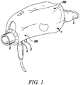
- Figures 1
- is a perspective view showing the exterior of the apparatus from its machine end;
- Figure 2
- is an exploded perspective view of the interior of the apparatus;
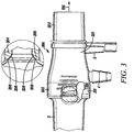
- Figure 3
- is a partly cut-away side elevation view of the inspiratory air inlet and the air entrainment device of the apparatus;
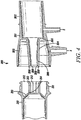
- Figure 4
- is a sectional side elevation view of the air entrainment inlet showing the parts separated;
- Figure 5
- shows schematically operation of the air entrainment inlet; and
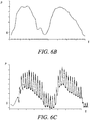
- Figures 6A to 6C
- are graphs showing pressure curves.
- With reference first to
Figure 1 , the apparatus has ahousing 1 with apatient interface 2 at one end in the form of a mouthpiece, although it could include other interfaces such as, for example, a face mask or adaptor for connection to a tracheal tube. At its opposite end thehousing 1 has anair inlet 3 open to atmosphere. Thehousing 1 encloses a series arrangement of an oscillatory O-PEP device 100 and anair entrainment device 200 that provides theair inlet 3. Aside inlet port 4 and apressure monitoring port 5 both open into theair entrainment device 200 as described in greater detail below. - With reference now also to
Figure 2 , the O-PEP device 100 is similar to an "Acapella" respiratory therapy device comprising arocker assembly 101 contained within theouter housing 1 provided by anupper part 103 and a lower part 104 of substantially semi-cylindrical shape. Thedevice 100 is completed by anadjustable dial 105 of circular section. Therocker assembly 101 includes anair flow tube 106 with abreathing inlet 107 at the end of thepatient interface 2 and theinspiratory air inlet 3 at the opposite end including a one-way valve (not shown) that allows air to flow into the air flow tube 6 but prevents air flowing out through the inspiratory inlet. Theair flow tube 106 has an outlet opening 110 with a non-linear profile that is opened and closed by aconical valve element 111 mounted on arocker arm 112 pivoted midway along its length about a transverse axis. Theair flow tube 106 andhousing 1 provide a structure with which therocker arm 112 is mounted. At its far end, remote from thebreathing inlet 107, therocker arm 112 carries aniron pin 113 that interacts with the magnetic field produced by a permanent magnet (not visible) mounted on anadjustable support frame 114. The magnet arrangement is such that, when the patient is not breathing through the device, the far end of therocker arm 112 is held down such that itsvalve element 111 is also held down in sealing engagement with the outlet opening 110. Acam follower projection 115 at one end of thesupport frame 114 locates in acam slot 116 in thedial 105 such that, by rotating the dial, thesupport frame 114, with its magnet, can be moved up or down to alter the strength of the magnetic field interacting with theiron pin 113. Thedial 115 enables the frequency of operation and the resistance to flow of air through the device to be adjusted for maximum therapeutic benefit to the user. Other O-PEP devices may have different setting arrangements for adjusting operation of the device and may be graduated in other ways, such as in frequency. - When the patient inhales through the
mouthpiece 2 air is drawn through theinspiratory inlet 3 and along theair flow tube 106 to thebreathing inlet 107. When the patient exhales, the one-way valve in theinspiratory inlet 3 closes, preventing any air flowing out along this path. Instead, the expiratory pressure is applied to the underside of thevalve element 111 on therocker arm 112 causing it to be lifted up out of theopening 110 against the magnetic attraction, thereby allowing air to flow out to atmosphere. Theopening 110 has a non-linear profile, which causes the effective discharge area to increase as the far end of therocker arm 112 lifts, thereby allowing the arm to fall back down and close the opening. As long as the user keeps applying sufficient expiratory pressure, therocker arm 112 will rise and fall repeatedly as theopening 110 is opened and closed, causing a vibratory, alternating or oscillating interruption to expiratory breath flow through the device. The construction and operation of the device is similar to that described inUS6581598 . - With reference now also to
Figures 3 to 5 , theinspiratory air inlet 3 is provided through the air entrainment arrangement ordevice 200, which, when in operation, acts to amplify the flow of atmospheric air into theair flow tube 106 and hence to the patient's respiratory system. This maintains a positive airway pressure (PAP) delivered to the patient. The one-way valve that prevents the patient exhaling through theair inlet 3 may be positioned rearwardly, to the left of theair entrainment device 200, that is between the air entrainment device and atmosphere, or it may be positioned on the opposite side of the air entrainment device, between this and the O-PEP device 100. Alternatively, the one-way valve may be omitted entirely if theair entrainment device 200 creates sufficient back pressure during use to restrict exhalation through theair inlet 3. - The
entrainment device 200 includes aforward section 201 having acylindrical portion 202 provided by towards its patient end and a frusto-conical portion 203 towards its rear end, the frusto-conical portion being arranged with its narrower end towards the patient. Theinlet port 4 projects radially outwardly of theforward section 201 and has a barbed outer surface onto which an end of resilient gas tubing 118 (Fig 2 ) can be pushed and retained. Theinlet port 4 opens into thecasing 201 towards its wider end. Thepressure monitoring port 5 opens into thecasing 201 on the patient side of theinlet port 4. Aninternal conduit 204 extends coaxially within the frusto-conical portion 203 of thecasing 201 from alateral support wall 205 located at the narrow end of the frusto-conical portion. Theconduit 204 tapers slightly along its length from thewall 205, where it is wider, to its left-hand,free end 206, where it is narrower. The inside of thefree end 206 is shaped with an inwardly-stepped Coandaprofile 208. Theentrainment device 200 also includes arear section 210 having aforward end collar 211 fitted within the rear end of the frusto-conical portion 203. Several fins orvanes 212 are spaced around the inside of therear section 210, the inner ends of the vanes contacting the outside of theconduit 204. An internal, frusto-conical wall 213 extends inwardly and rearwardly around the forward end of thevanes 212. The inner end of thewall 213 defines aring orifice 214 that lies close to thefree end 206 of theconduit 204. The spacing of thefree end 206 of theconduit 204 from theorifice 214 is preferably between about 0.025 mm and 0.127mm, preferably being about 0.05mm, which has been found to produce a Coanda effect when gas is introduced at a rate of between 5 litres per minute and 15 litres per minute. - To produce the Coanda effect the Coanda profile is formed by several inwardly-stepped
portions 208 of thefree end 206 of theconduit 204 with an angular relationship of between about 25° and 35° from the axis of the conduit as shown most clearly inFigure 3 . When pressurised gas is introduced through thegas port 4 at the preferred flow rate the gas will flow into the space between theconduit 204 and the frusto-conical portion 203 and between thevanes 212 towards the gap between thefree end 206 of theconduit 204 and theorifice 214. The gas flows across theCoanda profile 208 creating a high velocity, turbulent flow that effectively entrains ambient air drawn into theair inlet 3 by the inspiratory effort of the patient and directs the flow towards the patient end of theair flow tube 106, as illustrated inFigure 5 . During inhalation, positive air pressure (PAP) is provided to the patient and the flow of ambient air towards the patient is amplified by the Coanda effect. - During exhalation, the expiratory flow generated by the patient overcomes the force of the compressed gas flowing across the Coanda profile so that the Coanda effect ceases. If the one-way valve were positioned between the
entrainment device 200 and the O-PEP device 100 the valve would close during exhalation and thereby isolate the entrainment device. -
Figure 6A illustrates a typical pressure/time curve of a conventional O-PEP vibratory device alone showing that the mean inspiratory pressure is negative and that the vibratory effect only occurs during expiration.Figure 6B illustrates how theair entrainment device 200 would function by itself to provide a mean inspiratory pressure that was positive but without any vibrating or oscillatory therapy effect.Figure 6C shows the combined effect of thevibratory device 100 with theair entrainment device 200 operational. This combination results in a mean inspiratory pressure that is positive and a vibratory effect that is produced both during patient expiratory and inspiratory phases. This could help patients with some sort of atelectasis or secretion clearance problems. - This positive airway pressure (PAP) is generated by the
air entrainment device 200 when gas pressure is supplied to theinlet port 4. Typically, the gas would be air or a gas mixture containing oxygen at higher than atmospheric levels of concentration, such as pure oxygen, and would be supplied at a pressure of around 50 psi (3.4 x 10⁵ pascal). The gas could be supplied by a cylinder of compressed gas 119 (Fig 2 ), a hospital air or oxygen supply or from a domestic nebuliser compressor although the latter may have lower pressures and reduce the effectiveness of the PAP delivered. Where an oxygen-rich gas is used this mixes with the entrained ambient air to produce an oxygen enriched mixture supplied to the patient. - If gas supply to the
air inlet 4 is terminated the positive airway pressure ceases and the apparatus functions as a conventional oscillatory respiratory therapy device. The series arrangement of theair entrainment device 200 and theoscillatory therapy device 100 and the open passage through the air entrainment device enable gas to flow through freely when the air entrainment device is not in operation. Alternatively, it would be possible to lock theoscillatory mechanism 100 closed so that the apparatus functions solely as a positive airway pressure device. - The
pressure monitoring port 5 would normally be capped except when pressure monitoring was needed. Alternatively, theport 5 could be connected to a pressure monitor indicator mounted on the apparatus to give the patient or clinician constant information about the pressure levels. - Apparatus according to the present invention can be used by patients who normally have difficulty using conventional oscillatory expiratory therapy devices such as those patients with relatively low expiratory flow capacity.
Claims (5)
- Respiratory therapy apparatus including a respiratory therapy device (100) having a patient interface (2) and a mechanism (101, 110, 111, 112) arranged to produce an oscillating resistance to expiratory flow through the device, wherein the therapy apparatus additionally includes an arrangement (200) for generating a continuous flow of inspiratory respiratory gas to the patient, that the arrangement (200) includes a gas inlet (4) arranged to receive a supply of respiratory gas at elevated pressure and an air entrainment device (200) arranged to receive gas from the inlet (4) such as to entrain air and deliver a positive airway pressure to the patient interface (2).
- Apparatus according to Claim 1, characterised in that the mechanism arranged to produce an oscillating resistance to expiratory flow includes a valve element (111) on a rocker arm (112) that opens and closes an opening (110) during exhalation through the apparatus.
- Apparatus according to Claim 1 or 2, characterised in that the air entrainment device (200) includes a ring orifice (214) arranged to receive the gas at elevated pressure and to amplify inspiratory gas flow to the patient interface (2) by entraining air through the orifice (214).
- Apparatus according to any one of the preceding claims, characterised in that the gas at elevated pressure has an oxygen concentration at higher than atmospheric concentrations.
- Apparatus according to any one of the preceding claims, characterised in that the apparatus includes an air flow tube (106) opening at one end into the patient interface (2) and opening at its opposite end into the arrangement (200) for generating a continuous flow of inspiratory respiratory gas to the patient, and that the air flow tube (106) opens into the mechanism (101, 110, 111, 112) arranged to produce an oscillating resistance to expiratory flow through the device at a location between the patient interface (2) and the arrangement (200) for generating a continuous flow of inspiratory respiratory gas.
Applications Claiming Priority (2)
| Application Number | Priority Date | Filing Date | Title |
|---|---|---|---|
| GBGB1420127.1A GB201420127D0 (en) | 2014-11-12 | 2014-11-12 | Respiratory therapy apparatus |
| PCT/GB2015/000278 WO2016075426A1 (en) | 2014-11-12 | 2015-09-30 | Respiratory therapy apparatus |
Publications (2)
| Publication Number | Publication Date |
|---|---|
| EP3218040A1 EP3218040A1 (en) | 2017-09-20 |
| EP3218040B1 true EP3218040B1 (en) | 2019-10-30 |
Family
ID=52118382
Family Applications (1)
| Application Number | Title | Priority Date | Filing Date |
|---|---|---|---|
| EP15818015.8A Active EP3218040B1 (en) | 2014-11-12 | 2015-09-30 | Respiratory therapy apparatus |
Country Status (7)
| Country | Link |
|---|---|
| US (1) | US11154674B2 (en) |
| EP (1) | EP3218040B1 (en) |
| AU (1) | AU2015344933A1 (en) |
| CA (1) | CA2965587C (en) |
| ES (1) | ES2770081T3 (en) |
| GB (1) | GB201420127D0 (en) |
| WO (1) | WO2016075426A1 (en) |
Families Citing this family (20)
| Publication number | Priority date | Publication date | Assignee | Title |
|---|---|---|---|---|
| US20170055574A1 (en) | 2015-08-31 | 2017-03-02 | British American Tobacco (Investments) Limited | Cartridge for use with apparatus for heating smokable material |
| US20170119051A1 (en) | 2015-10-30 | 2017-05-04 | British American Tobacco (Investments) Limited | Article for Use with Apparatus for Heating Smokable Material |
| US20180317554A1 (en) | 2015-10-30 | 2018-11-08 | British American Tobacco (Investments) Limited | Article for use with apparatus for heating smokable material |
| US20170119049A1 (en) | 2015-10-30 | 2017-05-04 | British American Tobacco (Investments) Limited | Article for Use with Apparatus for Heating Smokable Material |
| US20170119050A1 (en) | 2015-10-30 | 2017-05-04 | British American Tobacco (Investments) Limited | Article for Use with Apparatus for Heating Smokable Material |
| KR102468749B1 (en) | 2016-06-29 | 2022-11-17 | 니코벤처스 트레이딩 리미티드 | Apparatus for heating smokable material |
| EP3478104B1 (en) | 2016-06-29 | 2023-03-22 | Nicoventures Trading Limited | Apparatus for heating smokable material |
| US12478096B2 (en) | 2016-06-29 | 2025-11-25 | Nicoventures Trading Limited | Apparatus for heating smokable material |
| CA3075657C (en) | 2017-09-15 | 2023-10-10 | British American Tobacco (Investments) Limited | Apparatus for heating smokable material |
| ES2955038T3 (en) | 2018-06-04 | 2023-11-28 | Trudell Medical Int | Positive air pressure therapy device |
| GB201809559D0 (en) * | 2018-06-09 | 2018-07-25 | Smiths Medical International Ltd | Respiratory therapy apparatus and methods |
| US11400250B2 (en) | 2018-12-05 | 2022-08-02 | Aires Medical LLC | Mechanical ventilator with non-invasive option |
| US11229763B2 (en) * | 2018-12-05 | 2022-01-25 | Aires Medical LLC | Mechanical ventilator with oxygen concentrator |
| US12589213B2 (en) | 2018-12-05 | 2026-03-31 | Goldman Sephoric Llc | Mechanical ventilator with non-invasive option |
| US11135392B2 (en) | 2018-12-05 | 2021-10-05 | Aires Medical LLC | Mechanical ventilator |
| US11123505B2 (en) | 2018-12-05 | 2021-09-21 | Aires Medical LLC | Breathing apparatus with breath detection software |
| GB201904825D0 (en) | 2019-04-05 | 2019-05-22 | Smiths Medical International Ltd | Respiratory therapy apparatus |
| WO2022040257A1 (en) * | 2020-08-18 | 2022-02-24 | Aires Medical LLC | Mechanical ventilator |
| USD1035880S1 (en) * | 2021-05-28 | 2024-07-16 | Evolved, Llc | Respiratory trainer |
| CN113648619A (en) * | 2021-09-26 | 2021-11-16 | 重庆上品益生电子商务有限公司 | breathing trainer |
Family Cites Families (9)
| Publication number | Priority date | Publication date | Assignee | Title |
|---|---|---|---|---|
| US6253766B1 (en) | 1999-08-24 | 2001-07-03 | Dhd Healthcare Corporation | Continuous positive airway pressure therapy device |
| US7059324B2 (en) * | 1999-11-24 | 2006-06-13 | Smiths Medical Asd, Inc. | Positive expiratory pressure device with bypass |
| US6776159B2 (en) | 1999-11-24 | 2004-08-17 | Dhd Healthcare Corporation | Positive expiratory pressure device with bypass |
| US6581598B1 (en) | 1999-11-24 | 2003-06-24 | Dhd Healthcare Corporation | Positive expiratory pressure device |
| EP1772165A1 (en) | 2005-10-08 | 2007-04-11 | Ulrich Cegla | Inhalation apparatus |
| US8225785B2 (en) * | 2006-10-03 | 2012-07-24 | Smiths Medical Asd, Inc. | Vibratory PEP therapy system with medicated aerosol nebulizer |
| US7779841B2 (en) | 2006-11-13 | 2010-08-24 | Carefusion 2200, Inc. | Respiratory therapy device and method |
| US9180271B2 (en) | 2012-03-05 | 2015-11-10 | Hill-Rom Services Pte. Ltd. | Respiratory therapy device having standard and oscillatory PEP with nebulizer |
| ES2955038T3 (en) * | 2018-06-04 | 2023-11-28 | Trudell Medical Int | Positive air pressure therapy device |
-
2014
- 2014-11-12 GB GBGB1420127.1A patent/GB201420127D0/en not_active Ceased
-
2015
- 2015-09-30 AU AU2015344933A patent/AU2015344933A1/en not_active Abandoned
- 2015-09-30 EP EP15818015.8A patent/EP3218040B1/en active Active
- 2015-09-30 US US15/522,873 patent/US11154674B2/en active Active
- 2015-09-30 ES ES15818015T patent/ES2770081T3/en active Active
- 2015-09-30 CA CA2965587A patent/CA2965587C/en active Active
- 2015-09-30 WO PCT/GB2015/000278 patent/WO2016075426A1/en not_active Ceased
Non-Patent Citations (1)
| Title |
|---|
| None * |
Also Published As
| Publication number | Publication date |
|---|---|
| WO2016075426A1 (en) | 2016-05-19 |
| AU2015344933A1 (en) | 2017-04-27 |
| CA2965587C (en) | 2023-02-14 |
| CA2965587A1 (en) | 2016-05-19 |
| ES2770081T3 (en) | 2020-06-30 |
| GB201420127D0 (en) | 2014-12-24 |
| EP3218040A1 (en) | 2017-09-20 |
| US20170319800A1 (en) | 2017-11-09 |
| US11154674B2 (en) | 2021-10-26 |
Similar Documents
| Publication | Publication Date | Title |
|---|---|---|
| CA2965587C (en) | Respiratory therapy apparatus | |
| EP3169412B1 (en) | Respiratory therapy assemblies | |
| EP2134397B1 (en) | High frequency oscillation respiratory therapy device | |
| JP4411165B2 (en) | Continuous high frequency vibration respiratory treatment device | |
| US6253766B1 (en) | Continuous positive airway pressure therapy device | |
| EP1908489B1 (en) | Vibratory pep therapy system with medicated aerosol nebulizer | |
| EP1103287A2 (en) | Positive expiratory pressure device | |
| JP2004209252A (en) | Oscillatory positive expiratory pressure respiratory therapy device, and method for selectively conducting oscillatory positive expiratory pressure respiratory therapy | |
| JP6961904B2 (en) | Breathing monitoring device | |
| US20210252236A1 (en) | Respiratory therapy devices and assemblies | |
| US20220080146A1 (en) | Respiratory Auxiliary Apparatus | |
| JP3860327B2 (en) | Ventilator | |
| ITBS20130072A1 (en) | EQUIPMENT FOR RESPIRATORY REHABILITATION PHYSIOTHERAPY | |
| CN116635100A (en) | Fluid mixing equipment such as respirators | |
| TWI763508B (en) | Fluid mixing apparatus such as a ventilator | |
| CN119746226A (en) | Portable vibration sputum excretion instrument and control method | |
| US20240269423A1 (en) | Respiratory therapy devices | |
| EP4366808B1 (en) | Respiratory therapy devices | |
| JP3860330B2 (en) | Ventilator | |
| JP3860328B2 (en) | Ventilator | |
| ITBS20120105A1 (en) | EQUIPMENT FOR RESPIRATORY PHYSIOTHERAPY |
Legal Events
| Date | Code | Title | Description |
|---|---|---|---|
| STAA | Information on the status of an ep patent application or granted ep patent |
Free format text: STATUS: THE INTERNATIONAL PUBLICATION HAS BEEN MADE |
|
| PUAI | Public reference made under article 153(3) epc to a published international application that has entered the european phase |
Free format text: ORIGINAL CODE: 0009012 |
|
| STAA | Information on the status of an ep patent application or granted ep patent |
Free format text: STATUS: REQUEST FOR EXAMINATION WAS MADE |
|
| 17P | Request for examination filed |
Effective date: 20170612 |
|
| AK | Designated contracting states |
Kind code of ref document: A1 Designated state(s): AL AT BE BG CH CY CZ DE DK EE ES FI FR GB GR HR HU IE IS IT LI LT LU LV MC MK MT NL NO PL PT RO RS SE SI SK SM TR |
|
| AX | Request for extension of the european patent |
Extension state: BA ME |
|
| DAV | Request for validation of the european patent (deleted) | ||
| DAX | Request for extension of the european patent (deleted) | ||
| GRAP | Despatch of communication of intention to grant a patent |
Free format text: ORIGINAL CODE: EPIDOSNIGR1 |
|
| STAA | Information on the status of an ep patent application or granted ep patent |
Free format text: STATUS: GRANT OF PATENT IS INTENDED |
|
| INTG | Intention to grant announced |
Effective date: 20190627 |
|
| GRAS | Grant fee paid |
Free format text: ORIGINAL CODE: EPIDOSNIGR3 |
|
| GRAA | (expected) grant |
Free format text: ORIGINAL CODE: 0009210 |
|
| STAA | Information on the status of an ep patent application or granted ep patent |
Free format text: STATUS: THE PATENT HAS BEEN GRANTED |
|
| AK | Designated contracting states |
Kind code of ref document: B1 Designated state(s): AL AT BE BG CH CY CZ DE DK EE ES FI FR GB GR HR HU IE IS IT LI LT LU LV MC MK MT NL NO PL PT RO RS SE SI SK SM TR |
|
| REG | Reference to a national code |
Ref country code: GB Ref legal event code: FG4D |
|
| REG | Reference to a national code |
Ref country code: CH Ref legal event code: EP |
|
| REG | Reference to a national code |
Ref country code: AT Ref legal event code: REF Ref document number: 1195487 Country of ref document: AT Kind code of ref document: T Effective date: 20191115 |
|
| REG | Reference to a national code |
Ref country code: DE Ref legal event code: R096 Ref document number: 602015040809 Country of ref document: DE |
|
| REG | Reference to a national code |
Ref country code: IE Ref legal event code: FG4D |
|
| REG | Reference to a national code |
Ref country code: LT Ref legal event code: MG4D |
|
| PG25 | Lapsed in a contracting state [announced via postgrant information from national office to epo] |
Ref country code: BG Free format text: LAPSE BECAUSE OF FAILURE TO SUBMIT A TRANSLATION OF THE DESCRIPTION OR TO PAY THE FEE WITHIN THE PRESCRIBED TIME-LIMIT Effective date: 20200130 Ref country code: PT Free format text: LAPSE BECAUSE OF FAILURE TO SUBMIT A TRANSLATION OF THE DESCRIPTION OR TO PAY THE FEE WITHIN THE PRESCRIBED TIME-LIMIT Effective date: 20200302 Ref country code: LV Free format text: LAPSE BECAUSE OF FAILURE TO SUBMIT A TRANSLATION OF THE DESCRIPTION OR TO PAY THE FEE WITHIN THE PRESCRIBED TIME-LIMIT Effective date: 20191030 Ref country code: SE Free format text: LAPSE BECAUSE OF FAILURE TO SUBMIT A TRANSLATION OF THE DESCRIPTION OR TO PAY THE FEE WITHIN THE PRESCRIBED TIME-LIMIT Effective date: 20191030 Ref country code: NL Free format text: LAPSE BECAUSE OF FAILURE TO SUBMIT A TRANSLATION OF THE DESCRIPTION OR TO PAY THE FEE WITHIN THE PRESCRIBED TIME-LIMIT Effective date: 20191030 Ref country code: LT Free format text: LAPSE BECAUSE OF FAILURE TO SUBMIT A TRANSLATION OF THE DESCRIPTION OR TO PAY THE FEE WITHIN THE PRESCRIBED TIME-LIMIT Effective date: 20191030 Ref country code: PL Free format text: LAPSE BECAUSE OF FAILURE TO SUBMIT A TRANSLATION OF THE DESCRIPTION OR TO PAY THE FEE WITHIN THE PRESCRIBED TIME-LIMIT Effective date: 20191030 Ref country code: GR Free format text: LAPSE BECAUSE OF FAILURE TO SUBMIT A TRANSLATION OF THE DESCRIPTION OR TO PAY THE FEE WITHIN THE PRESCRIBED TIME-LIMIT Effective date: 20200131 Ref country code: NO Free format text: LAPSE BECAUSE OF FAILURE TO SUBMIT A TRANSLATION OF THE DESCRIPTION OR TO PAY THE FEE WITHIN THE PRESCRIBED TIME-LIMIT Effective date: 20200130 |
|
| REG | Reference to a national code |
Ref country code: NL Ref legal event code: MP Effective date: 20191030 |
|
| PG25 | Lapsed in a contracting state [announced via postgrant information from national office to epo] |
Ref country code: IS Free format text: LAPSE BECAUSE OF FAILURE TO SUBMIT A TRANSLATION OF THE DESCRIPTION OR TO PAY THE FEE WITHIN THE PRESCRIBED TIME-LIMIT Effective date: 20200229 Ref country code: RS Free format text: LAPSE BECAUSE OF FAILURE TO SUBMIT A TRANSLATION OF THE DESCRIPTION OR TO PAY THE FEE WITHIN THE PRESCRIBED TIME-LIMIT Effective date: 20191030 Ref country code: HR Free format text: LAPSE BECAUSE OF FAILURE TO SUBMIT A TRANSLATION OF THE DESCRIPTION OR TO PAY THE FEE WITHIN THE PRESCRIBED TIME-LIMIT Effective date: 20191030 |
|
| PG25 | Lapsed in a contracting state [announced via postgrant information from national office to epo] |
Ref country code: AL Free format text: LAPSE BECAUSE OF FAILURE TO SUBMIT A TRANSLATION OF THE DESCRIPTION OR TO PAY THE FEE WITHIN THE PRESCRIBED TIME-LIMIT Effective date: 20191030 |
|
| REG | Reference to a national code |
Ref country code: ES Ref legal event code: FG2A Ref document number: 2770081 Country of ref document: ES Kind code of ref document: T3 Effective date: 20200630 |
|
| PG25 | Lapsed in a contracting state [announced via postgrant information from national office to epo] |
Ref country code: RO Free format text: LAPSE BECAUSE OF FAILURE TO SUBMIT A TRANSLATION OF THE DESCRIPTION OR TO PAY THE FEE WITHIN THE PRESCRIBED TIME-LIMIT Effective date: 20191030 Ref country code: CZ Free format text: LAPSE BECAUSE OF FAILURE TO SUBMIT A TRANSLATION OF THE DESCRIPTION OR TO PAY THE FEE WITHIN THE PRESCRIBED TIME-LIMIT Effective date: 20191030 Ref country code: EE Free format text: LAPSE BECAUSE OF FAILURE TO SUBMIT A TRANSLATION OF THE DESCRIPTION OR TO PAY THE FEE WITHIN THE PRESCRIBED TIME-LIMIT Effective date: 20191030 Ref country code: DK Free format text: LAPSE BECAUSE OF FAILURE TO SUBMIT A TRANSLATION OF THE DESCRIPTION OR TO PAY THE FEE WITHIN THE PRESCRIBED TIME-LIMIT Effective date: 20191030 |
|
| REG | Reference to a national code |
Ref country code: DE Ref legal event code: R097 Ref document number: 602015040809 Country of ref document: DE |
|
| PG25 | Lapsed in a contracting state [announced via postgrant information from national office to epo] |
Ref country code: SK Free format text: LAPSE BECAUSE OF FAILURE TO SUBMIT A TRANSLATION OF THE DESCRIPTION OR TO PAY THE FEE WITHIN THE PRESCRIBED TIME-LIMIT Effective date: 20191030 Ref country code: SM Free format text: LAPSE BECAUSE OF FAILURE TO SUBMIT A TRANSLATION OF THE DESCRIPTION OR TO PAY THE FEE WITHIN THE PRESCRIBED TIME-LIMIT Effective date: 20191030 Ref country code: IT Free format text: LAPSE BECAUSE OF FAILURE TO SUBMIT A TRANSLATION OF THE DESCRIPTION OR TO PAY THE FEE WITHIN THE PRESCRIBED TIME-LIMIT Effective date: 20191030 |
|
| PLBE | No opposition filed within time limit |
Free format text: ORIGINAL CODE: 0009261 |
|
| STAA | Information on the status of an ep patent application or granted ep patent |
Free format text: STATUS: NO OPPOSITION FILED WITHIN TIME LIMIT |
|
| 26N | No opposition filed |
Effective date: 20200731 |
|
| PG25 | Lapsed in a contracting state [announced via postgrant information from national office to epo] |
Ref country code: SI Free format text: LAPSE BECAUSE OF FAILURE TO SUBMIT A TRANSLATION OF THE DESCRIPTION OR TO PAY THE FEE WITHIN THE PRESCRIBED TIME-LIMIT Effective date: 20191030 |
|
| REG | Reference to a national code |
Ref country code: CH Ref legal event code: PL |
|
| REG | Reference to a national code |
Ref country code: BE Ref legal event code: MM Effective date: 20200930 |
|
| PG25 | Lapsed in a contracting state [announced via postgrant information from national office to epo] |
Ref country code: LU Free format text: LAPSE BECAUSE OF NON-PAYMENT OF DUE FEES Effective date: 20200930 |
|
| PG25 | Lapsed in a contracting state [announced via postgrant information from national office to epo] |
Ref country code: FR Free format text: LAPSE BECAUSE OF NON-PAYMENT OF DUE FEES Effective date: 20200930 |
|
| PG25 | Lapsed in a contracting state [announced via postgrant information from national office to epo] |
Ref country code: LI Free format text: LAPSE BECAUSE OF NON-PAYMENT OF DUE FEES Effective date: 20200930 Ref country code: IE Free format text: LAPSE BECAUSE OF NON-PAYMENT OF DUE FEES Effective date: 20200930 Ref country code: CH Free format text: LAPSE BECAUSE OF NON-PAYMENT OF DUE FEES Effective date: 20200930 Ref country code: BE Free format text: LAPSE BECAUSE OF NON-PAYMENT OF DUE FEES Effective date: 20200930 |
|
| REG | Reference to a national code |
Ref country code: AT Ref legal event code: UEP Ref document number: 1195487 Country of ref document: AT Kind code of ref document: T Effective date: 20191030 |
|
| PG25 | Lapsed in a contracting state [announced via postgrant information from national office to epo] |
Ref country code: TR Free format text: LAPSE BECAUSE OF FAILURE TO SUBMIT A TRANSLATION OF THE DESCRIPTION OR TO PAY THE FEE WITHIN THE PRESCRIBED TIME-LIMIT Effective date: 20191030 Ref country code: MT Free format text: LAPSE BECAUSE OF FAILURE TO SUBMIT A TRANSLATION OF THE DESCRIPTION OR TO PAY THE FEE WITHIN THE PRESCRIBED TIME-LIMIT Effective date: 20191030 Ref country code: CY Free format text: LAPSE BECAUSE OF FAILURE TO SUBMIT A TRANSLATION OF THE DESCRIPTION OR TO PAY THE FEE WITHIN THE PRESCRIBED TIME-LIMIT Effective date: 20191030 |
|
| PG25 | Lapsed in a contracting state [announced via postgrant information from national office to epo] |
Ref country code: MK Free format text: LAPSE BECAUSE OF FAILURE TO SUBMIT A TRANSLATION OF THE DESCRIPTION OR TO PAY THE FEE WITHIN THE PRESCRIBED TIME-LIMIT Effective date: 20191030 Ref country code: MC Free format text: LAPSE BECAUSE OF FAILURE TO SUBMIT A TRANSLATION OF THE DESCRIPTION OR TO PAY THE FEE WITHIN THE PRESCRIBED TIME-LIMIT Effective date: 20191030 |
|
| P01 | Opt-out of the competence of the unified patent court (upc) registered |
Effective date: 20230419 |
|
| REG | Reference to a national code |
Ref country code: DE Ref legal event code: R081 Ref document number: 602015040809 Country of ref document: DE Owner name: ICU MEDICAL INTERNATIONAL LTD., ASHFORD, GB Free format text: FORMER OWNER: SMITHS MEDICAL INTERNATIONAL LTD., ASHFORD, KENT, GB |
|
| REG | Reference to a national code |
Ref country code: ES Ref legal event code: PC2A Owner name: ICU MEDICAL INTERNATIONAL LIMITED Effective date: 20250702 |
|
| PGFP | Annual fee paid to national office [announced via postgrant information from national office to epo] |
Ref country code: FI Payment date: 20250912 Year of fee payment: 11 |
|
| PGFP | Annual fee paid to national office [announced via postgrant information from national office to epo] |
Ref country code: DE Payment date: 20250805 Year of fee payment: 11 |
|
| PGFP | Annual fee paid to national office [announced via postgrant information from national office to epo] |
Ref country code: GB Payment date: 20250807 Year of fee payment: 11 |
|
| PGFP | Annual fee paid to national office [announced via postgrant information from national office to epo] |
Ref country code: AT Payment date: 20250827 Year of fee payment: 11 |
|
| PGFP | Annual fee paid to national office [announced via postgrant information from national office to epo] |
Ref country code: ES Payment date: 20251017 Year of fee payment: 11 |