EP3217603A1 - Communications device having relay - Google Patents
Communications device having relay Download PDFInfo
- Publication number
- EP3217603A1 EP3217603A1 EP16195453.2A EP16195453A EP3217603A1 EP 3217603 A1 EP3217603 A1 EP 3217603A1 EP 16195453 A EP16195453 A EP 16195453A EP 3217603 A1 EP3217603 A1 EP 3217603A1
- Authority
- EP
- European Patent Office
- Prior art keywords
- relay
- port
- communications
- unit
- slave
- Prior art date
- Legal status (The legal status is an assumption and is not a legal conclusion. Google has not performed a legal analysis and makes no representation as to the accuracy of the status listed.)
- Granted
Links
- 238000012546 transfer Methods 0.000 claims description 2
- 238000010586 diagram Methods 0.000 description 7
- 230000005856 abnormality Effects 0.000 description 6
- 238000000034 method Methods 0.000 description 5
- 230000002159 abnormal effect Effects 0.000 description 1
- 238000013459 approach Methods 0.000 description 1
- 238000013461 design Methods 0.000 description 1
- 238000005516 engineering process Methods 0.000 description 1
- 238000009434 installation Methods 0.000 description 1
- 238000012423 maintenance Methods 0.000 description 1
Images



Classifications
-
- H—ELECTRICITY
- H04—ELECTRIC COMMUNICATION TECHNIQUE
- H04L—TRANSMISSION OF DIGITAL INFORMATION, e.g. TELEGRAPHIC COMMUNICATION
- H04L12/00—Data switching networks
- H04L12/28—Data switching networks characterised by path configuration, e.g. LAN [Local Area Networks] or WAN [Wide Area Networks]
- H04L12/40—Bus networks
- H04L12/40169—Flexible bus arrangements
- H04L12/40176—Flexible bus arrangements involving redundancy
-
- H—ELECTRICITY
- H04—ELECTRIC COMMUNICATION TECHNIQUE
- H04L—TRANSMISSION OF DIGITAL INFORMATION, e.g. TELEGRAPHIC COMMUNICATION
- H04L12/00—Data switching networks
- H04L12/02—Details
- H04L12/10—Current supply arrangements
-
- H—ELECTRICITY
- H04—ELECTRIC COMMUNICATION TECHNIQUE
- H04L—TRANSMISSION OF DIGITAL INFORMATION, e.g. TELEGRAPHIC COMMUNICATION
- H04L12/00—Data switching networks
- H04L12/28—Data switching networks characterised by path configuration, e.g. LAN [Local Area Networks] or WAN [Wide Area Networks]
- H04L12/40—Bus networks
- H04L12/40169—Flexible bus arrangements
-
- H—ELECTRICITY
- H04—ELECTRIC COMMUNICATION TECHNIQUE
- H04L—TRANSMISSION OF DIGITAL INFORMATION, e.g. TELEGRAPHIC COMMUNICATION
- H04L12/00—Data switching networks
- H04L12/02—Details
- H04L12/12—Arrangements for remote connection or disconnection of substations or of equipment thereof
-
- H—ELECTRICITY
- H04—ELECTRIC COMMUNICATION TECHNIQUE
- H04L—TRANSMISSION OF DIGITAL INFORMATION, e.g. TELEGRAPHIC COMMUNICATION
- H04L13/00—Details of the apparatus or circuits covered by groups H04L15/00 or H04L17/00
- H04L13/02—Details not particular to receiver or transmitter
- H04L13/10—Distributors
- H04L13/12—Non-mechanical distributors, e.g. relay distributors
-
- H—ELECTRICITY
- H04—ELECTRIC COMMUNICATION TECHNIQUE
- H04L—TRANSMISSION OF DIGITAL INFORMATION, e.g. TELEGRAPHIC COMMUNICATION
- H04L41/00—Arrangements for maintenance, administration or management of data switching networks, e.g. of packet switching networks
- H04L41/06—Management of faults, events, alarms or notifications
- H04L41/0654—Management of faults, events, alarms or notifications using network fault recovery
- H04L41/0668—Management of faults, events, alarms or notifications using network fault recovery by dynamic selection of recovery network elements, e.g. replacement by the most appropriate element after failure
Definitions
- the present disclosure relates to a communications device having relays and more specifically, to a communications device having relays that allow the communications device to conduct communications via the relays even if a power failure occurs.
- Ethernet may be connected in a ring, a line, etc.
- the ring connection is advantageous in that it has simple connection and saves cost, and thus is frequently used.
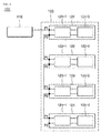
- FIG. 1 is a block diagram of an existing daisy chain communications device.
- the communications device includes a master unit 10, first to fourth slave units 20, 30, 40 and 50.
- the slave units are connected to one another so that they can communicate via first and second ports P1 and P2 of each of the slave units.
- the slave units include communications processors 22, 32, 42 and 52, respectively, to process commands or data received from the master unit 10.
- the first to fourth slave units 20, 30, 40 and 50 may be controlled by the single master unit 10 by using minimal lines to communicate with one another.
- Each of the slave units may include a power module therein to receive power. For example, an inverter may be included.
- the slave unit and the subsequent slave units cannot conduct communications any more.
- the second slave unit 30 cannot conduct communications.
- the third slave unit 40 and the fourth slave unit 50 cannot communicate with others, either after the failure has occurred in the second slave unit 30.
- duplex power a cable that supplies power directly to a slave unit, i.e., duplex power to the communications device.
- This approach may increase installation cost and time, and unexpected difficulty may take place due to many power cables. In addition, a lot of effort may be required for maintenance.
- a communications device includes a master unit and a block of slave units including a plurality of slave units control by the master unit.
- Each of the slave units include first and second ports to which different communications lines are connected, respectively, and a relay disposed between the first port and the second port and open/closed depending on whether power is supplied.
- the relay may be open to make an open circuit between the first port and the second port when the power is supplied.
- the relay may be closed to make a closed circuit between the first port and the second port when the power is not supplied.
- a communications path can be formed that passes the first port and the second port via the relay.
- the slave units may be connected to one another so that they can communicate with one another via the first port and the second port, and if one of the slave units is not powered, the slave unit is able to transfer a command and data to a next slave unit via the relay.
- relays can be selectively connected to conduct communications for emergency when power failure occurs in the communications device.
- other slave units can conduct communications even when power failure occurs in one of the slave units.
- a slave unit with a power failure can perform self bypass function without any additional controller or control signal.
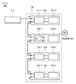
- FIG. 3 is a block diagram of a communications device including relays according to an exemplary embodiment of the present disclosure.
- the communications device 100 includes a master unit 110 and a block 120 of slave units controlled by the master unit 110.
- the block 120 of the slave units includes first to fourth slave units 121, 122, 123 and 124. Although four (4) slave units are illustrated in this exemplary embodiment, the number of the slave units is not limited to four.
- the master unit 110 is connected to the first slave unit 121 so that it can control the slave units 121, 122, 123 and 124 individually.
- the master unit 110 may provide commands and data designated to each of the slave units via the first slave unit 121.
- the master unit 110 may provide the commands and data designated to each of the slave units in the form of packets.
- the first to fourth slave units 121 to 124 connected in a daisy chain may receive and process commands and data designated thereto.
- the first slave unit 121 includes two communications ports, i.e., first and second ports P1 and P2, a first relay unit 121-1 and a first communications processor 121-2.
- each of the slave units may include a power module therein to receive power.
- an inverter may be included.
- the first slave unit 121 is connected to the master unit 110 via the first port P1 and is connected to the second slave unit 122 via the second port P2.
- the first relay unit 121-1 is controlled so that it can conduct communications with the first communications processor 121-2 when power is supplied. In addition, the first relay unit 121-1 is controlled so that it interrupts communications with the first communications processor 121-2 and can conduct communications with the next slave unit, e.g., the second slave unit 122 when power is not supplied.
- the first relay unit 121-1 will be described in more detail below with reference to FIGS. 4 and 5 .
- the first communications processor 121-2 may process commands or data received from the master unit 110.
- the second slave unit 122 has a similar configuration with that of the first slave unit 121.
- the second slave unit 122 includes two communications ports, i.e., first and second ports P1 and P2, a second relay unit 122-1 and a second communications processor 122-2.
- the second slave unit 122 is connected to the first slave unit 121 via the first port P1 and is connected to the third slave unit 123 via the second port P2.
- the functionality and operation of the second relay unit 122-1 and the second communications processor 122-2 included in the second slave unit 122 are identical to those of the first slave unit 121 described above.
- the second relay unit 122-1 is controlled so that it can conduct communications with the second communications processor 122-2.
- the second communications processor 122-2 may process commands or data received from the master unit 110 when the second relay unit 122-1 can conduct communications with it.
- the second relay unit 122-1 is controlled so that it interrupts communications with the second communications processor 122-2 and can conduct communications with the next, third slave unit 123.
- the configuration and operation of the third and fourth slave units 123 and 124 are identical to those of the first and second slave units 121 and 122; and, therefore, redundant description will be omitted.
- one of the slave units can conduct communications
- its communications processor 121-2, 122-3, 123-2 or 124-2 can receive and process commands or data sent from the master unit 110.
- first and second ports P1 and P2 included in each of the slave units 121, 122, 123 and 124 are indicated by the same reference numerals for convenience of illustration, it is to be noted that they are difference ports at different physical locations.
- the first and second ports P1 and P2 may be RJ45 ports.
- each of the ports shown in FIG. 3 has a single line, each of the ports may include a plurality of lines, e.g., eight lines. However, the number of the lines is not limited herein. In other words, the configuration of the ports and the connection of the lines are not particularly limited herein.
- the configuration of the ports and the connection of the lines are not particularly limited herein as long as they can maintain communications via one of the relay units 121-1, 122-1, 123-1 and 124-1 even when one of the slave units is not powered.
- the first relay unit 121-1 will be described in detail with reference to FIGS. 4 and 5 .
- the configuration of the relay units 122-1, 123-1 and 124-1 in the slave units 122-1, 123-1 and 124-1, respectively, is similar to that of the first relay 121-1, and thus the rest of the relay units 122-1, 123-1 and 124-1 will not be described to avoid redundancy.
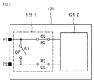
- FIG. 4 shows connection of the first relay 121-1 of the first slave unit 121 in the normal operation.
- the first relay unit 121-1 includes a first relay R1, a second relay R2 and a third relay R3.
- the first relay R1 is disposed between first and second ports P1 and P2.
- the first relay R1 may be implemented as an a-contact (aille contact) relay.
- the a-contact relay is normally opened (OP) and is closed (CL) by magnetic force in the case of abnormality.
- the contacts are closed to make a closed circuit between the first port P1 and the second port P2.
- the second relay R2 is disposed between the first port P1 and the first communications processor 121-2.
- the second relay R2 may be implemented as a b-contact (break contact) relay. Contrary to the a-contact relay, the b-contact relay is normally closed (CL) and is opened (OP) by magnetic force in the case of abnormality.
- the contacts remain closed.
- the information received via the first port P1 can be processed by the first communications processor 121-2.
- the third relay R3 is disposed between the second port P2 and the first communications processor 121-2.
- the third relay R3 may be implemented as a b-contact (break contact) relay. Specifically, the b-contact relay is normally closed (CL) and is opened (OP) by magnetic force in the case of abnormality.
- the third relay R3 when the third relay R3 is powered, the contacts remain closed. As a result, in the normal operation, the communications with the second slave unit 122 (see FIG. 3 ) can be made via the third relay R3 and the second port P2.
- FIG. 5 shows connection of the first relay unit 121-1 of the first slave unit 121 in the abnormal operation, i.e., when a power failure has occurred.
- the first relay R1 When the first relay R1 is not powered, the first relay R1 is closed (CL) and the second and third relays R2 and R3 are opened (OP).
- the first relay R1 is connected such that a direct communications path from the first port P1 to the second port P2 can be created.
- the communications path is still provided even after the power failure has occurred in the slave unit, and thus commands and data from the master unit 110 (see FIG. 3 ) can be transferred.
- the second and third relays R2 and R3 are opened (OP), such that the first communications processor 121-2 is bypassed.
- the a-contact relay composed of a circuit including an electromagnet and is normally opened (OP), and the contacts are closed by magnetic force in the case of abnormality.
- the b-contact relay also composed of a circuit including an electromagnet. However, unlike the a-contact relay, it is normally closed (CL) and is opened (OP) by magnetic force in the case of abnormality, in this exemplary embodiment, when no power is supplied.
- the second and third relays R2 and R3 are opened. As a result, the communications path can be blocked reliably.
- the communications device employs the a-contact relays and the b-contact relays and control so that communications among other slave units are not affected by a slave unit in which a failure has occurred.
- first relay unit 121-1 is disposed outside the first communications processor 121-2 in this exemplary embodiment, this is merely illustrative.
- the first relay unit 121-1 may be incorporated in an application specific integrated circuit (ASIC) chip inside the first communications processor 121-2 depending on design choice.
- ASIC application specific integrated circuit
- FIG. 6 shows the communications device of FIG. 3 when a failure has occurred.
- Communications are conducted between the master unit 110 and the first slave unit 121.
- the first relay unit 121-1 Since power is supplied to the first slave unit 121, the first relay unit 121-1 provides a path to allow the first communications processor 121-2 to operate. In addition, a communications path for the second slave unit 122 to receive commands and data from the master unit 110 is provided. The connection of the first relay unit 121-1 in the normal operation may be the same as shown in FIG. 4 .
- the first relay R1 of the second relay unit 122-1 in the second slave unit 122 is closed (CL) while the second and third relays R2 and R3 thereof are opened (OP).
- the second communications processor 122-2 in the second slave unit 122 is bypassed, and a communications path can be created in the second slave unit 122 via the first relay R1. Accordingly, even if the second slave unit 122 is not operated due to the power failure, the communications path to the third slave unit 123 can be provided via the first relay R1.
- the third slave unit 123 and the fourth slave unit 124 are powered and operated normally.
- the connection of each of the third and fourth relay units 123-1 and 124-1 may be the same as that shown in FIG. 4 .
- the failure is addressed, i.e., the second slave unit 122 is normally powered, the first relay R1 is opened (OP) while the second and third relays R2 and R3 are closed (CL) automatically.
- the first relay of each of the second relay unit 122-1 and the third relay unit 123-1 is closed.
- the second and third relays of each of the second relay unit 122-1 and the third relay unit 123-1 are opened. Accordingly, the second and third communications processors 122-2 and 123-2 are bypassed, and a communications path can be created via the first relay R1 in each of the second and third slave units 122 and 123. Accordingly, even if the second and third slave units 122 123 are not operated due to the power failure, the communications path to the fourth slave unit 124 can be provided via the first relays.
- relays that are selectively opened and closed depending on whether power is supplied when a power failure occurs in the communications device, there is no need for an additional power line.
- slave units can conduct communications even when a power failure occurs in one of the slave units.
- the slave unit in which the power failure has occurred can be bypassed without an additional controller or a control signal for controlling such operation.
Landscapes
- Engineering & Computer Science (AREA)
- Computer Networks & Wireless Communication (AREA)
- Signal Processing (AREA)
- Small-Scale Networks (AREA)
Abstract
Description
- The present disclosure relates to a communications device having relays and more specifically, to a communications device having relays that allow the communications device to conduct communications via the relays even if a power failure occurs.
- As industrial Ethernet technology is less costly, has high efficiency and is convenient to maintain, more and more applications can be found in the industrial fields in place of field buses. Such Ethernet may be connected in a ring, a line, etc. The ring connection is advantageous in that it has simple connection and saves cost, and thus is frequently used.
-
FIG. 1 is a block diagram of an existing daisy chain communications device. - As shown in
FIG. 1 , the communications device includes amaster unit 10, first tofourth slave units communications processors master unit 10. With this configuration, the first tofourth slave units single master unit 10 by using minimal lines to communicate with one another. Each of the slave units may include a power module therein to receive power. For example, an inverter may be included. - If power failure occurs in one of the slave units, e.g., the second slave unit as shown in
FIG. 2 , the slave unit and the subsequent slave units cannot conduct communications any more. - For example, power supplied to the
second slave unit 30 is interrupted, thesecond slave unit 30 cannot conduct communications. Additionally, in the communications device with the configuration shown inFIG. 2 , thethird slave unit 40 and thefourth slave unit 50 cannot communicate with others, either after the failure has occurred in thesecond slave unit 30. - To solve such problem, it may be contemplated to connect a cable that supplies power directly to a slave unit, i.e., duplex power to the communications device. This approach, however, may increase installation cost and time, and unexpected difficulty may take place due to many power cables. In addition, a lot of effort may be required for maintenance.
- It is an aspect of the present disclosure to provide a communications device in which relays are selectively connected to conduct communications for emergency when power failure occurs in the communications device.
- It is another aspect of the present disclosure to provide a communications device having relays that allow other slave units to conduct communications even when power failure occurs in one of the slave units.
- It is another aspect of the present disclosure to provide a communications device having relays that allow a slave unit with a power failure to perform self bypass function without any additional controller or control signal.
- Objects of the present disclosure are not limited to the above-described objects and other objects and advantages can be appreciated by those skilled in the art from the following descriptions. Further, it will be easily appreciated that the objects and advantages of the present disclosure can be practiced by means recited in the appended claims and a combination thereof.
- In accordance with one aspect of the present disclosure, a communications device includes a master unit and a block of slave units including a plurality of slave units control by the master unit. Each of the slave units include first and second ports to which different communications lines are connected, respectively, and a relay disposed between the first port and the second port and open/closed depending on whether power is supplied.
- The relay may be open to make an open circuit between the first port and the second port when the power is supplied.
- The relay may be closed to make a closed circuit between the first port and the second port when the power is not supplied.
- When the power is not supplied, a communications path can be formed that passes the first port and the second port via the relay.
- The slave units may be connected to one another so that they can communicate with one another via the first port and the second port, and if one of the slave units is not powered, the slave unit is able to transfer a command and data to a next slave unit via the relay.
- According to an exemplary embodiment of the present disclosure, relays can be selectively connected to conduct communications for emergency when power failure occurs in the communications device.
- According to another exemplary embodiment of the present disclosure, other slave units can conduct communications even when power failure occurs in one of the slave units.
- According to another exemplary embodiment of the present disclosure, a slave unit with a power failure can perform self bypass function without any additional controller or control signal.
-
-
FIG. 1 is a block diagram of an existing daisy chain communications device; -
FIG. 2 is a block diagram of the existing communications device when failure occurred; -
FIG. 3 is a block diagram of a communications device including relays according to an exemplary embodiment of the present disclosure; -
FIGS. 4 and5 are block diagrams of the first slave unit shown inFIG. 3 ; and -
FIG. 6 is a block diagram of the communications device ofFIG. 3 when failure has occurred. - The above objects, features and advantages will become apparent from the detailed description with reference to the accompanying drawings. Embodiments are described in sufficient detail to enable those skilled in the art in the art to easily practice the technical idea of the present disclosure. Detailed disclosures of well known functions or configurations may be omitted in order not to unnecessarily obscure the gist of the present disclosure. Hereinafter, embodiments of the present disclosure will be described in detail with reference to the accompanying drawings. Throughout the drawings, like reference numerals refer to like elements.
-
FIG. 3 is a block diagram of a communications device including relays according to an exemplary embodiment of the present disclosure. - Referring to
FIG. 3 , the communications device 100 according to an exemplary embodiment of the present disclosure includes amaster unit 110 and ablock 120 of slave units controlled by themaster unit 110. Theblock 120 of the slave units includes first tofourth slave units - The
master unit 110 is connected to thefirst slave unit 121 so that it can control theslave units master unit 110 may provide commands and data designated to each of the slave units via thefirst slave unit 121. Specifically, themaster unit 110 may provide the commands and data designated to each of the slave units in the form of packets. The first tofourth slave units 121 to 124 connected in a daisy chain may receive and process commands and data designated thereto. - Specifically, in the
block 120 of the slave units, thefirst slave unit 121 includes two communications ports, i.e., first and second ports P1 and P2, a first relay unit 121-1 and a first communications processor 121-2. Although not shown in the drawings, each of the slave units may include a power module therein to receive power. For example, an inverter may be included. - The
first slave unit 121 is connected to themaster unit 110 via the first port P1 and is connected to thesecond slave unit 122 via the second port P2. - The first relay unit 121-1 is controlled so that it can conduct communications with the first communications processor 121-2 when power is supplied. In addition, the first relay unit 121-1 is controlled so that it interrupts communications with the first communications processor 121-2 and can conduct communications with the next slave unit, e.g., the
second slave unit 122 when power is not supplied. The first relay unit 121-1 will be described in more detail below with reference toFIGS. 4 and5 . - The first communications processor 121-2 may process commands or data received from the
master unit 110. - The
second slave unit 122 has a similar configuration with that of thefirst slave unit 121. Thesecond slave unit 122 includes two communications ports, i.e., first and second ports P1 and P2, a second relay unit 122-1 and a second communications processor 122-2. - The
second slave unit 122 is connected to thefirst slave unit 121 via the first port P1 and is connected to thethird slave unit 123 via the second port P2. The functionality and operation of the second relay unit 122-1 and the second communications processor 122-2 included in thesecond slave unit 122 are identical to those of thefirst slave unit 121 described above. - That is, in the normal operation, the second relay unit 122-1 is controlled so that it can conduct communications with the second communications processor 122-2. The second communications processor 122-2 may process commands or data received from the
master unit 110 when the second relay unit 122-1 can conduct communications with it. - If a power failure occurs, however, the second relay unit 122-1 is controlled so that it interrupts communications with the second communications processor 122-2 and can conduct communications with the next,
third slave unit 123. - The configuration and operation of the third and
fourth slave units second slave units - It is to be noted that when one of the slave units can conduct communications, its communications processor 121-2, 122-3, 123-2 or 124-2 can receive and process commands or data sent from the
master unit 110. - Although the first and second ports P1 and P2 included in each of the
slave units FIG. 3 has a single line, each of the ports may include a plurality of lines, e.g., eight lines. However, the number of the lines is not limited herein. In other words, the configuration of the ports and the connection of the lines are not particularly limited herein. - That is, the configuration of the ports and the connection of the lines are not particularly limited herein as long as they can maintain communications via one of the relay units 121-1, 122-1, 123-1 and 124-1 even when one of the slave units is not powered.
- The first relay unit 121-1 will be described in detail with reference to
FIGS. 4 and5 . The configuration of the relay units 122-1, 123-1 and 124-1 in the slave units 122-1, 123-1 and 124-1, respectively, is similar to that of the first relay 121-1, and thus the rest of the relay units 122-1, 123-1 and 124-1 will not be described to avoid redundancy. -
FIG. 4 shows connection of the first relay 121-1 of thefirst slave unit 121 in the normal operation. - The first relay unit 121-1 includes a first relay R1, a second relay R2 and a third relay R3.
- The first relay R1 is disposed between first and second ports P1 and P2. The first relay R1 may be implemented as an a-contact (arbeit contact) relay. Specifically, the a-contact relay is normally opened (OP) and is closed (CL) by magnetic force in the case of abnormality.
- Accordingly, when the first relay R1 is powered, the contacts remain opened to make an open circuit between the first port P1 and the second port P2.
- When the first relay R1 is not powered, i.e., in the case of abnormality, the contacts are closed to make a closed circuit between the first port P1 and the second port P2.
- The second relay R2 is disposed between the first port P1 and the first communications processor 121-2. The second relay R2 may be implemented as a b-contact (break contact) relay. Contrary to the a-contact relay, the b-contact relay is normally closed (CL) and is opened (OP) by magnetic force in the case of abnormality.
- Accordingly, when the second relay R2 is powered, the contacts remain closed. As a result, the information received via the first port P1 can be processed by the first communications processor 121-2.
- The third relay R3 is disposed between the second port P2 and the first communications processor 121-2. The third relay R3 may be implemented as a b-contact (break contact) relay. Specifically, the b-contact relay is normally closed (CL) and is opened (OP) by magnetic force in the case of abnormality.
- Accordingly, when the third relay R3 is powered, the contacts remain closed. As a result, in the normal operation, the communications with the second slave unit 122 (see
FIG. 3 ) can be made via the third relay R3 and the second port P2. -
FIG. 5 shows connection of the first relay unit 121-1 of thefirst slave unit 121 in the abnormal operation, i.e., when a power failure has occurred.. - When the first relay R1 is not powered, the first relay R1 is closed (CL) and the second and third relays R2 and R3 are opened (OP).
- Accordingly, if a power failure occurs, the first relay R1 is connected such that a direct communications path from the first port P1 to the second port P2 can be created. By doing so, the communications path is still provided even after the power failure has occurred in the slave unit, and thus commands and data from the master unit 110 (see
FIG. 3 ) can be transferred. - At this time, the second and third relays R2 and R3 are opened (OP), such that the first communications processor 121-2 is bypassed.
- As described above, the a-contact relay composed of a circuit including an electromagnet and is normally opened (OP), and the contacts are closed by magnetic force in the case of abnormality. The b-contact relay also composed of a circuit including an electromagnet. However, unlike the a-contact relay, it is normally closed (CL) and is opened (OP) by magnetic force in the case of abnormality, in this exemplary embodiment, when no power is supplied.
- Accordingly, when no power is supplied to the slave unit, i.e., when the communications processor in the slave unit cannot operate, the second and third relays R2 and R3 are opened. As a result, the communications path can be blocked reliably.
- In this manner, according to the exemplary embodiment of the present disclosure, the communications device employs the a-contact relays and the b-contact relays and control so that communications among other slave units are not affected by a slave unit in which a failure has occurred.
- Although the first relay unit 121-1 is disposed outside the first communications processor 121-2 in this exemplary embodiment, this is merely illustrative. The first relay unit 121-1 may be incorporated in an application specific integrated circuit (ASIC) chip inside the first communications processor 121-2 depending on design choice.
-
FIG. 6 shows the communications device ofFIG. 3 when a failure has occurred. - Referring to
FIG. 6 , power is not supplied to thesecond slave unit 122. - Communications are conducted between the
master unit 110 and thefirst slave unit 121. - Since power is supplied to the
first slave unit 121, the first relay unit 121-1 provides a path to allow the first communications processor 121-2 to operate. In addition, a communications path for thesecond slave unit 122 to receive commands and data from themaster unit 110 is provided. The connection of the first relay unit 121-1 in the normal operation may be the same as shown inFIG. 4 . - However, when power is not supplied to the
second slave unit 122 due to power failure (POWER OFF), the first relay R1 of the second relay unit 122-1 in thesecond slave unit 122 is closed (CL) while the second and third relays R2 and R3 thereof are opened (OP). As a result, the second communications processor 122-2 in thesecond slave unit 122 is bypassed, and a communications path can be created in thesecond slave unit 122 via the first relay R1. Accordingly, even if thesecond slave unit 122 is not operated due to the power failure, the communications path to thethird slave unit 123 can be provided via the first relay R1. - Subsequently, the
third slave unit 123 and thefourth slave unit 124 are powered and operated normally. The connection of each of the third and fourth relay units 123-1 and 124-1 may be the same as that shown inFIG. 4 . - If the failure is addressed, i.e., the
second slave unit 122 is normally powered, the first relay R1 is opened (OP) while the second and third relays R2 and R3 are closed (CL) automatically. - In addition, although not shown in the drawings, if the second and
third relay units third slave units third slave units 122 123 are not operated due to the power failure, the communications path to thefourth slave unit 124 can be provided via the first relays. - As such, according to an exemplary embodiment of the present disclosure, by employing relays that are selectively opened and closed depending on whether power is supplied when a power failure occurs in the communications device, there is no need for an additional power line.
- Further, according to an exemplary embodiment of the present disclosure, other slave units can conduct communications even when a power failure occurs in one of the slave units.
- The slave unit in which the power failure has occurred can be bypassed without an additional controller or a control signal for controlling such operation.
- The present disclosure described above may be variously substituted, altered, and modified by those skilled in the art to which the present invention pertains without departing from the scope and sprit of the present disclosure. Therefore, the present disclosure is not limited to the above-mentioned exemplary embodiments and the accompanying drawings
Claims (3)
- A communications device (100) providing a communications path via a relay (R1), the device comprising:a master unit (110); anda plurality of slave units (121, 122, 123 and 124) controlled by the master unit,wherein each of the slave units (121, 122, 123 and 124) comprisesa first port (P1) connected to the master unit and a second port (P2) connected to another of the slave units; andthe relay (R1) disposed between the first port and the second port and is open/closed depending on whether power is supplied, and
wherein the relay (R1) is closed to make a closed circuit between the first port (P1) and the second port (P2) when the power is not supplied, and
the communications path is formed that passes the first port (P1) and the second port (P2) via the relay (R1) when the power is not supplied. - The communications device of claim 1, wherein the relay (R1) is open to make an open circuit between the first port (P1) and the second port (P2) when the power is supplied.
- The communications device of claim 1, wherein the slave units (121, 122, 123 and 124) are connected to one another so that they can communicate with one another via the first port (P1) and the second port (P2), and if one of the slave units is not powered, the slave unit is able to transfer a command and data to a next slave unit via the relay (R1).
Applications Claiming Priority (1)
| Application Number | Priority Date | Filing Date | Title |
|---|---|---|---|
| KR1020160027482A KR101747026B1 (en) | 2016-03-08 | 2016-03-08 | Communication device having relay |
Publications (2)
| Publication Number | Publication Date |
|---|---|
| EP3217603A1 true EP3217603A1 (en) | 2017-09-13 |
| EP3217603B1 EP3217603B1 (en) | 2018-10-17 |
Family
ID=57226784
Family Applications (1)
| Application Number | Title | Priority Date | Filing Date |
|---|---|---|---|
| EP16195453.2A Not-in-force EP3217603B1 (en) | 2016-03-08 | 2016-10-25 | Communications device comprising relays |
Country Status (6)
| Country | Link |
|---|---|
| US (1) | US10230539B2 (en) |
| EP (1) | EP3217603B1 (en) |
| JP (1) | JP2017163524A (en) |
| KR (1) | KR101747026B1 (en) |
| CN (1) | CN107171815B (en) |
| ES (1) | ES2702482T3 (en) |
Families Citing this family (2)
| Publication number | Priority date | Publication date | Assignee | Title |
|---|---|---|---|---|
| CN109981374B (en) | 2019-04-02 | 2023-04-18 | 中磊电子(苏州)有限公司 | Network device capable of automatically adjusting signal transmission path |
| KR20250037149A (en) * | 2023-09-08 | 2025-03-17 | 삼성에스디아이 주식회사 | Bi-directional CAN communication system of multiple devices |
Citations (3)
| Publication number | Priority date | Publication date | Assignee | Title |
|---|---|---|---|---|
| EP0044685A1 (en) * | 1980-07-15 | 1982-01-27 | Westinghouse Electric Corporation | Data communication system |
| US7061926B2 (en) * | 2000-06-15 | 2006-06-13 | Schneider Automation Inc. | Method and apparatus for a network bus topology |
| US20070025240A1 (en) * | 2005-07-29 | 2007-02-01 | Snide Todd A | Bypass switch for an ethernet device and method of bypassing devices in an ethernet network |
Family Cites Families (14)
| Publication number | Priority date | Publication date | Assignee | Title |
|---|---|---|---|---|
| JPH02241154A (en) * | 1989-03-14 | 1990-09-25 | Fujitsu Ltd | Communication system |
| JP2000196627A (en) * | 1998-10-23 | 2000-07-14 | Matsushita Electric Works Ltd | Communications system |
| JP3719196B2 (en) | 2001-11-09 | 2005-11-24 | オムロン株式会社 | Slave output unit |
| JP4645599B2 (en) * | 2007-01-26 | 2011-03-09 | 株式会社デンソー | Data relay device |
| JP2009218732A (en) * | 2008-03-07 | 2009-09-24 | Canon Inc | Transmission system, communication apparatus, transmission method, and program |
| JP2010195133A (en) | 2009-02-24 | 2010-09-09 | Sanden Corp | Onboard device control system and identifier setting method in onboard device control system |
| JP2011114625A (en) | 2009-11-27 | 2011-06-09 | Panasonic Corp | Communication system and communication device |
| JP2011154425A (en) | 2010-01-26 | 2011-08-11 | Seiko Epson Corp | Electronic equipment |
| KR101720347B1 (en) | 2011-01-20 | 2017-03-27 | 엘에스산전 주식회사 | Adaptive multi redundant ring topology system and Method for selecting the detour |
| JP6065729B2 (en) | 2013-04-18 | 2017-01-25 | 株式会社デンソー | Communications system |
| US10674642B2 (en) * | 2013-11-29 | 2020-06-02 | Toshiba Mitsubishi-Electric Industrial Systems Corporation | Electrical equipment housing |
| JP6115478B2 (en) | 2014-01-08 | 2017-04-19 | 株式会社デンソー | Communications system |
| KR101868662B1 (en) | 2014-05-13 | 2018-06-18 | 엘에스산전 주식회사 | Ethernet based Backplane and Module for Programmable Logic Controller |
| KR20160027753A (en) | 2014-09-02 | 2016-03-10 | 현대모비스 주식회사 | Distributed Battery Management System |
-
2016
- 2016-03-08 KR KR1020160027482A patent/KR101747026B1/en not_active Expired - Fee Related
- 2016-10-25 ES ES16195453T patent/ES2702482T3/en active Active
- 2016-10-25 EP EP16195453.2A patent/EP3217603B1/en not_active Not-in-force
- 2016-11-08 CN CN201610979656.1A patent/CN107171815B/en not_active Expired - Fee Related
- 2016-11-15 JP JP2016222649A patent/JP2017163524A/en active Pending
- 2016-11-17 US US15/353,915 patent/US10230539B2/en not_active Expired - Fee Related
Patent Citations (3)
| Publication number | Priority date | Publication date | Assignee | Title |
|---|---|---|---|---|
| EP0044685A1 (en) * | 1980-07-15 | 1982-01-27 | Westinghouse Electric Corporation | Data communication system |
| US7061926B2 (en) * | 2000-06-15 | 2006-06-13 | Schneider Automation Inc. | Method and apparatus for a network bus topology |
| US20070025240A1 (en) * | 2005-07-29 | 2007-02-01 | Snide Todd A | Bypass switch for an ethernet device and method of bypassing devices in an ethernet network |
Also Published As
| Publication number | Publication date |
|---|---|
| JP2017163524A (en) | 2017-09-14 |
| EP3217603B1 (en) | 2018-10-17 |
| US20170264459A1 (en) | 2017-09-14 |
| CN107171815A (en) | 2017-09-15 |
| US10230539B2 (en) | 2019-03-12 |
| CN107171815B (en) | 2020-11-10 |
| ES2702482T3 (en) | 2019-03-01 |
| KR101747026B1 (en) | 2017-06-13 |
Similar Documents
| Publication | Publication Date | Title |
|---|---|---|
| US10089271B2 (en) | Field bus system | |
| CN111566025B (en) | Assembly and method for operating a motor-operated conveyor roller | |
| CN105813972B (en) | Safety circuits for elevator installations | |
| CN109564412B (en) | Series module, connection module and modularly constructed control device | |
| CN109644150B (en) | Serial modules, functional module units and control units of modular construction | |
| US10230539B2 (en) | Communications device having relay | |
| US20200057423A1 (en) | Serial Cascade Connector System, Connector Member Included In The Same, Combination of Connector Member And Relay Connector Member And Safety Component | |
| CN107924170A (en) | Relay device, control method of relay device, control program, and recording medium | |
| JP6109442B2 (en) | Slave equipment and redundant system | |
| US20200257251A1 (en) | Submarine branching unit and submarine branching method | |
| CN105634695A (en) | Relay apparatus | |
| KR102014691B1 (en) | Remote input-output apparatus for industrial controllers with duplicated power and compler module | |
| CN104067235A (en) | Dual control system and its control method | |
| CN102880167A (en) | Field communication system | |
| US20120123562A1 (en) | Control system for controlling a process | |
| EP3170082A1 (en) | Partial redundancy for i/o modules or channels in distributed control systems | |
| US20130128727A1 (en) | System and method for backup communication over ethernet | |
| EP2204706A1 (en) | Data relay apparatus for communication module | |
| KR102538920B1 (en) | Line system | |
| JP6583562B2 (en) | Monitoring system | |
| US20260135730A1 (en) | Network interface with deactivatable automatic bypass functionality between two network connectors | |
| US12346081B2 (en) | Safety signal output device, attachment member, safety system, and method for disabling monitoring | |
| US20170228039A1 (en) | Device for control / command of a plurality of man-machine dialogue facilities | |
| US12502774B2 (en) | Robotic arm operating system | |
| EP4354804B1 (en) | Network interface with deactivatable automatic bypass functionality between two network connectors |
Legal Events
| Date | Code | Title | Description |
|---|---|---|---|
| PUAI | Public reference made under article 153(3) epc to a published international application that has entered the european phase |
Free format text: ORIGINAL CODE: 0009012 |
|
| STAA | Information on the status of an ep patent application or granted ep patent |
Free format text: STATUS: THE APPLICATION HAS BEEN PUBLISHED |
|
| AK | Designated contracting states |
Kind code of ref document: A1 Designated state(s): AL AT BE BG CH CY CZ DE DK EE ES FI FR GB GR HR HU IE IS IT LI LT LU LV MC MK MT NL NO PL PT RO RS SE SI SK SM TR |
|
| AX | Request for extension of the european patent |
Extension state: BA ME |
|
| STAA | Information on the status of an ep patent application or granted ep patent |
Free format text: STATUS: REQUEST FOR EXAMINATION WAS MADE |
|
| 17P | Request for examination filed |
Effective date: 20180312 |
|
| RBV | Designated contracting states (corrected) |
Designated state(s): AL AT BE BG CH CY CZ DE DK EE ES FI FR GB GR HR HU IE IS IT LI LT LU LV MC MK MT NL NO PL PT RO RS SE SI SK SM TR |
|
| GRAP | Despatch of communication of intention to grant a patent |
Free format text: ORIGINAL CODE: EPIDOSNIGR1 |
|
| STAA | Information on the status of an ep patent application or granted ep patent |
Free format text: STATUS: GRANT OF PATENT IS INTENDED |
|
| INTG | Intention to grant announced |
Effective date: 20180614 |
|
| GRAS | Grant fee paid |
Free format text: ORIGINAL CODE: EPIDOSNIGR3 |
|
| GRAA | (expected) grant |
Free format text: ORIGINAL CODE: 0009210 |
|
| STAA | Information on the status of an ep patent application or granted ep patent |
Free format text: STATUS: THE PATENT HAS BEEN GRANTED |
|
| AK | Designated contracting states |
Kind code of ref document: B1 Designated state(s): AL AT BE BG CH CY CZ DE DK EE ES FI FR GB GR HR HU IE IS IT LI LT LU LV MC MK MT NL NO PL PT RO RS SE SI SK SM TR |
|
| REG | Reference to a national code |
Ref country code: GB Ref legal event code: FG4D |
|
| REG | Reference to a national code |
Ref country code: FR Ref legal event code: PLFP Year of fee payment: 3 |
|
| REG | Reference to a national code |
Ref country code: CH Ref legal event code: EP |
|
| REG | Reference to a national code |
Ref country code: IE Ref legal event code: FG4D |
|
| REG | Reference to a national code |
Ref country code: DE Ref legal event code: R096 Ref document number: 602016006500 Country of ref document: DE Ref country code: AT Ref legal event code: REF Ref document number: 1055315 Country of ref document: AT Kind code of ref document: T Effective date: 20181115 |
|
| REG | Reference to a national code |
Ref country code: NL Ref legal event code: MP Effective date: 20181017 |
|
| REG | Reference to a national code |
Ref country code: ES Ref legal event code: FG2A Ref document number: 2702482 Country of ref document: ES Kind code of ref document: T3 Effective date: 20190301 |
|
| REG | Reference to a national code |
Ref country code: LT Ref legal event code: MG4D |
|
| REG | Reference to a national code |
Ref country code: AT Ref legal event code: MK05 Ref document number: 1055315 Country of ref document: AT Kind code of ref document: T Effective date: 20181017 |
|
| PG25 | Lapsed in a contracting state [announced via postgrant information from national office to epo] |
Ref country code: NL Free format text: LAPSE BECAUSE OF FAILURE TO SUBMIT A TRANSLATION OF THE DESCRIPTION OR TO PAY THE FEE WITHIN THE PRESCRIBED TIME-LIMIT Effective date: 20181017 |
|
| PG25 | Lapsed in a contracting state [announced via postgrant information from national office to epo] |
Ref country code: BG Free format text: LAPSE BECAUSE OF FAILURE TO SUBMIT A TRANSLATION OF THE DESCRIPTION OR TO PAY THE FEE WITHIN THE PRESCRIBED TIME-LIMIT Effective date: 20190117 Ref country code: FI Free format text: LAPSE BECAUSE OF FAILURE TO SUBMIT A TRANSLATION OF THE DESCRIPTION OR TO PAY THE FEE WITHIN THE PRESCRIBED TIME-LIMIT Effective date: 20181017 Ref country code: LV Free format text: LAPSE BECAUSE OF FAILURE TO SUBMIT A TRANSLATION OF THE DESCRIPTION OR TO PAY THE FEE WITHIN THE PRESCRIBED TIME-LIMIT Effective date: 20181017 Ref country code: AT Free format text: LAPSE BECAUSE OF FAILURE TO SUBMIT A TRANSLATION OF THE DESCRIPTION OR TO PAY THE FEE WITHIN THE PRESCRIBED TIME-LIMIT Effective date: 20181017 Ref country code: HR Free format text: LAPSE BECAUSE OF FAILURE TO SUBMIT A TRANSLATION OF THE DESCRIPTION OR TO PAY THE FEE WITHIN THE PRESCRIBED TIME-LIMIT Effective date: 20181017 Ref country code: PL Free format text: LAPSE BECAUSE OF FAILURE TO SUBMIT A TRANSLATION OF THE DESCRIPTION OR TO PAY THE FEE WITHIN THE PRESCRIBED TIME-LIMIT Effective date: 20181017 Ref country code: LT Free format text: LAPSE BECAUSE OF FAILURE TO SUBMIT A TRANSLATION OF THE DESCRIPTION OR TO PAY THE FEE WITHIN THE PRESCRIBED TIME-LIMIT Effective date: 20181017 Ref country code: IS Free format text: LAPSE BECAUSE OF FAILURE TO SUBMIT A TRANSLATION OF THE DESCRIPTION OR TO PAY THE FEE WITHIN THE PRESCRIBED TIME-LIMIT Effective date: 20190217 Ref country code: NO Free format text: LAPSE BECAUSE OF FAILURE TO SUBMIT A TRANSLATION OF THE DESCRIPTION OR TO PAY THE FEE WITHIN THE PRESCRIBED TIME-LIMIT Effective date: 20190117 |
|
| PG25 | Lapsed in a contracting state [announced via postgrant information from national office to epo] |
Ref country code: PT Free format text: LAPSE BECAUSE OF FAILURE TO SUBMIT A TRANSLATION OF THE DESCRIPTION OR TO PAY THE FEE WITHIN THE PRESCRIBED TIME-LIMIT Effective date: 20190217 Ref country code: GR Free format text: LAPSE BECAUSE OF FAILURE TO SUBMIT A TRANSLATION OF THE DESCRIPTION OR TO PAY THE FEE WITHIN THE PRESCRIBED TIME-LIMIT Effective date: 20190118 Ref country code: RS Free format text: LAPSE BECAUSE OF FAILURE TO SUBMIT A TRANSLATION OF THE DESCRIPTION OR TO PAY THE FEE WITHIN THE PRESCRIBED TIME-LIMIT Effective date: 20181017 Ref country code: SE Free format text: LAPSE BECAUSE OF FAILURE TO SUBMIT A TRANSLATION OF THE DESCRIPTION OR TO PAY THE FEE WITHIN THE PRESCRIBED TIME-LIMIT Effective date: 20181017 Ref country code: AL Free format text: LAPSE BECAUSE OF FAILURE TO SUBMIT A TRANSLATION OF THE DESCRIPTION OR TO PAY THE FEE WITHIN THE PRESCRIBED TIME-LIMIT Effective date: 20181017 |
|
| REG | Reference to a national code |
Ref country code: BE Ref legal event code: MM Effective date: 20181031 |
|
| PG25 | Lapsed in a contracting state [announced via postgrant information from national office to epo] |
Ref country code: LU Free format text: LAPSE BECAUSE OF NON-PAYMENT OF DUE FEES Effective date: 20181025 |
|
| REG | Reference to a national code |
Ref country code: DE Ref legal event code: R097 Ref document number: 602016006500 Country of ref document: DE |
|
| REG | Reference to a national code |
Ref country code: IE Ref legal event code: MM4A |
|
| PG25 | Lapsed in a contracting state [announced via postgrant information from national office to epo] |
Ref country code: CZ Free format text: LAPSE BECAUSE OF FAILURE TO SUBMIT A TRANSLATION OF THE DESCRIPTION OR TO PAY THE FEE WITHIN THE PRESCRIBED TIME-LIMIT Effective date: 20181017 Ref country code: DK Free format text: LAPSE BECAUSE OF FAILURE TO SUBMIT A TRANSLATION OF THE DESCRIPTION OR TO PAY THE FEE WITHIN THE PRESCRIBED TIME-LIMIT Effective date: 20181017 |
|
| PLBE | No opposition filed within time limit |
Free format text: ORIGINAL CODE: 0009261 |
|
| STAA | Information on the status of an ep patent application or granted ep patent |
Free format text: STATUS: NO OPPOSITION FILED WITHIN TIME LIMIT |
|
| PG25 | Lapsed in a contracting state [announced via postgrant information from national office to epo] |
Ref country code: SM Free format text: LAPSE BECAUSE OF FAILURE TO SUBMIT A TRANSLATION OF THE DESCRIPTION OR TO PAY THE FEE WITHIN THE PRESCRIBED TIME-LIMIT Effective date: 20181017 Ref country code: EE Free format text: LAPSE BECAUSE OF FAILURE TO SUBMIT A TRANSLATION OF THE DESCRIPTION OR TO PAY THE FEE WITHIN THE PRESCRIBED TIME-LIMIT Effective date: 20181017 Ref country code: MC Free format text: LAPSE BECAUSE OF FAILURE TO SUBMIT A TRANSLATION OF THE DESCRIPTION OR TO PAY THE FEE WITHIN THE PRESCRIBED TIME-LIMIT Effective date: 20181017 Ref country code: SK Free format text: LAPSE BECAUSE OF FAILURE TO SUBMIT A TRANSLATION OF THE DESCRIPTION OR TO PAY THE FEE WITHIN THE PRESCRIBED TIME-LIMIT Effective date: 20181017 Ref country code: BE Free format text: LAPSE BECAUSE OF NON-PAYMENT OF DUE FEES Effective date: 20181031 Ref country code: RO Free format text: LAPSE BECAUSE OF FAILURE TO SUBMIT A TRANSLATION OF THE DESCRIPTION OR TO PAY THE FEE WITHIN THE PRESCRIBED TIME-LIMIT Effective date: 20181017 |
|
| 26N | No opposition filed |
Effective date: 20190718 |
|
| PG25 | Lapsed in a contracting state [announced via postgrant information from national office to epo] |
Ref country code: SI Free format text: LAPSE BECAUSE OF FAILURE TO SUBMIT A TRANSLATION OF THE DESCRIPTION OR TO PAY THE FEE WITHIN THE PRESCRIBED TIME-LIMIT Effective date: 20181017 Ref country code: IE Free format text: LAPSE BECAUSE OF NON-PAYMENT OF DUE FEES Effective date: 20181025 |
|
| PGFP | Annual fee paid to national office [announced via postgrant information from national office to epo] |
Ref country code: FR Payment date: 20190906 Year of fee payment: 4 |
|
| PG25 | Lapsed in a contracting state [announced via postgrant information from national office to epo] |
Ref country code: MT Free format text: LAPSE BECAUSE OF NON-PAYMENT OF DUE FEES Effective date: 20181025 |
|
| PGFP | Annual fee paid to national office [announced via postgrant information from national office to epo] |
Ref country code: DE Payment date: 20190905 Year of fee payment: 4 |
|
| PGFP | Annual fee paid to national office [announced via postgrant information from national office to epo] |
Ref country code: IT Payment date: 20191031 Year of fee payment: 4 Ref country code: ES Payment date: 20191105 Year of fee payment: 4 |
|
| PG25 | Lapsed in a contracting state [announced via postgrant information from national office to epo] |
Ref country code: TR Free format text: LAPSE BECAUSE OF FAILURE TO SUBMIT A TRANSLATION OF THE DESCRIPTION OR TO PAY THE FEE WITHIN THE PRESCRIBED TIME-LIMIT Effective date: 20181017 |
|
| REG | Reference to a national code |
Ref country code: CH Ref legal event code: PL |
|
| PG25 | Lapsed in a contracting state [announced via postgrant information from national office to epo] |
Ref country code: CY Free format text: LAPSE BECAUSE OF FAILURE TO SUBMIT A TRANSLATION OF THE DESCRIPTION OR TO PAY THE FEE WITHIN THE PRESCRIBED TIME-LIMIT Effective date: 20181017 Ref country code: HU Free format text: LAPSE BECAUSE OF FAILURE TO SUBMIT A TRANSLATION OF THE DESCRIPTION OR TO PAY THE FEE WITHIN THE PRESCRIBED TIME-LIMIT; INVALID AB INITIO Effective date: 20161025 Ref country code: MK Free format text: LAPSE BECAUSE OF NON-PAYMENT OF DUE FEES Effective date: 20181017 |
|
| PG25 | Lapsed in a contracting state [announced via postgrant information from national office to epo] |
Ref country code: CH Free format text: LAPSE BECAUSE OF NON-PAYMENT OF DUE FEES Effective date: 20191031 Ref country code: LI Free format text: LAPSE BECAUSE OF NON-PAYMENT OF DUE FEES Effective date: 20191031 |
|
| REG | Reference to a national code |
Ref country code: DE Ref legal event code: R119 Ref document number: 602016006500 Country of ref document: DE |
|
| GBPC | Gb: european patent ceased through non-payment of renewal fee |
Effective date: 20201025 |
|
| PG25 | Lapsed in a contracting state [announced via postgrant information from national office to epo] |
Ref country code: FR Free format text: LAPSE BECAUSE OF NON-PAYMENT OF DUE FEES Effective date: 20201031 Ref country code: DE Free format text: LAPSE BECAUSE OF NON-PAYMENT OF DUE FEES Effective date: 20210501 |
|
| PG25 | Lapsed in a contracting state [announced via postgrant information from national office to epo] |
Ref country code: GB Free format text: LAPSE BECAUSE OF NON-PAYMENT OF DUE FEES Effective date: 20201025 |
|
| PG25 | Lapsed in a contracting state [announced via postgrant information from national office to epo] |
Ref country code: IT Free format text: LAPSE BECAUSE OF NON-PAYMENT OF DUE FEES Effective date: 20201025 |
|
| REG | Reference to a national code |
Ref country code: ES Ref legal event code: FD2A Effective date: 20220121 |
|
| PG25 | Lapsed in a contracting state [announced via postgrant information from national office to epo] |
Ref country code: ES Free format text: LAPSE BECAUSE OF NON-PAYMENT OF DUE FEES Effective date: 20201026 |