EP3217519A1 - A method to apply an insulation - Google Patents
A method to apply an insulation Download PDFInfo
- Publication number
- EP3217519A1 EP3217519A1 EP16158910.6A EP16158910A EP3217519A1 EP 3217519 A1 EP3217519 A1 EP 3217519A1 EP 16158910 A EP16158910 A EP 16158910A EP 3217519 A1 EP3217519 A1 EP 3217519A1
- Authority
- EP
- European Patent Office
- Prior art keywords
- retaining ring
- insulation
- bag
- apply
- pressure
- Prior art date
- Legal status (The legal status is an assumption and is not a legal conclusion. Google has not performed a legal analysis and makes no representation as to the accuracy of the status listed.)
- Granted
Links
Images
Classifications
-
- H—ELECTRICITY
- H02—GENERATION; CONVERSION OR DISTRIBUTION OF ELECTRIC POWER
- H02K—DYNAMO-ELECTRIC MACHINES
- H02K15/00—Processes or apparatus specially adapted for manufacturing, assembling, maintaining or repairing of dynamo-electric machines
- H02K15/10—Applying solid insulation to windings, stators or rotors, e.g. applying insulating tapes
- H02K15/105—Applying solid insulation to windings, stators or rotors, e.g. applying insulating tapes to the windings
-
- H—ELECTRICITY
- H02—GENERATION; CONVERSION OR DISTRIBUTION OF ELECTRIC POWER
- H02K—DYNAMO-ELECTRIC MACHINES
- H02K15/00—Processes or apparatus specially adapted for manufacturing, assembling, maintaining or repairing of dynamo-electric machines
- H02K15/12—Impregnating, moulding insulation, heating or drying of windings, stators, rotors or machines
-
- H—ELECTRICITY
- H02—GENERATION; CONVERSION OR DISTRIBUTION OF ELECTRIC POWER
- H02K—DYNAMO-ELECTRIC MACHINES
- H02K15/00—Processes or apparatus specially adapted for manufacturing, assembling, maintaining or repairing of dynamo-electric machines
- H02K15/20—Shaping or compacting conductors or winding heads after the installation of the winding in the cores or machines; Applying fastening means on winding heads
- H02K15/24—Shaping or compacting winding heads
- H02K15/26—Applying fastening means on winding heads
-
- H—ELECTRICITY
- H02—GENERATION; CONVERSION OR DISTRIBUTION OF ELECTRIC POWER
- H02K—DYNAMO-ELECTRIC MACHINES
- H02K3/00—Details of windings
- H02K3/46—Fastening of windings on the stator or rotor structure
- H02K3/50—Fastening of winding heads, equalising connectors, or connections thereto
- H02K3/51—Fastening of winding heads, equalising connectors, or connections thereto applicable to rotors only
-
- H—ELECTRICITY
- H02—GENERATION; CONVERSION OR DISTRIBUTION OF ELECTRIC POWER
- H02K—DYNAMO-ELECTRIC MACHINES
- H02K3/00—Details of windings
- H02K3/32—Windings characterised by the shape, form or construction of the insulation
- H02K3/38—Windings characterised by the shape, form or construction of the insulation around winding heads, equalising connectors, or connections thereto
-
- Y—GENERAL TAGGING OF NEW TECHNOLOGICAL DEVELOPMENTS; GENERAL TAGGING OF CROSS-SECTIONAL TECHNOLOGIES SPANNING OVER SEVERAL SECTIONS OF THE IPC; TECHNICAL SUBJECTS COVERED BY FORMER USPC CROSS-REFERENCE ART COLLECTIONS [XRACs] AND DIGESTS
- Y10—TECHNICAL SUBJECTS COVERED BY FORMER USPC
- Y10T—TECHNICAL SUBJECTS COVERED BY FORMER US CLASSIFICATION
- Y10T29/00—Metal working
- Y10T29/49—Method of mechanical manufacture
- Y10T29/49002—Electrical device making
- Y10T29/49009—Dynamoelectric machine
Definitions
- the present disclosure relates to a method to apply an insulation to a retaining ring for end windings of an electric machine and to the use of an inflatable bag to apply an insulation to a retaining ring.
- Retaining rings are commonly fixed to end parts of the coils or windings of rotors of high power electric machines.
- the retaining rings mainly serve to mechanically stabilize the end parts, also referred to as end windings.
- the main parts of the windings are housed in the rotor slots, the end windings of the rotor however protrude outside of the slots and are in the case of high power generators bent in relation to the main winding part.
- the retaining ring is fabricated as massive cylinder which encloses the end windings.
- Some retaining rings are internally insulated.
- the insulation is an electric insulation and consists of several layers of fibreglass with a layer thickness in the range of millimeters.
- the insulation layers can further be teflonized, i.e. a layer of polytetrafluoroethylene can be applied.
- the insulation layers are attached at the inside of the retaining ring by gluing with hot curing resin.
- tools are expansible steel cones or cylinders depending on the geometry of the retaining ring.
- the expansible steel cones or cylinders exert a pressure to the inside of the retaining ring with applied insulation. This high pressure is necessary to obtain a sufficient bond between the two different materials of the retaining ring and the insulation.
- a method is disclosed to apply an insulation to a retaining ring for end windings of an electric machine, with the steps of providing a retaining ring housing, attaching an insulation at the inside of the retaining ring housing, and inflating a bag inside the retaining ring housing to apply pressure to the insulation.
- die invention discloses the use of an inflatable bag to apply a pressure to an insulation inside a retaining ring for end windings of an electric machine.
- the bag comprises a chloroprene tissue.
- This material has the advantage to be particularly suitable in terms of tensile strength and stability.
- the bag is fabricated from chloroprene tissue with at least two glued layers. This measure among others improves the relevant material properties.
- the glue is a bonding resin.
- the bag is pressed against the insulation inside the retaining ring with a pressure of below nine bars by means of inflating the bag.
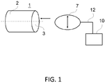
- this illustrates the method to apply an electric insulation to a retaining ring by means of an inflatable bag.
- Fig. 1 shows a schematic view of a retaining ring 1 at the left.
- the retaining ring 1 is mainly composed of a retaining ring housing 2 which is fabricated as a cylinder from massive steel alloy.
- the retaining ring 1 commonly encloses end windings of huge electric machines when assembled, as turbogenerators.
- An electric insulation 3 is attached to the inside of the retaining ring housing 2.
- the electric insulation 3 serves as means to preclude short circuits.
- the electric insulation 3 is made from a multi-layer fiberglass. At least one layer of the multi-layer fiberglass is covered with polytetrafluoroethylene.
- a layer of glue in particular a hot curing resin, is applied to the inside of the retaining ring housing 2.
- the glue has a heat resistance of up to 90° in this example.
- the electric insulation 3 is applied to the faces inside the retaining ring 1 onto the layer of glue to stick the electric insulation 3 to the retaining ring housing 2.
- An inflatable bag 7 is provided at the place of manufacture or maintenance of the retaining ring 1.
- This inflatable bag 7 comprises a chloroprene tissue of two or more layers which are glued to form one unity. Further materials for the inflatable bag 7 can be provided which are stable, have a sufficient resiliency, and are easy to ship to the place for maintenance of the retaining ring 1.
- the inflatable bag 7 has an opening to connect an inlet tube 12 from the outside.
- the inlet tube 12 is connected to a compressor 10 at the other end.
- the compressor 10 pumps and draws air into and from the inflatable bag 7 and by this inflates or deflates the bag 7, respectively.
- the compressor 10 can also pump a different gaseous medium into the bag 7.
- the inflatable bag 3 is inserted into the retaining ring 1 when the diameter of the bag 7 is smaller than the diameter of the retaining ring 1 and when the bag 7 is merely partly inflated.
- the insertion direction of the bag 7 into the retaining ring 1 is illustrated by the left arrow. This allows the operator to comfortably place the lightweight bag 7 into the retaining ring 1 manually.
- the inflatable bag 7 fills the complete space inside the retaining ring 1 then.
- the surface of the bag 7 abuts the applied electric insulation 3 at the inside of the retaining ring housing 2.
- the operator activates the compressor 10 such that compressed air is conducted under pressure through the inlet tube 12 and the opening in the bag 7 into the bag 7.
- the compressor 10 exerts a pressure of several bars to the inside of the bag 7.
- the pressure created by the compressor 10 is adjustable up to nine bars, although also higher pressures can be created. Consequently, the inflatable bag 7 increases the volume, the elastic material of the bag 7 expands. This expansion of the bag 7 is illustrated by the double-ended arrow inside the bag 7.
- the bag 7 presses to the outside in the radial direction, the created pressure is transferred to the electric insulation 3, the glue, and the wall of the retaining ring housing 2.
- the exerted pressure is necessary to enable a durable and safe bonding of the electric insulation 3 to the retaining ring housing 2.
- the pressure in the bag 7 is kept over a time of several hours.
- the electric insulation 3 is securely fixed nearly inseparably to the inside of the retaining ring 1.
- the bond is fabricated reliably due to high operation requirements to the rotating rotor and the retaining ring 1.
- the operator activates the compressor 10 to reduce the pressure to the bag 7 to deflate the bag 7.
- the inflatable bag 7 is removed without difficulty from the finished retaining ring 1 by the operator in the next operation step.
- the described method is especially useful in maintenance work on retaining rings 1 when replacing the electric insulation 3 by a new one.
- the compressor 10 and the inflatable bag 7 are easy to handle by the operator, in particular easy and cheap to transport.
Landscapes
- Engineering & Computer Science (AREA)
- Power Engineering (AREA)
- Manufacturing & Machinery (AREA)
- Insulation, Fastening Of Motor, Generator Windings (AREA)
- Manufacture Of Motors, Generators (AREA)
Abstract
Description
- The present disclosure relates to a method to apply an insulation to a retaining ring for end windings of an electric machine and to the use of an inflatable bag to apply an insulation to a retaining ring.
- Retaining rings are commonly fixed to end parts of the coils or windings of rotors of high power electric machines. The retaining rings mainly serve to mechanically stabilize the end parts, also referred to as end windings. The main parts of the windings are housed in the rotor slots, the end windings of the rotor however protrude outside of the slots and are in the case of high power generators bent in relation to the main winding part. To this end the retaining ring is fabricated as massive cylinder which encloses the end windings. Some retaining rings are internally insulated. The insulation is an electric insulation and consists of several layers of fibreglass with a layer thickness in the range of millimeters. The insulation layers can further be teflonized, i.e. a layer of polytetrafluoroethylene can be applied. The insulation layers are attached at the inside of the retaining ring by gluing with hot curing resin. Presently, with the need to replace the insulation of the retaining ring expensive tools are used. These tools are expansible steel cones or cylinders depending on the geometry of the retaining ring. The expansible steel cones or cylinders exert a pressure to the inside of the retaining ring with applied insulation. This high pressure is necessary to obtain a sufficient bond between the two different materials of the retaining ring and the insulation.
- It is an object of the invention to simplify the application of an insulation to a retaining ring of an electric machine. This object is solved with the features of a method to apply an insulation to a retaining ring and with the features to use an inflatable bag to apply a pressure to an insulation of a retaining ring according to the independent claims.
- According to the invention a method is disclosed to apply an insulation to a retaining ring for end windings of an electric machine, with the steps of providing a retaining ring housing, attaching an insulation at the inside of the retaining ring housing, and inflating a bag inside the retaining ring housing to apply pressure to the insulation. Further, die invention discloses the use of an inflatable bag to apply a pressure to an insulation inside a retaining ring for end windings of an electric machine.
- Further examples of the invention are disclosed in the dependent claims.
- In an example of the invention the bag comprises a chloroprene tissue. This material has the advantage to be particularly suitable in terms of tensile strength and stability. In a further related example the bag is fabricated from chloroprene tissue with at least two glued layers. This measure among others improves the relevant material properties. In another example the glue is a bonding resin.
- In a further example of the invention the bag is pressed against the insulation inside the retaining ring with a pressure of below nine bars by means of inflating the bag.
-
- Fig. 1
- shows a schematic view of a retaining ring with an insulation at the inside, a compressor which fills an inflatable bag with air via an inlet tube, with the inflatable bag to be inserted into the retaining ring.
- With reference to the figure, this illustrates the method to apply an electric insulation to a retaining ring by means of an inflatable bag.
-
Fig. 1 shows a schematic view of aretaining ring 1 at the left. Theretaining ring 1 is mainly composed of aretaining ring housing 2 which is fabricated as a cylinder from massive steel alloy. Theretaining ring 1 commonly encloses end windings of huge electric machines when assembled, as turbogenerators. Anelectric insulation 3 is attached to the inside of theretaining ring housing 2. Theelectric insulation 3 serves as means to preclude short circuits. Theelectric insulation 3 is made from a multi-layer fiberglass. At least one layer of the multi-layer fiberglass is covered with polytetrafluoroethylene. First, a layer of glue, in particular a hot curing resin, is applied to the inside of theretaining ring housing 2. The glue has a heat resistance of up to 90° in this example. Next, theelectric insulation 3 is applied to the faces inside theretaining ring 1 onto the layer of glue to stick theelectric insulation 3 to theretaining ring housing 2. Aninflatable bag 7 is provided at the place of manufacture or maintenance of theretaining ring 1. Thisinflatable bag 7 comprises a chloroprene tissue of two or more layers which are glued to form one unity. Further materials for theinflatable bag 7 can be provided which are stable, have a sufficient resiliency, and are easy to ship to the place for maintenance of theretaining ring 1. Theinflatable bag 7 has an opening to connect aninlet tube 12 from the outside. Theinlet tube 12 is connected to acompressor 10 at the other end. Via theinlet tube 12 thecompressor 10 pumps and draws air into and from theinflatable bag 7 and by this inflates or deflates thebag 7, respectively. Thecompressor 10 can also pump a different gaseous medium into thebag 7. Theinflatable bag 3 is inserted into theretaining ring 1 when the diameter of thebag 7 is smaller than the diameter of theretaining ring 1 and when thebag 7 is merely partly inflated. The insertion direction of thebag 7 into theretaining ring 1 is illustrated by the left arrow. This allows the operator to comfortably place thelightweight bag 7 into theretaining ring 1 manually. Theinflatable bag 7 fills the complete space inside theretaining ring 1 then. The surface of thebag 7 abuts the appliedelectric insulation 3 at the inside of theretaining ring housing 2. The operator activates thecompressor 10 such that compressed air is conducted under pressure through theinlet tube 12 and the opening in thebag 7 into thebag 7. Thecompressor 10 exerts a pressure of several bars to the inside of thebag 7. The pressure created by thecompressor 10 is adjustable up to nine bars, although also higher pressures can be created. Consequently, theinflatable bag 7 increases the volume, the elastic material of thebag 7 expands. This expansion of thebag 7 is illustrated by the double-ended arrow inside thebag 7. Thebag 7 presses to the outside in the radial direction, the created pressure is transferred to theelectric insulation 3, the glue, and the wall of the retainingring housing 2. The exerted pressure is necessary to enable a durable and safe bonding of theelectric insulation 3 to the retainingring housing 2. Depending on the used glue, a hot curing resin, the pressure in thebag 7 is kept over a time of several hours. When the glue is thoroughly cured theelectric insulation 3 is securely fixed nearly inseparably to the inside of theretaining ring 1. The bond is fabricated reliably due to high operation requirements to the rotating rotor and theretaining ring 1. The operator activates thecompressor 10 to reduce the pressure to thebag 7 to deflate thebag 7. Thus reduced the diameter the material of thebag 7 releases from theelectric insulation 3 at the inside surface of the retainingring 1. Theinflatable bag 7 is removed without difficulty from the finished retainingring 1 by the operator in the next operation step. The described method is especially useful in maintenance work on retainingrings 1 when replacing theelectric insulation 3 by a new one. Thecompressor 10 and theinflatable bag 7 are easy to handle by the operator, in particular easy and cheap to transport. - While the invention has been described in detail with reference to exemplary embodiments thereof, it will be apparent to one skilled in the art that various changes can be made, and equivalents employed, without departing from the scope of the invention. The foregoing description of the preferred embodiments of the invention has been presented for purposes of illustration and description. It is not intended to be exhaustive or to limit the invention to the precise form disclosed, and modifications and variations are possible in light of the above teachings or may be acquired from practice of the invention. The embodiments were chosen and described in order to explain the principles of the invention and its practical application to enable one skilled in the art to utilize the invention in various embodiments as are suited to the particular use contemplated. It is intended that the scope of the invention be defined by the claims appended hereto, and their equivalents.
-
- 1
- retaining ring
- 2
- retaining ring housing
- 3
- electric insulation
- 7
- bag
- 10
- compressor
- 12
- inlet tube
Claims (6)
- A method to apply an insulation to a retaining ring (1) for end windings of an electric machine, with the steps of providing a retaining ring housing (2), attaching an insulation (3) at the inside of the retaining ring housing (2), and inflating a bag (7) inside the retaining ring housing (2) to apply pressure to the insulation (3).
- The method according to claim 1, characterized in that the bag (7) comprises a chloroprene tissue.
- The method according to claim 2, characterized in fabricating the bag (7) from chloroprene tissue with at least two glued layers.
- The method according to claim 3, characterized in that the glue is a bonding resin.
- The method according to one of the foregoing claims, characterized in pressing the bag (7) against the electric insulation (3) inside the retaining ring (1) with a pressure of below nine bar.
- Use of an inflatable bag (7) to apply a pressure to an electric insulation (3) inside a retaining ring (1) for end windings of an electric machine.
Priority Applications (3)
| Application Number | Priority Date | Filing Date | Title |
|---|---|---|---|
| EP16158910.6A EP3217519B1 (en) | 2016-03-07 | 2016-03-07 | A method to apply an insulation |
| US15/438,279 US10560006B2 (en) | 2016-03-07 | 2017-02-21 | Method to apply an insulation |
| JP2017029593A JP2017163827A (en) | 2016-03-07 | 2017-02-21 | How to apply insulation |
Applications Claiming Priority (1)
| Application Number | Priority Date | Filing Date | Title |
|---|---|---|---|
| EP16158910.6A EP3217519B1 (en) | 2016-03-07 | 2016-03-07 | A method to apply an insulation |
Publications (2)
| Publication Number | Publication Date |
|---|---|
| EP3217519A1 true EP3217519A1 (en) | 2017-09-13 |
| EP3217519B1 EP3217519B1 (en) | 2018-10-03 |
Family
ID=55524165
Family Applications (1)
| Application Number | Title | Priority Date | Filing Date |
|---|---|---|---|
| EP16158910.6A Active EP3217519B1 (en) | 2016-03-07 | 2016-03-07 | A method to apply an insulation |
Country Status (3)
| Country | Link |
|---|---|
| US (1) | US10560006B2 (en) |
| EP (1) | EP3217519B1 (en) |
| JP (1) | JP2017163827A (en) |
Families Citing this family (1)
| Publication number | Priority date | Publication date | Assignee | Title |
|---|---|---|---|---|
| DE102022212976A1 (en) * | 2022-12-01 | 2024-06-06 | Robert Bosch Gesellschaft mit beschränkter Haftung | Stator arrangement and method for producing a stator arrangement |
Citations (5)
| Publication number | Priority date | Publication date | Assignee | Title |
|---|---|---|---|---|
| GB832100A (en) * | 1956-07-23 | 1960-04-06 | Westinghouse Elecctric Corp | Improvements in or relating to laminated structures |
| US3034479A (en) * | 1957-10-17 | 1962-05-15 | Larsh | Apparatus for flow coating the slots of a slotted stator |
| CA1009289A (en) * | 1974-01-11 | 1977-04-26 | Hugh O. Lorch | Dynamo-electric machine rotor with end turn support |
| US5415892A (en) * | 1992-04-21 | 1995-05-16 | Kabushiki Kaisha Toshiba | Method of impregnating a winding assembly of an electrical equipment with varnish |
| GB2403074A (en) * | 2003-06-21 | 2004-12-22 | Alstom Technology Ltd | Method or removing a retaining ring incorporating a drilling step. |
Family Cites Families (6)
| Publication number | Priority date | Publication date | Assignee | Title |
|---|---|---|---|---|
| JPS5534896A (en) * | 1979-08-06 | 1980-03-11 | Mitsubishi Electric Corp | Insulating method of rotor |
| DE19547251C2 (en) * | 1995-12-18 | 1999-10-14 | Vem Elektroantriebe Gmbh | Method and device for compressing a winding head insulation of an electrical machine |
| JP2001238375A (en) * | 2000-02-22 | 2001-08-31 | Moric Co Ltd | Permanent magnet field motor and permanent magnet fixing method |
| JP2003274619A (en) * | 2002-03-12 | 2003-09-26 | Furukawa Electric Co Ltd:The | Method of forming coil for motor |
| US20110123785A1 (en) * | 2009-11-20 | 2011-05-26 | Arturo Verduzco Garcia | Non-latex laminated balloons containing pigment and related methods |
| JP5710329B2 (en) | 2011-03-24 | 2015-04-30 | 株式会社東芝 | Armature winding of rotating electric machine |
-
2016
- 2016-03-07 EP EP16158910.6A patent/EP3217519B1/en active Active
-
2017
- 2017-02-21 JP JP2017029593A patent/JP2017163827A/en not_active Ceased
- 2017-02-21 US US15/438,279 patent/US10560006B2/en not_active Expired - Fee Related
Patent Citations (5)
| Publication number | Priority date | Publication date | Assignee | Title |
|---|---|---|---|---|
| GB832100A (en) * | 1956-07-23 | 1960-04-06 | Westinghouse Elecctric Corp | Improvements in or relating to laminated structures |
| US3034479A (en) * | 1957-10-17 | 1962-05-15 | Larsh | Apparatus for flow coating the slots of a slotted stator |
| CA1009289A (en) * | 1974-01-11 | 1977-04-26 | Hugh O. Lorch | Dynamo-electric machine rotor with end turn support |
| US5415892A (en) * | 1992-04-21 | 1995-05-16 | Kabushiki Kaisha Toshiba | Method of impregnating a winding assembly of an electrical equipment with varnish |
| GB2403074A (en) * | 2003-06-21 | 2004-12-22 | Alstom Technology Ltd | Method or removing a retaining ring incorporating a drilling step. |
Also Published As
| Publication number | Publication date |
|---|---|
| EP3217519B1 (en) | 2018-10-03 |
| US20170257011A1 (en) | 2017-09-07 |
| JP2017163827A (en) | 2017-09-14 |
| US10560006B2 (en) | 2020-02-11 |
Similar Documents
| Publication | Publication Date | Title |
|---|---|---|
| JP6804883B2 (en) | Reducing the link ring of contoured hat-type stiffeners formed from a single composite charge | |
| US9217463B2 (en) | Shaft of a gas-turbine engine, in particular a radial shaft or a shaft arranged at an angle to the machine axis | |
| JP3978235B2 (en) | Modular stator core and manufacturing method thereof | |
| ES2744470T3 (en) | Rolling mandrel having a variable shape and method of using it | |
| EP2540484B1 (en) | Method for repairing a member comprising a fiber-reinforced resin | |
| JP2010528899A (en) | Fiber composite structural member processing apparatus and fiber composite structural member processing method | |
| CN110049879A (en) | Fixation device for spoke and shear band attachment with the precompressed non-inflatable tyre of spoke | |
| US9211684B2 (en) | Method for manufacturing a shaft of a gas-turbine engine, in particular a radial shaft or a shaft arranged at an angle to the machine axis | |
| CA2384593C (en) | High temperature superconducting racetrack coil | |
| EP3217519B1 (en) | A method to apply an insulation | |
| US20220143933A1 (en) | Flexible thermoplastic composite coupling and method of manufacture | |
| EP0311400B1 (en) | Process and equipment for making composite tubes | |
| US3999912A (en) | Means for molding fiber reinforced composite tube | |
| TW201115026A (en) | Screw spindle machine and method of manufacturing the same | |
| US8668857B1 (en) | High quality out-of-autoclave composites | |
| US11894166B2 (en) | Manufacturing process for surge arrestor module using compaction bladder system | |
| JPH07299829A (en) | Molding method and molding die for hollow fiber-reinforced thermoplastic resin body | |
| CN203317339U (en) | Hot sleeve pressurizing device of shaft and sleeve | |
| GB2388479A (en) | Permanent magnet rotor assembly suitable for mounting on a turbine shaft | |
| EP2228197B1 (en) | Apparatus and method of manufacturing a composite tubular using a stiffened mandrel | |
| EP2860858A1 (en) | Manufacturing method of a conductor bar | |
| EP1054497A3 (en) | Method of manufacturing a component for a rotating machine, and a rotor including such components | |
| US20230386709A1 (en) | Manufacturing process for surge arrestor module using compaction bladder system | |
| CN210062073U (en) | A piston bonding Teflon curing tool | |
| CN223578509U (en) | Connecting rod for automobile inflator pump |
Legal Events
| Date | Code | Title | Description |
|---|---|---|---|
| PUAI | Public reference made under article 153(3) epc to a published international application that has entered the european phase |
Free format text: ORIGINAL CODE: 0009012 |
|
| STAA | Information on the status of an ep patent application or granted ep patent |
Free format text: STATUS: THE APPLICATION HAS BEEN PUBLISHED |
|
| AK | Designated contracting states |
Kind code of ref document: A1 Designated state(s): AL AT BE BG CH CY CZ DE DK EE ES FI FR GB GR HR HU IE IS IT LI LT LU LV MC MK MT NL NO PL PT RO RS SE SI SK SM TR |
|
| AX | Request for extension of the european patent |
Extension state: BA ME |
|
| STAA | Information on the status of an ep patent application or granted ep patent |
Free format text: STATUS: REQUEST FOR EXAMINATION WAS MADE |
|
| 17P | Request for examination filed |
Effective date: 20180313 |
|
| RBV | Designated contracting states (corrected) |
Designated state(s): AL AT BE BG CH CY CZ DE DK EE ES FI FR GB GR HR HU IE IS IT LI LT LU LV MC MK MT NL NO PL PT RO RS SE SI SK SM TR |
|
| RIC1 | Information provided on ipc code assigned before grant |
Ipc: H02K 3/38 20060101ALN20180326BHEP Ipc: H02K 15/12 20060101ALI20180326BHEP Ipc: H02K 3/51 20060101ALI20180326BHEP Ipc: H02K 15/10 20060101ALI20180326BHEP Ipc: H02K 15/00 20060101AFI20180326BHEP |
|
| RIC1 | Information provided on ipc code assigned before grant |
Ipc: H02K 3/51 20060101ALI20180416BHEP Ipc: H02K 3/38 20060101ALN20180416BHEP Ipc: H02K 15/10 20060101ALI20180416BHEP Ipc: H02K 15/00 20060101AFI20180416BHEP Ipc: H02K 15/12 20060101ALI20180416BHEP |
|
| GRAP | Despatch of communication of intention to grant a patent |
Free format text: ORIGINAL CODE: EPIDOSNIGR1 |
|
| STAA | Information on the status of an ep patent application or granted ep patent |
Free format text: STATUS: GRANT OF PATENT IS INTENDED |
|
| RIC1 | Information provided on ipc code assigned before grant |
Ipc: H02K 3/38 20060101ALN20180508BHEP Ipc: H02K 15/00 20060101AFI20180508BHEP Ipc: H02K 15/12 20060101ALI20180508BHEP Ipc: H02K 3/51 20060101ALI20180508BHEP Ipc: H02K 15/10 20060101ALI20180508BHEP |
|
| INTG | Intention to grant announced |
Effective date: 20180530 |
|
| GRAS | Grant fee paid |
Free format text: ORIGINAL CODE: EPIDOSNIGR3 |
|
| GRAA | (expected) grant |
Free format text: ORIGINAL CODE: 0009210 |
|
| STAA | Information on the status of an ep patent application or granted ep patent |
Free format text: STATUS: THE PATENT HAS BEEN GRANTED |
|
| AK | Designated contracting states |
Kind code of ref document: B1 Designated state(s): AL AT BE BG CH CY CZ DE DK EE ES FI FR GB GR HR HU IE IS IT LI LT LU LV MC MK MT NL NO PL PT RO RS SE SI SK SM TR |
|
| REG | Reference to a national code |
Ref country code: GB Ref legal event code: FG4D |
|
| REG | Reference to a national code |
Ref country code: CH Ref legal event code: EP Ref country code: AT Ref legal event code: REF Ref document number: 1049690 Country of ref document: AT Kind code of ref document: T Effective date: 20181015 |
|
| REG | Reference to a national code |
Ref country code: IE Ref legal event code: FG4D Ref country code: DE Ref legal event code: R096 Ref document number: 602016006130 Country of ref document: DE |
|
| REG | Reference to a national code |
Ref country code: NL Ref legal event code: MP Effective date: 20181003 |
|
| REG | Reference to a national code |
Ref country code: LT Ref legal event code: MG4D |
|
| REG | Reference to a national code |
Ref country code: AT Ref legal event code: MK05 Ref document number: 1049690 Country of ref document: AT Kind code of ref document: T Effective date: 20181003 |
|
| PG25 | Lapsed in a contracting state [announced via postgrant information from national office to epo] |
Ref country code: NL Free format text: LAPSE BECAUSE OF FAILURE TO SUBMIT A TRANSLATION OF THE DESCRIPTION OR TO PAY THE FEE WITHIN THE PRESCRIBED TIME-LIMIT Effective date: 20181003 |
|
| PG25 | Lapsed in a contracting state [announced via postgrant information from national office to epo] |
Ref country code: BG Free format text: LAPSE BECAUSE OF FAILURE TO SUBMIT A TRANSLATION OF THE DESCRIPTION OR TO PAY THE FEE WITHIN THE PRESCRIBED TIME-LIMIT Effective date: 20190103 Ref country code: FI Free format text: LAPSE BECAUSE OF FAILURE TO SUBMIT A TRANSLATION OF THE DESCRIPTION OR TO PAY THE FEE WITHIN THE PRESCRIBED TIME-LIMIT Effective date: 20181003 Ref country code: PL Free format text: LAPSE BECAUSE OF FAILURE TO SUBMIT A TRANSLATION OF THE DESCRIPTION OR TO PAY THE FEE WITHIN THE PRESCRIBED TIME-LIMIT Effective date: 20181003 Ref country code: LT Free format text: LAPSE BECAUSE OF FAILURE TO SUBMIT A TRANSLATION OF THE DESCRIPTION OR TO PAY THE FEE WITHIN THE PRESCRIBED TIME-LIMIT Effective date: 20181003 Ref country code: HR Free format text: LAPSE BECAUSE OF FAILURE TO SUBMIT A TRANSLATION OF THE DESCRIPTION OR TO PAY THE FEE WITHIN THE PRESCRIBED TIME-LIMIT Effective date: 20181003 Ref country code: LV Free format text: LAPSE BECAUSE OF FAILURE TO SUBMIT A TRANSLATION OF THE DESCRIPTION OR TO PAY THE FEE WITHIN THE PRESCRIBED TIME-LIMIT Effective date: 20181003 Ref country code: ES Free format text: LAPSE BECAUSE OF FAILURE TO SUBMIT A TRANSLATION OF THE DESCRIPTION OR TO PAY THE FEE WITHIN THE PRESCRIBED TIME-LIMIT Effective date: 20181003 Ref country code: CZ Free format text: LAPSE BECAUSE OF FAILURE TO SUBMIT A TRANSLATION OF THE DESCRIPTION OR TO PAY THE FEE WITHIN THE PRESCRIBED TIME-LIMIT Effective date: 20181003 Ref country code: AT Free format text: LAPSE BECAUSE OF FAILURE TO SUBMIT A TRANSLATION OF THE DESCRIPTION OR TO PAY THE FEE WITHIN THE PRESCRIBED TIME-LIMIT Effective date: 20181003 Ref country code: IS Free format text: LAPSE BECAUSE OF FAILURE TO SUBMIT A TRANSLATION OF THE DESCRIPTION OR TO PAY THE FEE WITHIN THE PRESCRIBED TIME-LIMIT Effective date: 20190203 Ref country code: NO Free format text: LAPSE BECAUSE OF FAILURE TO SUBMIT A TRANSLATION OF THE DESCRIPTION OR TO PAY THE FEE WITHIN THE PRESCRIBED TIME-LIMIT Effective date: 20190103 |
|
| PG25 | Lapsed in a contracting state [announced via postgrant information from national office to epo] |
Ref country code: PT Free format text: LAPSE BECAUSE OF FAILURE TO SUBMIT A TRANSLATION OF THE DESCRIPTION OR TO PAY THE FEE WITHIN THE PRESCRIBED TIME-LIMIT Effective date: 20190203 Ref country code: GR Free format text: LAPSE BECAUSE OF FAILURE TO SUBMIT A TRANSLATION OF THE DESCRIPTION OR TO PAY THE FEE WITHIN THE PRESCRIBED TIME-LIMIT Effective date: 20190104 Ref country code: SE Free format text: LAPSE BECAUSE OF FAILURE TO SUBMIT A TRANSLATION OF THE DESCRIPTION OR TO PAY THE FEE WITHIN THE PRESCRIBED TIME-LIMIT Effective date: 20181003 Ref country code: RS Free format text: LAPSE BECAUSE OF FAILURE TO SUBMIT A TRANSLATION OF THE DESCRIPTION OR TO PAY THE FEE WITHIN THE PRESCRIBED TIME-LIMIT Effective date: 20181003 Ref country code: AL Free format text: LAPSE BECAUSE OF FAILURE TO SUBMIT A TRANSLATION OF THE DESCRIPTION OR TO PAY THE FEE WITHIN THE PRESCRIBED TIME-LIMIT Effective date: 20181003 |
|
| REG | Reference to a national code |
Ref country code: DE Ref legal event code: R097 Ref document number: 602016006130 Country of ref document: DE |
|
| PG25 | Lapsed in a contracting state [announced via postgrant information from national office to epo] |
Ref country code: IT Free format text: LAPSE BECAUSE OF FAILURE TO SUBMIT A TRANSLATION OF THE DESCRIPTION OR TO PAY THE FEE WITHIN THE PRESCRIBED TIME-LIMIT Effective date: 20181003 Ref country code: DK Free format text: LAPSE BECAUSE OF FAILURE TO SUBMIT A TRANSLATION OF THE DESCRIPTION OR TO PAY THE FEE WITHIN THE PRESCRIBED TIME-LIMIT Effective date: 20181003 |
|
| PLBE | No opposition filed within time limit |
Free format text: ORIGINAL CODE: 0009261 |
|
| STAA | Information on the status of an ep patent application or granted ep patent |
Free format text: STATUS: NO OPPOSITION FILED WITHIN TIME LIMIT |
|
| PG25 | Lapsed in a contracting state [announced via postgrant information from national office to epo] |
Ref country code: SK Free format text: LAPSE BECAUSE OF FAILURE TO SUBMIT A TRANSLATION OF THE DESCRIPTION OR TO PAY THE FEE WITHIN THE PRESCRIBED TIME-LIMIT Effective date: 20181003 Ref country code: SM Free format text: LAPSE BECAUSE OF FAILURE TO SUBMIT A TRANSLATION OF THE DESCRIPTION OR TO PAY THE FEE WITHIN THE PRESCRIBED TIME-LIMIT Effective date: 20181003 Ref country code: EE Free format text: LAPSE BECAUSE OF FAILURE TO SUBMIT A TRANSLATION OF THE DESCRIPTION OR TO PAY THE FEE WITHIN THE PRESCRIBED TIME-LIMIT Effective date: 20181003 Ref country code: RO Free format text: LAPSE BECAUSE OF FAILURE TO SUBMIT A TRANSLATION OF THE DESCRIPTION OR TO PAY THE FEE WITHIN THE PRESCRIBED TIME-LIMIT Effective date: 20181003 |
|
| 26N | No opposition filed |
Effective date: 20190704 |
|
| PG25 | Lapsed in a contracting state [announced via postgrant information from national office to epo] |
Ref country code: MC Free format text: LAPSE BECAUSE OF FAILURE TO SUBMIT A TRANSLATION OF THE DESCRIPTION OR TO PAY THE FEE WITHIN THE PRESCRIBED TIME-LIMIT Effective date: 20181003 Ref country code: SI Free format text: LAPSE BECAUSE OF FAILURE TO SUBMIT A TRANSLATION OF THE DESCRIPTION OR TO PAY THE FEE WITHIN THE PRESCRIBED TIME-LIMIT Effective date: 20181003 |
|
| REG | Reference to a national code |
Ref country code: CH Ref legal event code: PL |
|
| PG25 | Lapsed in a contracting state [announced via postgrant information from national office to epo] |
Ref country code: LU Free format text: LAPSE BECAUSE OF NON-PAYMENT OF DUE FEES Effective date: 20190307 |
|
| REG | Reference to a national code |
Ref country code: BE Ref legal event code: MM Effective date: 20190331 |
|
| PG25 | Lapsed in a contracting state [announced via postgrant information from national office to epo] |
Ref country code: LI Free format text: LAPSE BECAUSE OF NON-PAYMENT OF DUE FEES Effective date: 20190331 Ref country code: CH Free format text: LAPSE BECAUSE OF NON-PAYMENT OF DUE FEES Effective date: 20190331 Ref country code: IE Free format text: LAPSE BECAUSE OF NON-PAYMENT OF DUE FEES Effective date: 20190307 |
|
| PG25 | Lapsed in a contracting state [announced via postgrant information from national office to epo] |
Ref country code: BE Free format text: LAPSE BECAUSE OF NON-PAYMENT OF DUE FEES Effective date: 20190331 |
|
| PG25 | Lapsed in a contracting state [announced via postgrant information from national office to epo] |
Ref country code: TR Free format text: LAPSE BECAUSE OF FAILURE TO SUBMIT A TRANSLATION OF THE DESCRIPTION OR TO PAY THE FEE WITHIN THE PRESCRIBED TIME-LIMIT Effective date: 20181003 |
|
| PG25 | Lapsed in a contracting state [announced via postgrant information from national office to epo] |
Ref country code: MT Free format text: LAPSE BECAUSE OF NON-PAYMENT OF DUE FEES Effective date: 20190307 |
|
| PG25 | Lapsed in a contracting state [announced via postgrant information from national office to epo] |
Ref country code: CY Free format text: LAPSE BECAUSE OF FAILURE TO SUBMIT A TRANSLATION OF THE DESCRIPTION OR TO PAY THE FEE WITHIN THE PRESCRIBED TIME-LIMIT Effective date: 20181003 |
|
| PG25 | Lapsed in a contracting state [announced via postgrant information from national office to epo] |
Ref country code: HU Free format text: LAPSE BECAUSE OF FAILURE TO SUBMIT A TRANSLATION OF THE DESCRIPTION OR TO PAY THE FEE WITHIN THE PRESCRIBED TIME-LIMIT; INVALID AB INITIO Effective date: 20160307 |
|
| PGFP | Annual fee paid to national office [announced via postgrant information from national office to epo] |
Ref country code: DE Payment date: 20220217 Year of fee payment: 7 |
|
| PGFP | Annual fee paid to national office [announced via postgrant information from national office to epo] |
Ref country code: FR Payment date: 20220221 Year of fee payment: 7 |
|
| PG25 | Lapsed in a contracting state [announced via postgrant information from national office to epo] |
Ref country code: MK Free format text: LAPSE BECAUSE OF FAILURE TO SUBMIT A TRANSLATION OF THE DESCRIPTION OR TO PAY THE FEE WITHIN THE PRESCRIBED TIME-LIMIT Effective date: 20181003 |
|
| P01 | Opt-out of the competence of the unified patent court (upc) registered |
Effective date: 20230523 |
|
| REG | Reference to a national code |
Ref country code: DE Ref legal event code: R119 Ref document number: 602016006130 Country of ref document: DE |
|
| PG25 | Lapsed in a contracting state [announced via postgrant information from national office to epo] |
Ref country code: FR Free format text: LAPSE BECAUSE OF NON-PAYMENT OF DUE FEES Effective date: 20230331 Ref country code: DE Free format text: LAPSE BECAUSE OF NON-PAYMENT OF DUE FEES Effective date: 20231003 |
|
| PGFP | Annual fee paid to national office [announced via postgrant information from national office to epo] |
Ref country code: GB Payment date: 20250221 Year of fee payment: 10 |