EP3217478A1 - Screwless terminal block - Google Patents
Screwless terminal block Download PDFInfo
- Publication number
- EP3217478A1 EP3217478A1 EP16204919.1A EP16204919A EP3217478A1 EP 3217478 A1 EP3217478 A1 EP 3217478A1 EP 16204919 A EP16204919 A EP 16204919A EP 3217478 A1 EP3217478 A1 EP 3217478A1
- Authority
- EP
- European Patent Office
- Prior art keywords
- fixture
- point
- wire
- housing
- insertion opening
- Prior art date
- Legal status (The legal status is an assumption and is not a legal conclusion. Google has not performed a legal analysis and makes no representation as to the accuracy of the status listed.)
- Granted
Links
Images



Classifications
-
- H—ELECTRICITY
- H01—ELECTRIC ELEMENTS
- H01R—ELECTRICALLY-CONDUCTIVE CONNECTIONS; STRUCTURAL ASSOCIATIONS OF A PLURALITY OF MUTUALLY-INSULATED ELECTRICAL CONNECTING ELEMENTS; COUPLING DEVICES; CURRENT COLLECTORS
- H01R4/00—Electrically-conductive connections between two or more conductive members in direct contact, i.e. touching one another; Means for effecting or maintaining such contact; Electrically-conductive connections having two or more spaced connecting locations for conductors and using contact members penetrating insulation
- H01R4/28—Clamped connections, spring connections
- H01R4/48—Clamped connections, spring connections utilising a spring, clip, or other resilient member
- H01R4/4809—Clamped connections, spring connections utilising a spring, clip, or other resilient member using a leaf spring to bias the conductor toward the busbar
- H01R4/48185—Clamped connections, spring connections utilising a spring, clip, or other resilient member using a leaf spring to bias the conductor toward the busbar adapted for axial insertion of a wire end
- H01R4/4819—Clamped connections, spring connections utilising a spring, clip, or other resilient member using a leaf spring to bias the conductor toward the busbar adapted for axial insertion of a wire end the spring shape allowing insertion of the conductor end when the spring is unbiased
- H01R4/4821—Single-blade spring
-
- H—ELECTRICITY
- H01—ELECTRIC ELEMENTS
- H01R—ELECTRICALLY-CONDUCTIVE CONNECTIONS; STRUCTURAL ASSOCIATIONS OF A PLURALITY OF MUTUALLY-INSULATED ELECTRICAL CONNECTING ELEMENTS; COUPLING DEVICES; CURRENT COLLECTORS
- H01R9/00—Structural associations of a plurality of mutually-insulated electrical connecting elements, e.g. terminal strips or terminal blocks; Terminals or binding posts mounted upon a base or in a case; Bases therefor
- H01R9/22—Bases, e.g. strip, block, panel
- H01R9/24—Terminal blocks
-
- H—ELECTRICITY
- H01—ELECTRIC ELEMENTS
- H01R—ELECTRICALLY-CONDUCTIVE CONNECTIONS; STRUCTURAL ASSOCIATIONS OF A PLURALITY OF MUTUALLY-INSULATED ELECTRICAL CONNECTING ELEMENTS; COUPLING DEVICES; CURRENT COLLECTORS
- H01R4/00—Electrically-conductive connections between two or more conductive members in direct contact, i.e. touching one another; Means for effecting or maintaining such contact; Electrically-conductive connections having two or more spaced connecting locations for conductors and using contact members penetrating insulation
- H01R4/28—Clamped connections, spring connections
- H01R4/48—Clamped connections, spring connections utilising a spring, clip, or other resilient member
-
- H—ELECTRICITY
- H01—ELECTRIC ELEMENTS
- H01R—ELECTRICALLY-CONDUCTIVE CONNECTIONS; STRUCTURAL ASSOCIATIONS OF A PLURALITY OF MUTUALLY-INSULATED ELECTRICAL CONNECTING ELEMENTS; COUPLING DEVICES; CURRENT COLLECTORS
- H01R13/00—Details of coupling devices of the kinds covered by groups H01R12/70 or H01R24/00 - H01R33/00
- H01R13/62—Means for facilitating engagement or disengagement of coupling parts or for holding them in engagement
-
- H—ELECTRICITY
- H01—ELECTRIC ELEMENTS
- H01R—ELECTRICALLY-CONDUCTIVE CONNECTIONS; STRUCTURAL ASSOCIATIONS OF A PLURALITY OF MUTUALLY-INSULATED ELECTRICAL CONNECTING ELEMENTS; COUPLING DEVICES; CURRENT COLLECTORS
- H01R13/00—Details of coupling devices of the kinds covered by groups H01R12/70 or H01R24/00 - H01R33/00
- H01R13/62—Means for facilitating engagement or disengagement of coupling parts or for holding them in engagement
- H01R13/629—Additional means for facilitating engagement or disengagement of coupling parts, e.g. aligning or guiding means, levers, gas pressure electrical locking indicators, manufacturing tolerances
- H01R13/633—Additional means for facilitating engagement or disengagement of coupling parts, e.g. aligning or guiding means, levers, gas pressure electrical locking indicators, manufacturing tolerances for disengagement only
- H01R13/635—Additional means for facilitating engagement or disengagement of coupling parts, e.g. aligning or guiding means, levers, gas pressure electrical locking indicators, manufacturing tolerances for disengagement only by mechanical pressure, e.g. spring force
-
- H—ELECTRICITY
- H01—ELECTRIC ELEMENTS
- H01R—ELECTRICALLY-CONDUCTIVE CONNECTIONS; STRUCTURAL ASSOCIATIONS OF A PLURALITY OF MUTUALLY-INSULATED ELECTRICAL CONNECTING ELEMENTS; COUPLING DEVICES; CURRENT COLLECTORS
- H01R4/00—Electrically-conductive connections between two or more conductive members in direct contact, i.e. touching one another; Means for effecting or maintaining such contact; Electrically-conductive connections having two or more spaced connecting locations for conductors and using contact members penetrating insulation
- H01R4/28—Clamped connections, spring connections
- H01R4/48—Clamped connections, spring connections utilising a spring, clip, or other resilient member
- H01R4/4809—Clamped connections, spring connections utilising a spring, clip, or other resilient member using a leaf spring to bias the conductor toward the busbar
- H01R4/484—Spring housing details
- H01R4/4842—Spring housing details the spring housing being provided with a single opening for insertion of a spring-activating tool
-
- H—ELECTRICITY
- H01—ELECTRIC ELEMENTS
- H01R—ELECTRICALLY-CONDUCTIVE CONNECTIONS; STRUCTURAL ASSOCIATIONS OF A PLURALITY OF MUTUALLY-INSULATED ELECTRICAL CONNECTING ELEMENTS; COUPLING DEVICES; CURRENT COLLECTORS
- H01R9/00—Structural associations of a plurality of mutually-insulated electrical connecting elements, e.g. terminal strips or terminal blocks; Terminals or binding posts mounted upon a base or in a case; Bases therefor
- H01R9/22—Bases, e.g. strip, block, panel
- H01R9/24—Terminal blocks
- H01R9/2416—Means for guiding or retaining wires or cables connected to terminal blocks
Definitions
- the present invention relates to a screwless terminal block.
- Screwless terminal blocks known in the art allow connection of wires to terminal blocks without using screws.
- Patent Literature 1 describes a screwless terminal including a contact pressure spring for fixing wires and a release button.
- the screwless terminal described in Patent Literature 1 has its release button pressed using a screwdriver and then the release button presses the contact pressure spring to allow insertion and removal of the wires.
- Patent Literature 1 Japanese Unexamined Patent Application Publication No. 2000-251968 (published on September 14, 2000 )
- one or more aspects of the present invention are directed to a screwless terminal block that allows easy insertion and removal of a wire.
- a screwless terminal block includes a resin housing having a wire insertion opening through which a wire is to be inserted, and an internal wire accommodating space to accommodate the wire, and an elastic member that comes in contact with the wire inserted through the wire insertion opening and applies a force to the wire in a predetermined pressing direction to prevent the wire from coming off.
- the housing has a fixture insertion opening through which a rod-like fixture is to be inserted to come in contact with the elastic member and cause the elastic member to deform away from the wire accommodating space.
- an acute angle of 45° or less is formed by an axis of the fixture and a straight line connecting a point A and a point B at a cross-section taken along a plane that includes the axis of the fixture and is parallel to the predetermined pressing direction.
- the point A is a point of contact between the housing and a part of the fixture adjacent to the wire insertion opening.
- the point B is a point of contact between the housing and a part of the fixture adjacent to the elastic member.
- the fixture receives a force from the elastic member to rotate about point A. However, the fixture, which is in contact with the housing at the point B, applies a force to the housing at the point B.
- the structure described above provides a longer distance between a plane X, which includes the point A and is perpendicular to the axial direction of the fixture, and the point B. This reduces the force at the point B applied from the fixture and received by the housing, and reduces distortion or deformation of the housing at the point B.
- the screwless terminal block can support the fixture in a stable manner at the points A and B, and the point of contact between the elastic member and the fixture. The insertion or removal of a wire is easy.
- the screwless terminal block according to the aspect of the present invention may be any screwless terminal block that includes the housing and the elastic member described above, and may have various structures.
- the screwless terminal block according to the embodiment may be an input and output unit including the housing and the elastic member described above and incorporated in a device such as a relay, a relay socket, a temperature regulator, or a power supply.
- the elastic member applies a force of 30 N or less to the fixture inserted through the fixture insertion opening.
- the above structure allows the fixture to be inserted through the fixture insertion opening and to easily deform the elastic member.
- the above structure allows the pressure at the point B applied from the fixture and received by the housing to be equal to or less than the compressive strength of the resin used for the housing, and further reduces distortion or deformation of the housing at the point B. This allows the screwless terminal block to support the fixture in a more stable manner.
- a screwless terminal block includes a resin housing having a wire insertion opening through which a wire is to be inserted, and an elastic member that comes in contact with the wire inserted through the wire insertion opening and apply a force to the wire in a predetermined pressing direction to prevent the wire from coming off.
- the housing has a fixture insertion opening through which a rod-like fixture is to be inserted to come in contact with the elastic member and deform the elastic member away from the wire.
- the above structure allows the pressure at the point B applied from the fixture and received by the housing to be equal to or less than the compressive strength of the resin used for the housing, and reduces distortion or deformation of the housing at the point B.
- This allows the screwless terminal block to support the fixture in a more stable manner.
- the screwless terminal block can support the fixture in a stable manner at the points A and B, and the point of contact between the elastic member and the fixture. Thus, the insertion or removal of a wire is easy.
- the housing has a curved surface with a curvature of an outer periphery of the fixture, and the point B is included in the curved surface.
- the above structure reduces the pressure at the point B to be applied by the fixture to the housing, and further reduces distortion or deformation of the housing at the point B.
- the screwless terminal block can support the fixture in a more stable manner.
- the screwless terminal block allows easy insertion or removal of wires.
- Fig. 1 is a schematic perspective view of a screwless terminal block 1 according to an embodiment of the present invention.
- the screwless terminal block 1 includes a housing 2.
- the housing 2 has wire insertion openings 24, through which wires are to be inserted, and fixture insertion openings 23, through which fixtures are to be inserted when the wires are inserted or removed.
- the screwless terminal block 1 according to the present embodiment has four pairs of wire insertion openings 24 and fixture insertion openings 23.
- the numbers of wire insertion openings 24 and fixture insertion openings 23 are not limited to these.
- the screwless terminal block 1 shown in Fig. 1 is separate from other parts, the screwless terminal block according to the embodiment is not limited to this structure.
- the screwless terminal block according to the embodiment may be a terminal block as an input and output unit incorporated in a device such as a relay, a relay socket, a temperature regulator, or a power supply.
- Figs. 2 to 4 are cross-sectional views of the screwless terminal block 1 taken along a plane including one pair of the wire insertion opening 24 and the fixture insertion opening 23.
- Fig. 2 shows the screwless terminal block 1 with no wire 5 being inserted
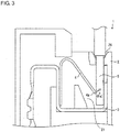
- Fig. 3 shows the screwless terminal block 1 with a wire 5 being inserted
- Fig. 4 shows the screwless terminal block 1 with a fixture 6 being inserted for allowing insertion or removal of the wire 5.
- the direction in which the wire 5 is inserted is downward, and the direction in which the wire 5 is removed is upward.
- the screwless terminal block 1 includes a housing unit 21 in the housing 2.
- the housing unit 21 includes a terminal base 3 and a contact pressure spring 4.
- the housing 2 is formed from a resin, such as modified polyphenylene ether (PPE) or polyamide 66 (PA66).
- PPE modified polyphenylene ether
- PA66 polyamide 66
- the fixture insertion opening 23 is a hole communicating with the housing unit 21, through which a rod-like fixture 6 is inserted for inserting or removing the wire 5.
- the fixture 6 may be, for example, a slotted screwdriver.
- the wire insertion opening 24 is a hole communicating with the housing unit 21, through which the wire 5 is inserted into the housing unit 21 in the housing 2.
- the housing unit 21 in the housing 2 has a wire accommodating space 21 c under the wire insertion opening 24.
- the wire accommodating space 21 c accommodates the wire 5 inserted through the wire insertion opening 24.
- the terminal base 3 is formed from a conductor.
- the terminal base 3 electrically connects to the wire 5 when the wire 5 is inserted.
- the terminal base 3 has a substantially U-shaped cross-section, and is arranged to come in contact with a bottom surface 21 a and a side surface 21 b of the housing unit 21.
- the contact pressure spring 4 is an elastic leaf spring. As shown in Fig. 3 , the contact pressure spring 4 presses the wire 5 against the terminal base 3 with a biasing force when the wire 5 is inserted. In the present embodiment, the tip end 4a of the contact pressure spring 4 comes in contact with the wire 5, and applies a force Fa in a pressing direction, which is direction a, to the wire 5. The wire 5 inserted through the wire insertion opening 24 is retained between the terminal base 3 and the contact pressure spring 4 and is prevented from coming off from the terminal block.
- the pressure spring 4 may have a shape different from the shape shown in Figs. 2 to 4 .
- the contact pressure spring 4 may have a curved portion adjacent to its tip end, and the curved portion may come in contact with the wire 5 and apply the force Fa in the pressing direction a.
- the screwless terminal block 1 can support the fixture 6 when the fixture 6 is inserted, without the worker holding the fixture 6. This structure will now be described with reference to Fig. 4 .
- the tip end of the fixture 6 comes in contact with the contact pressure spring 4.
- the worker further inserts the fixture 6 while compressing (or deforming) the contact pressure spring 4 away from the wire 5 (or from the wire accommodating space 21c when no wire 5 is inserted) until the fixture 6 comes in contact with the terminal base 3, which is in contact with the bottom surface 21 a of the housing unit 21.
- the fixture 6 tilts under the biasing force of the contact pressure spring 4. In this state, the fixture 6 is in contact with and supported by the screwless terminal block 1 at three points, or one point on the pressure spring 4 and two points on the wall surfaces of the fixture insertion opening 23 in the housing 2.
- the fixture 6 comes in contact with a point A, which is on a wall 23a adjacent to the wire insertion opening 24, and a point B, which is on a wall 23b adjacent to the contact pressure spring 4, among the walls defining the fixture insertion opening 23 in the housing 2, and a point C on the contact pressure spring 4.
- the fixture 6 is in contact with the housing 2 at the point A adjacent to the wire insertion opening 24, and at the point B adjacent to the contact pressure spring 4.
- the resin housing 2 receives an excessive force from the fixture 6 at the contact points between the housing 2 and the fixture 6 when the fixture 6 is supported at the three points, and may distort or deform to destabilize supporting of the fixture 6.
- the inventors have then conceived the structure according to the embodiment.
- the walls 23a and 23b defining the fixture insertion opening 23 in the housing 2 are designed to have an acute angle of 45° or less, or 40° or less between the axis of the rod-like fixture 6 and the straight line connecting the points A and B.
- the contact pressure spring 4 applies a force Fc to the fixture 6 in substantially the same direction as the pressing direction a (specifically, the direction toward the wire 5).
- the surface of the fixture 6 adjacent to the wire insertion opening 24 comes in contact with the housing 2 at the point A to cause the fixture 6 to rotate about the point A.
- the surface of the fixture 6 adjacent to the contact pressure spring 4 is in contact with the housing 2 at the point B.
- the fixture 6 applies a force Fb to the housing 2 at the point B.
- the housing 2 is formed from a resin, and thus may distort or deform when receiving, at the point B, a pressure larger than the compressive strength of the resin.
- the distortion or deformation of the housing 2 may destabilize supporting of the fixture 6 at the points A, B, and C, and may cause the fixture 6 to come off easily from the screwless terminal block 1. In this case, the worker is not allowed to remove his or her hand from the fixture 6 while inserting or removing the wire. This work is difficult and complicated.
- the housing 2 according to the present embodiment is designed to have an acute angle of 45° or less, or 40° or less between the axis of the rod-like fixture 6 and the straight line connecting the points A and B.
- This structure provides a longer distance between a plane X, which includes the point A and is perpendicular to the axial direction of the fixture 6, and the point B (in other words, the length of the perpendicular line from the point B to the plane X).
- the distance b between the plane X and the point B may be set longer to reduce the force Fb, which presses the housing 2 at the point B.
- the longer distance between the plane X and the point B thus reduces distortion or deformation of the housing 2 at the point B.
- the screwless terminal block 1 can support the fixture 6 in a stable manner at the points A, B, and C. The worker is allowed to remove his or her hand from the fixture 6 when inserting or removing the wire 5. This work is easy.
- a slotted screwdriver with a shaft diameter of 2.5 mm is used as the fixture 6, the force Fc applied to the fixture 6 by the contact pressure spring 4 is set equal to or less than 30 N, and the distance c between the plane X and the point C is set at 5.8 mm.
- typical modified PPE or typical PA66 is used as a resin for the housing 2
- the compressive strength is in a range of 70 to 90 MPa.
- the force Fb (N) to be applied to the housing 2 at the point B is 30 x (5.8/b) at the maximum.
- the pressure (MPa) is 30 x (5.8/b) at the point B.
- a slotted screwdriver with a shaft diameter of 2.5 mm is used as the fixture 6, the force Fc applied to the fixture 6 by the contact pressure spring 4 is set equal to or less than 27 N, and the distance c between the plane X and the point C is set at 7.7 mm.
- the force Fb (N) to be applied to the housing 2 at the point B is 27 x (7.7/b) at the maximum.
- the pressure (MPa) is 27 x (7.7/b) at the point B.
- the components of the screwless terminal block 1 in the present embodiment are set to allow the pressure applied at the point B to be equal to or less than the compressive strength of the resin used for the housing 2.
- the structure according to the embodiment of the present invention is designed to satisfy the inequality Fc x (c/b) ⁇ 70, where b is the distance between the point B and the plane X, which includes the point A and is perpendicular to the axial direction of the fixture 6, c is the distance between the plane X and the point C, and Fc is the force applied to the fixture 6 by the contact pressure spring 4.
- the force Fc may be 30 N or less to allow insertion or removal of the fixture 6, and thus c/b ⁇ 70/30.
- the housing 2 may have a curved surface having the curvature of the outer periphery of the fixture 6 around the point B. This allows the point B to be included in the curved surface, and allows the force applied by the fixture 6 to be received by the entire curved surface with a larger area than the area of the point B. This lowers the pressure at the point B.
Landscapes
- Connections Arranged To Contact A Plurality Of Conductors (AREA)
- Manufacturing Of Electrical Connectors (AREA)
- Connector Housings Or Holding Contact Members (AREA)
Abstract
Description
- The present invention relates to a screwless terminal block.
- Screwless terminal blocks known in the art allow connection of wires to terminal blocks without using screws.
- For example,
Patent Literature 1 describes a screwless terminal including a contact pressure spring for fixing wires and a release button. The screwless terminal described inPatent Literature 1 has its release button pressed using a screwdriver and then the release button presses the contact pressure spring to allow insertion and removal of the wires. - Patent Literature 1: Japanese Unexamined Patent Application Publication No.
2000-251968 (published on September 14, 2000 - However, the worker uses both hands when inserting or removing a wire into and from the screwless terminal described in
Patent Literature 1. To insert or remove a wire, the worker holds a screwdriver on one hand and the wire on the other hand, and presses the release button using the screwdriver, and then inserts or removes the wire while pressing the release button. The worker then releases the release button to complete this operation. In this manner, the worker uses both hands when inserting or removing a wire into or from the screwless terminal described inPatent Literature 1. This work is difficult and complicated. - In response to the above issue, one or more aspects of the present invention are directed to a screwless terminal block that allows easy insertion and removal of a wire.
- In response to the above issue, a screwless terminal block according to one aspect of the present invention includes a resin housing having a wire insertion opening through which a wire is to be inserted, and an internal wire accommodating space to accommodate the wire, and an elastic member that comes in contact with the wire inserted through the wire insertion opening and applies a force to the wire in a predetermined pressing direction to prevent the wire from coming off. The housing has a fixture insertion opening through which a rod-like fixture is to be inserted to come in contact with the elastic member and cause the elastic member to deform away from the wire accommodating space. When the fixture is inserted through the fixture insertion opening, an acute angle of 45° or less is formed by an axis of the fixture and a straight line connecting a point A and a point B at a cross-section taken along a plane that includes the axis of the fixture and is parallel to the predetermined pressing direction. The point A is a point of contact between the housing and a part of the fixture adjacent to the wire insertion opening. The point B is a point of contact between the housing and a part of the fixture adjacent to the elastic member.
- The fixture receives a force from the elastic member to rotate about point A. However, the fixture, which is in contact with the housing at the point B, applies a force to the housing at the point B. The structure described above provides a longer distance between a plane X, which includes the point A and is perpendicular to the axial direction of the fixture, and the point B. This reduces the force at the point B applied from the fixture and received by the housing, and reduces distortion or deformation of the housing at the point B. Thus, the screwless terminal block can support the fixture in a stable manner at the points A and B, and the point of contact between the elastic member and the fixture. The insertion or removal of a wire is easy.
- The screwless terminal block according to the aspect of the present invention may be any screwless terminal block that includes the housing and the elastic member described above, and may have various structures. For example, the screwless terminal block according to the embodiment may be an input and output unit including the housing and the elastic member described above and incorporated in a device such as a relay, a relay socket, a temperature regulator, or a power supply.
- In the screwless terminal block according to another aspect of the present invention, the elastic member applies a force of 30 N or less to the fixture inserted through the fixture insertion opening.
- The above structure allows the fixture to be inserted through the fixture insertion opening and to easily deform the elastic member.
- In the screwless terminal block according to another aspect of the present invention, when the fixture is inserted through the fixture insertion opening, c/b ≤ 7/3, where b is a distance between the point B and a plane X that includes the point A and is perpendicular to the axis of the fixture, and c is a distance between the plane X and a point C that is a point of contact between the fixture and the elastic member.
- The above structure allows the pressure at the point B applied from the fixture and received by the housing to be equal to or less than the compressive strength of the resin used for the housing, and further reduces distortion or deformation of the housing at the point B. This allows the screwless terminal block to support the fixture in a more stable manner.
- A screwless terminal block according to another aspect of the present invention includes a resin housing having a wire insertion opening through which a wire is to be inserted, and an elastic member that comes in contact with the wire inserted through the wire insertion opening and apply a force to the wire in a predetermined pressing direction to prevent the wire from coming off. The housing has a fixture insertion opening through which a rod-like fixture is to be inserted to come in contact with the elastic member and deform the elastic member away from the wire. When the fixture is inserted through the fixture insertion opening, c/b ≤ 70/Fc at a cross-section taken along a plane that includes an axis of the fixture and is parallel to the predetermined pressing direction, where b is a distance between a point B and a plane X that includes a point A and is perpendicular to the axis of the fixture, c is a distance between the plane X and a point C, and Fc (N) is a force applied from the elastic member and received by the fixture, and the point A is a point of contact between the housing and a part of the fixture adjacent to the wire insertion opening, the point B is a point of contact between the housing and a part of the fixture adjacent to the elastic member, and the point C is a point of contact between the fixture and the elastic member.
- The above structure allows the pressure at the point B applied from the fixture and received by the housing to be equal to or less than the compressive strength of the resin used for the housing, and reduces distortion or deformation of the housing at the point B. This allows the screwless terminal block to support the fixture in a more stable manner. The screwless terminal block can support the fixture in a stable manner at the points A and B, and the point of contact between the elastic member and the fixture. Thus, the insertion or removal of a wire is easy.
- In the screwless terminal block according to another aspect of the present invention, the housing has a curved surface with a curvature of an outer periphery of the fixture, and the point B is included in the curved surface.
- The above structure reduces the pressure at the point B to be applied by the fixture to the housing, and further reduces distortion or deformation of the housing at the point B. Thus, the screwless terminal block can support the fixture in a more stable manner.
- The screwless terminal block according to one or more embodiments of the present invention allows easy insertion or removal of wires.
-
-
Fig. 1 is a schematic perspective view of a screwless terminal block according to an embodiment of the present invention. -
Fig. 2 is a cross-sectional view of the screwless terminal block shown inFig. 1 with no wire being inserted. -
Fig. 3 is a cross-sectional view of the screwless terminal block shown inFig. 1 with a wire being inserted. -
Fig. 4 is a cross-sectional view of the screwless terminal block shown inFig. 1 with a fixture being inserted. - Embodiments of the present invention will now be described in detail with reference to the drawings.
-
Fig. 1 is a schematic perspective view of ascrewless terminal block 1 according to an embodiment of the present invention. As shown inFig. 1 , thescrewless terminal block 1 includes ahousing 2. Thehousing 2 haswire insertion openings 24, through which wires are to be inserted, andfixture insertion openings 23, through which fixtures are to be inserted when the wires are inserted or removed. As shown inFig. 1 , thescrewless terminal block 1 according to the present embodiment has four pairs ofwire insertion openings 24 andfixture insertion openings 23. However, the numbers ofwire insertion openings 24 andfixture insertion openings 23 are not limited to these. - Although the
screwless terminal block 1 shown inFig. 1 is separate from other parts, the screwless terminal block according to the embodiment is not limited to this structure. For example, the screwless terminal block according to the embodiment may be a terminal block as an input and output unit incorporated in a device such as a relay, a relay socket, a temperature regulator, or a power supply. -
Figs. 2 to 4 are cross-sectional views of thescrewless terminal block 1 taken along a plane including one pair of the wire insertion opening 24 and the fixture insertion opening 23.Fig. 2 shows thescrewless terminal block 1 with nowire 5 being inserted, whereasFig. 3 shows thescrewless terminal block 1 with awire 5 being inserted.Fig. 4 shows thescrewless terminal block 1 with afixture 6 being inserted for allowing insertion or removal of thewire 5. For ease of explanation herein, the direction in which thewire 5 is inserted is downward, and the direction in which thewire 5 is removed is upward. - The
screwless terminal block 1 includes ahousing unit 21 in thehousing 2. Thehousing unit 21 includes aterminal base 3 and acontact pressure spring 4. - The
housing 2 is formed from a resin, such as modified polyphenylene ether (PPE) or polyamide 66 (PA66). Thehousing 2 has thefixture insertion openings 23 and thewire insertion openings 24 as described above. - As shown in
Fig. 4 , thefixture insertion opening 23 is a hole communicating with thehousing unit 21, through which a rod-like fixture 6 is inserted for inserting or removing thewire 5. Thefixture 6 may be, for example, a slotted screwdriver. - The
wire insertion opening 24 is a hole communicating with thehousing unit 21, through which thewire 5 is inserted into thehousing unit 21 in thehousing 2. Thehousing unit 21 in thehousing 2 has awire accommodating space 21 c under thewire insertion opening 24. Thewire accommodating space 21 c accommodates thewire 5 inserted through thewire insertion opening 24. - The
terminal base 3 is formed from a conductor. Theterminal base 3 electrically connects to thewire 5 when thewire 5 is inserted. Theterminal base 3 has a substantially U-shaped cross-section, and is arranged to come in contact with abottom surface 21 a and aside surface 21 b of thehousing unit 21. - The
contact pressure spring 4 is an elastic leaf spring. As shown inFig. 3 , thecontact pressure spring 4 presses thewire 5 against theterminal base 3 with a biasing force when thewire 5 is inserted. In the present embodiment, thetip end 4a of thecontact pressure spring 4 comes in contact with thewire 5, and applies a force Fa in a pressing direction, which is direction a, to thewire 5. Thewire 5 inserted through thewire insertion opening 24 is retained between theterminal base 3 and thecontact pressure spring 4 and is prevented from coming off from the terminal block. - The
pressure spring 4 may have a shape different from the shape shown inFigs. 2 to 4 . For example, thecontact pressure spring 4 may have a curved portion adjacent to its tip end, and the curved portion may come in contact with thewire 5 and apply the force Fa in the pressing direction a. - The screwless
terminal block 1 according to the present embodiment can support thefixture 6 when thefixture 6 is inserted, without the worker holding thefixture 6. This structure will now be described with reference toFig. 4 . - When the worker inserts the
fixture 6 into thehousing unit 21 through thefixture insertion opening 23, the tip end of thefixture 6 comes in contact with thecontact pressure spring 4. The worker further inserts thefixture 6 while compressing (or deforming) thecontact pressure spring 4 away from the wire 5 (or from thewire accommodating space 21c when nowire 5 is inserted) until thefixture 6 comes in contact with theterminal base 3, which is in contact with thebottom surface 21 a of thehousing unit 21. When the worker removes his or her hand from thefixture 6 in this state, thefixture 6 tilts under the biasing force of thecontact pressure spring 4. In this state, thefixture 6 is in contact with and supported by the screwlessterminal block 1 at three points, or one point on thepressure spring 4 and two points on the wall surfaces of thefixture insertion opening 23 in thehousing 2. - At the cross-section shown in
Fig. 4 taken along a plane including the axis of the rod-like fixture 6 and parallel to the pressing direction a of thecontact pressure spring 4, thefixture 6 comes in contact with a point A, which is on awall 23a adjacent to thewire insertion opening 24, and a point B, which is on awall 23b adjacent to thecontact pressure spring 4, among the walls defining thefixture insertion opening 23 in thehousing 2, and a point C on thecontact pressure spring 4. In other words, thefixture 6 is in contact with thehousing 2 at the point A adjacent to thewire insertion opening 24, and at the point B adjacent to thecontact pressure spring 4. - The inventors have noticed that the
resin housing 2 receives an excessive force from thefixture 6 at the contact points between thehousing 2 and thefixture 6 when thefixture 6 is supported at the three points, and may distort or deform to destabilize supporting of thefixture 6. The inventors have then conceived the structure according to the embodiment. - To achieve more stable supporting of the
fixture 6 at the three points, thewalls fixture insertion opening 23 in thehousing 2 are designed to have an acute angle of 45° or less, or 40° or less between the axis of the rod-like fixture 6 and the straight line connecting the points A and B. - As shown in
Fig. 4 , when thefixture 6 is inserted into thefixture insertion opening 23, thecontact pressure spring 4 applies a force Fc to thefixture 6 in substantially the same direction as the pressing direction a (specifically, the direction toward the wire 5). The surface of thefixture 6 adjacent to thewire insertion opening 24 comes in contact with thehousing 2 at the point A to cause thefixture 6 to rotate about the point A. However, the surface of thefixture 6 adjacent to thecontact pressure spring 4 is in contact with thehousing 2 at the point B. In response to the force Fc applied to thefixture 6 at the point C, thefixture 6 applies a force Fb to thehousing 2 at the point B. Thehousing 2 is formed from a resin, and thus may distort or deform when receiving, at the point B, a pressure larger than the compressive strength of the resin. The distortion or deformation of thehousing 2 may destabilize supporting of thefixture 6 at the points A, B, and C, and may cause thefixture 6 to come off easily from the screwlessterminal block 1. In this case, the worker is not allowed to remove his or her hand from thefixture 6 while inserting or removing the wire. This work is difficult and complicated. - In contrast, the
housing 2 according to the present embodiment is designed to have an acute angle of 45° or less, or 40° or less between the axis of the rod-like fixture 6 and the straight line connecting the points A and B. This structure provides a longer distance between a plane X, which includes the point A and is perpendicular to the axial direction of thefixture 6, and the point B (in other words, the length of the perpendicular line from the point B to the plane X). The force Fb to be applied to thehousing 2 at the point B (wall 23b) can be calculated approximately using the formula Fb = Fc x (c/b), using the distance b between the plane X and the point B, and the distance c between the plane X and the point C (specifically, the perpendicular line from the point C to the plane X). Thus, the distance b between the plane X and the point B may be set longer to reduce the force Fb, which presses thehousing 2 at the point B. The longer distance between the plane X and the point B thus reduces distortion or deformation of thehousing 2 at the point B. The screwlessterminal block 1 can support thefixture 6 in a stable manner at the points A, B, and C. The worker is allowed to remove his or her hand from thefixture 6 when inserting or removing thewire 5. This work is easy. - In one example, a slotted screwdriver with a shaft diameter of 2.5 mm is used as the
fixture 6, the force Fc applied to thefixture 6 by thecontact pressure spring 4 is set equal to or less than 30 N, and the distance c between the plane X and the point C is set at 5.8 mm. When typical modified PPE or typical PA66 is used as a resin for thehousing 2, the compressive strength is in a range of 70 to 90 MPa. In this case, the force Fb (N) to be applied to thehousing 2 at the point B is 30 x (5.8/b) at the maximum. Assuming that the force Fb is applied to an area of 1 mm2, the pressure (MPa) is 30 x (5.8/b) at the point B. To maintain the pressure to be equal to or less than the compressive strength of the resin used for thehousing 2, the inequality 30 x (5.8/b) ≤ 70 is to be satisfied, and thus b ≥ 2.5. An angle θ formed by the straight line connecting the points A and B and the axis of thefixture 6 is written as θ ≤ atan (the minimum value of 2.5 of the shaft diameter of 2.5/b of the fixture 6) ≈ 45°. Thus, with the acute angle of 45° or less between the straight line connecting the points A and B and the axis of the rod-like fixture 6, the pressure to be applied at the point B can be equal to or less than the compressive strength of the resin used for thehousing 2. - In another example, a slotted screwdriver with a shaft diameter of 2.5 mm is used as the
fixture 6, the force Fc applied to thefixture 6 by thecontact pressure spring 4 is set equal to or less than 27 N, and the distance c between the plane X and the point C is set at 7.7 mm. In this case, the force Fb (N) to be applied to thehousing 2 at the point B is 27 x (7.7/b) at the maximum. Assuming that the force Fb is applied to an area of 1 mm2, the pressure (MPa) is 27 x (7.7/b) at the point B. To maintain this pressure to be equal to or less than the compressive strength of the resin used for thehousing 2, the inequality 27 x (7.7/b) ≤ 70 is to be satisfied, and thus b ≥ 3.0. An angle θ formed by the straight line connecting the points A and B and the axis of thefixture 6 is written as θ ≤ atan (the minimum value of 3.0 of the shaft diameter of 2.5/b of the fixture 6) ≈ 40°. Thus, with the acute angle of 40° or less between the straight line connecting the points A and B and the axis of the rod-like fixture 6, the pressure to be applied at the point B can be equal to or less than the compressive strength of the resin used for thehousing 2. - In this manner, the components of the screwless
terminal block 1 in the present embodiment are set to allow the pressure applied at the point B to be equal to or less than the compressive strength of the resin used for thehousing 2. In other words, the structure according to the embodiment of the present invention is designed to satisfy the inequality Fc x (c/b) ≤ 70, where b is the distance between the point B and the plane X, which includes the point A and is perpendicular to the axial direction of thefixture 6, c is the distance between the plane X and the point C, and Fc is the force applied to thefixture 6 by thecontact pressure spring 4. The force Fc may be 30 N or less to allow insertion or removal of thefixture 6, and thus c/b ≤ 70/30. - The
housing 2 may have a curved surface having the curvature of the outer periphery of thefixture 6 around the point B. This allows the point B to be included in the curved surface, and allows the force applied by thefixture 6 to be received by the entire curved surface with a larger area than the area of the point B. This lowers the pressure at the point B. - The embodiments disclosed herein should not be construed to be restrictive, but may be modified within the spirit and scope of the claimed invention. The technical features disclosed in different embodiments may be combined in other embodiments within the technical scope of the invention.
-
- 1
- terminal block
- 2
- housing
- 3
- terminal base
- 4
- contact pressure spring (elastic member)
- 5
- wire
- 6
- fixture
- 21c
- wire accommodating space
- 23
- fixture insertion opening
- 24
- wire insertion opening
Claims (4)
- A screwless terminal block, comprising:a resin housing having a wire insertion opening through which a wire is to be inserted, and an internal wire accommodating space configured to accommodate the wire; andan elastic member configured to come in contact with the wire inserted through the wire insertion opening and apply a force to the wire in a predetermined pressing direction to prevent the wire from coming off,the housing having a fixture insertion opening through which a rod-like fixture is to be inserted to come in contact with the elastic member and deform the elastic member away from the wire accommodating space,wherein when the fixture is inserted through the fixture insertion opening, an acute angle of 45° or less is formed by an axis of the fixture and a straight line connecting a point A and a point B at a cross-section taken along a plane that includes the axis of the fixture and is parallel to the predetermined pressing direction, where the point A is a point of contact between the housing and a part of the fixture adjacent to the wire insertion opening, and the point B is a point of contact between the housing and a part of the fixture adjacent to the elastic member.
- The screwless terminal block according to claim 1, wherein the elastic member is configured to apply a force of 30 N or less to the fixture inserted through the fixture insertion opening.
- The screwless terminal block according to claim 2, wherein
when the fixture is inserted through the fixture insertion opening, c/b ≤ 7/3,
where b is a distance between the point B and a plane X that includes the point A and is perpendicular to the axis of the fixture, and c is a distance between the plane X and a point C that is a point of contact between the fixture and the elastic member. - The screwless terminal block according to any one of claims 1 to 3, wherein the housing has a curved surface with a curvature of an outer periphery of the fixture, and the point B is included in the curved surface.
Applications Claiming Priority (1)
| Application Number | Priority Date | Filing Date | Title |
|---|---|---|---|
| JP2016043864A JP6418183B2 (en) | 2016-03-07 | 2016-03-07 | Manufacturing method for screwless terminal blocks |
Publications (2)
| Publication Number | Publication Date |
|---|---|
| EP3217478A1 true EP3217478A1 (en) | 2017-09-13 |
| EP3217478B1 EP3217478B1 (en) | 2020-05-06 |
Family
ID=57708361
Family Applications (1)
| Application Number | Title | Priority Date | Filing Date |
|---|---|---|---|
| EP16204919.1A Active EP3217478B1 (en) | 2016-03-07 | 2016-12-19 | Screwless terminal block |
Country Status (5)
| Country | Link |
|---|---|
| US (1) | US9819121B2 (en) |
| EP (1) | EP3217478B1 (en) |
| JP (1) | JP6418183B2 (en) |
| KR (1) | KR101845638B1 (en) |
| CN (1) | CN107171081A (en) |
Families Citing this family (10)
| Publication number | Priority date | Publication date | Assignee | Title |
|---|---|---|---|---|
| JP2018107079A (en) * | 2016-12-28 | 2018-07-05 | オムロン株式会社 | Terminal block |
| EP3367508B1 (en) * | 2017-02-28 | 2019-07-24 | Omron Corporation | Terminal block |
| JP6988848B2 (en) * | 2018-03-14 | 2022-01-05 | オムロン株式会社 | Terminal block |
| TWI666836B (en) * | 2018-03-16 | 2019-07-21 | 進聯工業股份有限公司 | Structure of conductive component of electric wiring device |
| JP7203316B2 (en) * | 2019-02-25 | 2023-01-13 | パナソニックIpマネジメント株式会社 | sockets and lighting fixtures |
| KR102440027B1 (en) * | 2019-11-01 | 2022-09-06 | 미쓰비시덴키 가부시키가이샤 | magnetic contactor |
| JP7294100B2 (en) * | 2019-12-06 | 2023-06-20 | 富士電機機器制御株式会社 | Terminal connection unit |
| KR102099339B1 (en) | 2019-12-27 | 2020-04-09 | 추창범 | Terminal block for electric wire |
| JP7482832B2 (en) * | 2021-05-18 | 2024-05-14 | 三菱電機株式会社 | Stranded wire connection tool |
| JP7782283B2 (en) * | 2022-01-31 | 2025-12-09 | オムロン株式会社 | socket |
Citations (3)
| Publication number | Priority date | Publication date | Assignee | Title |
|---|---|---|---|---|
| US5494456A (en) * | 1994-10-03 | 1996-02-27 | Methode Electronics, Inc. | Wire-trap connector with anti-overstress member |
| US6074242A (en) * | 1998-12-31 | 2000-06-13 | Methode Electronics, Inc. | Wire-trap connector for solderless compression connection |
| JP2000251968A (en) | 1999-03-02 | 2000-09-14 | Nitto Electric Works Ltd | Screwless terminal |
Family Cites Families (6)
| Publication number | Priority date | Publication date | Assignee | Title |
|---|---|---|---|---|
| DE2700793A1 (en) * | 1977-01-11 | 1978-07-13 | Kleinhuis Fa H | Wire connection terminal block - has chamber with contact and clamping spring holding inserted wire |
| JP2585890Y2 (en) | 1992-03-13 | 1998-11-25 | 松下電工株式会社 | Quick connection terminal device |
| JPH0955238A (en) * | 1995-08-10 | 1997-02-25 | Shinko Seisakusho:Kk | Terminal device |
| DE10119652A1 (en) * | 2001-04-20 | 2002-11-14 | Wieland Electric Gmbh | Screwless connection terminal |
| US6746286B2 (en) * | 2002-03-06 | 2004-06-08 | Ideal Industries, Inc. | Push-in wire connector |
| TWI351799B (en) * | 2006-04-25 | 2011-11-01 | Wago Verwaltungs Gmbh | Elektr. verbinder |
-
2016
- 2016-03-07 JP JP2016043864A patent/JP6418183B2/en active Active
- 2016-12-05 KR KR1020160164180A patent/KR101845638B1/en active Active
- 2016-12-14 CN CN201611150374.7A patent/CN107171081A/en active Pending
- 2016-12-19 EP EP16204919.1A patent/EP3217478B1/en active Active
- 2016-12-19 US US15/382,842 patent/US9819121B2/en active Active
Patent Citations (3)
| Publication number | Priority date | Publication date | Assignee | Title |
|---|---|---|---|---|
| US5494456A (en) * | 1994-10-03 | 1996-02-27 | Methode Electronics, Inc. | Wire-trap connector with anti-overstress member |
| US6074242A (en) * | 1998-12-31 | 2000-06-13 | Methode Electronics, Inc. | Wire-trap connector for solderless compression connection |
| JP2000251968A (en) | 1999-03-02 | 2000-09-14 | Nitto Electric Works Ltd | Screwless terminal |
Also Published As
| Publication number | Publication date |
|---|---|
| KR101845638B1 (en) | 2018-04-04 |
| JP2017162579A (en) | 2017-09-14 |
| CN107171081A (en) | 2017-09-15 |
| KR20170104363A (en) | 2017-09-15 |
| JP6418183B2 (en) | 2018-11-07 |
| US9819121B2 (en) | 2017-11-14 |
| EP3217478B1 (en) | 2020-05-06 |
Similar Documents
| Publication | Publication Date | Title |
|---|---|---|
| EP3217478B1 (en) | Screwless terminal block | |
| US11355881B2 (en) | Electrical connector housing, electrical connector and electrical connector assembly | |
| US8303352B2 (en) | Contact clip | |
| JP5062863B2 (en) | Small round connector assembly | |
| KR20110063296A (en) | Terminal box for solar cell module | |
| WO2016147691A1 (en) | Probe pin and probe unit with same | |
| CN109121444B (en) | Spring contact pin | |
| JP2010212151A (en) | Connector | |
| JP2015056209A (en) | Electrical connector terminal and electrical connector | |
| JP4571964B2 (en) | Connection contacts for conductors | |
| CN105244653A (en) | Wiring terminal | |
| EP3547455A1 (en) | Conductive terminal and connector | |
| CN207947396U (en) | A wire transfer terminal | |
| US6705574B2 (en) | Cable mounting structure | |
| CN105164861B (en) | RF connectors with push-in connection | |
| CN112585836A (en) | Charging device | |
| US12027282B2 (en) | Arrangement for attaching an insulator sleeve to an electrical conductor | |
| EP2551708A1 (en) | Clamp terminal comprising adaptor and kit for assembling clamp terminal comprising adaptor | |
| TW200515022A (en) | Optical plug and mounting method thereof | |
| US9246244B2 (en) | RF connector with push-on connection | |
| CN212011336U (en) | Plug-in connector | |
| TWI703780B (en) | Coaxial cable connector, coaxial cable connector with carrier, and manufacturing method of coaxial cable connector | |
| CN105938947A (en) | Connecting tertminal | |
| CN113280952B (en) | Force measuring device for connector contact removal | |
| JP2025129691A (en) | Electronic control unit |
Legal Events
| Date | Code | Title | Description |
|---|---|---|---|
| PUAI | Public reference made under article 153(3) epc to a published international application that has entered the european phase |
Free format text: ORIGINAL CODE: 0009012 |
|
| STAA | Information on the status of an ep patent application or granted ep patent |
Free format text: STATUS: REQUEST FOR EXAMINATION WAS MADE |
|
| 17P | Request for examination filed |
Effective date: 20170109 |
|
| AK | Designated contracting states |
Kind code of ref document: A1 Designated state(s): AL AT BE BG CH CY CZ DE DK EE ES FI FR GB GR HR HU IE IS IT LI LT LU LV MC MK MT NL NO PL PT RO RS SE SI SK SM TR |
|
| AX | Request for extension of the european patent |
Extension state: BA ME |
|
| STAA | Information on the status of an ep patent application or granted ep patent |
Free format text: STATUS: EXAMINATION IS IN PROGRESS |
|
| 17Q | First examination report despatched |
Effective date: 20180202 |
|
| GRAP | Despatch of communication of intention to grant a patent |
Free format text: ORIGINAL CODE: EPIDOSNIGR1 |
|
| STAA | Information on the status of an ep patent application or granted ep patent |
Free format text: STATUS: GRANT OF PATENT IS INTENDED |
|
| RIC1 | Information provided on ipc code assigned before grant |
Ipc: H01R 4/48 20060101AFI20200128BHEP Ipc: H01R 9/24 20060101ALN20200128BHEP |
|
| INTG | Intention to grant announced |
Effective date: 20200217 |
|
| GRAS | Grant fee paid |
Free format text: ORIGINAL CODE: EPIDOSNIGR3 |
|
| GRAL | Information related to payment of fee for publishing/printing deleted |
Free format text: ORIGINAL CODE: EPIDOSDIGR3 |
|
| GRAS | Grant fee paid |
Free format text: ORIGINAL CODE: EPIDOSNIGR3 |
|
| GRAA | (expected) grant |
Free format text: ORIGINAL CODE: 0009210 |
|
| STAA | Information on the status of an ep patent application or granted ep patent |
Free format text: STATUS: THE PATENT HAS BEEN GRANTED |
|
| AK | Designated contracting states |
Kind code of ref document: B1 Designated state(s): AL AT BE BG CH CY CZ DE DK EE ES FI FR GB GR HR HU IE IS IT LI LT LU LV MC MK MT NL NO PL PT RO RS SE SI SK SM TR |
|
| REG | Reference to a national code |
Ref country code: GB Ref legal event code: FG4D |
|
| REG | Reference to a national code |
Ref country code: AT Ref legal event code: REF Ref document number: 1268339 Country of ref document: AT Kind code of ref document: T Effective date: 20200515 Ref country code: CH Ref legal event code: EP |
|
| REG | Reference to a national code |
Ref country code: IE Ref legal event code: FG4D |
|
| REG | Reference to a national code |
Ref country code: DE Ref legal event code: R096 Ref document number: 602016035626 Country of ref document: DE |
|
| REG | Reference to a national code |
Ref country code: LT Ref legal event code: MG4D |
|
| REG | Reference to a national code |
Ref country code: NL Ref legal event code: MP Effective date: 20200506 |
|
| PG25 | Lapsed in a contracting state [announced via postgrant information from national office to epo] |
Ref country code: IS Free format text: LAPSE BECAUSE OF FAILURE TO SUBMIT A TRANSLATION OF THE DESCRIPTION OR TO PAY THE FEE WITHIN THE PRESCRIBED TIME-LIMIT Effective date: 20200906 Ref country code: SE Free format text: LAPSE BECAUSE OF FAILURE TO SUBMIT A TRANSLATION OF THE DESCRIPTION OR TO PAY THE FEE WITHIN THE PRESCRIBED TIME-LIMIT Effective date: 20200506 Ref country code: FI Free format text: LAPSE BECAUSE OF FAILURE TO SUBMIT A TRANSLATION OF THE DESCRIPTION OR TO PAY THE FEE WITHIN THE PRESCRIBED TIME-LIMIT Effective date: 20200506 Ref country code: NO Free format text: LAPSE BECAUSE OF FAILURE TO SUBMIT A TRANSLATION OF THE DESCRIPTION OR TO PAY THE FEE WITHIN THE PRESCRIBED TIME-LIMIT Effective date: 20200806 Ref country code: GR Free format text: LAPSE BECAUSE OF FAILURE TO SUBMIT A TRANSLATION OF THE DESCRIPTION OR TO PAY THE FEE WITHIN THE PRESCRIBED TIME-LIMIT Effective date: 20200807 Ref country code: LT Free format text: LAPSE BECAUSE OF FAILURE TO SUBMIT A TRANSLATION OF THE DESCRIPTION OR TO PAY THE FEE WITHIN THE PRESCRIBED TIME-LIMIT Effective date: 20200506 Ref country code: PT Free format text: LAPSE BECAUSE OF FAILURE TO SUBMIT A TRANSLATION OF THE DESCRIPTION OR TO PAY THE FEE WITHIN THE PRESCRIBED TIME-LIMIT Effective date: 20200907 |
|
| PG25 | Lapsed in a contracting state [announced via postgrant information from national office to epo] |
Ref country code: HR Free format text: LAPSE BECAUSE OF FAILURE TO SUBMIT A TRANSLATION OF THE DESCRIPTION OR TO PAY THE FEE WITHIN THE PRESCRIBED TIME-LIMIT Effective date: 20200506 Ref country code: RS Free format text: LAPSE BECAUSE OF FAILURE TO SUBMIT A TRANSLATION OF THE DESCRIPTION OR TO PAY THE FEE WITHIN THE PRESCRIBED TIME-LIMIT Effective date: 20200506 Ref country code: LV Free format text: LAPSE BECAUSE OF FAILURE TO SUBMIT A TRANSLATION OF THE DESCRIPTION OR TO PAY THE FEE WITHIN THE PRESCRIBED TIME-LIMIT Effective date: 20200506 Ref country code: BG Free format text: LAPSE BECAUSE OF FAILURE TO SUBMIT A TRANSLATION OF THE DESCRIPTION OR TO PAY THE FEE WITHIN THE PRESCRIBED TIME-LIMIT Effective date: 20200806 |
|
| REG | Reference to a national code |
Ref country code: AT Ref legal event code: MK05 Ref document number: 1268339 Country of ref document: AT Kind code of ref document: T Effective date: 20200506 |
|
| PG25 | Lapsed in a contracting state [announced via postgrant information from national office to epo] |
Ref country code: NL Free format text: LAPSE BECAUSE OF FAILURE TO SUBMIT A TRANSLATION OF THE DESCRIPTION OR TO PAY THE FEE WITHIN THE PRESCRIBED TIME-LIMIT Effective date: 20200506 Ref country code: AL Free format text: LAPSE BECAUSE OF FAILURE TO SUBMIT A TRANSLATION OF THE DESCRIPTION OR TO PAY THE FEE WITHIN THE PRESCRIBED TIME-LIMIT Effective date: 20200506 |
|
| PG25 | Lapsed in a contracting state [announced via postgrant information from national office to epo] |
Ref country code: IT Free format text: LAPSE BECAUSE OF FAILURE TO SUBMIT A TRANSLATION OF THE DESCRIPTION OR TO PAY THE FEE WITHIN THE PRESCRIBED TIME-LIMIT Effective date: 20200506 Ref country code: CZ Free format text: LAPSE BECAUSE OF FAILURE TO SUBMIT A TRANSLATION OF THE DESCRIPTION OR TO PAY THE FEE WITHIN THE PRESCRIBED TIME-LIMIT Effective date: 20200506 Ref country code: RO Free format text: LAPSE BECAUSE OF FAILURE TO SUBMIT A TRANSLATION OF THE DESCRIPTION OR TO PAY THE FEE WITHIN THE PRESCRIBED TIME-LIMIT Effective date: 20200506 Ref country code: ES Free format text: LAPSE BECAUSE OF FAILURE TO SUBMIT A TRANSLATION OF THE DESCRIPTION OR TO PAY THE FEE WITHIN THE PRESCRIBED TIME-LIMIT Effective date: 20200506 Ref country code: EE Free format text: LAPSE BECAUSE OF FAILURE TO SUBMIT A TRANSLATION OF THE DESCRIPTION OR TO PAY THE FEE WITHIN THE PRESCRIBED TIME-LIMIT Effective date: 20200506 Ref country code: AT Free format text: LAPSE BECAUSE OF FAILURE TO SUBMIT A TRANSLATION OF THE DESCRIPTION OR TO PAY THE FEE WITHIN THE PRESCRIBED TIME-LIMIT Effective date: 20200506 Ref country code: SM Free format text: LAPSE BECAUSE OF FAILURE TO SUBMIT A TRANSLATION OF THE DESCRIPTION OR TO PAY THE FEE WITHIN THE PRESCRIBED TIME-LIMIT Effective date: 20200506 Ref country code: DK Free format text: LAPSE BECAUSE OF FAILURE TO SUBMIT A TRANSLATION OF THE DESCRIPTION OR TO PAY THE FEE WITHIN THE PRESCRIBED TIME-LIMIT Effective date: 20200506 |
|
| REG | Reference to a national code |
Ref country code: DE Ref legal event code: R097 Ref document number: 602016035626 Country of ref document: DE |
|
| PG25 | Lapsed in a contracting state [announced via postgrant information from national office to epo] |
Ref country code: PL Free format text: LAPSE BECAUSE OF FAILURE TO SUBMIT A TRANSLATION OF THE DESCRIPTION OR TO PAY THE FEE WITHIN THE PRESCRIBED TIME-LIMIT Effective date: 20200506 Ref country code: SK Free format text: LAPSE BECAUSE OF FAILURE TO SUBMIT A TRANSLATION OF THE DESCRIPTION OR TO PAY THE FEE WITHIN THE PRESCRIBED TIME-LIMIT Effective date: 20200506 |
|
| PLBE | No opposition filed within time limit |
Free format text: ORIGINAL CODE: 0009261 |
|
| STAA | Information on the status of an ep patent application or granted ep patent |
Free format text: STATUS: NO OPPOSITION FILED WITHIN TIME LIMIT |
|
| 26N | No opposition filed |
Effective date: 20210209 |
|
| PG25 | Lapsed in a contracting state [announced via postgrant information from national office to epo] |
Ref country code: SI Free format text: LAPSE BECAUSE OF FAILURE TO SUBMIT A TRANSLATION OF THE DESCRIPTION OR TO PAY THE FEE WITHIN THE PRESCRIBED TIME-LIMIT Effective date: 20200506 |
|
| REG | Reference to a national code |
Ref country code: CH Ref legal event code: PL |
|
| GBPC | Gb: european patent ceased through non-payment of renewal fee |
Effective date: 20201219 |
|
| PG25 | Lapsed in a contracting state [announced via postgrant information from national office to epo] |
Ref country code: MC Free format text: LAPSE BECAUSE OF FAILURE TO SUBMIT A TRANSLATION OF THE DESCRIPTION OR TO PAY THE FEE WITHIN THE PRESCRIBED TIME-LIMIT Effective date: 20200506 |
|
| REG | Reference to a national code |
Ref country code: BE Ref legal event code: MM Effective date: 20201231 |
|
| PG25 | Lapsed in a contracting state [announced via postgrant information from national office to epo] |
Ref country code: IE Free format text: LAPSE BECAUSE OF NON-PAYMENT OF DUE FEES Effective date: 20201219 Ref country code: FR Free format text: LAPSE BECAUSE OF NON-PAYMENT OF DUE FEES Effective date: 20201231 Ref country code: LU Free format text: LAPSE BECAUSE OF NON-PAYMENT OF DUE FEES Effective date: 20201219 |
|
| PG25 | Lapsed in a contracting state [announced via postgrant information from national office to epo] |
Ref country code: CH Free format text: LAPSE BECAUSE OF NON-PAYMENT OF DUE FEES Effective date: 20201231 Ref country code: LI Free format text: LAPSE BECAUSE OF NON-PAYMENT OF DUE FEES Effective date: 20201231 Ref country code: GB Free format text: LAPSE BECAUSE OF NON-PAYMENT OF DUE FEES Effective date: 20201219 |
|
| PG25 | Lapsed in a contracting state [announced via postgrant information from national office to epo] |
Ref country code: TR Free format text: LAPSE BECAUSE OF FAILURE TO SUBMIT A TRANSLATION OF THE DESCRIPTION OR TO PAY THE FEE WITHIN THE PRESCRIBED TIME-LIMIT Effective date: 20200506 Ref country code: MT Free format text: LAPSE BECAUSE OF FAILURE TO SUBMIT A TRANSLATION OF THE DESCRIPTION OR TO PAY THE FEE WITHIN THE PRESCRIBED TIME-LIMIT Effective date: 20200506 Ref country code: CY Free format text: LAPSE BECAUSE OF FAILURE TO SUBMIT A TRANSLATION OF THE DESCRIPTION OR TO PAY THE FEE WITHIN THE PRESCRIBED TIME-LIMIT Effective date: 20200506 |
|
| PG25 | Lapsed in a contracting state [announced via postgrant information from national office to epo] |
Ref country code: MK Free format text: LAPSE BECAUSE OF FAILURE TO SUBMIT A TRANSLATION OF THE DESCRIPTION OR TO PAY THE FEE WITHIN THE PRESCRIBED TIME-LIMIT Effective date: 20200506 |
|
| PG25 | Lapsed in a contracting state [announced via postgrant information from national office to epo] |
Ref country code: BE Free format text: LAPSE BECAUSE OF NON-PAYMENT OF DUE FEES Effective date: 20201231 |
|
| PG25 | Lapsed in a contracting state [announced via postgrant information from national office to epo] |
Ref country code: IS Free format text: LAPSE BECAUSE OF NON-PAYMENT OF DUE FEES Effective date: 20200906 |
|
| PGFP | Annual fee paid to national office [announced via postgrant information from national office to epo] |
Ref country code: DE Payment date: 20251222 Year of fee payment: 10 |