EP3217327A1 - Rfid tag with anti-tamper assembly - Google Patents
Rfid tag with anti-tamper assembly Download PDFInfo
- Publication number
- EP3217327A1 EP3217327A1 EP17165490.8A EP17165490A EP3217327A1 EP 3217327 A1 EP3217327 A1 EP 3217327A1 EP 17165490 A EP17165490 A EP 17165490A EP 3217327 A1 EP3217327 A1 EP 3217327A1
- Authority
- EP
- European Patent Office
- Prior art keywords
- transponder
- rfid
- capacitor
- housing
- radio frequency
- Prior art date
- Legal status (The legal status is an assumption and is not a legal conclusion. Google has not performed a legal analysis and makes no representation as to the accuracy of the status listed.)
- Granted
Links
Images


Classifications
-
- G—PHYSICS
- G06—COMPUTING OR CALCULATING; COUNTING
- G06K—GRAPHICAL DATA READING; PRESENTATION OF DATA; RECORD CARRIERS; HANDLING RECORD CARRIERS
- G06K7/00—Methods or arrangements for sensing record carriers, e.g. for reading patterns
- G06K7/10—Methods or arrangements for sensing record carriers, e.g. for reading patterns by electromagnetic radiation, e.g. optical sensing; by corpuscular radiation
- G06K7/10009—Methods or arrangements for sensing record carriers, e.g. for reading patterns by electromagnetic radiation, e.g. optical sensing; by corpuscular radiation sensing by radiation using wavelengths larger than 0.1 mm, e.g. radio-waves or microwaves
- G06K7/10366—Methods or arrangements for sensing record carriers, e.g. for reading patterns by electromagnetic radiation, e.g. optical sensing; by corpuscular radiation sensing by radiation using wavelengths larger than 0.1 mm, e.g. radio-waves or microwaves the interrogation device being adapted for miscellaneous applications
- G06K7/10415—Methods or arrangements for sensing record carriers, e.g. for reading patterns by electromagnetic radiation, e.g. optical sensing; by corpuscular radiation sensing by radiation using wavelengths larger than 0.1 mm, e.g. radio-waves or microwaves the interrogation device being adapted for miscellaneous applications the interrogation device being fixed in its position, such as an access control device for reading wireless access cards, or a wireless ATM
-
- G—PHYSICS
- G06—COMPUTING OR CALCULATING; COUNTING
- G06K—GRAPHICAL DATA READING; PRESENTATION OF DATA; RECORD CARRIERS; HANDLING RECORD CARRIERS
- G06K19/00—Record carriers for use with machines and with at least a part designed to carry digital markings
- G06K19/06—Record carriers for use with machines and with at least a part designed to carry digital markings characterised by the kind of the digital marking, e.g. shape, nature, code
- G06K19/067—Record carriers with conductive marks, printed circuits or semiconductor circuit elements, e.g. credit or identity cards also with resonating or responding marks without active components
- G06K19/07—Record carriers with conductive marks, printed circuits or semiconductor circuit elements, e.g. credit or identity cards also with resonating or responding marks without active components with integrated circuit chips
- G06K19/073—Special arrangements for circuits, e.g. for protecting identification code in memory
- G06K19/07309—Means for preventing undesired reading or writing from or onto record carriers
- G06K19/07372—Means for preventing undesired reading or writing from or onto record carriers by detecting tampering with the circuit
- G06K19/07381—Means for preventing undesired reading or writing from or onto record carriers by detecting tampering with the circuit with deactivation or otherwise incapacitation of at least a part of the circuit upon detected tampering
-
- G—PHYSICS
- G06—COMPUTING OR CALCULATING; COUNTING
- G06K—GRAPHICAL DATA READING; PRESENTATION OF DATA; RECORD CARRIERS; HANDLING RECORD CARRIERS
- G06K19/00—Record carriers for use with machines and with at least a part designed to carry digital markings
- G06K19/06—Record carriers for use with machines and with at least a part designed to carry digital markings characterised by the kind of the digital marking, e.g. shape, nature, code
- G06K19/067—Record carriers with conductive marks, printed circuits or semiconductor circuit elements, e.g. credit or identity cards also with resonating or responding marks without active components
- G06K19/07—Record carriers with conductive marks, printed circuits or semiconductor circuit elements, e.g. credit or identity cards also with resonating or responding marks without active components with integrated circuit chips
- G06K19/073—Special arrangements for circuits, e.g. for protecting identification code in memory
- G06K19/07309—Means for preventing undesired reading or writing from or onto record carriers
- G06K19/07372—Means for preventing undesired reading or writing from or onto record carriers by detecting tampering with the circuit
- G06K19/07381—Means for preventing undesired reading or writing from or onto record carriers by detecting tampering with the circuit with deactivation or otherwise incapacitation of at least a part of the circuit upon detected tampering
- G06K19/0739—Means for preventing undesired reading or writing from or onto record carriers by detecting tampering with the circuit with deactivation or otherwise incapacitation of at least a part of the circuit upon detected tampering the incapacitated circuit being part of an antenna
-
- G—PHYSICS
- G06—COMPUTING OR CALCULATING; COUNTING
- G06K—GRAPHICAL DATA READING; PRESENTATION OF DATA; RECORD CARRIERS; HANDLING RECORD CARRIERS
- G06K19/00—Record carriers for use with machines and with at least a part designed to carry digital markings
- G06K19/06—Record carriers for use with machines and with at least a part designed to carry digital markings characterised by the kind of the digital marking, e.g. shape, nature, code
- G06K19/067—Record carriers with conductive marks, printed circuits or semiconductor circuit elements, e.g. credit or identity cards also with resonating or responding marks without active components
- G06K19/07—Record carriers with conductive marks, printed circuits or semiconductor circuit elements, e.g. credit or identity cards also with resonating or responding marks without active components with integrated circuit chips
- G06K19/077—Constructional details, e.g. mounting of circuits in the carrier
- G06K19/07749—Constructional details, e.g. mounting of circuits in the carrier the record carrier being capable of non-contact communication, e.g. constructional details of the antenna of a non-contact smart card
-
- G—PHYSICS
- G06—COMPUTING OR CALCULATING; COUNTING
- G06K—GRAPHICAL DATA READING; PRESENTATION OF DATA; RECORD CARRIERS; HANDLING RECORD CARRIERS
- G06K19/00—Record carriers for use with machines and with at least a part designed to carry digital markings
- G06K19/06—Record carriers for use with machines and with at least a part designed to carry digital markings characterised by the kind of the digital marking, e.g. shape, nature, code
- G06K19/067—Record carriers with conductive marks, printed circuits or semiconductor circuit elements, e.g. credit or identity cards also with resonating or responding marks without active components
- G06K19/07—Record carriers with conductive marks, printed circuits or semiconductor circuit elements, e.g. credit or identity cards also with resonating or responding marks without active components with integrated circuit chips
- G06K19/077—Constructional details, e.g. mounting of circuits in the carrier
- G06K19/07749—Constructional details, e.g. mounting of circuits in the carrier the record carrier being capable of non-contact communication, e.g. constructional details of the antenna of a non-contact smart card
- G06K19/07773—Antenna details
-
- G—PHYSICS
- G06—COMPUTING OR CALCULATING; COUNTING
- G06K—GRAPHICAL DATA READING; PRESENTATION OF DATA; RECORD CARRIERS; HANDLING RECORD CARRIERS
- G06K7/00—Methods or arrangements for sensing record carriers, e.g. for reading patterns
- G06K7/10—Methods or arrangements for sensing record carriers, e.g. for reading patterns by electromagnetic radiation, e.g. optical sensing; by corpuscular radiation
- G06K7/10009—Methods or arrangements for sensing record carriers, e.g. for reading patterns by electromagnetic radiation, e.g. optical sensing; by corpuscular radiation sensing by radiation using wavelengths larger than 0.1 mm, e.g. radio-waves or microwaves
- G06K7/10257—Methods or arrangements for sensing record carriers, e.g. for reading patterns by electromagnetic radiation, e.g. optical sensing; by corpuscular radiation sensing by radiation using wavelengths larger than 0.1 mm, e.g. radio-waves or microwaves arrangements for protecting the interrogation against piracy attacks
- G06K7/10277—Methods or arrangements for sensing record carriers, e.g. for reading patterns by electromagnetic radiation, e.g. optical sensing; by corpuscular radiation sensing by radiation using wavelengths larger than 0.1 mm, e.g. radio-waves or microwaves arrangements for protecting the interrogation against piracy attacks the arrangement being mechanical, such as reinforced housings or protective cages against unlawful entry
-
- H—ELECTRICITY
- H04—ELECTRIC COMMUNICATION TECHNIQUE
- H04W—WIRELESS COMMUNICATION NETWORKS
- H04W4/00—Services specially adapted for wireless communication networks; Facilities therefor
- H04W4/80—Services using short range communication, e.g. near-field communication [NFC], radio-frequency identification [RFID] or low energy communication
Definitions
- the present disclosure relates to a radio frequency identification (RFID) tag and, more specifically, to a battery-assisted power (BAP) RFID tag with an anti-tamper assembly.
- RFID radio frequency identification
- BAP battery-assisted power
- Vehicles can be automatically monitored with an electronic vehicle identification system, which is done with a wireless interface between a vehicle and a monitoring device.
- An electronic vehicle identification system is based on a RFID transponder, or tag, that is attached to a vehicle and a reader with an antenna for interrogating with the vehicle.
- a RFID transponder is used for providing remotely controllable identity information of the vehicle. With the user configurable memory in the RFID transponder, the information can be written and read remotely.
- a RFID transponder is commonly classified, in terms of the use they make of an internal power source, as: a passive RFID transponder which has no internal power source and uses the energy of the RF radiation transmitted by the reader; an active RFID transponder which comprises an internal power source that is used for both powering the transponder and for generating the RF energy required for transmitting a response radiation; and a battery-assisted RFID transponder (also referred to as a semi-active or a semi-passive transponder) which comprises an internal power source, where the energy of the response radiation is derived from the interrogation radiation provided by the reader and the transponder circuitry is powered by the internal power source.
- a battery-assisted passive (BAP) transponder has a small battery on board and is activated when in the presence of an RFID reader. The battery to powers the transponder's return reporting signal.
- a passive tag is cheaper and smaller because it has no battery; instead, the tag uses the radio energy transmitted by the reader.
- the tag uses the radio energy transmitted by the reader.
- to operate a passive tag it must be illuminated with a power level roughly a thousand times stronger than for signal transmission. That makes a difference in interference and in exposure to radiation.
- the limitation is a reading distance while the RFID transponder needs to receive its operating power from a reader.
- the RFID transponder In the active RFID transponder, the RFID transponder has a transmitter which requires more complex electronics for the functionality thus resulting in high cost and consumption of power compared to the battery-assisted RFID transponder and the passive RFID transponder.
- the energy required for battery-assisted RFID transponder and the passive RFID transponder to function is considerably less than for the active RFID transponder.
- an RFID transponder is associated with a single vehicle.
- a transponder attached to a vehicle has a code that identifies the vehicle and other data associated with the vehicle, such as the registered owner, the license plate number, and/or any other information about the vehicle. Users sometime attempt to remove the transponder from the vehicle and attach it to a different vehicle, despite such transfer being prohibited by the organization issuing the transponder.
- some transponders may be provided with a mechanism whereby the transponder cannot be removed from the vehicle without permanently and irreparably destroying the transponder. This destruction creates undesired costs and inefficiency. It may be desirable to provide an RFID transponder with a tamper-proof assembly that temporarily disables the transponder if a user attempts to remove the transponder from the vehicle with which it is associated.
- a tamper-proof RFID transponder is provided.
- the transponder is attached to an attachment surface of, for example, a vehicle.
- the transponder includes a break-away structure that is detachably coupled with a housing of the transponder. If someone attempts to remove the transponder from the attachment surface, the break-away structure remains with the attachment surface and becomes decoupled from the housing.
- a conductive foam member separates from a capacitor on a substrate contained in the housing, thereby creating a capacitance change of the capacitor.
- a microcontroller provided on the substrate is scrambled, thereby disabling the transponder. The microcontroller remains scrambled until reprogrammed, thus providing evidence of tampering but also permitting re-enablement of the transponder.
- an RFID transponder in one embodiment, includes a housing and a substrate contained in the housing.
- a microcontroller and an antenna are arranged on the substrate.
- the microcontroller communicates with an RFID unit, and the antenna receives and backscatters radio frequency interrogation radiation.
- a first side surface of the substrate includes a capacitor.
- a break-away structure is detachably coupled with the housing, and a conductive foam member is sandwiched between the break-away structure and the capacitor of the substrate.
- the conductive foam member is within a desired proximity of the capacitor.
- An adhesive member is configured to attach the break-away structure to an attachment surface.
- An attachment strength of the adhesive member with the break-away structure and the attachment surface is greater than a force required to decouple the break-away structure from the housing.
- a radio frequency identification (RFID) transponder comprises a substrate and a break-away device.
- the substrate is in communication with a controller and an antenna, and the antenna is arranged to receive radio frequency signals.
- a first side surface of the substrate includes a capacitor.
- the break-away device may be detachably coupled with the substrate via a conductive member positioned between the break-away structure and the capacitor of the substrate, and the conductive member may be within a desired proximity of the capacitor.
- the break-away structure is attached to an attachment surface so that an attachment strength between the break-away structure and the attachment surface is greater than a force required to decouple the break-away structure from the substrate. When the break-away structure is decoupled from the substrate, the conductive member separates from the capacitor and the transponder is disabled.
- a method of radio frequency identification (RFID) communications may include: providing a transponder comprising: a substrate, an antenna, and a break-away structure, wherein a first side surface of the substrate includes a capacitor; detachably coupling the break-away device with the substrate via a conductive member positioned between the break-away structure and the capacitor of the substrate, the break-away structure being attached to an attachment surface so that an attachment strength between the break-away structure and the attachment surface is greater than a force required to decouple the break-away structure from the substrate; decoupling the break-away structure from the substrate so that the conductive foam member moves away from the capacitor; and disabling the transponder is disabled in response to the decoupling the break-away structure from the substrate.
- RFID radio frequency identification
- Examples according to the disclosure may find ready applications in a setting where RFID tags are placed on vehicles. These applications may include, for example, paying tolls, parking, purchasing gas, and any other application. It should be understood that, while examples of the present disclosure are discussed herein with regard to a vehicle, the present disclosure may not be so limited and could be applied to various other applications.
- FIG. 1 illustrates an RFID system 100 including an RFID unit 104 and an RFID transponder 106.
- the RFID unit 104 is configured to read from and/or write to transponders 106 within the range 112of the RFID unit 104.
- the RFID unit 104 includes a transceiver 114, a read/write module 116, a unique identifier 118 stored in memory, and an antenna.
- the RFID transponder 106 includes memory 108 where a code associated with the RFID transponder 106 is stored. The code of the RFID transponder 106identifies the item it is attached thereto.
- a transponder attached to a vehicle has a code that identifies the vehicle and other data associated with the vehicle, such as the registered owner, the license plate number, and/or any other information about the vehicle.
- the transponder code is capable of being modified to add or change the data therein.
- a unique identifier may be added as a prefix to the code of the transponder by the RFID unit 104.
- the unique identifier does not modify the code but instead is saved as an additional code in the transponder. Regardless, when an RFID unit 104 queries the RFID transponder 106, the RFID transponder 106 may transmit back to the RFID unit 104 both the code and the unique identifier.
- the antenna of the RFID unit 104 is designed to transmit a signal to a transponder which instructs the transponder to write the unique identifier to the transponder, such as a prefix to the previously-stored code.
- the transponders may be "passive" RFID tags, "active” RFID tags, or “battery assisted passive” (BAP) tags.
- Passive RFID tags are a type of transponder that does not contain their own power source or transmitter. When radio waves from the RFID writer reach the transponder's antenna, the energy is converted by the transponder's antenna into electricity that can power up the microcontroller in the tag (typically via inductive coupling).
- the passive RIFD tag is then able to receive and store the unique identifier to memory at the RFID tag by modulating the RFID reader's electromagnetic waves.
- "Active" RFID tags have their own power source and transmitter. The power source, usually a battery, is used to run the microcontroller's circuitry and to broadcast a signal to an RFID reader. Passive RFID tags do not have as great a range as active RFID tags, but it should be understood that either type of transponder may be employed in the present application.
- the RFID unit 104 may receive a code stored in the memory 108 associated with the RFID transponder 106 is stored. It should be understood that the RFID unit 104 may be a RFID reader/writer that is configured to read from and write to transponders.
- the RFID transponder 106 may be, for example, a BAP RFID transponder.
- the transponder 106 may include a housing 230 ( Figure 4 ) having a top portion 232 and a bottom portion 234.
- the top and bottom portions 232, 234 of the housing 230 can be constructed of rigid, non-flexible parts that create an enclosure around the RFID transponder.
- the housing 230 can be constructed from plastics or fiberglass materials, but can also be constructed of any material suitable for encapsulating resonant components at ultra-high frequencies.
- the housing 230 contains a printed circuit board 236.
- the printed circuit board 236 may be a substrate, which for example is rigid or flexible and on which a microcontroller 237, a battery, and an antenna are constructed. In some aspects, the printed circuit board 236 can be replaced with a PET plastic film with an adhered conductive metal layer. It should be understood that the substrate may include a microcontroller 237, which has both an analogue part for modifying the impedance matching of an antenna circuitry and a digital part for holding the logical functions and memory which enable RFID functionalities according to the air-interface standards that are used in the RFID transponder 106.
- the substrate may also include a battery, for example, a 3 volt battery, attached to the microcontroller 237 by means of conductive path, such as a conductive wire between the battery and the microcontroller 237, conductive glue, or mechanical bond between the microcontroller 237 and the battery.
- the battery may be, for example, a thin-film battery with thickness less to 1 millimeter.
- the printed circuit board 236 may include an antenna arranged to receive/backscatter radio frequency interrogation radiation from/to the RFID unit 104.
- the printed circuit board 236 includes a capacitive member, or capacitor, 238 implemented on the printed circuit board 236.
- the microcontroller 237 is programmed to periodically probe the capacitor 238 to measure the capacitance and determine whether the capacitance of the capacitor 238 has changed. If the microcontroller 237 determines that the capacitor 238 experiences a change of capacitance that exceeds a predetermined threshold, the microcontroller 237 disables the transponder 106.
- the transponder 106 includes a break-away structure 240 couplable with the bottom portion 234 of the housing 230.
- the break-away structure 240 may have a raised center region 242 and a peripheral flange 244.
- the raised center portion 242 is sized and arranged to be received by the cutout region 250 of the bottom portion 234 of the housing 230.
- the center portion 242 may include a plurality of tabs 243 spaced about its periphery. The tabs 243 may extend outward of the periphery of the center portion 242
- the raised centered portion 242 of the break-away structure 240 slightly enters the cutout region 250 such that the tabs 243 extending from the surface of the cutout region 250 can engage an inner surface 245 of the bottom portion 234 of the housing 230 thus removably coupling the break-away structure 240 to the housing 230.
- a surface 246 of the raised center portion 242 faces the printed circuit board 236 within the housing 230, while the peripheral flange 244 remains outside the bottom portion 232 of the housing 230.
- the surface 246 of the raised center portion 242 includes a raised platform 248.
- the transponder 106 includes a first conductive foam member 252 and a second conductive foam member 254.
- first conductive foam member 252 when the break-away structure 240 is coupled with the bottom portion 234 of the housing 230, the first conductive foam member 252 is positioned between the top portion 232 of the housing 230 and the capacitor 238 on a first side 233 of the printed circuit board 236 facing the top portion 232 of the housing 230.
- the second conductive foam member 254 is positioned between the raised platform 248 and the capacitor 238 on a second side 235 of the printed circuit board 236 facing the bottom portion 234 of the housing 230.
- the capacitor 238 is electrically incorporated into the printed circuit board 236 such that the microcontroller 237 can enable and disable the printed circuit board 236, and thus the transponder 106, depending on the capacitance of the capacitor 238.
- the microcontroller 237 determines that the capacitor 238 has not experienced a capacitance change that exceeds the predetermined threshold. As a result, the printed circuit board 236 is enabled and the transponder 106 is operable.
- the microcontroller 237 determines that the capacitor 238 has experienced a capacitance change that exceeds the predetermined threshold, the microcontroller 237 disables the printed circuit board 236 and the transponder 106 is inoperable. It should be understood that the printed circuit board 236 may be "scrambled" when either one or both of the first and second conductive foam members 252, 254 is moved a sufficient distance away from the capacitor 238 such that a capacitance change exceeds the predetermined threshold.
- the printed circuit board 236 may remain scrambled until it is reprogrammed. Thus, even if both the first and second conductive foam members 252, 254 are returned to a position closer to the capacitor 238 (or to their original positions), the printed circuit board 236 is not re-enabled and the transponder 106 remains inoperable.
- to disable the transponder power may be removed from the transponder or one or more other components from the transponder may be disconnected. In this regard, the transponder would effectively be disabled.
- the RFID transponder 106 includes an adhesive member 260 for coupling the transponder 106 to an attachment surface 290.
- the attachment surface 290 may be, for example, a windshield, dashboard, or other surface of a vehicle.
- the adhesive member 260 may be a double-sided tape such as, for example, very high bond (VHB) or ultra high bond (UHB) double-sided tape.
- VHB very high bond
- UHB ultra high bond
- the bonding strength of the adhesive member 260 should be selected to provide a substantially permanent connection between the transponder 106 and the attachment surface 290.
- the adhesive member 260 may be sized and arranged to couple the break-away structure 240 of the transponder with the attachment surface 290.
- the bonding strength of the adhesive member 260 should be sufficient to keep the break-away structure 240 coupled with the attachment surface 290 even when a force is applied to the housing 230 of the transponder that causes the bottom portion 234 of the housing 230 to become decoupled from the break-away structure 240.
- a force is applied to the transponder 106 in an attempt to remove the transponder 106 from the attachment surface 290, the force will cause the bottom portion 234 of the housing 230 to become decoupled from the break-away structure 240 while the adhesive member 260 will maintain attachment between the break-away structure 240 and the attachment surface 290.
- the second conductive foam member 254 moves away from the capacitor 238 on the second side of the printed circuit board 236 that faces the bottom portion 234 of the housing 230.
- the movement of the second conductive foam member 254 away from the capacitor 238 on the second side of the printed circuit board 236 will result in a capacitance change that exceeds the predetermined threshold, and the printed circuit board 236 is disabled and the transponder 106 is inoperable.
- the printed circuit board 236 may also be "scrambled" when the capacitance change exceeds the predetermined threshold.
- the printed circuit board 236 may remain scrambled until it is reprogrammed.
- the break-away structure 240 may be configured as a circular shape, and the second conductive foam member 254 may be positioned off-center on the break-away structure 240 such that the break-away structure 240 must be correctly rotationally aligned relative to the printed circuit board 236 in order to sandwich the second conductive foam member 254 between the raised platform 248 and the capacitor 238 on the second side of the printed circuit board 236 facing the bottom portion 234 of the housing 230.
- This break-away structure 240 and the bottom portion 234 of the housing 230 may be provided with alignment markers, as would be understood by persons skilled in the art, in order to ensure proper alignment.
- the rotational alignment provides another mechanism for preventing tampering with the transponder 106.
- the second conductive foam member 254 may be moved a distance away from the capacitor 238 on the second side of the printed circuit board 236 causing a capacitance change that exceeds the predetermined threshold, and the printed circuit board 236 is disabled and the transponder 106 is inoperable.
- the printed circuit board 236 may also be "scrambled" when the capacitance change exceeds the predetermined threshold. The printed circuit board 236 may remain scrambled until it is reprogrammed.
- the break-away structure 24 may include a tamper tab 270.
- the tamper tab 270 When the top and bottom portions 232, 234 of the housing 230 are assembled, the tamper tab 270 extends through the opening 250 in the bottom portion 234 and cooperates with a corresponding through hole 272 in the printed circuit board 236.
- the tamper tab 270 breaks and the top and bottom portions 232, 234 of the housing 230 separate.
- one or both of the conductive foam members 242, 254 move away from the capacitor 238, thereby creating a capacitive change that exceeds the predetermined threshold.
- the printed circuit board 236 is then disabled and the transponder 106 is inoperable.
- the printed circuit board 236 may also be "scrambled" when the capacitance change exceeds the predetermined threshold.
- the printed circuit board 236 may remain scrambled until it is reprogrammed.
Landscapes
- Engineering & Computer Science (AREA)
- Computer Hardware Design (AREA)
- Physics & Mathematics (AREA)
- General Physics & Mathematics (AREA)
- Theoretical Computer Science (AREA)
- Microelectronics & Electronic Packaging (AREA)
- Computer Security & Cryptography (AREA)
- General Engineering & Computer Science (AREA)
- Computer Networks & Wireless Communication (AREA)
- Health & Medical Sciences (AREA)
- Toxicology (AREA)
- Signal Processing (AREA)
- Artificial Intelligence (AREA)
- Computer Vision & Pattern Recognition (AREA)
- General Health & Medical Sciences (AREA)
- Electromagnetism (AREA)
- Lock And Its Accessories (AREA)
- Details Of Aerials (AREA)
- Near-Field Transmission Systems (AREA)
- Casings For Electric Apparatus (AREA)
- Vehicle Waterproofing, Decoration, And Sanitation Devices (AREA)
- Arrangements For Transmission Of Measured Signals (AREA)
Abstract
Description
- This nonprovisional application claims the benefit of
U.S. Provisional Application No. 62/099,104, filed December 31, 2014 - The present disclosure relates to a radio frequency identification (RFID) tag and, more specifically, to a battery-assisted power (BAP) RFID tag with an anti-tamper assembly.
- Vehicles can be automatically monitored with an electronic vehicle identification system, which is done with a wireless interface between a vehicle and a monitoring device. An electronic vehicle identification system is based on a RFID transponder, or tag, that is attached to a vehicle and a reader with an antenna for interrogating with the vehicle.
- A RFID transponder is used for providing remotely controllable identity information of the vehicle. With the user configurable memory in the RFID transponder, the information can be written and read remotely. A RFID transponder is commonly classified, in terms of the use they make of an internal power source, as: a passive RFID transponder which has no internal power source and uses the energy of the RF radiation transmitted by the reader; an active RFID transponder which comprises an internal power source that is used for both powering the transponder and for generating the RF energy required for transmitting a response radiation; and a battery-assisted RFID transponder (also referred to as a semi-active or a semi-passive transponder) which comprises an internal power source, where the energy of the response radiation is derived from the interrogation radiation provided by the reader and the transponder circuitry is powered by the internal power source.
- A battery-assisted passive (BAP) transponder has a small battery on board and is activated when in the presence of an RFID reader. The battery to powers the transponder's return reporting signal. Of course, a passive tag is cheaper and smaller because it has no battery; instead, the tag uses the radio energy transmitted by the reader. However, to operate a passive tag, it must be illuminated with a power level roughly a thousand times stronger than for signal transmission. That makes a difference in interference and in exposure to radiation.
- In the passive RFID transponder, the limitation is a reading distance while the RFID transponder needs to receive its operating power from a reader. In the active RFID transponder, the RFID transponder has a transmitter which requires more complex electronics for the functionality thus resulting in high cost and consumption of power compared to the battery-assisted RFID transponder and the passive RFID transponder. The energy required for battery-assisted RFID transponder and the passive RFID transponder to function is considerably less than for the active RFID transponder.
- In some applications, an RFID transponder is associated with a single vehicle. For example, a transponder attached to a vehicle has a code that identifies the vehicle and other data associated with the vehicle, such as the registered owner, the license plate number, and/or any other information about the vehicle. Users sometime attempt to remove the transponder from the vehicle and attach it to a different vehicle, despite such transfer being prohibited by the organization issuing the transponder. As such, some transponders may be provided with a mechanism whereby the transponder cannot be removed from the vehicle without permanently and irreparably destroying the transponder. This destruction creates undesired costs and inefficiency. It may be desirable to provide an RFID transponder with a tamper-proof assembly that temporarily disables the transponder if a user attempts to remove the transponder from the vehicle with which it is associated.
- To address the above issues, a tamper-proof RFID transponder is provided. The transponder is attached to an attachment surface of, for example, a vehicle. The transponder includes a break-away structure that is detachably coupled with a housing of the transponder. If someone attempts to remove the transponder from the attachment surface, the break-away structure remains with the attachment surface and becomes decoupled from the housing. When the break-away structure is decoupled, a conductive foam member separates from a capacitor on a substrate contained in the housing, thereby creating a capacitance change of the capacitor. When the capacitance change exceeds a predetermined threshold, a microcontroller provided on the substrate is scrambled, thereby disabling the transponder. The microcontroller remains scrambled until reprogrammed, thus providing evidence of tampering but also permitting re-enablement of the transponder.
- In one embodiment, an RFID transponder includes a housing and a substrate contained in the housing. A microcontroller and an antenna are arranged on the substrate. The microcontroller communicates with an RFID unit, and the antenna receives and backscatters radio frequency interrogation radiation. A first side surface of the substrate includes a capacitor. A break-away structure is detachably coupled with the housing, and a conductive foam member is sandwiched between the break-away structure and the capacitor of the substrate. The conductive foam member is within a desired proximity of the capacitor. An adhesive member is configured to attach the break-away structure to an attachment surface. An attachment strength of the adhesive member with the break-away structure and the attachment surface is greater than a force required to decouple the break-away structure from the housing. When the break-away structure is decoupled from the housing, the conductive foam member separates from the capacitor and the transponder is disabled.
- In another embodiment, a radio frequency identification (RFID) transponder comprises a substrate and a break-away device. The substrate is in communication with a controller and an antenna, and the antenna is arranged to receive radio frequency signals. A first side surface of the substrate includes a capacitor. The break-away device may be detachably coupled with the substrate via a conductive member positioned between the break-away structure and the capacitor of the substrate, and the conductive member may be within a desired proximity of the capacitor. The break-away structure is attached to an attachment surface so that an attachment strength between the break-away structure and the attachment surface is greater than a force required to decouple the break-away structure from the substrate. When the break-away structure is decoupled from the substrate, the conductive member separates from the capacitor and the transponder is disabled.
- In another embodiment, a method of radio frequency identification (RFID) communications may include: providing a transponder comprising: a substrate, an antenna, and a break-away structure, wherein a first side surface of the substrate includes a capacitor; detachably coupling the break-away device with the substrate via a conductive member positioned between the break-away structure and the capacitor of the substrate, the break-away structure being attached to an attachment surface so that an attachment strength between the break-away structure and the attachment surface is greater than a force required to decouple the break-away structure from the substrate; decoupling the break-away structure from the substrate so that the conductive foam member moves away from the capacitor; and disabling the transponder is disabled in response to the decoupling the break-away structure from the substrate.
- The objects and features of the disclosure can be better understood with reference to the drawings described below, and the claims. The drawings are not necessarily to scale, emphasis instead generally being placed upon illustrating the principles of embodiments of the disclosure. In the drawings, like numerals are used to indicate like parts throughout the various views.
-
Figure 1 illustrates an RFID system in accordance with the disclosure. -
Figure 2 is an exploded view of an example of an RFID transponder having an anti-tamper assembly in accordance with the disclosure. -
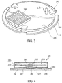
Figure 3 is an enlarged view of the break-away structure ofFigure 2 . -
Figure 4 is a cross-sectional view of the RFID transponder ofFigure 2 . - Various examples of the disclosure will now be described. The following description provides specific details for a thorough understanding and enabling description of these examples. One skilled in the art will understand, however, that the disclosure may be practiced without many of these details. Additionally, some well-known structures or functions may not be shown or described in detail, so as to avoid unnecessarily obscuring the relevant description.
- The terminology used in the description presented below is intended to be interpreted in its broadest reasonable manner, even though it is being used in conjunction with a detailed description of certain specific examples of the disclosure. Certain terms may even be emphasized below; however, any terminology intended to be interpreted in any restricted manner will be overtly and specifically defined as such in this Detailed Description section.
- Examples according to the disclosure may find ready applications in a setting where RFID tags are placed on vehicles. These applications may include, for example, paying tolls, parking, purchasing gas, and any other application. It should be understood that, while examples of the present disclosure are discussed herein with regard to a vehicle, the present disclosure may not be so limited and could be applied to various other applications.
-
Figure 1 illustrates an RFID system 100 including anRFID unit 104 and anRFID transponder 106. TheRFID unit 104 is configured to read from and/or write totransponders 106 within the range 112of theRFID unit 104. According to one embodiment, theRFID unit 104 includes atransceiver 114, a read/write module 116, aunique identifier 118 stored in memory, and an antenna. The RFIDtransponder 106includes memory 108 where a code associated with theRFID transponder 106 is stored. The code of the RFID transponder 106identifies the item it is attached thereto. For example, a transponder attached to a vehicle has a code that identifies the vehicle and other data associated with the vehicle, such as the registered owner, the license plate number, and/or any other information about the vehicle. The transponder code is capable of being modified to add or change the data therein. In one embodiment, a unique identifier may be added as a prefix to the code of the transponder by theRFID unit 104. In another embodiment, the unique identifier does not modify the code but instead is saved as an additional code in the transponder. Regardless, when anRFID unit 104 queries theRFID transponder 106, theRFID transponder 106 may transmit back to theRFID unit 104 both the code and the unique identifier. - The antenna of the
RFID unit 104 is designed to transmit a signal to a transponder which instructs the transponder to write the unique identifier to the transponder, such as a prefix to the previously-stored code. The transponders may be "passive" RFID tags, "active" RFID tags, or "battery assisted passive" (BAP) tags. Passive RFID tags are a type of transponder that does not contain their own power source or transmitter. When radio waves from the RFID writer reach the transponder's antenna, the energy is converted by the transponder's antenna into electricity that can power up the microcontroller in the tag (typically via inductive coupling). The passive RIFD tag is then able to receive and store the unique identifier to memory at the RFID tag by modulating the RFID reader's electromagnetic waves. "Active" RFID tags have their own power source and transmitter. The power source, usually a battery, is used to run the microcontroller's circuitry and to broadcast a signal to an RFID reader. Passive RFID tags do not have as great a range as active RFID tags, but it should be understood that either type of transponder may be employed in the present application. - When the
RFID transponder 106 is within therange 112 of theRFID unit 104, theRFID unit 104 may receive a code stored in thememory 108 associated with theRFID transponder 106 is stored. It should be understood that theRFID unit 104 may be a RFID reader/writer that is configured to read from and write to transponders. - Referring now to
Figure 2 , theRFID transponder 106 may be, for example, a BAP RFID transponder. Thetransponder 106 may include a housing 230 (Figure 4 ) having atop portion 232 and abottom portion 234. According to various aspects, the top andbottom portions housing 230 can be constructed of rigid, non-flexible parts that create an enclosure around the RFID transponder. For example, thehousing 230 can be constructed from plastics or fiberglass materials, but can also be constructed of any material suitable for encapsulating resonant components at ultra-high frequencies. - The
housing 230 contains a printedcircuit board 236. The printedcircuit board 236 may be a substrate, which for example is rigid or flexible and on which amicrocontroller 237, a battery, and an antenna are constructed. In some aspects, the printedcircuit board 236 can be replaced with a PET plastic film with an adhered conductive metal layer. It should be understood that the substrate may include amicrocontroller 237, which has both an analogue part for modifying the impedance matching of an antenna circuitry and a digital part for holding the logical functions and memory which enable RFID functionalities according to the air-interface standards that are used in theRFID transponder 106. The substrate may also include a battery, for example, a 3 volt battery, attached to themicrocontroller 237 by means of conductive path, such as a conductive wire between the battery and themicrocontroller 237, conductive glue, or mechanical bond between themicrocontroller 237 and the battery. The battery may be, for example, a thin-film battery with thickness less to 1 millimeter. The printed circuit board 236may include an antenna arranged to receive/backscatter radio frequency interrogation radiation from/to theRFID unit 104. - As shown in
Figure 2 , the printedcircuit board 236 includes a capacitive member, or capacitor, 238 implemented on the printedcircuit board 236. Themicrocontroller 237 is programmed to periodically probe thecapacitor 238 to measure the capacitance and determine whether the capacitance of thecapacitor 238 has changed. If themicrocontroller 237 determines that thecapacitor 238 experiences a change of capacitance that exceeds a predetermined threshold, themicrocontroller 237 disables thetransponder 106. - The
transponder 106 includes a break-away structure 240 couplable with thebottom portion 234 of thehousing 230. For example, as shown inFigure 3 , the break-away structure 240 may have a raisedcenter region 242 and aperipheral flange 244. The raisedcenter portion 242 is sized and arranged to be received by thecutout region 250 of thebottom portion 234 of thehousing 230. Thecenter portion 242 may include a plurality oftabs 243 spaced about its periphery. Thetabs 243 may extend outward of the periphery of thecenter portion 242 - When the top and
bottom portions housing 230 are assembled to contain the printedcircuit board 236, the raisedcentered portion 242 of the break-away structure 240 slightly enters thecutout region 250 such that thetabs 243 extending from the surface of thecutout region 250 can engage aninner surface 245 of thebottom portion 234 of thehousing 230 thus removably coupling the break-away structure 240 to thehousing 230. When the break-away structure 240 is coupled with thehousing 230, asurface 246 of the raisedcenter portion 242 faces the printedcircuit board 236 within thehousing 230, while theperipheral flange 244 remains outside thebottom portion 232 of thehousing 230. As illustrated inFigure 3 , thesurface 246 of the raisedcenter portion 242 includes a raisedplatform 248. - Referring again to
Figure 2 , thetransponder 106 includes a firstconductive foam member 252 and a secondconductive foam member 254. As illustrated inFigure 4 , when the break-away structure 240 is coupled with thebottom portion 234 of thehousing 230, the firstconductive foam member 252 is positioned between thetop portion 232 of thehousing 230 and thecapacitor 238 on afirst side 233 of the printedcircuit board 236 facing thetop portion 232 of thehousing 230. The secondconductive foam member 254 is positioned between the raisedplatform 248 and thecapacitor 238 on asecond side 235 of the printedcircuit board 236 facing thebottom portion 234 of thehousing 230. - As discussed above, the
capacitor 238 is electrically incorporated into the printedcircuit board 236 such that themicrocontroller 237 can enable and disable the printedcircuit board 236, and thus thetransponder 106, depending on the capacitance of thecapacitor 238. For example, when the first and secondconductive foam members capacitor 238 on the first and second sides of the printedcircuit board 236, the capacitance of thecapacitor 238 remains substantially unchanged. Themicrocontroller 237 thus determines that thecapacitor 238 has not experienced a capacitance change that exceeds the predetermined threshold. As a result, the printedcircuit board 236 is enabled and thetransponder 106 is operable. However, when either one or both of the first and secondconductive foam members capacitor 238 on the first and/or second side of the printedcircuit board 236, the capacitance of thecapacitor 238 changes. If themicrocontroller 237 then determines that thecapacitor 238 has experienced a capacitance change that exceeds the predetermined threshold, themicrocontroller 237 disables the printedcircuit board 236 and thetransponder 106 is inoperable. It should be understood that the printedcircuit board 236 may be "scrambled" when either one or both of the first and secondconductive foam members capacitor 238 such that a capacitance change exceeds the predetermined threshold. The printedcircuit board 236 may remain scrambled until it is reprogrammed. Thus, even if both the first and secondconductive foam members circuit board 236 is not re-enabled and thetransponder 106 remains inoperable. In one embodiment, to disable the transponder, power may be removed from the transponder or one or more other components from the transponder may be disconnected. In this regard, the transponder would effectively be disabled. - The
RFID transponder 106 includes anadhesive member 260 for coupling thetransponder 106 to anattachment surface 290. Theattachment surface 290 may be, for example, a windshield, dashboard, or other surface of a vehicle. In some aspects, theadhesive member 260 may be a double-sided tape such as, for example, very high bond (VHB) or ultra high bond (UHB) double-sided tape. The bonding strength of theadhesive member 260 should be selected to provide a substantially permanent connection between thetransponder 106 and theattachment surface 290. As shown inFigures 1 and4 , theadhesive member 260 may be sized and arranged to couple the break-away structure 240 of the transponder with theattachment surface 290. The bonding strength of theadhesive member 260 should be sufficient to keep the break-away structure 240 coupled with theattachment surface 290 even when a force is applied to thehousing 230 of the transponder that causes thebottom portion 234 of thehousing 230 to become decoupled from the break-away structure 240. Thus, if a force is applied to thetransponder 106 in an attempt to remove thetransponder 106 from theattachment surface 290, the force will cause thebottom portion 234 of thehousing 230 to become decoupled from the break-away structure 240 while theadhesive member 260 will maintain attachment between the break-away structure 240 and theattachment surface 290. When thebottom portion 234 of thehousing 230 is decoupled from the break-away structure 240, the secondconductive foam member 254 moves away from thecapacitor 238 on the second side of the printedcircuit board 236 that faces thebottom portion 234 of thehousing 230. The movement of the secondconductive foam member 254 away from thecapacitor 238 on the second side of the printedcircuit board 236 will result in a capacitance change that exceeds the predetermined threshold, and the printedcircuit board 236 is disabled and thetransponder 106 is inoperable. The printedcircuit board 236 may also be "scrambled" when the capacitance change exceeds the predetermined threshold. The printedcircuit board 236 may remain scrambled until it is reprogrammed. - In some aspects, the break-
away structure 240 may be configured as a circular shape, and the secondconductive foam member 254 may be positioned off-center on the break-away structure 240 such that the break-away structure 240 must be correctly rotationally aligned relative to the printedcircuit board 236 in order to sandwich the secondconductive foam member 254 between the raisedplatform 248 and thecapacitor 238 on the second side of the printedcircuit board 236 facing thebottom portion 234 of thehousing 230. This break-away structure 240 and thebottom portion 234 of thehousing 230 may be provided with alignment markers, as would be understood by persons skilled in the art, in order to ensure proper alignment. The rotational alignment provides another mechanism for preventing tampering with thetransponder 106. For example, ifhousing 230 is rotated relative to the break-away structure 240, which is fixedly attached to theattachment surface 290, the secondconductive foam member 254 may be moved a distance away from thecapacitor 238 on the second side of the printedcircuit board 236 causing a capacitance change that exceeds the predetermined threshold, and the printedcircuit board 236 is disabled and thetransponder 106 is inoperable. The printedcircuit board 236 may also be "scrambled" when the capacitance change exceeds the predetermined threshold. The printedcircuit board 236 may remain scrambled until it is reprogrammed. - According to some aspects, the break-away structure 24 may include a
tamper tab 270. When the top andbottom portions housing 230 are assembled, thetamper tab 270 extends through theopening 250 in thebottom portion 234 and cooperates with a corresponding throughhole 272 in the printedcircuit board 236. Thus, if someone tries to twist thetransponder 106 in an attempt to remove thetransponder 106 from theattachment surface 290, thetamper tab 270 breaks and the top andbottom portions housing 230 separate. As a result, one or both of theconductive foam members capacitor 238, thereby creating a capacitive change that exceeds the predetermined threshold. The printedcircuit board 236 is then disabled and thetransponder 106 is inoperable. The printedcircuit board 236 may also be "scrambled" when the capacitance change exceeds the predetermined threshold. The printedcircuit board 236 may remain scrambled until it is reprogrammed. - Unless the context clearly requires otherwise, throughout the description and the claims, the words "comprise," "comprising," and the like are to be construed in an inclusive sense, as opposed to an exclusive or exhaustive sense; that is to say, in the sense of "including, but not limited to." As used herein, the terms "connected," "coupled," or any variant thereof, means any connection or coupling, either direct or indirect, between two or more elements; the coupling of connection between the elements can be physical, logical, or a combination thereof. Additionally, the words "herein," "above," "below," and words of similar import, when used in this application, shall refer to this application as a whole and not to any particular portions of this application. Where the context permits, words in the above Detailed Description using the singular or plural number may also include the plural or singular number respectively. The word "or," in reference to a list of two or more items, covers all of the following interpretations of the word: any of the items in the list, all of the items in the list, and any combination of the items in the list.
- The above detailed description of embodiments of the disclosure is not intended to be exhaustive or to limit the disclosure to the precise form disclosed above. While specific embodiments of, and examples for, the disclosure are described above for illustrative purposes, various equivalent modifications are possible within the scope of the disclosure, as those skilled in the relevant art will recognize. For example, while processes or blocks are presented in a given order, alternative embodiments may perform routines having steps, or employ systems having blocks, in a different order, and some processes or blocks may be deleted, moved, added, subdivided, combined, and/or modified to provide alternative or subcombinations. Each of these processes or blocks may be implemented in a variety of different ways. Also, while processes or blocks are at times shown as being performed in series, these processes or blocks may instead be performed in parallel, or may be performed at different times. Further any specific numbers noted herein are only examples: alternative implementations may employ differing values or ranges.
- The teachings of the disclosure provided herein can be applied to other systems, not necessarily the system described above. The elements and acts of the various embodiments described above can be combined to provide further embodiments.
- Any patents and applications and other references noted above, including any that may be listed in accompanying filing papers, are incorporated herein by reference. Aspects of the disclosure can be modified, if necessary, to employ the systems, functions, and concepts of the various references described above to provide yet further embodiments of the disclosure.
- These and other changes can be made to the disclosure in light of the above Detailed Description. While the above description describes certain embodiments of the disclosure, and describes the best mode contemplated, no matter how detailed the above appears in text, the disclosure can be practiced in many ways. Details of the system may vary considerably in its implementation details, while still being encompassed by the disclosure disclosed herein. As noted above, particular terminology used when describing certain features or aspects of the disclosure should not be taken to imply that the terminology is being redefined herein to be restricted to any specific characteristics, features, or aspects of the disclosure with which that terminology is associated. In general, the terms used in the following claims should not be construed to limit the disclosure to the specific embodiments disclosed in the specification, unless the above Detailed Description section explicitly defines such terms. Accordingly, the actual scope of the disclosure encompasses not only the disclosed embodiments, but also all equivalent ways of practicing or implementing the disclosure under the claims.
- While certain aspects of the disclosure are presented below in certain claim forms, the inventors contemplate the various aspects of the disclosure in any number of claim forms. Accordingly, the inventors reserve the right to add additional claims after filing the application to pursue such additional claim forms for other aspects of the disclosure.
- Preferred numbered features of the invention are as follows:
- 1. A radio frequency identification (RFID) transponder, comprising:
- a substrate disposed with a housing;
- a capacitor coupled with the substrate;
- an antenna being arranged to receive a radio frequency interrogation signal;
- a structure configured to be detachably coupled with the housing; and
- a conductor positioned between the structure and the capacitor;
- wherein an adhesive member is configured to be coupled between the structure and an attachment surface of an object, and
- wherein, in response to the structure being decoupled from the housing, the adhesive member causes the conductor to separate from the capacitor, which disables the transponder.
- 2. The RFID transponder of feature 1, wherein a capacitance is measured when the conductor separates from the capacitor.
- 3. The RFID transponder of feature 2, wherein the capacitance change is determined whether or not it exceeds a predetermined threshold.
- 4. The RFID transponder of feature 3, wherein the transponder is disabled when the capacitance change is determined to have exceeded the predetermined threshold.
- 5. The RFID transponder of feature 1, wherein to disable the transponder, a controller of the RFID transponder is scrambled so that the transponder is scrambled until the controller is reprogrammed.
- 6. The RFID transponder of feature 1, wherein, to disable the transponder, the transponder is disconnected from a power source.
- 7. The RFID transponder of feature 1, wherein an attachment strength of the adhesive member between the structure and the attachment surface is greater than a force required to decouple the structure from the housing.
- 8. The RFID transponder of feature 1, further comprising a microcontroller that detects when the conductor separates from the capacitor and, in response to detecting the conductor moving away from the capacitor, disables the RFID transponder.
- 9. The RFID transponder of feature 7, wherein the microcontroller is disposed on the substrate and wherein the antenna is disposed on the substrate.
- 10. The RFID transponder of feature 1, wherein the conductor comprises a conductive foam structure.
- 11. The RFID transponder of feature 1, wherein the capacitor is coupled to a side surface of the substrate.
- 12. A method of radio frequency identification (RFID) communications, the method comprising:
- Providing a transponder comprising: a substrate, an antenna, and a structure, wherein a first side surface of the substrate includes a capacitor,
- detachably coupling the device with the substrate via a conductive member positioned between the structure and the capacitor of the substrate, the structure being attached to an attachment surface so that an attachment strength between the structure and the attachment surface is greater than a force required to decouple the structure from the substrate; and
- decoupling the structure from the substrate so that the conductive foam member separates from the capacitor, thereby disabling the transponder.
- 13. The method of feature 11, further comprising measuring a capacitance change when the conductive foam member separates from the capacitor.
- 14. The method of feature 12, further comprising:
- determining whether the capacitance change exceeds a predetermined threshold, and
- disabling the transponder when the capacitance change exceeds a predetermined threshold.
- 15. The method of feature 11, further comprising scrambling a controller of the RFID transponder when the transponder is disabled, thereby disabling the transponder until the controller is reprogrammed.
Claims (13)
- A radio frequency identification, RFID, transponder (106), comprising:a substrate (236) disposed with a housing (230);a capacitor (238) coupled with the substrate;an antenna arranged on the substrate to receive a radio frequency interrogation signal;a structure (240) configured to be coupled with the housing;characterized by:a conductor (252, 254) positioned between the structure and the capacitor;wherein the structure (240) is configured to be secured to an attachment surface (290), preferably by an adhesive member (260);wherein the capacitor (238) is periodically probed to measure a capacitance of the capacitor;wherein, in response to the structure (240) being moved relative to the housing (230), the conductor moves away from the capacitor resulting in a capacitance change,wherein the transponder (106) is disabled when the capacitance change exceeds a predetermined threshold.
- The radio frequency identification, RFID, transponder (106) of Claim 1 wherein:structure (240) is detachably coupled with the housing and configured such that, in response to the structure being decoupled from the housing, the conductor moves away from the capacitor resulting in the capacitance change.
- The radio frequency identification, RFID, transponder (106) of Claim 1 or claim 2 configured such that:the bonding strength of the adhesive member (260) is sufficient to keep the break-away structure (240) coupled with the attachment surface (290), when so coupled, even when a force is applied to the housing (230) of the transponder that causes the bottom portion (234) of the housing (232) become decoupled from the break-away structure (240).
- The radio frequency identification, RFID, transponder (106) of Claim 2 configured such that:when a bottom portion (234) of the housing (230) is decoupled from the break-away structure (240), a second conductive foam member (254) moves away from the capacitor (238) on a second side of the printed circuit board (236) that faces a bottom portion (234) of the housing (230).
- The radio frequency identification, RFID, transponder (106) of Claim 4 further configured such that:the movement of the second conductive foam member (254) away from the capacitor (238) on the second side of the printed circuit board (236) results in a capacitance change that when exceeding a predetermined threshold, the printed circuit board 236 is configured to be disabled and the transponder 106 made inoperable.
- The radio frequency identification, RFID, transponder (106) of any preceding claim wherein:the attachment surface (290) is a windshield, dashboard or other surface of a vehicle.
- The radio frequency identification, RFID, transponder (106) of any preceding claim wherein:the adhesive member is double sided tape.
- The radio frequency identification, RFID, transponder (106) of Claim 1 and configured such that on the housing (230) being rotated relative to the structure (240) the conductor separates from the capacitor resulting in the capacitance change.
- The radio frequency identification, RFID, transponder (106) of Claims 1, 2 or claim 8 wherein:the break-away structure 240 is configured as a circular shape, and a conductive foam member (254) is be positioned off-center on the break-away structure (240) such that the break-away structure 240 must be correctly rotationally aligned relative to the printed circuit board 236 in order to sandwich the conductive foam member (254) between a raised platform (248) and the capacitor (238) on a second side of the printed circuit board (236) facing the bottom portion (234) of the housing (230).
- The radio frequency identification, RFID, transponder (106) of claim 8 wherein:the break-away structure 240 and the bottom portion 234 of the housing 230 are provided with alignment markers, to ensure alignment.
- The radio frequency identification, RFID, transponder (106) of claim 9 configured such that:if housing (230) is rotated relative to the break-away structure (240), when fixedly attached to an attachment surface 290, the conductive foam member (254) is moved a distance away from the capacitor 238 on the second side of the printed circuit board 236 causing a capacitance change that exceeds the predetermined threshold, and the printed circuit board 236 is disabled and the transponder 106 made inoperable.
- The radio frequency identification, RFID, transponder (106) of claims 8 to 11 wherein:the attachment surface (290) is a windshield, dashboard or other surface of a vehicle.
- The radio frequency identification, RFID, transponder (106) of claims 8 to 12 wherein:the adhesive member is double sided tape.
Applications Claiming Priority (3)
| Application Number | Priority Date | Filing Date | Title |
|---|---|---|---|
| US201462099104P | 2014-12-31 | 2014-12-31 | |
| US14/956,763 US9542637B2 (en) | 2014-12-31 | 2015-12-02 | RFID tag with anti-tamper assembly |
| EP15200979.1A EP3040913B1 (en) | 2014-12-31 | 2015-12-17 | Rfid tag with anti-tamper assembly |
Related Parent Applications (1)
| Application Number | Title | Priority Date | Filing Date |
|---|---|---|---|
| EP15200979.1A Division EP3040913B1 (en) | 2014-12-31 | 2015-12-17 | Rfid tag with anti-tamper assembly |
Publications (2)
| Publication Number | Publication Date |
|---|---|
| EP3217327A1 true EP3217327A1 (en) | 2017-09-13 |
| EP3217327B1 EP3217327B1 (en) | 2021-11-17 |
Family
ID=54936871
Family Applications (2)
| Application Number | Title | Priority Date | Filing Date |
|---|---|---|---|
| EP17165490.8A Active EP3217327B1 (en) | 2014-12-31 | 2015-12-17 | Rfid tag with anti-tamper assembly |
| EP15200979.1A Active EP3040913B1 (en) | 2014-12-31 | 2015-12-17 | Rfid tag with anti-tamper assembly |
Family Applications After (1)
| Application Number | Title | Priority Date | Filing Date |
|---|---|---|---|
| EP15200979.1A Active EP3040913B1 (en) | 2014-12-31 | 2015-12-17 | Rfid tag with anti-tamper assembly |
Country Status (4)
| Country | Link |
|---|---|
| US (3) | US9542637B2 (en) |
| EP (2) | EP3217327B1 (en) |
| CN (1) | CN105868664B (en) |
| BR (1) | BR102015032862B1 (en) |
Families Citing this family (11)
| Publication number | Priority date | Publication date | Assignee | Title |
|---|---|---|---|---|
| US12327293B2 (en) * | 2013-03-13 | 2025-06-10 | Promega Corporation | Radio frequency identification system |
| CN106845611A (en) * | 2017-01-20 | 2017-06-13 | 北京华海隆科技有限公司 | A kind of wireless programmable electronic tag |
| EP3397008A1 (en) * | 2017-04-25 | 2018-10-31 | Siemens Aktiengesellschaft | Method and assembly for starting up an initial device which is battery powered and at least partially protected against mechanical access designed to function on the basis of near field communication, in particular nfc |
| US10628723B2 (en) | 2018-07-10 | 2020-04-21 | Datamax-O'neil Corporation | Methods, systems, and apparatuses for encoding a radio frequency identification (RFID) inlay |
| FI3597274T3 (en) | 2018-07-16 | 2023-03-25 | Marioff Corp Oy | Sprinkler system including a sprinkler and an identification device |
| EP3621047B1 (en) | 2018-09-06 | 2021-04-28 | Nxp B.V. | System and method for detecting tampering with a product |
| WO2020069541A1 (en) | 2018-10-04 | 2020-04-09 | Riddle & Code Gmbh | Electronic marking |
| DK3702003T3 (en) | 2019-03-01 | 2021-06-21 | Marioff Corp Oy | SPRINKLE NOZZLE WITH A FLASH WITH A RELEASED RFID CIRCUIT |
| UA130525C2 (en) | 2020-03-20 | 2026-03-11 | Гуала Клоужес С.П.А. | Closure element |
| US12493769B2 (en) * | 2022-05-10 | 2025-12-09 | Assa Abloy Ab | RFID tag for a tamper proof attachment to an object such as a licence plate |
| CN118396022A (en) * | 2024-06-11 | 2024-07-26 | 北京海阳博创科技股份有限公司 | Dose storage device and method for radiation dose measurement and capable of preventing information tampering |
Citations (3)
| Publication number | Priority date | Publication date | Assignee | Title |
|---|---|---|---|---|
| EP1132859A2 (en) * | 2000-03-09 | 2001-09-12 | Sony Chemicals Corporation | Information recording security tag |
| US20040104274A1 (en) * | 2002-03-18 | 2004-06-03 | Kotik Mark M. | Identification band with adhesively attached coupling elements |
| US20070125867A1 (en) * | 2005-12-05 | 2007-06-07 | Rcd Technology Corp. | Tuned radio frequency identification (RFID) circuit used as a security device for wristbands and package security |
Family Cites Families (12)
| Publication number | Priority date | Publication date | Assignee | Title |
|---|---|---|---|---|
| DE3475499D1 (en) | 1983-07-26 | 1989-01-12 | De La Rue Giori Sa | Perfecting rotary multicolour printing machine |
| US7012504B2 (en) * | 2002-04-01 | 2006-03-14 | Micron Technology, Inc. | Wireless identification device, RFID device with push-on/push off switch, and method of manufacturing wireless identification device |
| US7095324B2 (en) * | 2001-03-06 | 2006-08-22 | Intermec Ip Corp | Tamper evident smart label with RF transponder |
| DE10310135A1 (en) * | 2003-03-07 | 2004-09-16 | Checkpoint Systems International Gmbh | Security label and method for securing objects |
| DE102004013175A1 (en) * | 2004-03-17 | 2005-10-06 | Atmel Germany Gmbh | Circuit arrangement for load regulation in the receive path of a transponder |
| US7151455B2 (en) * | 2004-04-30 | 2006-12-19 | Kimberly-Clark Worldwide, Inc. | Activating a data tag by load or orientation or user control |
| DE102005036303A1 (en) * | 2005-04-29 | 2007-08-16 | Giesecke & Devrient Gmbh | Method for initializing and / or personalizing a portable data carrier |
| SE528760C2 (en) * | 2005-05-18 | 2007-02-13 | Secure Logistics Sweden Ab | Method and apparatus for detecting intrusion into or manipulation of the contents of an enclosure |
| WO2007013357A1 (en) * | 2005-07-29 | 2007-02-01 | Kabushiki Kaisha Sato | Rfid label attaching method, rfid label attaching device, and rfid label |
| US20110285507A1 (en) * | 2010-05-21 | 2011-11-24 | Nelson Erik T | Tamper Detection RFID Tape |
| WO2012145715A2 (en) * | 2011-04-22 | 2012-10-26 | Expanergy,Llc. | Systems and methods for analyzing energy usage |
| US8378710B1 (en) * | 2011-09-20 | 2013-02-19 | Nxp B.V. | Secure device anti-tampering circuit |
-
2015
- 2015-12-02 US US14/956,763 patent/US9542637B2/en active Active
- 2015-12-17 EP EP17165490.8A patent/EP3217327B1/en active Active
- 2015-12-17 EP EP15200979.1A patent/EP3040913B1/en active Active
- 2015-12-29 BR BR102015032862-1A patent/BR102015032862B1/en active IP Right Grant
- 2015-12-31 CN CN201511013943.9A patent/CN105868664B/en active Active
-
2017
- 2017-01-06 US US15/400,338 patent/US10062026B2/en active Active
-
2018
- 2018-08-14 US US16/103,073 patent/US10565488B2/en active Active
Patent Citations (3)
| Publication number | Priority date | Publication date | Assignee | Title |
|---|---|---|---|---|
| EP1132859A2 (en) * | 2000-03-09 | 2001-09-12 | Sony Chemicals Corporation | Information recording security tag |
| US20040104274A1 (en) * | 2002-03-18 | 2004-06-03 | Kotik Mark M. | Identification band with adhesively attached coupling elements |
| US20070125867A1 (en) * | 2005-12-05 | 2007-06-07 | Rcd Technology Corp. | Tuned radio frequency identification (RFID) circuit used as a security device for wristbands and package security |
Also Published As
| Publication number | Publication date |
|---|---|
| US10565488B2 (en) | 2020-02-18 |
| CN105868664A (en) | 2016-08-17 |
| US10062026B2 (en) | 2018-08-28 |
| US20160189022A1 (en) | 2016-06-30 |
| EP3040913B1 (en) | 2017-04-12 |
| BR102015032862B1 (en) | 2022-09-20 |
| US20170116506A1 (en) | 2017-04-27 |
| US20190005370A1 (en) | 2019-01-03 |
| US9542637B2 (en) | 2017-01-10 |
| BR102015032862A2 (en) | 2017-08-08 |
| CN105868664B (en) | 2020-07-21 |
| EP3040913A1 (en) | 2016-07-06 |
| EP3217327B1 (en) | 2021-11-17 |
Similar Documents
| Publication | Publication Date | Title |
|---|---|---|
| US10565488B2 (en) | RFID tag with anti-tamper assembly | |
| US12518125B2 (en) | Systems and methods for a RFID enabled metal license plate | |
| EP2250631B1 (en) | Methods and apparatus for preserving privacy in an rfid system | |
| RU2313829C2 (en) | Product with light reflection property which is sensitive to radio frequencies | |
| ES2317187T3 (en) | FIELD CONFORMATION SHIELD FOR A RADIO FREQUENCY IDENTIFICATION SYSTEM (RFID). | |
| WO2008079556A2 (en) | A tamper-indicating radio frequency identification tag and methods of indicating tampering of a radio frequency identification tag | |
| JP5026522B2 (en) | Optimized reading method and system for transponders for high frequency communications using passive resonant circuits | |
| WO2007133690A2 (en) | Radio frequency identification (rfid) tag antenna design | |
| WO2004027689A2 (en) | A data input device | |
| RS65444B1 (en) | VEHICLE IDENTIFICATION MEANS | |
| US8665093B2 (en) | Anti theft electronic apparatus | |
| US20080062046A1 (en) | Mounting structure for matching an rf integrated circuit with an antenna and rfid device implementing same | |
| Hagl et al. | RFID: Fundamentals and applications |
Legal Events
| Date | Code | Title | Description |
|---|---|---|---|
| PUAI | Public reference made under article 153(3) epc to a published international application that has entered the european phase |
Free format text: ORIGINAL CODE: 0009012 |
|
| STAA | Information on the status of an ep patent application or granted ep patent |
Free format text: STATUS: REQUEST FOR EXAMINATION WAS MADE |
|
| 17P | Request for examination filed |
Effective date: 20170407 |
|
| AC | Divisional application: reference to earlier application |
Ref document number: 3040913 Country of ref document: EP Kind code of ref document: P |
|
| AK | Designated contracting states |
Kind code of ref document: A1 Designated state(s): AL AT BE BG CH CY CZ DE DK EE ES FI FR GB GR HR HU IE IS IT LI LT LU LV MC MK MT NL NO PL PT RO RS SE SI SK SM TR |
|
| REG | Reference to a national code |
Ref country code: DE Ref legal event code: R079 Ref document number: 602015075165 Country of ref document: DE Free format text: PREVIOUS MAIN CLASS: G06K0019073000 Ipc: H04W0004800000 |
|
| GRAP | Despatch of communication of intention to grant a patent |
Free format text: ORIGINAL CODE: EPIDOSNIGR1 |
|
| STAA | Information on the status of an ep patent application or granted ep patent |
Free format text: STATUS: GRANT OF PATENT IS INTENDED |
|
| RIC1 | Information provided on ipc code assigned before grant |
Ipc: H04W 4/80 20180101AFI20200730BHEP Ipc: G06K 19/073 20060101ALI20200730BHEP |
|
| INTG | Intention to grant announced |
Effective date: 20200817 |
|
| GRAJ | Information related to disapproval of communication of intention to grant by the applicant or resumption of examination proceedings by the epo deleted |
Free format text: ORIGINAL CODE: EPIDOSDIGR1 |
|
| STAA | Information on the status of an ep patent application or granted ep patent |
Free format text: STATUS: REQUEST FOR EXAMINATION WAS MADE |
|
| INTC | Intention to grant announced (deleted) | ||
| GRAP | Despatch of communication of intention to grant a patent |
Free format text: ORIGINAL CODE: EPIDOSNIGR1 |
|
| STAA | Information on the status of an ep patent application or granted ep patent |
Free format text: STATUS: GRANT OF PATENT IS INTENDED |
|
| INTG | Intention to grant announced |
Effective date: 20210129 |
|
| GRAJ | Information related to disapproval of communication of intention to grant by the applicant or resumption of examination proceedings by the epo deleted |
Free format text: ORIGINAL CODE: EPIDOSDIGR1 |
|
| STAA | Information on the status of an ep patent application or granted ep patent |
Free format text: STATUS: REQUEST FOR EXAMINATION WAS MADE |
|
| INTC | Intention to grant announced (deleted) | ||
| GRAS | Grant fee paid |
Free format text: ORIGINAL CODE: EPIDOSNIGR3 |
|
| STAA | Information on the status of an ep patent application or granted ep patent |
Free format text: STATUS: GRANT OF PATENT IS INTENDED |
|
| GRAP | Despatch of communication of intention to grant a patent |
Free format text: ORIGINAL CODE: EPIDOSNIGR1 |
|
| INTG | Intention to grant announced |
Effective date: 20210629 |
|
| GRAA | (expected) grant |
Free format text: ORIGINAL CODE: 0009210 |
|
| STAA | Information on the status of an ep patent application or granted ep patent |
Free format text: STATUS: THE PATENT HAS BEEN GRANTED |
|
| AC | Divisional application: reference to earlier application |
Ref document number: 3040913 Country of ref document: EP Kind code of ref document: P |
|
| AK | Designated contracting states |
Kind code of ref document: B1 Designated state(s): AL AT BE BG CH CY CZ DE DK EE ES FI FR GB GR HR HU IE IS IT LI LT LU LV MC MK MT NL NO PL PT RO RS SE SI SK SM TR |
|
| REG | Reference to a national code |
Ref country code: GB Ref legal event code: FG4D |
|
| REG | Reference to a national code |
Ref country code: IE Ref legal event code: FG4D |
|
| REG | Reference to a national code |
Ref country code: DE Ref legal event code: R096 Ref document number: 602015075165 Country of ref document: DE |
|
| REG | Reference to a national code |
Ref country code: AT Ref legal event code: REF Ref document number: 1449033 Country of ref document: AT Kind code of ref document: T Effective date: 20211215 |
|
| REG | Reference to a national code |
Ref country code: LT Ref legal event code: MG9D |
|
| REG | Reference to a national code |
Ref country code: NL Ref legal event code: MP Effective date: 20211117 |
|
| REG | Reference to a national code |
Ref country code: AT Ref legal event code: MK05 Ref document number: 1449033 Country of ref document: AT Kind code of ref document: T Effective date: 20211117 |
|
| PG25 | Lapsed in a contracting state [announced via postgrant information from national office to epo] |
Ref country code: RS Free format text: LAPSE BECAUSE OF FAILURE TO SUBMIT A TRANSLATION OF THE DESCRIPTION OR TO PAY THE FEE WITHIN THE PRESCRIBED TIME-LIMIT Effective date: 20211117 Ref country code: LT Free format text: LAPSE BECAUSE OF FAILURE TO SUBMIT A TRANSLATION OF THE DESCRIPTION OR TO PAY THE FEE WITHIN THE PRESCRIBED TIME-LIMIT Effective date: 20211117 Ref country code: FI Free format text: LAPSE BECAUSE OF FAILURE TO SUBMIT A TRANSLATION OF THE DESCRIPTION OR TO PAY THE FEE WITHIN THE PRESCRIBED TIME-LIMIT Effective date: 20211117 Ref country code: BG Free format text: LAPSE BECAUSE OF FAILURE TO SUBMIT A TRANSLATION OF THE DESCRIPTION OR TO PAY THE FEE WITHIN THE PRESCRIBED TIME-LIMIT Effective date: 20220217 Ref country code: AT Free format text: LAPSE BECAUSE OF FAILURE TO SUBMIT A TRANSLATION OF THE DESCRIPTION OR TO PAY THE FEE WITHIN THE PRESCRIBED TIME-LIMIT Effective date: 20211117 |
|
| PG25 | Lapsed in a contracting state [announced via postgrant information from national office to epo] |
Ref country code: IS Free format text: LAPSE BECAUSE OF FAILURE TO SUBMIT A TRANSLATION OF THE DESCRIPTION OR TO PAY THE FEE WITHIN THE PRESCRIBED TIME-LIMIT Effective date: 20220317 Ref country code: SE Free format text: LAPSE BECAUSE OF FAILURE TO SUBMIT A TRANSLATION OF THE DESCRIPTION OR TO PAY THE FEE WITHIN THE PRESCRIBED TIME-LIMIT Effective date: 20211117 Ref country code: PT Free format text: LAPSE BECAUSE OF FAILURE TO SUBMIT A TRANSLATION OF THE DESCRIPTION OR TO PAY THE FEE WITHIN THE PRESCRIBED TIME-LIMIT Effective date: 20220317 Ref country code: PL Free format text: LAPSE BECAUSE OF FAILURE TO SUBMIT A TRANSLATION OF THE DESCRIPTION OR TO PAY THE FEE WITHIN THE PRESCRIBED TIME-LIMIT Effective date: 20211117 Ref country code: NO Free format text: LAPSE BECAUSE OF FAILURE TO SUBMIT A TRANSLATION OF THE DESCRIPTION OR TO PAY THE FEE WITHIN THE PRESCRIBED TIME-LIMIT Effective date: 20220217 Ref country code: NL Free format text: LAPSE BECAUSE OF FAILURE TO SUBMIT A TRANSLATION OF THE DESCRIPTION OR TO PAY THE FEE WITHIN THE PRESCRIBED TIME-LIMIT Effective date: 20211117 Ref country code: LV Free format text: LAPSE BECAUSE OF FAILURE TO SUBMIT A TRANSLATION OF THE DESCRIPTION OR TO PAY THE FEE WITHIN THE PRESCRIBED TIME-LIMIT Effective date: 20211117 Ref country code: HR Free format text: LAPSE BECAUSE OF FAILURE TO SUBMIT A TRANSLATION OF THE DESCRIPTION OR TO PAY THE FEE WITHIN THE PRESCRIBED TIME-LIMIT Effective date: 20211117 Ref country code: GR Free format text: LAPSE BECAUSE OF FAILURE TO SUBMIT A TRANSLATION OF THE DESCRIPTION OR TO PAY THE FEE WITHIN THE PRESCRIBED TIME-LIMIT Effective date: 20220218 Ref country code: ES Free format text: LAPSE BECAUSE OF FAILURE TO SUBMIT A TRANSLATION OF THE DESCRIPTION OR TO PAY THE FEE WITHIN THE PRESCRIBED TIME-LIMIT Effective date: 20211117 |
|
| PG25 | Lapsed in a contracting state [announced via postgrant information from national office to epo] |
Ref country code: SM Free format text: LAPSE BECAUSE OF FAILURE TO SUBMIT A TRANSLATION OF THE DESCRIPTION OR TO PAY THE FEE WITHIN THE PRESCRIBED TIME-LIMIT Effective date: 20211117 Ref country code: SK Free format text: LAPSE BECAUSE OF FAILURE TO SUBMIT A TRANSLATION OF THE DESCRIPTION OR TO PAY THE FEE WITHIN THE PRESCRIBED TIME-LIMIT Effective date: 20211117 Ref country code: RO Free format text: LAPSE BECAUSE OF FAILURE TO SUBMIT A TRANSLATION OF THE DESCRIPTION OR TO PAY THE FEE WITHIN THE PRESCRIBED TIME-LIMIT Effective date: 20211117 Ref country code: EE Free format text: LAPSE BECAUSE OF FAILURE TO SUBMIT A TRANSLATION OF THE DESCRIPTION OR TO PAY THE FEE WITHIN THE PRESCRIBED TIME-LIMIT Effective date: 20211117 Ref country code: DK Free format text: LAPSE BECAUSE OF FAILURE TO SUBMIT A TRANSLATION OF THE DESCRIPTION OR TO PAY THE FEE WITHIN THE PRESCRIBED TIME-LIMIT Effective date: 20211117 Ref country code: CZ Free format text: LAPSE BECAUSE OF FAILURE TO SUBMIT A TRANSLATION OF THE DESCRIPTION OR TO PAY THE FEE WITHIN THE PRESCRIBED TIME-LIMIT Effective date: 20211117 |
|
| REG | Reference to a national code |
Ref country code: CH Ref legal event code: PL |
|
| REG | Reference to a national code |
Ref country code: DE Ref legal event code: R097 Ref document number: 602015075165 Country of ref document: DE |
|
| PG25 | Lapsed in a contracting state [announced via postgrant information from national office to epo] |
Ref country code: MC Free format text: LAPSE BECAUSE OF FAILURE TO SUBMIT A TRANSLATION OF THE DESCRIPTION OR TO PAY THE FEE WITHIN THE PRESCRIBED TIME-LIMIT Effective date: 20211117 |
|
| PLBE | No opposition filed within time limit |
Free format text: ORIGINAL CODE: 0009261 |
|
| STAA | Information on the status of an ep patent application or granted ep patent |
Free format text: STATUS: NO OPPOSITION FILED WITHIN TIME LIMIT |
|
| REG | Reference to a national code |
Ref country code: BE Ref legal event code: MM Effective date: 20211231 |
|
| 26N | No opposition filed |
Effective date: 20220818 |
|
| PG25 | Lapsed in a contracting state [announced via postgrant information from national office to epo] |
Ref country code: LU Free format text: LAPSE BECAUSE OF NON-PAYMENT OF DUE FEES Effective date: 20211217 Ref country code: IE Free format text: LAPSE BECAUSE OF NON-PAYMENT OF DUE FEES Effective date: 20211217 Ref country code: AL Free format text: LAPSE BECAUSE OF FAILURE TO SUBMIT A TRANSLATION OF THE DESCRIPTION OR TO PAY THE FEE WITHIN THE PRESCRIBED TIME-LIMIT Effective date: 20211117 |
|
| PG25 | Lapsed in a contracting state [announced via postgrant information from national office to epo] |
Ref country code: SI Free format text: LAPSE BECAUSE OF FAILURE TO SUBMIT A TRANSLATION OF THE DESCRIPTION OR TO PAY THE FEE WITHIN THE PRESCRIBED TIME-LIMIT Effective date: 20211117 Ref country code: BE Free format text: LAPSE BECAUSE OF NON-PAYMENT OF DUE FEES Effective date: 20211231 |
|
| PG25 | Lapsed in a contracting state [announced via postgrant information from national office to epo] |
Ref country code: LI Free format text: LAPSE BECAUSE OF NON-PAYMENT OF DUE FEES Effective date: 20211231 Ref country code: CH Free format text: LAPSE BECAUSE OF NON-PAYMENT OF DUE FEES Effective date: 20211231 |
|
| PG25 | Lapsed in a contracting state [announced via postgrant information from national office to epo] |
Ref country code: IT Free format text: LAPSE BECAUSE OF FAILURE TO SUBMIT A TRANSLATION OF THE DESCRIPTION OR TO PAY THE FEE WITHIN THE PRESCRIBED TIME-LIMIT Effective date: 20211117 Ref country code: HU Free format text: LAPSE BECAUSE OF FAILURE TO SUBMIT A TRANSLATION OF THE DESCRIPTION OR TO PAY THE FEE WITHIN THE PRESCRIBED TIME-LIMIT; INVALID AB INITIO Effective date: 20151217 |
|
| PG25 | Lapsed in a contracting state [announced via postgrant information from national office to epo] |
Ref country code: CY Free format text: LAPSE BECAUSE OF FAILURE TO SUBMIT A TRANSLATION OF THE DESCRIPTION OR TO PAY THE FEE WITHIN THE PRESCRIBED TIME-LIMIT Effective date: 20211117 |
|
| PG25 | Lapsed in a contracting state [announced via postgrant information from national office to epo] |
Ref country code: MK Free format text: LAPSE BECAUSE OF FAILURE TO SUBMIT A TRANSLATION OF THE DESCRIPTION OR TO PAY THE FEE WITHIN THE PRESCRIBED TIME-LIMIT Effective date: 20211117 |
|
| PG25 | Lapsed in a contracting state [announced via postgrant information from national office to epo] |
Ref country code: TR Free format text: LAPSE BECAUSE OF FAILURE TO SUBMIT A TRANSLATION OF THE DESCRIPTION OR TO PAY THE FEE WITHIN THE PRESCRIBED TIME-LIMIT Effective date: 20211117 |
|
| PG25 | Lapsed in a contracting state [announced via postgrant information from national office to epo] |
Ref country code: MT Free format text: LAPSE BECAUSE OF FAILURE TO SUBMIT A TRANSLATION OF THE DESCRIPTION OR TO PAY THE FEE WITHIN THE PRESCRIBED TIME-LIMIT Effective date: 20211117 |
|
| PGFP | Annual fee paid to national office [announced via postgrant information from national office to epo] |
Ref country code: GB Payment date: 20251223 Year of fee payment: 11 |
|
| PGFP | Annual fee paid to national office [announced via postgrant information from national office to epo] |
Ref country code: FR Payment date: 20251223 Year of fee payment: 11 |
|
| PGFP | Annual fee paid to national office [announced via postgrant information from national office to epo] |
Ref country code: DE Payment date: 20251229 Year of fee payment: 11 |