EP3217124A1 - Ice production machine with electromechanical peripheral apparatus and automatic washing control electronic device - Google Patents
Ice production machine with electromechanical peripheral apparatus and automatic washing control electronic device Download PDFInfo
- Publication number
- EP3217124A1 EP3217124A1 EP16425020.1A EP16425020A EP3217124A1 EP 3217124 A1 EP3217124 A1 EP 3217124A1 EP 16425020 A EP16425020 A EP 16425020A EP 3217124 A1 EP3217124 A1 EP 3217124A1
- Authority
- EP
- European Patent Office
- Prior art keywords
- evaporator
- machine
- ice
- machine according
- programming device
- Prior art date
- Legal status (The legal status is an assumption and is not a legal conclusion. Google has not performed a legal analysis and makes no representation as to the accuracy of the status listed.)
- Granted
Links
- 238000005406 washing Methods 0.000 title claims abstract description 12
- 238000004519 manufacturing process Methods 0.000 title claims description 24
- 230000002093 peripheral effect Effects 0.000 title 1
- XLYOFNOQVPJJNP-UHFFFAOYSA-N water Substances O XLYOFNOQVPJJNP-UHFFFAOYSA-N 0.000 claims abstract description 29
- 238000005507 spraying Methods 0.000 claims abstract description 6
- 239000007788 liquid Substances 0.000 claims abstract 4
- 238000004140 cleaning Methods 0.000 claims description 13
- 238000010257 thawing Methods 0.000 claims description 7
- 239000007921 spray Substances 0.000 claims description 3
- 230000004913 activation Effects 0.000 claims description 2
- 238000000034 method Methods 0.000 claims description 2
- 239000000498 cooling water Substances 0.000 claims 1
- 230000009849 deactivation Effects 0.000 claims 1
- 230000015572 biosynthetic process Effects 0.000 abstract description 2
- 239000012530 fluid Substances 0.000 description 14
- 230000006870 function Effects 0.000 description 12
- 238000010586 diagram Methods 0.000 description 7
- 230000015654 memory Effects 0.000 description 7
- 238000004891 communication Methods 0.000 description 4
- 238000012423 maintenance Methods 0.000 description 4
- 230000005540 biological transmission Effects 0.000 description 3
- 239000003599 detergent Substances 0.000 description 3
- 238000003825 pressing Methods 0.000 description 3
- 238000005057 refrigeration Methods 0.000 description 3
- 238000012360 testing method Methods 0.000 description 3
- 235000008733 Citrus aurantifolia Nutrition 0.000 description 2
- 235000011941 Tilia x europaea Nutrition 0.000 description 2
- 244000052616 bacterial pathogen Species 0.000 description 2
- 238000001816 cooling Methods 0.000 description 2
- 238000013461 design Methods 0.000 description 2
- 239000000645 desinfectant Substances 0.000 description 2
- 230000005484 gravity Effects 0.000 description 2
- 230000001788 irregular Effects 0.000 description 2
- 239000004571 lime Substances 0.000 description 2
- 238000007726 management method Methods 0.000 description 2
- 230000000737 periodic effect Effects 0.000 description 2
- 238000011012 sanitization Methods 0.000 description 2
- 239000000126 substance Substances 0.000 description 2
- UJPMYEOUBPIPHQ-UHFFFAOYSA-N 1,1,1-trifluoroethane Chemical compound CC(F)(F)F UJPMYEOUBPIPHQ-UHFFFAOYSA-N 0.000 description 1
- ZAMOUSCENKQFHK-UHFFFAOYSA-N Chlorine atom Chemical compound [Cl] ZAMOUSCENKQFHK-UHFFFAOYSA-N 0.000 description 1
- 238000004458 analytical method Methods 0.000 description 1
- 235000013361 beverage Nutrition 0.000 description 1
- 230000004397 blinking Effects 0.000 description 1
- 229910052801 chlorine Inorganic materials 0.000 description 1
- 239000000460 chlorine Substances 0.000 description 1
- 230000001419 dependent effect Effects 0.000 description 1
- 230000001627 detrimental effect Effects 0.000 description 1
- 238000007599 discharging Methods 0.000 description 1
- 239000006185 dispersion Substances 0.000 description 1
- 238000005516 engineering process Methods 0.000 description 1
- 230000007613 environmental effect Effects 0.000 description 1
- 239000011521 glass Substances 0.000 description 1
- 239000012535 impurity Substances 0.000 description 1
- 238000011065 in-situ storage Methods 0.000 description 1
- 238000009776 industrial production Methods 0.000 description 1
- 230000007246 mechanism Effects 0.000 description 1
- 239000000203 mixture Substances 0.000 description 1
- 230000001717 pathogenic effect Effects 0.000 description 1
- GTLACDSXYULKMZ-UHFFFAOYSA-N pentafluoroethane Chemical compound FC(F)C(F)(F)F GTLACDSXYULKMZ-UHFFFAOYSA-N 0.000 description 1
- 230000011664 signaling Effects 0.000 description 1
- 239000000344 soap Substances 0.000 description 1
- 239000007787 solid Substances 0.000 description 1
- 238000003860 storage Methods 0.000 description 1
- 230000001960 triggered effect Effects 0.000 description 1
- 230000000007 visual effect Effects 0.000 description 1
- 238000010792 warming Methods 0.000 description 1
Images




Classifications
-
- F—MECHANICAL ENGINEERING; LIGHTING; HEATING; WEAPONS; BLASTING
- F25—REFRIGERATION OR COOLING; COMBINED HEATING AND REFRIGERATION SYSTEMS; HEAT PUMP SYSTEMS; MANUFACTURE OR STORAGE OF ICE; LIQUEFACTION SOLIDIFICATION OF GASES
- F25C—PRODUCING, WORKING OR HANDLING ICE
- F25C1/00—Producing ice
- F25C1/22—Construction of moulds; Filling devices for moulds
- F25C1/25—Filling devices for moulds
-
- F—MECHANICAL ENGINEERING; LIGHTING; HEATING; WEAPONS; BLASTING
- F25—REFRIGERATION OR COOLING; COMBINED HEATING AND REFRIGERATION SYSTEMS; HEAT PUMP SYSTEMS; MANUFACTURE OR STORAGE OF ICE; LIQUEFACTION SOLIDIFICATION OF GASES
- F25C—PRODUCING, WORKING OR HANDLING ICE
- F25C1/00—Producing ice
- F25C1/12—Producing ice by freezing water on cooled surfaces, e.g. to form slabs
-
- F—MECHANICAL ENGINEERING; LIGHTING; HEATING; WEAPONS; BLASTING
- F25—REFRIGERATION OR COOLING; COMBINED HEATING AND REFRIGERATION SYSTEMS; HEAT PUMP SYSTEMS; MANUFACTURE OR STORAGE OF ICE; LIQUEFACTION SOLIDIFICATION OF GASES
- F25C—PRODUCING, WORKING OR HANDLING ICE
- F25C1/00—Producing ice
- F25C1/04—Producing ice by using stationary moulds
-
- F—MECHANICAL ENGINEERING; LIGHTING; HEATING; WEAPONS; BLASTING
- F28—HEAT EXCHANGE IN GENERAL
- F28G—CLEANING OF INTERNAL OR EXTERNAL SURFACES OF HEAT-EXCHANGE OR HEAT-TRANSFER CONDUITS, e.g. WATER TUBES OR BOILERS
- F28G1/00—Non-rotary, e.g. reciprocated, appliances
- F28G1/16—Non-rotary, e.g. reciprocated, appliances using jets of fluid for removing debris
- F28G1/166—Non-rotary, e.g. reciprocated, appliances using jets of fluid for removing debris from external surfaces of heat exchange conduits
-
- F—MECHANICAL ENGINEERING; LIGHTING; HEATING; WEAPONS; BLASTING
- F28—HEAT EXCHANGE IN GENERAL
- F28G—CLEANING OF INTERNAL OR EXTERNAL SURFACES OF HEAT-EXCHANGE OR HEAT-TRANSFER CONDUITS, e.g. WATER TUBES OR BOILERS
- F28G15/00—Details
- F28G15/003—Control arrangements
-
- F—MECHANICAL ENGINEERING; LIGHTING; HEATING; WEAPONS; BLASTING
- F25—REFRIGERATION OR COOLING; COMBINED HEATING AND REFRIGERATION SYSTEMS; HEAT PUMP SYSTEMS; MANUFACTURE OR STORAGE OF ICE; LIQUEFACTION SOLIDIFICATION OF GASES
- F25C—PRODUCING, WORKING OR HANDLING ICE
- F25C2400/00—Auxiliary features or devices for producing, working or handling ice
- F25C2400/12—Means for sanitation
-
- F—MECHANICAL ENGINEERING; LIGHTING; HEATING; WEAPONS; BLASTING
- F25—REFRIGERATION OR COOLING; COMBINED HEATING AND REFRIGERATION SYSTEMS; HEAT PUMP SYSTEMS; MANUFACTURE OR STORAGE OF ICE; LIQUEFACTION SOLIDIFICATION OF GASES
- F25C—PRODUCING, WORKING OR HANDLING ICE
- F25C2400/00—Auxiliary features or devices for producing, working or handling ice
- F25C2400/14—Water supply
-
- F—MECHANICAL ENGINEERING; LIGHTING; HEATING; WEAPONS; BLASTING
- F25—REFRIGERATION OR COOLING; COMBINED HEATING AND REFRIGERATION SYSTEMS; HEAT PUMP SYSTEMS; MANUFACTURE OR STORAGE OF ICE; LIQUEFACTION SOLIDIFICATION OF GASES
- F25C—PRODUCING, WORKING OR HANDLING ICE
- F25C2600/00—Control issues
- F25C2600/04—Control means
-
- F—MECHANICAL ENGINEERING; LIGHTING; HEATING; WEAPONS; BLASTING
- F25—REFRIGERATION OR COOLING; COMBINED HEATING AND REFRIGERATION SYSTEMS; HEAT PUMP SYSTEMS; MANUFACTURE OR STORAGE OF ICE; LIQUEFACTION SOLIDIFICATION OF GASES
- F25C—PRODUCING, WORKING OR HANDLING ICE
- F25C2700/00—Sensing or detecting of parameters; Sensors therefor
Definitions
- the present invention relates, in a more general aspect thereof, to machines for ice production, wherein the term "ice” means mainly, but not only, so-called ice cubes, i.e. those pieces of ice, not necessarily exactly cubical in shape but suitable for being placed into glasses, jugs and other similar beverage containers.
- ice means mainly, but not only, so-called ice cubes, i.e. those pieces of ice, not necessarily exactly cubical in shape but suitable for being placed into glasses, jugs and other similar beverage containers.
- the invention is also applicable to ice pieces having a truncated-pyramid, conical, spherical, lobed or complex shape or any other geometrical and/or patterned configuration, whether solid or hollow.
- the term "cube” will mostly be used, though it should not be deemed limited to a particular cubical geometrical shape but, in fact, it will apply to all configurations mentioned above.
- Machines for producing ice cubes have been known for a long time and are also simply referred to as producers by those skilled in the art; in substance, they are refrigerating machines carrying out a typical refrigeration cycle by exploiting the thermodynamic properties of compressible fluids, which can evaporate or liquefy when certain conditions of temperature and pressure are met.
- a refrigerating fluid circulates (e.g. pentafluoroethane, trifluoroethane and/or mixtures thereof, designated in the ASHRAE classification as R125, R143, R134, R404, or other fluids with R.n classification), which is processed by a compressor assembly before flowing into a condenser, where it cools down by exchanging heat with the outside environment, and finally arrives at an evaporator, where the water on it is cooled to form the desired ice.
- a refrigerating fluid e.g. pentafluoroethane, trifluoroethane and/or mixtures thereof, designated in the ASHRAE classification as R125, R143, R134, R404, or other fluids with R.n classification
- the evaporator usually consists of a plate or the like, wherein the refrigerating fluid circulates, and the walls of which are configured with the profile of the ice pieces to be produced, e.g. cells, ribs, grooves or the like.
- Water is sprayed, through suitable nozzles, onto the evaporator plate, which water then freezes in a short time, thus forming the cubes; the latter are then removed from the evaporator by gravity, after a defrosting step carried out by diverting the refrigerating fluid directly towards the evaporator, i.e. bypassing the condenser.
- the refrigerating circuit typically includes control valves for pressure control and/or fluid interception, as well as timer means for controlling the operation of such valves in accordance with the various steps of the working cycle.
- circulation of the refrigerating fluid between the evaporator and the condenser is ensured by a compressor, which is used for having the fluid to go from a lower pressure in the evaporator to a higher pressure in the condenser; the compressor has an on/off type of operation and is activated by the ice request.
- ice is preserved in a thermally insulated compartment of the machine and when it reaches a predefined level, the compressor is switched off by a thermostat and ice production stops; vice versa, the compressor is switched on when ice production is requested.
- the machines may be equipped with multiple evaporators or a multi-section evaporator, so that the ice cubes formed on one evaporator (or one section thereof) can be dropped while in another evaporator other ice cubes are being formed by cooling the water.
- Machines for ice production having these characteristics are known in the art and ensure good levels of efficiency and reliability; as an example thereof, reference can be made to European patent application EP 2 053 323 , or to the machines manufactured by the present Applicant.
- the present Applicant has determined a number of possible areas of intervention: one of these is the machine cleaning.
- the machines need to be periodically cleaned and sanitized in order to prevent or limit the formation of lime deposits and the like, which would otherwise cause the presence of pathogenic germs or anyway of impurities on the surface of the evaporator, which might alter the quality of the ice cubes.
- the machines are periodically washed, preferably by using suitable products such as detergents, disinfectants and the like; this operation is carried out manually by an operator, who cleans the surfaces by using sponges, cloths or similar means.
- time intervals at which the cleaning is carried out may be irregular as well; for example, it may happen that the cleaning cycle is carried out earlier or later than planned for the periodic maintenance of a machine.
- a technical problem underlying of the present invention is to provide a machine for producing ice cubes, which has such structural and/or operating features as to overcome the above-mentioned limitations.
- the idea for solving this problem is to provide a machine equipped with additional functions, besides producing ice cubes, so that it can meet other requirements such as evaporator cleaning or the like; preferably, this must not be detrimental to the structure and/or complexity of the machine.
- the idea for solving the above-mentioned technical problem is to exploit the nozzles used for spraying water for forming ice also for washing the evaporator: in this manner, the structure of the machine remains essentially unchanged, but it can perform additional functions and offer improved performance.
- numeral 1 designates as a whole a machine for producing ice cubes according to the invention, which comprises a substantially parallelepiped external structure 2, basically consisting of a thermally insulating cabinet, with side walls 3, 4, a front wall 5, a rear wall 6, a top wall 7.
- a diaphragm or closing element 10 consisting of a door, a curtain or other similar component, which is adapted to close the opening 9 and prevent thermal dispersion towards the outside through it, while at the same time allowing access to the inside of the machine 1 for removing the ice.
- vents 13, 14, 15 for air circulation, protected by grids or fins; the shape and dimensions of the vents may depend on several factors, including the size and power of the machine, whether it is an air-cooled or water-cooled machine, etc.
- the structure 2 internally houses a refrigerator assembly 20 with a compressor 21, a condenser 22, an expansion unit 23 and an evaporator 24; optionally, a tank S for the refrigerating fluid may also be included, especially in quite big machines.
- the upper region of the machine 1 accommodates the ice-forming part that comprises the evaporator 24, which is advantageously configured as a mould comprising cells or seats 25 for forming ice cubes.
- the evaporator 24 is arranged under the top wall 7 of the structure 2; underneath the evaporator there is a plate 29 for discharging the ice cubes; this plate is used as a chute for delivering the cubes falling from the evaporator 24 towards a containment drawer or vessel 30, from which they can be removed by a user, who can gain access to it through the front opening 10 of the structure.
- the plate 29 may have any appropriate design, though it is preferably of the type described in European patent application EP2584292 by the present Applicant, shown in Figure 5 .
- the slide plate 29 is equipped with nozzles 32 that, during the ice production cycle, spray water onto the evaporator 24.
- the nozzles 32 are fed by a pump 33 that takes water from a tub 34 and delivers it to the nozzles via a delivery header 35.
- a fast defrosting cycle of the evaporator 24 is carried out by circulating therein, the hot refrigerating fluid exiting the compressor 21; to this end, the refrigerator assembly 20 includes a recirculation branch 26 (indicated by a dashed line in Figure 8 ), which extends from an electrovalve 27 arranged downstream of the compressor 21 up to the evaporator 24, so that in the latter a fraction of hot compressed fluid will circulate, thereby causing the ice to melt locally in the cells and to detach, dropping by gravity onto the plate 29 which will then divert it towards the container 30.
- a recirculation branch 26 indicated by a dashed line in Figure 8
- the operation of the machine 1 for ice production is governed by a programming device 40 to which the various components of the machine are different, including also, further to those taken into consideration so far, sensors and/or thermostats and or electrovalves, as shown in the diagram of Figure 7 .
- the device 40 is essentially an electric controller, which may be appropriately designed as a function of the complexity of the machine 1 and of the operation thereof, as will be explained below.
- a processor 45 associated with a primary memory 47 (RAM) and a mass memory 46 (ROM), one or more analog-to-digital converters 48 (A/D), an interface 49 for the machine components (compressor 21, electrovalve 27, temperature sensors 28, water pump 33, etc.), a communication interface 50 (SCI, Serial Communication Interface, or the like) for connecting the programming device 40 with the outside, preferably via an infrared, Bluetooth, Wi-Fi port or another electromagnetic-wave system, so that data can be exchanged (i.e. received and sent) with external apparatus such as electronic computers, whether fixed like a PC or portable like, for example, a tablet, as well as with other devices, including smartphones and data transmission networks (WAN, LAN, etc.).
- the components of the programming device 40 are operationally connected to one another via a bus 51 and are electrically powered by the electric system 52 of the machine; the programming device 40 may however be powered separately from the machine 1, possibly by batteries, so that it will be structurally and functionally independent.
- the programming device 40 is preferably housed inside the structure 2 of the machine for ice production, it may however be installed outside the structure 2, in the rear part thereof, as visible in Figure 2 , in which case, of course, it will have to be wired to the other components of the machine 1.
- the programming device 40 allows the execution of different operating cycles of the machine by fully exploiting the components thereof not only for ice production, but also for other functions, such as automatic wash management and machine state checking, thus improving the overall performance.
- the device provides immediate visual information about the producer's state (by means of LEDs or icons or other on-screen signals, not shown in the drawing), and simplifies the commands for maintaining the machine (pushbutton for automatic washing and defrosting).
- One of the configurations that the device may have is the following:
- the green LED When the producer is first started by pressing the ON/OFF button, the green LED will blink for a preset time (approx. 3 minutes). During this time interval, water is supplied into the internal tray, where ice will be produced.
- this task would be carried out manually by the operator by pouring water from the front part of the internal cell or by manually forcing the defrosting step, during which also the water level for ice production is restored.
- the machine 1 acquires the temperature (T_Box in the diagram of Figure 7 ) in the ice container 30: if the latter is full of ice cubes, its temperature will be low (around 0 °C) and the switch 55 will be opened by the programming device 40; in this condition, the compressor 21 will be off and no water will be sprayed onto the evaporator 24.
- the machine 1 will remain in this condition until the temperature inside the ice container 30 reaches a predefined level; the switch 55 will then close the circuit to start the compressor 21 and the water pump 33 that feeds the nozzles 32.
- Ice will form in the moulds 25 of the evaporator 24, cooled by the fluid circulating in the refrigerator assembly; the system will remain in this state until ice cubes have completely formed on the moulds 25: this may occur after a time interval set by the programmer 40, or when a certain defrost temperature is reached on the evaporator 24 (T_Defr in Figure 7 ), detected by a switching thermostat 56 similar to the thermostatic switch 55.
- the electrovalve 27 will be turned on, and the hot fluid exiting the compressor 21, or at least a part thereof, will be diverted into the recirculation branch 26 and will enter again the evaporator 24, thus warming it up and causing the ice to thaw locally and the ice cubes to drop from the moulds 25.
- the programming device 40 can perform those functions that, in prior-art machines, are governed by electromechanical timers, which are essentially cam-type mechanisms.
- the device 40 ensures better efficacy and accuracy because it controls the operation of the various components of the machine, not (only) on the basis of preset time intervals, but according to process parameters detected in operation.
- the programming device 40 offers higher flexibility in controlling the operation of the machine 1, thereby improving the performance thereof.
- the device 40 can be programmed in such a way as to carry out specific cycles as regards both ice production and maintenance and/or control of the machine 1.
- processor 45 the memories 46, 47 and the other electronic components make it possible to store different machine management programs that will cause it to work as desired.
- the programming device 40 is still the same: what changes is the programming thereof, which is adapted according to specific requirements.
- the programs are loaded into the memory 46, 47 via the communication interface 50.
- the data about the operation of the machine such as duration and/or number of ice production cycles, temperature trend in the container 30 and of the refrigerating fluid, activation times of the compressor 21 and, more in general, of the refrigerator assembly 20, as well as any other parameters of the machine 1 (e.g. power consumption, refrigeration cycle pressures, etc.) are kept in the memories 46, 47, so that they can be used for controlling and/or servicing the machine.
- Transmission and receiving of the data acquired by or stored in programming device 40 occur by means of its communication interface 50, preferably via electromagnetic-wave transmission, such as infrared or radio frequency (e.g. Bluetooth, Wi Fi and the like); of course, other systems may also be used, such as, for example, a wired connection between the programmer 40 and a computer, or a USB port for connecting external storage means (e.g. pen drives, memory cards, hard disks, etc.) whereto the data can be downloaded and then transferred as desired.
- electromagnetic-wave transmission such as infrared or radio frequency (e.g. Bluetooth, Wi Fi and the like)
- other systems may also be used, such as, for example, a wired connection between the programmer 40 and a computer, or a USB port for connecting external storage means (e.g. pen drives, memory cards, hard disks, etc.) whereto the data can be downloaded and then transferred as desired.
- the programming device 40 can also have the machine 1 carry out other operations, in addition to ice production.
- the machine will be normally turned off; the start of this special function of the machine is preferably accompanied by a luminous signal, e.g. one or more lamps of the machine blinking simultaneously, or by an audible signal.
- a luminous signal e.g. one or more lamps of the machine blinking simultaneously, or by an audible signal.
- the programming device also allows the execution of other functions of the machine 1 for ice production, in addition or as an alternative to those already described; one of such functions concerns the washing of the evaporator 24.
- the periodic maintenance of ice-producing machines includes cleaning those parts where ice cubes are formed, i.e. the moulds of the evaporator, in order to remove any lime deposits or fouling in general, which may cause the presence of dirt or germs and reduce the quality of the ice being produced.
- This maintenance step is usually carried out manually by an operator, who uses cloths and detergents for cleaning the surfaces involved.
- the illustrated device teaches to carry out operations for washing the evaporator 24 by spraying onto it, through the nozzles 32, water containing sanitizing and or cleaning substances, such as chlorine, soap, decalcifier and the like.
- the programming device 40 stops the compressor 21 but allows the pump 33 and the other components of the hydraulic circuit (e.g. water inlet and drain valves, not shown in the drawings, etc.) to operate.
- the pump 33 e.g. water inlet and drain valves, not shown in the drawings, etc.
- washing of the machine 1 can be executed in accordance with different programs stored in the programming device 40; for example, more or less intense programs may be available, with different durations and/or number of cycles of treatment with detergent, disinfectant, decalcifying watery solutions, which may vary as necessary.
- the programming device 40 may be designed in a different manner, e.g. with integrated components, so as to have smaller dimensions.
- the machine 1 When the switch 59 is triggered, the machine 1 will enter a state in which it will wait for the temperature of the condenser 22 to be restored, similar to the state in which the machine waits for restoral of the temperature of the ice container 30.
- nozzles 32 which, as aforesaid, are preferably made in this example in accordance with the description provided in patent application EP 2 053 323 by the present Applicant: this allows them, in fact, to be coplanar to the chute wall 29, thus facilitating the motion of the cubes towards the container 30.
- both the nozzles 32 and the walls 39 such as, for example, those known in the art: what is important is, however, that the nozzles are adapted to spray water onto the evaporator not only for forming ice, but also for cleaning the evaporator in accordance with the teaching of the invention.
Landscapes
- Engineering & Computer Science (AREA)
- Mechanical Engineering (AREA)
- General Engineering & Computer Science (AREA)
- Physics & Mathematics (AREA)
- Thermal Sciences (AREA)
- Chemical & Material Sciences (AREA)
- Combustion & Propulsion (AREA)
- Production, Working, Storing, Or Distribution Of Ice (AREA)
- Devices That Are Associated With Refrigeration Equipment (AREA)
Abstract
Description
- The present invention relates, in a more general aspect thereof, to machines for ice production, wherein the term "ice" means mainly, but not only, so-called ice cubes, i.e. those pieces of ice, not necessarily exactly cubical in shape but suitable for being placed into glasses, jugs and other similar beverage containers.
- Therefore, the invention is also applicable to ice pieces having a truncated-pyramid, conical, spherical, lobed or complex shape or any other geometrical and/or patterned configuration, whether solid or hollow. However, for brevity's sake, in the following description the term "cube" will mostly be used, though it should not be deemed limited to a particular cubical geometrical shape but, in fact, it will apply to all configurations mentioned above.
- Machines for producing ice cubes have been known for a long time and are also simply referred to as producers by those skilled in the art; in substance, they are refrigerating machines carrying out a typical refrigeration cycle by exploiting the thermodynamic properties of compressible fluids, which can evaporate or liquefy when certain conditions of temperature and pressure are met.
- For this reason, the machines are equipped with a circuit wherein a refrigerating fluid circulates (e.g. pentafluoroethane, trifluoroethane and/or mixtures thereof, designated in the ASHRAE classification as R125, R143, R134, R404, or other fluids with R.n classification), which is processed by a compressor assembly before flowing into a condenser, where it cools down by exchanging heat with the outside environment, and finally arrives at an evaporator, where the water on it is cooled to form the desired ice.
- To this end, the evaporator usually consists of a plate or the like, wherein the refrigerating fluid circulates, and the walls of which are configured with the profile of the ice pieces to be produced, e.g. cells, ribs, grooves or the like.
- Water is sprayed, through suitable nozzles, onto the evaporator plate, which water then freezes in a short time, thus forming the cubes; the latter are then removed from the evaporator by gravity, after a defrosting step carried out by diverting the refrigerating fluid directly towards the evaporator, i.e. bypassing the condenser.
- For this purpose, the refrigerating circuit typically includes control valves for pressure control and/or fluid interception, as well as timer means for controlling the operation of such valves in accordance with the various steps of the working cycle.
- As aforesaid, circulation of the refrigerating fluid between the evaporator and the condenser is ensured by a compressor, which is used for having the fluid to go from a lower pressure in the evaporator to a higher pressure in the condenser; the compressor has an on/off type of operation and is activated by the ice request.
- Indeed, ice is preserved in a thermally insulated compartment of the machine and when it reaches a predefined level, the compressor is switched off by a thermostat and ice production stops; vice versa, the compressor is switched on when ice production is requested.
- For increased productivity, the machines may be equipped with multiple evaporators or a multi-section evaporator, so that the ice cubes formed on one evaporator (or one section thereof) can be dropped while in another evaporator other ice cubes are being formed by cooling the water.
-
- However, aiming to improve the current technology, the present Applicant has determined a number of possible areas of intervention: one of these is the machine cleaning.
- Indeed, as can be easily guessed, the machines need to be periodically cleaned and sanitized in order to prevent or limit the formation of lime deposits and the like, which would otherwise cause the presence of pathogenic germs or anyway of impurities on the surface of the evaporator, which might alter the quality of the ice cubes.
- For this reason, the machines are periodically washed, preferably by using suitable products such as detergents, disinfectants and the like; this operation is carried out manually by an operator, who cleans the surfaces by using sponges, cloths or similar means.
- Although this traditional way of cleaning is effective, it is inevitably dependent on the human factor, and therefore it is often irregular, since the operator may not always be the same, or the same person may work differently from time to time.
- Moreover, the time intervals at which the cleaning is carried out may be irregular as well; for example, it may happen that the cleaning cycle is carried out earlier or later than planned for the periodic maintenance of a machine.
- In this respect, it must be taken into account that the machines considered herein are mainly intended for professional use in restaurants, pubs, public places or the like; therefore, there may be days when the personnel cannot or do not have the time to clean the machine, e.g. because they are busy in other tasks.
- It follows that a need is felt in the art for avoiding such situations.
- In light of the above analysis, it can be stated that a technical problem underlying of the present invention is to provide a machine for producing ice cubes, which has such structural and/or operating features as to overcome the above-mentioned limitations.
- From a general point of view, the idea for solving this problem is to provide a machine equipped with additional functions, besides producing ice cubes, so that it can meet other requirements such as evaporator cleaning or the like; preferably, this must not be detrimental to the structure and/or complexity of the machine.
- From a more specific point of view, the idea for solving the above-mentioned technical problem is to exploit the nozzles used for spraying water for forming ice also for washing the evaporator: in this manner, the structure of the machine remains essentially unchanged, but it can perform additional functions and offer improved performance.
- The features of the invention will be more specifically set out in the claims appended to this description; they will become more apparent in the light of a preferred but non-limiting embodiment thereof, which will be described below by way of non-limiting example with reference to the annexed drawings, wherein:
-
Fig. 1 and 2 are, respectively, front and rear perspective views of an ice production machine in accordance with the invention; -
Fig. 3 is a view of the aforesaid machine with a part removed, to make the inside thereof visible; -
Fig. 4 is a sectional view of a detail of the machine of the preceding figures; -
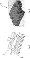
Fig. 5 shows an ice slide plate of the machine of the preceding figures; -
Fig. 6 shows a programming device of the machine of the preceding figures; -
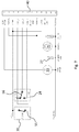
Fig. 7 is an electric diagram of the above machine; -
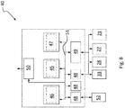
Fig. 8 is a block diagram of the programming device ofFig. 6 ; -
Fig. 9 is a block diagram of the refrigerator assembly of the above machine; -
Fig. 10 is an electric diagram of a variant of the above machine. - With reference to the above-listed drawings,
numeral 1 designates as a whole a machine for producing ice cubes according to the invention, which comprises a substantially parallelepipedexternal structure 2, basically consisting of a thermally insulating cabinet, withside walls front wall 5, arear wall 6, atop wall 7. - As can be seen, on the
front wall 5 there is an opening 9 with a diaphragm orclosing element 10 consisting of a door, a curtain or other similar component, which is adapted to close the opening 9 and prevent thermal dispersion towards the outside through it, while at the same time allowing access to the inside of themachine 1 for removing the ice. - On the
front wall 5,rear wall 6 andside wall 3 there are alsoair vents - The
structure 2 internally houses arefrigerator assembly 20 with acompressor 21, acondenser 22, anexpansion unit 23 and anevaporator 24; optionally, a tank S for the refrigerating fluid may also be included, especially in quite big machines. - The upper region of the
machine 1 accommodates the ice-forming part that comprises theevaporator 24, which is advantageously configured as a mould comprising cells orseats 25 for forming ice cubes. - The
evaporator 24 is arranged under thetop wall 7 of thestructure 2; underneath the evaporator there is aplate 29 for discharging the ice cubes; this plate is used as a chute for delivering the cubes falling from theevaporator 24 towards a containment drawer orvessel 30, from which they can be removed by a user, who can gain access to it through the front opening 10 of the structure. - The
plate 29 may have any appropriate design, though it is preferably of the type described in European patent applicationEP2584292 by the present Applicant, shown inFigure 5 . - For more details, reference should be made to said patent application; however, it is worth mentioning herein that the
slide plate 29 is equipped withnozzles 32 that, during the ice production cycle, spray water onto theevaporator 24. - For this purpose, the
nozzles 32 are fed by apump 33 that takes water from atub 34 and delivers it to the nozzles via adelivery header 35. - In the
machine 1 for ice production, a fast defrosting cycle of theevaporator 24 is carried out by circulating therein, the hot refrigerating fluid exiting thecompressor 21; to this end, therefrigerator assembly 20 includes a recirculation branch 26 (indicated by a dashed line inFigure 8 ), which extends from anelectrovalve 27 arranged downstream of thecompressor 21 up to theevaporator 24, so that in the latter a fraction of hot compressed fluid will circulate, thereby causing the ice to melt locally in the cells and to detach, dropping by gravity onto theplate 29 which will then divert it towards thecontainer 30. - In accordance with a preferred embodiment of the invention, the operation of the
machine 1 for ice production is governed by aprogramming device 40 to which the various components of the machine are different, including also, further to those taken into consideration so far, sensors and/or thermostats and or electrovalves, as shown in the diagram ofFigure 7 . - The
device 40 is essentially an electric controller, which may be appropriately designed as a function of the complexity of themachine 1 and of the operation thereof, as will be explained below. - It comprises electronic components that are per se known, such as a processor 45 (CPU) associated with a primary memory 47 (RAM) and a mass memory 46 (ROM), one or more analog-to-digital converters 48 (A/D), an
interface 49 for the machine components (compressor 21, electrovalve 27,temperature sensors 28,water pump 33, etc.), a communication interface 50 (SCI, Serial Communication Interface, or the like) for connecting theprogramming device 40 with the outside, preferably via an infrared, Bluetooth, Wi-Fi port or another electromagnetic-wave system, so that data can be exchanged (i.e. received and sent) with external apparatus such as electronic computers, whether fixed like a PC or portable like, for example, a tablet, as well as with other devices, including smartphones and data transmission networks (WAN, LAN, etc.).. - Preferably, the components of the
programming device 40 are operationally connected to one another via abus 51 and are electrically powered by theelectric system 52 of the machine; theprogramming device 40 may however be powered separately from themachine 1, possibly by batteries, so that it will be structurally and functionally independent. - Indeed, although the
programming device 40 is preferably housed inside thestructure 2 of the machine for ice production, it may however be installed outside thestructure 2, in the rear part thereof, as visible inFigure 2 , in which case, of course, it will have to be wired to the other components of themachine 1. - The latter operates as described below; in this regard, it must be said beforehand that the
programming device 40 allows the execution of different operating cycles of the machine by fully exploiting the components thereof not only for ice production, but also for other functions, such as automatic wash management and machine state checking, thus improving the overall performance. - The device provides immediate visual information about the producer's state (by means of LEDs or icons or other on-screen signals, not shown in the drawing), and simplifies the commands for maintaining the machine (pushbutton for automatic washing and defrosting).
- One of the configurations that the device may have is the following:
- ON/OFF button: turning on/ off the producer (green LED);
- Defrost button: defrosts the producer (yellow LED);
- Wash button: this button allows entering/exiting the automatic wash cycle (blue LED).
- When the producer is first started by pressing the ON/OFF button, the green LED will blink for a preset time (approx. 3 minutes). During this time interval, water is supplied into the internal tray, where ice will be produced.
- Without the present invention, this task would be carried out manually by the operator by pouring water from the front part of the internal cell or by manually forcing the defrosting step, during which also the water level for ice production is restored.
- Once started, the
machine 1 acquires the temperature (T_Box in the diagram ofFigure 7 ) in the ice container 30: if the latter is full of ice cubes, its temperature will be low (around 0 °C) and theswitch 55 will be opened by theprogramming device 40; in this condition, thecompressor 21 will be off and no water will be sprayed onto theevaporator 24. - The
machine 1 will remain in this condition until the temperature inside theice container 30 reaches a predefined level; theswitch 55 will then close the circuit to start thecompressor 21 and thewater pump 33 that feeds thenozzles 32. - Ice will form in the
moulds 25 of theevaporator 24, cooled by the fluid circulating in the refrigerator assembly; the system will remain in this state until ice cubes have completely formed on the moulds 25: this may occur after a time interval set by theprogrammer 40, or when a certain defrost temperature is reached on the evaporator 24 (T_Defr inFigure 7 ), detected by a switchingthermostat 56 similar to thethermostatic switch 55. - At this point the
electrovalve 27 will be turned on, and the hot fluid exiting thecompressor 21, or at least a part thereof, will be diverted into therecirculation branch 26 and will enter again theevaporator 24, thus warming it up and causing the ice to thaw locally and the ice cubes to drop from themoulds 25. - The above-described cycle is repeated until the level of the ice cubes in the
container 30 is restored and the temperature therein returns to a predefined value (T_Box), after which theswitch 55 will open and stop ice production. - As can be seen, as far as ice production is concerned, the
programming device 40 can perform those functions that, in prior-art machines, are governed by electromechanical timers, which are essentially cam-type mechanisms. - Unlike the latters, however, the
device 40 ensures better efficacy and accuracy because it controls the operation of the various components of the machine, not (only) on the basis of preset time intervals, but according to process parameters detected in operation. - This is the case, for example, of the temperatures (T Box, T_Defr) of the
ice container 30 and for defrosting theevaporator 24, which may be reached differently from time to time; for example, let us consider the different conditions in which a machine will have to work in summer and in winter: the different temperatures will affect the ice production cycle and the time needed for filling thecontainer 30. - The possibility of controlling the operation of the machine also according to such temperatures, allows adapting the production process to the actual environmental conditions.
- Furthermore, under an operating viewpoint, the
programming device 40 offers higher flexibility in controlling the operation of themachine 1, thereby improving the performance thereof. - Indeed, the
device 40 can be programmed in such a way as to carry out specific cycles as regards both ice production and maintenance and/or control of themachine 1. - As far as the former aspect is concerned, it is clear that the
processor 45, thememories - For example, in addition to the above observations about the temperature conditions in which the
machine 1 may have to operate, it must be pointed out that the working cycles may have different durations depending on the machines' productivity. - The same applies to different ice cubes, the shapes and dimensions of which can affect the above-described production process, requiring different cooling times and/or heat; likewise, the hourly amount of ice to be produced may vary among different machines.
- However, in all such cases the
programming device 40 is still the same: what changes is the programming thereof, which is adapted according to specific requirements. The programs are loaded into thememory communication interface 50. - They may however reside in such memories and/or in the
processor 45, depending on the design and electronic architecture chosen for theprogrammer 40. - Furthermore, according to a preferred embodiment, the data about the operation of the machine, such as duration and/or number of ice production cycles, temperature trend in the
container 30 and of the refrigerating fluid, activation times of thecompressor 21 and, more in general, of therefrigerator assembly 20, as well as any other parameters of the machine 1 (e.g. power consumption, refrigeration cycle pressures, etc.) are kept in thememories - Transmission and receiving of the data acquired by or stored in
programming device 40 occur by means of itscommunication interface 50, preferably via electromagnetic-wave transmission, such as infrared or radio frequency (e.g. Bluetooth, Wi Fi and the like); of course, other systems may also be used, such as, for example, a wired connection between theprogrammer 40 and a computer, or a USB port for connecting external storage means (e.g. pen drives, memory cards, hard disks, etc.) whereto the data can be downloaded and then transferred as desired. - Alongside these functions, the
programming device 40 can also have themachine 1 carry out other operations, in addition to ice production. - This is the case, for example, of the step of checking the operating state, which is activated when the machine is in operation by holding down the master on/ off
button 57 for a time interval of a few seconds, preferably 5 to 10 seconds. - If the button is pressed for a time shorter than this interval, the machine will be normally turned off; the start of this special function of the machine is preferably accompanied by a luminous signal, e.g. one or more lamps of the machine blinking simultaneously, or by an audible signal.
- Regardless of the signalling mode, when this step of pressing the
button 57 has been completed and the special machine check function has been started, the machine will take a specific reference configuration that may correspond to one of those adopted during ice production, during which the electric connections are checked. - It will thus be possible to verify, both during industrial production of the
machines 1 and in situ on machines installed at customers' sites, the electric features of both the machine and theprogrammer 40 by means of an automatic test, during which themachine 1 will be turned on and off in order to test its efficiency. - After the machine has been turned off automatically, if the test ended successfully the
machine 1 will restart automatically (i.e. without requiring pressing the on/ off button 57) and will work regularly for ice production, as previously explained. - The programming device also allows the execution of other functions of the
machine 1 for ice production, in addition or as an alternative to those already described; one of such functions concerns the washing of theevaporator 24. - In fact, the periodic maintenance of ice-producing machines includes cleaning those parts where ice cubes are formed, i.e. the moulds of the evaporator, in order to remove any lime deposits or fouling in general, which may cause the presence of dirt or germs and reduce the quality of the ice being produced.
- This maintenance step is usually carried out manually by an operator, who uses cloths and detergents for cleaning the surfaces involved.
- In order to overcome these drawbacks, according to a preferred embodiment of the invention the illustrated device teaches to carry out operations for washing the
evaporator 24 by spraying onto it, through thenozzles 32, water containing sanitizing and or cleaning substances, such as chlorine, soap, decalcifier and the like. - This allows cleaning the
moulds 25 for the ice cubes and also thenozzles 32 and all the other parts of the hydraulic circuit, such as thepump 33 and thetub 34, thus keeping thewhole machine 1 efficient, the latter remaining in operation during the washing. - During this step, the
programming device 40 stops thecompressor 21 but allows thepump 33 and the other components of the hydraulic circuit (e.g. water inlet and drain valves, not shown in the drawings, etc.) to operate. - Of course, also the washing of the
machine 1 can be executed in accordance with different programs stored in theprogramming device 40; for example, more or less intense programs may be available, with different durations and/or number of cycles of treatment with detergent, disinfectant, decalcifying watery solutions, which may vary as necessary. - Of course, the invention may be subject to a number of variations with respect to the description provided so far.
- First of all, it must be pointed out that the
programming device 40 may be designed in a different manner, e.g. with integrated components, so as to have smaller dimensions. - Likewise, also other special functions, in addition to the check of the efficiency of the machine components and to the washing function, may be governed by the
programmer 40; for example, these may include checking the energetic efficiency of the machine on the basis of the amount of ice produced (and therefore of the refrigeration units necessary for subtracting solidifying heat) and of the electric power absorbed by the refrigerator assembly. - Another variant can be obtained when the
condenser 22 is water cooled; in such a case, the air exchanger will be replaced in the machine with a water exchanger fed with mains water, possibly after the latter has been used for the ice. - According to a preferred embodiment, of which
Figure 10 shows an electric diagram, there is a further thermostatic switch 59 connected in series to the master defrosting switch T_Defr. - When the switch 59 is triggered, the
machine 1 will enter a state in which it will wait for the temperature of thecondenser 22 to be restored, similar to the state in which the machine waits for restoral of the temperature of theice container 30. - Further possible variants concern the
nozzles 32, which, as aforesaid, are preferably made in this example in accordance with the description provided inpatent application EP 2 053 323 by the present Applicant: this allows them, in fact, to be coplanar to thechute wall 29, thus facilitating the motion of the cubes towards thecontainer 30. - It is however apparent that other configurations are also possible for both the
nozzles 32 and the walls 39, such as, for example, those known in the art: what is important is, however, that the nozzles are adapted to spray water onto the evaporator not only for forming ice, but also for cleaning the evaporator in accordance with the teaching of the invention. - These and other equivalent variants will still fall within the scope of the following claims.
Claims (10)
- Machine for production of ice cubes and the like, comprising a refrigerator assembly (20) including at least one evaporator (24), means (32, 33, 34, 35) for supplying water to said at least one evaporator (24) for forming ice, characterized in that it comprises an electronic programming device (40) operationally connected to the refrigerator assembly (20) and to the water supply means (32, 33, 34, 35), thereby controlling the operation thereof.
- Machine according to claim 1, wherein the programming device (40) is adapted to check the state of the refrigerator assembly (20) and/or of the water supply means (32, 33, 34, 35) when the machine is started.
- Machine according to claims 1 or 2, comprising user-operated starting means (57) for starting it, wherein a step of checking the state of the refrigerator assembly (20) and/or of the water supply means (32, 33, 34, 35) is started via said starting means (57).
- Machine according to any one of the preceding claims, wherein the programming device (40) is adapted to carry out a cleaning step, during which the supply means (32, 33, 34, 35) spray a liquid onto the evaporator (24) for washing it.
- Machine according to claim 4, wherein during the washing step the refrigerator assembly (20), or at least the compressor thereof (21), is substantially inactive.
- Machine according to any one of the preceding claims, comprising a container (30) into which the ice cubes are collected, and wherein the programming device (40) controls the activation and/or deactivation of the refrigerator assembly (20) as a function of the temperature detected in the container (30).
- Machine according to any one of the preceding claims, wherein the refrigerator assembly (20) comprises a water-cooled condenser (22) and means for supplying water to said condenser (22), which are operationally connected to the programming device (40).
- Machine according to claim 7, wherein the means for supplying water to said condenser (22) comprise at least a part of those (32, 33, 34, 35) for supplying water to the evaporator (24).
- Machine according to any one of the preceding claims, wherein the programming device (40) is adapted to transmit and/or receive data relating to at least one of the following operating parameters: operating time, temperature of an ice collection container (30), defrosting temperature of the evaporator (24), temperature of the cooling water of the condenser (22), quantity of ice produced, electric power absorbed by the refrigerator assembly (20).
- Method for washing a machine according to any one of the preceding claims, comprising at least one step of cleaning the evaporator (24), characterized in that said cleaning step is at least partly carried out by spraying a liquid onto the evaporator (24) through the means (32, 33, 34, 35) for supplying water to said at least one evaporator (24) for forming ice.
Priority Applications (4)
| Application Number | Priority Date | Filing Date | Title |
|---|---|---|---|
| ES16425020T ES2729055T3 (en) | 2016-03-08 | 2016-03-08 | Ice production machine with electromechanical peripheral device and electronic automatic washing control device |
| EP16425020.1A EP3217124B1 (en) | 2016-03-08 | 2016-03-08 | Ice production machine with electromechanical peripheral apparatus and automatic washing control electronic device |
| KR1020170025227A KR20170104927A (en) | 2016-03-08 | 2017-02-27 | Ice production machine with electromechanical peripheral apparatus and automatic washing control electronic device |
| CN201710134414.7A CN107166833A (en) | 2016-03-08 | 2017-03-08 | Ice machine with electromechanical peripherals and automatic cleaning control electronic installation |
Applications Claiming Priority (1)
| Application Number | Priority Date | Filing Date | Title |
|---|---|---|---|
| EP16425020.1A EP3217124B1 (en) | 2016-03-08 | 2016-03-08 | Ice production machine with electromechanical peripheral apparatus and automatic washing control electronic device |
Publications (2)
| Publication Number | Publication Date |
|---|---|
| EP3217124A1 true EP3217124A1 (en) | 2017-09-13 |
| EP3217124B1 EP3217124B1 (en) | 2019-04-17 |
Family
ID=55806272
Family Applications (1)
| Application Number | Title | Priority Date | Filing Date |
|---|---|---|---|
| EP16425020.1A Active EP3217124B1 (en) | 2016-03-08 | 2016-03-08 | Ice production machine with electromechanical peripheral apparatus and automatic washing control electronic device |
Country Status (4)
| Country | Link |
|---|---|
| EP (1) | EP3217124B1 (en) |
| KR (1) | KR20170104927A (en) |
| CN (1) | CN107166833A (en) |
| ES (1) | ES2729055T3 (en) |
Citations (6)
| Publication number | Priority date | Publication date | Assignee | Title |
|---|---|---|---|---|
| US5289691A (en) * | 1992-12-11 | 1994-03-01 | The Manitowoc Company, Inc. | Self-cleaning self-sterilizing ice making machine |
| US20050044875A1 (en) * | 2003-08-29 | 2005-03-03 | Manitowoc Foodservice Companies, Inc. | Low-volume ice making machine |
| US20080092567A1 (en) * | 2006-10-20 | 2008-04-24 | Doberstein Andrew J | Ice maker with ice bin level control |
| EP2053323A1 (en) | 2006-09-01 | 2009-04-29 | Hoshizaki Denki Kabushiki Kaisha | Flow-down-type ice making machine |
| EP2584292A1 (en) | 2011-10-17 | 2013-04-24 | Brema Ice Makers SpA | Ice making machine with concealed water supply nozzles |
| US20140013781A1 (en) * | 2012-07-11 | 2014-01-16 | Manitowoc Foodservice Companies, Llc | Methods and apparatus for adjusting ice slab bridge thickness and initiate ice harvest following the freeze cycle |
Family Cites Families (5)
| Publication number | Priority date | Publication date | Assignee | Title |
|---|---|---|---|---|
| DE19538026A1 (en) * | 1995-10-12 | 1997-04-17 | Josef Hobelsberger | Device for producing pieces of ice |
| JP2002130879A (en) * | 2000-10-27 | 2002-05-09 | Meidensha Corp | Frozen drainage re-utilizing system |
| JP2005180823A (en) * | 2003-12-19 | 2005-07-07 | Hoshizaki Electric Co Ltd | Automatic ice making machine |
| CN101782306A (en) * | 2008-12-31 | 2010-07-21 | 曼尼托沃食品服务有限公司 | Ice maker with water inlet temperature detection and control method thereof |
| CN204141910U (en) * | 2014-09-25 | 2015-02-04 | 沧州冰雪制冷设备有限公司 | A kind of beverage ice machine |
-
2016
- 2016-03-08 EP EP16425020.1A patent/EP3217124B1/en active Active
- 2016-03-08 ES ES16425020T patent/ES2729055T3/en active Active
-
2017
- 2017-02-27 KR KR1020170025227A patent/KR20170104927A/en not_active Withdrawn
- 2017-03-08 CN CN201710134414.7A patent/CN107166833A/en active Pending
Patent Citations (6)
| Publication number | Priority date | Publication date | Assignee | Title |
|---|---|---|---|---|
| US5289691A (en) * | 1992-12-11 | 1994-03-01 | The Manitowoc Company, Inc. | Self-cleaning self-sterilizing ice making machine |
| US20050044875A1 (en) * | 2003-08-29 | 2005-03-03 | Manitowoc Foodservice Companies, Inc. | Low-volume ice making machine |
| EP2053323A1 (en) | 2006-09-01 | 2009-04-29 | Hoshizaki Denki Kabushiki Kaisha | Flow-down-type ice making machine |
| US20080092567A1 (en) * | 2006-10-20 | 2008-04-24 | Doberstein Andrew J | Ice maker with ice bin level control |
| EP2584292A1 (en) | 2011-10-17 | 2013-04-24 | Brema Ice Makers SpA | Ice making machine with concealed water supply nozzles |
| US20140013781A1 (en) * | 2012-07-11 | 2014-01-16 | Manitowoc Foodservice Companies, Llc | Methods and apparatus for adjusting ice slab bridge thickness and initiate ice harvest following the freeze cycle |
Also Published As
| Publication number | Publication date |
|---|---|
| CN107166833A (en) | 2017-09-15 |
| ES2729055T3 (en) | 2019-10-30 |
| KR20170104927A (en) | 2017-09-18 |
| EP3217124B1 (en) | 2019-04-17 |
Similar Documents
| Publication | Publication Date | Title |
|---|---|---|
| US11191419B2 (en) | Dishmachine | |
| EP2978360B1 (en) | Heat pump washing apparatus | |
| EP3170935B1 (en) | Washing machine | |
| JP5380311B2 (en) | Ice machine | |
| EP3008236A1 (en) | Washing machine | |
| WO2014116799A1 (en) | Ice maker with slide out sump | |
| US20180058743A1 (en) | Ice making system with provision for cleaning and cleaning method | |
| KR20100002897A (en) | An ice machine with sterilizer and method for cleaning thereof | |
| EP2880213B1 (en) | Washing machine | |
| EP3217124B1 (en) | Ice production machine with electromechanical peripheral apparatus and automatic washing control electronic device | |
| JP2574621Y2 (en) | Ice storage room cooling structure of automatic ice maker for block ice | |
| JP2670931B2 (en) | Operation control method of automatic ice maker for block ice | |
| JP2611876B2 (en) | Automatic ice maker for block ice | |
| JPS5813250Y2 (en) | automatic ice maker | |
| JP2670930B2 (en) | Operation control method of automatic ice maker for block ice | |
| CN117652986A (en) | Heat pump type dish washer | |
| JP2024054948A (en) | Ice maker | |
| JPH0512686Y2 (en) | ||
| HK1246388A1 (en) | Ice maker with reversing condenser fan motor to maintain clean condenser | |
| WO2007099453A2 (en) | Ice-making machine |
Legal Events
| Date | Code | Title | Description |
|---|---|---|---|
| PUAI | Public reference made under article 153(3) epc to a published international application that has entered the european phase |
Free format text: ORIGINAL CODE: 0009012 |
|
| STAA | Information on the status of an ep patent application or granted ep patent |
Free format text: STATUS: THE APPLICATION HAS BEEN PUBLISHED |
|
| AK | Designated contracting states |
Kind code of ref document: A1 Designated state(s): AL AT BE BG CH CY CZ DE DK EE ES FI FR GB GR HR HU IE IS IT LI LT LU LV MC MK MT NL NO PL PT RO RS SE SI SK SM TR |
|
| AX | Request for extension of the european patent |
Extension state: BA ME |
|
| STAA | Information on the status of an ep patent application or granted ep patent |
Free format text: STATUS: REQUEST FOR EXAMINATION WAS MADE |
|
| 17P | Request for examination filed |
Effective date: 20180308 |
|
| RBV | Designated contracting states (corrected) |
Designated state(s): AL AT BE BG CH CY CZ DE DK EE ES FI FR GB GR HR HU IE IS IT LI LT LU LV MC MK MT NL NO PL PT RO RS SE SI SK SM TR |
|
| RAP1 | Party data changed (applicant data changed or rights of an application transferred) |
Owner name: BREMA GROUP S.P.A. |
|
| GRAP | Despatch of communication of intention to grant a patent |
Free format text: ORIGINAL CODE: EPIDOSNIGR1 |
|
| STAA | Information on the status of an ep patent application or granted ep patent |
Free format text: STATUS: GRANT OF PATENT IS INTENDED |
|
| RIC1 | Information provided on ipc code assigned before grant |
Ipc: F25C 1/12 20060101AFI20181024BHEP |
|
| INTG | Intention to grant announced |
Effective date: 20181112 |
|
| RIN1 | Information on inventor provided before grant (corrected) |
Inventor name: CESARINO, MAROLI |
|
| GRAS | Grant fee paid |
Free format text: ORIGINAL CODE: EPIDOSNIGR3 |
|
| GRAA | (expected) grant |
Free format text: ORIGINAL CODE: 0009210 |
|
| STAA | Information on the status of an ep patent application or granted ep patent |
Free format text: STATUS: THE PATENT HAS BEEN GRANTED |
|
| AK | Designated contracting states |
Kind code of ref document: B1 Designated state(s): AL AT BE BG CH CY CZ DE DK EE ES FI FR GB GR HR HU IE IS IT LI LT LU LV MC MK MT NL NO PL PT RO RS SE SI SK SM TR |
|
| REG | Reference to a national code |
Ref country code: GB Ref legal event code: FG4D |
|
| REG | Reference to a national code |
Ref country code: CH Ref legal event code: EP |
|
| REG | Reference to a national code |
Ref country code: DE Ref legal event code: R096 Ref document number: 602016012530 Country of ref document: DE |
|
| REG | Reference to a national code |
Ref country code: AT Ref legal event code: REF Ref document number: 1121992 Country of ref document: AT Kind code of ref document: T Effective date: 20190515 Ref country code: IE Ref legal event code: FG4D |
|
| REG | Reference to a national code |
Ref country code: NL Ref legal event code: MP Effective date: 20190417 |
|
| REG | Reference to a national code |
Ref country code: LT Ref legal event code: MG4D |
|
| PG25 | Lapsed in a contracting state [announced via postgrant information from national office to epo] |
Ref country code: NL Free format text: LAPSE BECAUSE OF FAILURE TO SUBMIT A TRANSLATION OF THE DESCRIPTION OR TO PAY THE FEE WITHIN THE PRESCRIBED TIME-LIMIT Effective date: 20190417 |
|
| REG | Reference to a national code |
Ref country code: ES Ref legal event code: FG2A Ref document number: 2729055 Country of ref document: ES Kind code of ref document: T3 Effective date: 20191030 |
|
| PG25 | Lapsed in a contracting state [announced via postgrant information from national office to epo] |
Ref country code: NO Free format text: LAPSE BECAUSE OF FAILURE TO SUBMIT A TRANSLATION OF THE DESCRIPTION OR TO PAY THE FEE WITHIN THE PRESCRIBED TIME-LIMIT Effective date: 20190717 Ref country code: LT Free format text: LAPSE BECAUSE OF FAILURE TO SUBMIT A TRANSLATION OF THE DESCRIPTION OR TO PAY THE FEE WITHIN THE PRESCRIBED TIME-LIMIT Effective date: 20190417 Ref country code: FI Free format text: LAPSE BECAUSE OF FAILURE TO SUBMIT A TRANSLATION OF THE DESCRIPTION OR TO PAY THE FEE WITHIN THE PRESCRIBED TIME-LIMIT Effective date: 20190417 Ref country code: SE Free format text: LAPSE BECAUSE OF FAILURE TO SUBMIT A TRANSLATION OF THE DESCRIPTION OR TO PAY THE FEE WITHIN THE PRESCRIBED TIME-LIMIT Effective date: 20190417 Ref country code: HR Free format text: LAPSE BECAUSE OF FAILURE TO SUBMIT A TRANSLATION OF THE DESCRIPTION OR TO PAY THE FEE WITHIN THE PRESCRIBED TIME-LIMIT Effective date: 20190417 Ref country code: AL Free format text: LAPSE BECAUSE OF FAILURE TO SUBMIT A TRANSLATION OF THE DESCRIPTION OR TO PAY THE FEE WITHIN THE PRESCRIBED TIME-LIMIT Effective date: 20190417 Ref country code: PT Free format text: LAPSE BECAUSE OF FAILURE TO SUBMIT A TRANSLATION OF THE DESCRIPTION OR TO PAY THE FEE WITHIN THE PRESCRIBED TIME-LIMIT Effective date: 20190817 |
|
| PG25 | Lapsed in a contracting state [announced via postgrant information from national office to epo] |
Ref country code: GR Free format text: LAPSE BECAUSE OF FAILURE TO SUBMIT A TRANSLATION OF THE DESCRIPTION OR TO PAY THE FEE WITHIN THE PRESCRIBED TIME-LIMIT Effective date: 20190718 Ref country code: BG Free format text: LAPSE BECAUSE OF FAILURE TO SUBMIT A TRANSLATION OF THE DESCRIPTION OR TO PAY THE FEE WITHIN THE PRESCRIBED TIME-LIMIT Effective date: 20190717 Ref country code: RS Free format text: LAPSE BECAUSE OF FAILURE TO SUBMIT A TRANSLATION OF THE DESCRIPTION OR TO PAY THE FEE WITHIN THE PRESCRIBED TIME-LIMIT Effective date: 20190417 Ref country code: LV Free format text: LAPSE BECAUSE OF FAILURE TO SUBMIT A TRANSLATION OF THE DESCRIPTION OR TO PAY THE FEE WITHIN THE PRESCRIBED TIME-LIMIT Effective date: 20190417 Ref country code: PL Free format text: LAPSE BECAUSE OF FAILURE TO SUBMIT A TRANSLATION OF THE DESCRIPTION OR TO PAY THE FEE WITHIN THE PRESCRIBED TIME-LIMIT Effective date: 20190417 |
|
| REG | Reference to a national code |
Ref country code: AT Ref legal event code: MK05 Ref document number: 1121992 Country of ref document: AT Kind code of ref document: T Effective date: 20190417 |
|
| PG25 | Lapsed in a contracting state [announced via postgrant information from national office to epo] |
Ref country code: IS Free format text: LAPSE BECAUSE OF FAILURE TO SUBMIT A TRANSLATION OF THE DESCRIPTION OR TO PAY THE FEE WITHIN THE PRESCRIBED TIME-LIMIT Effective date: 20190817 |
|
| REG | Reference to a national code |
Ref country code: DE Ref legal event code: R097 Ref document number: 602016012530 Country of ref document: DE |
|
| PG25 | Lapsed in a contracting state [announced via postgrant information from national office to epo] |
Ref country code: SK Free format text: LAPSE BECAUSE OF FAILURE TO SUBMIT A TRANSLATION OF THE DESCRIPTION OR TO PAY THE FEE WITHIN THE PRESCRIBED TIME-LIMIT Effective date: 20190417 Ref country code: DK Free format text: LAPSE BECAUSE OF FAILURE TO SUBMIT A TRANSLATION OF THE DESCRIPTION OR TO PAY THE FEE WITHIN THE PRESCRIBED TIME-LIMIT Effective date: 20190417 Ref country code: CZ Free format text: LAPSE BECAUSE OF FAILURE TO SUBMIT A TRANSLATION OF THE DESCRIPTION OR TO PAY THE FEE WITHIN THE PRESCRIBED TIME-LIMIT Effective date: 20190417 Ref country code: AT Free format text: LAPSE BECAUSE OF FAILURE TO SUBMIT A TRANSLATION OF THE DESCRIPTION OR TO PAY THE FEE WITHIN THE PRESCRIBED TIME-LIMIT Effective date: 20190417 Ref country code: EE Free format text: LAPSE BECAUSE OF FAILURE TO SUBMIT A TRANSLATION OF THE DESCRIPTION OR TO PAY THE FEE WITHIN THE PRESCRIBED TIME-LIMIT Effective date: 20190417 Ref country code: RO Free format text: LAPSE BECAUSE OF FAILURE TO SUBMIT A TRANSLATION OF THE DESCRIPTION OR TO PAY THE FEE WITHIN THE PRESCRIBED TIME-LIMIT Effective date: 20190417 |
|
| PLBE | No opposition filed within time limit |
Free format text: ORIGINAL CODE: 0009261 |
|
| STAA | Information on the status of an ep patent application or granted ep patent |
Free format text: STATUS: NO OPPOSITION FILED WITHIN TIME LIMIT |
|
| PG25 | Lapsed in a contracting state [announced via postgrant information from national office to epo] |
Ref country code: SM Free format text: LAPSE BECAUSE OF FAILURE TO SUBMIT A TRANSLATION OF THE DESCRIPTION OR TO PAY THE FEE WITHIN THE PRESCRIBED TIME-LIMIT Effective date: 20190417 |
|
| 26N | No opposition filed |
Effective date: 20200120 |
|
| PGFP | Annual fee paid to national office [announced via postgrant information from national office to epo] |
Ref country code: DE Payment date: 20200331 Year of fee payment: 5 |
|
| PG25 | Lapsed in a contracting state [announced via postgrant information from national office to epo] |
Ref country code: SI Free format text: LAPSE BECAUSE OF FAILURE TO SUBMIT A TRANSLATION OF THE DESCRIPTION OR TO PAY THE FEE WITHIN THE PRESCRIBED TIME-LIMIT Effective date: 20190417 |
|
| PGFP | Annual fee paid to national office [announced via postgrant information from national office to epo] |
Ref country code: LU Payment date: 20200325 Year of fee payment: 5 Ref country code: BE Payment date: 20200325 Year of fee payment: 5 |
|
| PGFP | Annual fee paid to national office [announced via postgrant information from national office to epo] |
Ref country code: TR Payment date: 20200331 Year of fee payment: 5 Ref country code: FR Payment date: 20200326 Year of fee payment: 5 Ref country code: MT Payment date: 20200327 Year of fee payment: 5 |
|
| PGFP | Annual fee paid to national office [announced via postgrant information from national office to epo] |
Ref country code: CH Payment date: 20200420 Year of fee payment: 5 Ref country code: ES Payment date: 20200401 Year of fee payment: 5 Ref country code: IE Payment date: 20200409 Year of fee payment: 5 Ref country code: MC Payment date: 20200409 Year of fee payment: 5 |
|
| PGFP | Annual fee paid to national office [announced via postgrant information from national office to epo] |
Ref country code: GB Payment date: 20200401 Year of fee payment: 5 |
|
| REG | Reference to a national code |
Ref country code: DE Ref legal event code: R119 Ref document number: 602016012530 Country of ref document: DE |
|
| PG25 | Lapsed in a contracting state [announced via postgrant information from national office to epo] |
Ref country code: MC Free format text: LAPSE BECAUSE OF NON-PAYMENT OF DUE FEES Effective date: 20210331 Ref country code: IT Free format text: LAPSE BECAUSE OF NON-PAYMENT OF DUE FEES Effective date: 20200308 |
|
| REG | Reference to a national code |
Ref country code: CH Ref legal event code: PL |
|
| GBPC | Gb: european patent ceased through non-payment of renewal fee |
Effective date: 20210308 |
|
| REG | Reference to a national code |
Ref country code: BE Ref legal event code: MM Effective date: 20210331 |
|
| PG25 | Lapsed in a contracting state [announced via postgrant information from national office to epo] |
Ref country code: DE Free format text: LAPSE BECAUSE OF NON-PAYMENT OF DUE FEES Effective date: 20211001 Ref country code: FR Free format text: LAPSE BECAUSE OF NON-PAYMENT OF DUE FEES Effective date: 20210331 Ref country code: GB Free format text: LAPSE BECAUSE OF NON-PAYMENT OF DUE FEES Effective date: 20210308 Ref country code: IE Free format text: LAPSE BECAUSE OF NON-PAYMENT OF DUE FEES Effective date: 20210308 Ref country code: LU Free format text: LAPSE BECAUSE OF NON-PAYMENT OF DUE FEES Effective date: 20210308 Ref country code: LI Free format text: LAPSE BECAUSE OF NON-PAYMENT OF DUE FEES Effective date: 20210331 Ref country code: CH Free format text: LAPSE BECAUSE OF NON-PAYMENT OF DUE FEES Effective date: 20210331 |
|
| REG | Reference to a national code |
Ref country code: ES Ref legal event code: FD2A Effective date: 20220523 |
|
| PG25 | Lapsed in a contracting state [announced via postgrant information from national office to epo] |
Ref country code: CY Free format text: LAPSE BECAUSE OF FAILURE TO SUBMIT A TRANSLATION OF THE DESCRIPTION OR TO PAY THE FEE WITHIN THE PRESCRIBED TIME-LIMIT Effective date: 20190417 |
|
| PG25 | Lapsed in a contracting state [announced via postgrant information from national office to epo] |
Ref country code: MT Free format text: LAPSE BECAUSE OF NON-PAYMENT OF DUE FEES Effective date: 20210308 Ref country code: MK Free format text: LAPSE BECAUSE OF FAILURE TO SUBMIT A TRANSLATION OF THE DESCRIPTION OR TO PAY THE FEE WITHIN THE PRESCRIBED TIME-LIMIT Effective date: 20190417 |
|
| PG25 | Lapsed in a contracting state [announced via postgrant information from national office to epo] |
Ref country code: ES Free format text: LAPSE BECAUSE OF NON-PAYMENT OF DUE FEES Effective date: 20210309 Ref country code: BE Free format text: LAPSE BECAUSE OF NON-PAYMENT OF DUE FEES Effective date: 20210331 |
|
| P01 | Opt-out of the competence of the unified patent court (upc) registered |
Effective date: 20230601 |