EP3217049A1 - Sliding parts - Google Patents
Sliding parts Download PDFInfo
- Publication number
- EP3217049A1 EP3217049A1 EP15857699.1A EP15857699A EP3217049A1 EP 3217049 A1 EP3217049 A1 EP 3217049A1 EP 15857699 A EP15857699 A EP 15857699A EP 3217049 A1 EP3217049 A1 EP 3217049A1
- Authority
- EP
- European Patent Office
- Prior art keywords
- pressure generation
- groove
- negative pressure
- fluid
- grooves
- Prior art date
- Legal status (The legal status is an assumption and is not a legal conclusion. Google has not performed a legal analysis and makes no representation as to the accuracy of the status listed.)
- Granted
Links
Images



Classifications
-
- F—MECHANICAL ENGINEERING; LIGHTING; HEATING; WEAPONS; BLASTING
- F16—ENGINEERING ELEMENTS AND UNITS; GENERAL MEASURES FOR PRODUCING AND MAINTAINING EFFECTIVE FUNCTIONING OF MACHINES OR INSTALLATIONS; THERMAL INSULATION IN GENERAL
- F16J—PISTONS; CYLINDERS; SEALINGS
- F16J15/00—Sealings
- F16J15/16—Sealings between relatively-moving surfaces
- F16J15/40—Sealings between relatively-moving surfaces by means of fluid
-
- F—MECHANICAL ENGINEERING; LIGHTING; HEATING; WEAPONS; BLASTING
- F16—ENGINEERING ELEMENTS AND UNITS; GENERAL MEASURES FOR PRODUCING AND MAINTAINING EFFECTIVE FUNCTIONING OF MACHINES OR INSTALLATIONS; THERMAL INSULATION IN GENERAL
- F16J—PISTONS; CYLINDERS; SEALINGS
- F16J15/00—Sealings
- F16J15/16—Sealings between relatively-moving surfaces
- F16J15/34—Sealings between relatively-moving surfaces with slip-ring pressed against a more or less radial face on one member
-
- F—MECHANICAL ENGINEERING; LIGHTING; HEATING; WEAPONS; BLASTING
- F16—ENGINEERING ELEMENTS AND UNITS; GENERAL MEASURES FOR PRODUCING AND MAINTAINING EFFECTIVE FUNCTIONING OF MACHINES OR INSTALLATIONS; THERMAL INSULATION IN GENERAL
- F16J—PISTONS; CYLINDERS; SEALINGS
- F16J15/00—Sealings
- F16J15/16—Sealings between relatively-moving surfaces
- F16J15/34—Sealings between relatively-moving surfaces with slip-ring pressed against a more or less radial face on one member
- F16J15/3404—Sealings between relatively-moving surfaces with slip-ring pressed against a more or less radial face on one member and characterised by parts or details relating to lubrication, cooling or venting of the seal
- F16J15/3408—Sealings between relatively-moving surfaces with slip-ring pressed against a more or less radial face on one member and characterised by parts or details relating to lubrication, cooling or venting of the seal at least one ring having an uneven slipping surface
- F16J15/3412—Sealings between relatively-moving surfaces with slip-ring pressed against a more or less radial face on one member and characterised by parts or details relating to lubrication, cooling or venting of the seal at least one ring having an uneven slipping surface with cavities
-
- F—MECHANICAL ENGINEERING; LIGHTING; HEATING; WEAPONS; BLASTING
- F16—ENGINEERING ELEMENTS AND UNITS; GENERAL MEASURES FOR PRODUCING AND MAINTAINING EFFECTIVE FUNCTIONING OF MACHINES OR INSTALLATIONS; THERMAL INSULATION IN GENERAL
- F16J—PISTONS; CYLINDERS; SEALINGS
- F16J15/00—Sealings
- F16J15/16—Sealings between relatively-moving surfaces
- F16J15/34—Sealings between relatively-moving surfaces with slip-ring pressed against a more or less radial face on one member
- F16J15/3404—Sealings between relatively-moving surfaces with slip-ring pressed against a more or less radial face on one member and characterised by parts or details relating to lubrication, cooling or venting of the seal
- F16J15/3408—Sealings between relatively-moving surfaces with slip-ring pressed against a more or less radial face on one member and characterised by parts or details relating to lubrication, cooling or venting of the seal at least one ring having an uneven slipping surface
- F16J15/3412—Sealings between relatively-moving surfaces with slip-ring pressed against a more or less radial face on one member and characterised by parts or details relating to lubrication, cooling or venting of the seal at least one ring having an uneven slipping surface with cavities
- F16J15/342—Sealings between relatively-moving surfaces with slip-ring pressed against a more or less radial face on one member and characterised by parts or details relating to lubrication, cooling or venting of the seal at least one ring having an uneven slipping surface with cavities with means for feeding fluid directly to the face
Definitions
- the present invention relates to slide components suitable for, for example, mechanical seals, bearings, and other slide units, and in particular, relates to slide components such as seal rings or bearings that require friction reduction by interposing a fluid between sealing faces as well as prevention of fluid leakage from the sealing faces.
- a mechanical seal an example of a slide component, is evaluated for its performance by a leakage rate, a wear rate, and a torque.
- a leakage rate a leakage rate
- a wear rate a torque
- a torque a torque
- a type of antifreeze such as silicate or phosphate (hereinafter, referred to as a "deposit formation-causing substance”) can be concentrated on a sealing face, forming deposits as time passes, and degrading the function of the mechanical seal.
- the deposit formation is considered as a phenomenon that occurs likewise in mechanical seals of apparatuses that handle chemicals or oils.
- the present invention has an object of providing a slide component that can prevent deposit formation on a sealing face as well as promoting circulation of a fluid on sealing faces while fulfilling both conflicting conditions of sealing and lubrication, to maintain the sealing function of the sealing faces for a long period of time.
- a slide component includes a pair of slide parts that relatively slide on each other, one of the slide parts being provided, on a low-pressure side of a sealing face thereof, with a negative pressure generation mechanism including a negative pressure generation groove, the negative pressure generation groove communicating with a high-pressure fluid side and being separated from a low-pressure fluid side by a land portion, the other of the slide parts being provided, in a sealing face thereof, with at least one interference groove communicating with the high-pressure fluid side for producing pressure variations in a fluid in the negative pressure generation groove, the at least one interference groove having an end on an inside-diameter side extending to a position to radially overlap the negative pressure generation groove.
- the pressure difference between an upstream end and a downstream end of the negative pressure generation groove is brought into a state of being constantly varying, and the flow of the fluid in the negative pressure generation groove also varies repeatedly.
- the at least one interference groove includes a plurality of interference grooves provided circumferentially, the plurality of interference grooves is arranged such that when one of the interference grooves is in a position facing the upstream end of the negative pressure generation groove, the other interference grooves are not in a position facing the downstream end of the negative pressure generation groove.
- the pressure variations between the upstream end and the downstream end of the negative pressure generation groove can be produced greatly and reliably, and formation of deposits in the negative pressure generation groove can be further prevented.
- the negative pressure generation mechanism is formed from a reverse Rayleigh step mechanism.
- the negative pressure generation mechanism can be easily formed.
- the one slide part is provided, in the sealing face thereof, with a fluid circulation groove that communicates with the high-pressure fluid side via an inlet portion and an outlet portion and is separated from the low-pressure fluid side by a land portion, and the negative pressure generation groove has a downstream end communicating with the inlet portion of the fluid circulation groove.
- the one slide part is provided with a positive pressure generation mechanism including a positive pressure generation groove in a portion enclosed by the fluid circulation groove in the sealing face thereof and the high-pressure fluid side, and the positive pressure generation groove has an upstream side communicating with an inlet portion of the fluid circulation groove.
- the positive pressure generation mechanism is formed from a Rayleigh step mechanism.
- the positive pressure generation mechanism can be easily formed.
- the one slide part is a stationary-side seal ring
- the other slide part is a rotating-side seal ring
- the rotating-side seal ring is made larger in outside diameter and smaller in inside diameter than the stationary-side seal ring.
- the sealing face width depends on the stationary-side seal ring, which can reduce variation in the sealing face width.
- the present invention achieves outstanding effects as below.
- a mechanical seal an example of the slide component
- the outer peripheral side of slide parts constituting the mechanical seal is described as the high-pressure fluid side (sealed fluid side), and the inner peripheral side as the low-pressure fluid side (atmosphere side).
- the present invention is not limited to this, and is also applicable to a case where the high-pressure fluid side and the low-pressure fluid side are reversed.
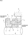
- Fig. 1 is a vertical cross-sectional view showing an example of the mechanical seal, which is an inside mechanical seal in a form of sealing a sealed fluid on the high-pressure fluid side tending to leak from the outer periphery of sealing faces toward the inner periphery.
- the mechanical seal is provided, on the side of a rotating shaft 2 to drive a rotor (e.g.
- a pump impeller not shown) on the high-pressure fluid side with a rotating-side seal ring 1 in an annular shape, one slide part, provided in a state of being rotatable with the rotating shaft 2 in an integrated manner via a sleeve 3 and a cup gasket 4, and at a housing 6, with a stationary-side seal ring 5 in an annular shape, the other slide part, provided in a state of being non-rotatable and axially movable.
- a coiled wave spring 7 and a bellows 8 axially biasing the stationary-side seal ring 5, the rotating-side seal ring 1 and the stationary-side seal ring 5 slide in close contact with each other on sealing portions S of sealing faces mirror-finished by lapping or the like. That is, the mechanical seal prevents the sealed fluid from flowing from the outer periphery of the rotating shaft 2 to the atmosphere side at the sealing portions S between the rotating-side seal ring 1 and the stationary-side seal ring 5.
- sealing face width of one of them is made larger, specifically, the outside diameter thereof is made larger and the inside diameter thereof is made smaller to form a sealing face margin So on the outside-diameter side and a sealing face margin Si on the inside-diameter side.
- sealing portions Ss portions on which the rotating-side seal ring 1 and the stationary-side seal ring 5 actually slide are referred to as sealing portions Ss, and a sealing face including sealing face margins is referred to as a sealing face S.
- Fig. 1 shows a case where the outside diameter of the rotating-side seal ring 1 is larger than the outside diameter of the stationary-side seal ring 5, and the inside diameter of the rotating-side seal ring 1 is smaller than the inside diameter of the stationary-side seal ring 5, and the sealing face margins are formed on the rotating-side seal ring 1.
- the present invention is not limited to this, and is also applicable to the opposite case as a matter of course.
- the outside-diameter side of the sealing faces S is the high-pressure fluid side
- the inside-diameter side is the low-pressure fluid side, for example, the atmosphere side.
- negative pressure generation mechanisms 10 each having a negative pressure generation groove 10a are provided on the low-pressure fluid side of the sealing face S of the stationary-side seal ring 5, that is, on the inner peripheral side.
- the negative pressure generation mechanisms 10 each having the negative pressure generation groove (dimple) 10a will be described below.
- the reverse Rayleigh step mechanisms 10 each have the negative pressure generation groove 10a and a reverse Rayleigh step 10c, and are provided in a circumferential direction.
- Fig. 2A eight reverse Rayleigh step mechanisms 10 are evenly spaced, which is not limiting. It is only necessary to provide at least one.
- the negative pressure generation groove (dimple) 10a constituting a part of the reverse Rayleigh step mechanisms 10 is isolated by a smooth portion R (sometimes referred to as a "land portion" in the present invention) of the sealing face S at its high-pressure fluid side and low-pressure fluid side, but a downstream end 10b thereof communicates with the high-pressure fluid side via a radial groove 11.
- the radial groove 11 communicates with the high-pressure fluid side, but does not communicate with the low-pressure fluid side.
- the negative pressure generation groove 10a is a shallow groove, and the radial groove 11 is a groove deeper than the negative pressure generation groove 10a.
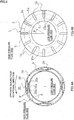
- the sealing face S of the rotating-side seal ring 1 is provided with interference grooves 15 for producing pressure variations in a fluid in the negative pressure generation grooves 10a.
- the interference grooves 15 communicate with the high-pressure fluid side, and are arranged radially in positions to produce pressure variations in the fluid in the negative pressure generation grooves 10a.
- the interference grooves 15 are provided in the sealing face margin So on the outside-diameter side and the sealing portion Ss to slide on the stationary-side seal ring 5, and their ends 15a on the inside-diameter side extend to positions to radially overlap the negative pressure generation grooves 10a.
- the shape of the interference grooves 15 illustrated in Fig. 2B is a substantially rectangular shape, but is not limited to this, and may be a circle, oval, or rhombus, for example. It is only essential that they communicate with the high-pressure fluid side, and the ends 15a on the inside-diameter side extend to positions to overlap the negative pressure generation grooves 10a.
- the depth of the interference grooves 15 is not particularly limited, but may be set the same as the depth of the radial grooves 11, or slightly deeper.
- three interference grooves 15 are evenly spaced circumferentially, which is not limiting. It is only necessary to provide at least one. Further, they need not be evenly spaced.
- the pressure of the fluid in the vicinity of the upstream end 10c increases.
- the other interference grooves 15 are set so as not to be in a position facing the downstream end 10b, there is no pressure increase of the fluid in the vicinity of the downstream end 10b.
- the pressure at the upstream end 10c is essentially a negative pressure, and there is a pressure difference between it and the pressure at the downstream end 10b.
- the interference groove 15 reaches the position facing the downstream end 10b of the negative pressure generation groove 10a, the pressure of the fluid in the vicinity of the downstream end 10b increases.
- the other interference grooves 15 are set so as not to be in a position facing the upstream end 10c, there is no pressure increase of the fluid in the vicinity of the upstream end 10c, and the difference between the pressure at the upstream end 10c and the pressure at the downstream end 10b increases.
- the action of the interference grooves 15 brings about a state where the pressure difference between the upstream end 10c and the downstream end 10b is constantly varying.
- the first embodiment achieves prominent effects as below.
- the second embodiment is different from the first embodiment in that fluid circulation grooves 20 are added in a sealing face S of a stationary-side seal ring 5, but the other basic configuration is the same as that in the first embodiment.
- the same numerals and symbols as those in the first embodiment denote the same members, and redundant descriptions will be omitted.
- the number of the fluid circulation grooves 20 is not limited to four. It is only necessary to provide at least one. Further, they need not be evenly spaced.
- the fluid circulation grooves 20 each include an inlet portion 20a for an entry from the high-pressure fluid side, an outlet portion 20b for an exit to the high-pressure fluid side, and a connection portion 20c circumferentially connecting the inlet portion 20a and the outlet portion 20b.
- the fluid circulation grooves 20 have the function of actively introducing a sealed fluid from the high-pressure fluid side into a sealing portion and discharging it in order to prevent a fluid containing corrosion products or the like from being concentrated on a sealing portion Ss, and are formed with wide mouths at the inlet portion 20a and the outlet portion 20b as shown in the figure to facilitate taking the sealed fluid into the sealing portion and discharging it in accordance with the rotation of the opposite sealing face, and on the other hand, are separated from the low-pressure fluid side by the land portion R to reduce leakage.
- the inlet portion 20a and the outlet portion 20b are formed in a linear shape, and form a substantially V shape, but are not particularly limited to this.
- the interior angle ⁇ between the inlet portion 20a and the outlet portion 20b may be further increased or reduced. They may be formed in a curved shape (such as an arc shape) instead of a linear shape.
- the width and depth of the fluid circulation grooves 20 are set optimally according to the pressure, type (viscosity), and others of the sealed fluid. An example of the depth is about 100 to 300 ⁇ m.
- the fluid circulation grooves 20 are not limited to the substantially V shape, and may be in a U shape, for example. It is only essential that the inlet portion 20a and the outlet portion 20b communicate with the high-pressure fluid side.
- four negative pressure generation mechanisms 10 are evenly spaced circumferentially in such a manner as to be located between adjacent fluid circulation grooves 20. Downstream ends 10b of negative pressure generation grooves 10a constituting the negative pressure generation mechanisms 10 communicate with the inlet portions 20a of the fluid circulation grooves 20, and the land portion R is present between upstream ends 10c and the outlet portions 20b of the fluid circulation grooves 20 on the upstream side.
- the inlet portions 20a of the fluid circulation grooves 20 also serve the function of the radial grooves 11 in the first embodiment.
- the interference grooves 15 are provided in a sealing face margin So on the outside-diameter side, and their ends 15a on the inside-diameter side extend to positions to radially overlap the negative pressure generation grooves 10a and the inlet portions 10a and the outlet portions 10b of the fluid circulation grooves 10.
- the twelve interference grooves 15 are evenly spaced circumferentially.
- the plurality of interference grooves 15 is arranged such that when one of the interference grooves 15 is in a position facing the upstream end 10c of a negative pressure generation groove 10a, the other interference grooves 15 are not in a position facing the downstream end 10b of the negative pressure generation groove 10a, and conversely, when one of the interference grooves 15 is in a position facing the downstream end 10b of a negative pressure generation groove 10a, the other interference grooves 15 are not in a position facing the upstream end 10c of the negative pressure generation groove 10a, and further, is arranged such that when one of the interference grooves 15 is in a position facing the inlet portion 20a of a fluid circulation groove 20, the other interference grooves 15 are not in a position facing the outlet portion 20b of the fluid circulation groove 20, and conversely, when one of the interference grooves 15 is in the position facing the outlet portion 20b, the other interference groove 15 are not in the position facing the inlet portion 20a
- the four negative pressure generation grooves 10a and the four fluid circulation grooves 20 are evenly spaced.
- the central angle ⁇ 1 between the upstream end 10c and the downstream end 10b of the negative pressure generation grooves 10a, and the central angle ⁇ 1 between the inlet portion 20a and the outlet portion 20b of the fluid circulation grooves 20 are each about 45°, whereas the central angle ⁇ between adjacent interference grooves 15 is 30°.
- the other interference grooves 15 are not in a position facing the downstream end 10b of the negative pressure generation groove 10a or the outlet portion 20b of the fluid circulation groove 20.
- the interference grooves 15 When attention is focused on the effects of the interference grooves 15 on the fluid circulation grooves 20, for example, when one of the interference grooves 15 reaches a position facing the inlet portion 20a of a fluid circulation groove 20, the pressure of a fluid in the inlet portion 20a increases. At this time, since the other interference grooves 15 are set so as not to be in a position facing the outlet portion 20b, there is no pressure increase of the fluid in the outlet portion 20b, resulting in the state, the pressure in the inlet portion 20a > the pressure in the outlet portion 20b.
- the interference groove 15 reaches the position facing the outlet portion 20b of the fluid circulation groove 20, the pressure of the fluid in the outlet portion 10b increases.
- the other interference grooves 15 are set so as not to be in a position facing the inlet portion 10b, there is no pressure increase of the fluid in the inlet portion 20b, resulting in the state, the pressure in the inlet portion 20a ⁇ the pressure in the outlet portion 20b.
- the action of the interference grooves 15 brings about a state where there is a pressure difference between the inlet portion 20a and the outlet portion 20b, which is constantly varying alternately.
- the second embodiment achieves prominent effects as below.
- the third embodiment is different from the second embodiment in that positive pressure generation mechanisms 25 are added on a sealing face S of a stationary-side seal ring 5, but the other basic configuration is the same as that in the second embodiment.
- the same numerals and symbols as those in the second embodiment denote the same members, and redundant descriptions will be omitted.
- the positive pressure generation mechanisms 25 each having a positive pressure generation groove 25a shallower than fluid circulation grooves 20 are provided in portions enclosed by the fluid circulation grooves 20 in the sealing face S of the stationary-side seal ring 5 and the high-pressure fluid side.
- the positive pressure generation mechanisms 25 are intended to generate positive pressure (dynamic pressure), thereby increasing a fluid film between sealing faces and increasing lubrication performance.
- the positive pressure generation grooves 25a have upstream ends 25c communicating with inlet portions 20a of the fluid circulation grooves 20, and downstream ends (also referred to as Rayleigh steps) 25b separated from outlet portions 20b of the fluid circulation grooves 20 by land portions R.
- the positive pressure generation grooves 25a are also separated from the high-pressure fluid side by the land portions R.
- each positive pressure generation mechanism 25 is formed from a Rayleigh step mechanism including the positive pressure generation groove 25a and the Rayleigh step 25b, but is not limited to this, and may be formed by a femto-groove with a dam, for example. It is only essential that it be a mechanism to generate positive pressure.
- the Rayleigh step mechanism will be described in detail below.
- interference grooves 15 on negative pressure generation grooves 10a and the fluid circulation grooves 20 are the same as those in the second embodiment.
- the interference grooves 15 When attention is focused on the effects of the interference grooves 15 on the positive pressure generation grooves 25a, for example, when one of the interference grooves 15 reaches the upstream end 25c of a positive pressure generation groove 25a, the pressure of a fluid in the vicinity of the upstream end 25c increases. At this time, the other interference grooves 15 are set so as not to be in a position facing the downstream end 25b, there is no pressure increase of the fluid in the vicinity of the downstream end 25b. In the positive pressure generation groove 25a, the pressure in the upstream end 25c is essentially smaller than that in the downstream end 25b. When the interference groove 15 reaches the upstream end 25c, the difference between the pressure at the upstream end 25c and the pressure at the downstream end 25b decreases.
- the interference groove 15 reaches a position facing the downstream end 25b of the positive pressure generation groove 25a, the pressure of the fluid in the vicinity of the downstream end 25b increases.
- the other interference grooves 15 are set so as not to be in a position facing the upstream end 25c, there is no pressure increase of the fluid in the vicinity of the upstream end 25c, and the difference between the pressure at the upstream end 25c and the pressure at the downstream end 25b increases.
- the action of the interference grooves 15 brings about a state where the pressure difference between the upstream end 25c and the downstream end 25b is constantly varying.
- the third embodiment achieves prominent effects as below.
- a positive pressure generation mechanism including a positive pressure generation groove (Rayleigh step mechanism) and a negative pressure generation mechanism including a negative pressure generation groove (reverse Rayleigh step mechanism) in the present invention will be described.
- Fig. 5A As shown by an arrow, the rotating-side seal ring 1 rotationally moves in a counterclockwise direction relative to the stationary-side seal ring 5.
- a positive pressure generation groove (dimple) 25a is formed in the sealing face S of the stationary-side seal ring 5
- a narrowed gap step, also referred to as a Rayleigh step
- the opposite sealing face of the rotating-side seal ring 1 is flat.
- Fig. 5B as shown by an arrow, the rotating-side seal ring 1 rotationally moves in a counterclockwise direction relative to the stationary-side seal ring 5.
- a negative pressure generation groove (dimple) 10a is formed in the sealing face S of the stationary-side seal ring 5
- a widened gap step, also referred to as a reverse Rayleigh step
- the opposite sealing face of the rotating-side seal ring 1 is flat.
- a slide part is used for one of a pair of a rotating seal ring and a stationary seal ring in a mechanical seal device
- it may be used as a slide part of a bearing that slides on a rotating shaft while sealing a lubricating oil on one side in an axial direction of a cylindrical sealing face.
- the present invention may be applied to a case where a high-pressure fluid is on the inner-peripheral side.
- fluid circulation grooves are provided in a stationary-side seal ring of a mechanical seal constituting a slide component, and interference grooves are provided in a rotating-side seal ring has been described, on the contrary, fluid circulation grooves may be provided in a rotating-side seal ring, and interference grooves in a stationary-side seal ring.
Landscapes
- Engineering & Computer Science (AREA)
- General Engineering & Computer Science (AREA)
- Mechanical Engineering (AREA)
- Mechanical Sealing (AREA)
Abstract
Description
- The present invention relates to slide components suitable for, for example, mechanical seals, bearings, and other slide units, and in particular, relates to slide components such as seal rings or bearings that require friction reduction by interposing a fluid between sealing faces as well as prevention of fluid leakage from the sealing faces.
- A mechanical seal, an example of a slide component, is evaluated for its performance by a leakage rate, a wear rate, and a torque. In conventional arts, by optimizing the seal material and the sealing face roughness of mechanical seals, their performance is increased to achieve low leakage, long life, and low torque. However, due to growing awareness of environmental problems in recent years, a further improvement in the performance of mechanical seals has been demanded, for which technology development beyond the limits of the conventional arts has been required.
- In that context, the present inventors have confirmed that in a mechanical seal of a water pump used for cooling a water-cooled engine, for example, an additive in LLC, a type of antifreeze, such as silicate or phosphate (hereinafter, referred to as a "deposit formation-causing substance") can be concentrated on a sealing face, forming deposits as time passes, and degrading the function of the mechanical seal. The deposit formation is considered as a phenomenon that occurs likewise in mechanical seals of apparatuses that handle chemicals or oils.
- There is a known conventional mechanical seal in which a sealing face is formed with grooves to form a fluid layer in order to prevent occurrence of wear or burn damage of sealing faces due to frictional heat generation (see
Patent Documents -
- Patent Document 1:
JP 07-180772 A - Patent Document 2:
JP 07-224948 A - Patent Document 3:
US 5,498,007 - The present invention has an object of providing a slide component that can prevent deposit formation on a sealing face as well as promoting circulation of a fluid on sealing faces while fulfilling both conflicting conditions of sealing and lubrication, to maintain the sealing function of the sealing faces for a long period of time.
- To attain the above object, a slide component according to a first aspect of the present invention includes a pair of slide parts that relatively slide on each other, one of the slide parts being provided, on a low-pressure side of a sealing face thereof, with a negative pressure generation mechanism including a negative pressure generation groove, the negative pressure generation groove communicating with a high-pressure fluid side and being separated from a low-pressure fluid side by a land portion, the other of the slide parts being provided, in a sealing face thereof, with at least one interference groove communicating with the high-pressure fluid side for producing pressure variations in a fluid in the negative pressure generation groove, the at least one interference groove having an end on an inside-diameter side extending to a position to radially overlap the negative pressure generation groove.
- According to this aspect, the pressure difference between an upstream end and a downstream end of the negative pressure generation groove is brought into a state of being constantly varying, and the flow of the fluid in the negative pressure generation groove also varies repeatedly. Thus, even when a sealed fluid contains a deposit formation-causing substance, formation of deposits in the negative pressure generation groove can be prevented, and the sealing function of the sealing faces can be maintained for a long period of time.
- According to a second aspect of the present invention, in the slide component according to the first aspect, the at least one interference groove includes a plurality of interference grooves provided circumferentially, the plurality of interference grooves is arranged such that when one of the interference grooves is in a position facing the upstream end of the negative pressure generation groove, the other interference grooves are not in a position facing the downstream end of the negative pressure generation groove.
- According to this aspect, the pressure variations between the upstream end and the downstream end of the negative pressure generation groove can be produced greatly and reliably, and formation of deposits in the negative pressure generation groove can be further prevented.
- According to a third aspect of the present invention, in the slide component according to the first or second aspect, the negative pressure generation mechanism is formed from a reverse Rayleigh step mechanism.
- According to this aspect, by providing a reverse Rayleigh step in the sealing face, the negative pressure generation mechanism can be easily formed.
- According to a fourth aspect of the present invention, in the slide component according to any one of the first to third aspects, the one slide part is provided, in the sealing face thereof, with a fluid circulation groove that communicates with the high-pressure fluid side via an inlet portion and an outlet portion and is separated from the low-pressure fluid side by a land portion, and the negative pressure generation groove has a downstream end communicating with the inlet portion of the fluid circulation groove.
- According to this aspect, there is a pressure difference between the inlet portion and the outlet portion of the fluid circulation groove, which is in a state of being constantly varying alternately, and the fluid in the fluid circulation groove repeats movements. Thus, in addition to the prevention of formation of deposits in the negative pressure generation groove, even when the sealed fluid contains a deposit formation-causing substance, formation of deposits in the fluid circulation groove can be prevented, and the sealing function of the sealing faces can be maintained for a long period of time.
- According to a fifth aspect of the present invention, in the slide component according to any one of the first to fourth aspects, the one slide part is provided with a positive pressure generation mechanism including a positive pressure generation groove in a portion enclosed by the fluid circulation groove in the sealing face thereof and the high-pressure fluid side, and the positive pressure generation groove has an upstream side communicating with an inlet portion of the fluid circulation groove.
- According to this aspect, in addition to the prevention of formation of deposits in the negative pressure generation groove and the fluid circulation groove, even when the sealed fluid contains a deposit formation-causing substance, formation of deposits in the positive pressure generation groove can be prevented, and the sealing function of the sealing faces can be maintained for a long period of time.
- According to a sixth aspect of the present invention, in the slide component according to the fifth aspect, the positive pressure generation mechanism is formed from a Rayleigh step mechanism.
- According to this aspect, by providing a Rayleigh step in the sealing face, the positive pressure generation mechanism can be easily formed.
- According to a seventh aspect of the present invention, in the slide component according to any one of the first to sixth aspects, the one slide part is a stationary-side seal ring, the other slide part is a rotating-side seal ring, and the rotating-side seal ring is made larger in outside diameter and smaller in inside diameter than the stationary-side seal ring.
- According to this aspect, the sealing face width depends on the stationary-side seal ring, which can reduce variation in the sealing face width.
- The present invention achieves outstanding effects as below.
- (1) A pair of slide parts that relatively slide on each other is included, one of the slide parts is provided, on a low-pressure side of a sealing face thereof, with a negative pressure generation mechanism including a negative pressure generation groove, the negative pressure generation groove communicates with a high-pressure fluid side and is separated from a low-pressure fluid side by a land portion, the other of the slide parts is provided, in a sealing face thereof, with at least one interference groove communicating with the high-pressure fluid side for producing pressure variations in a fluid in the negative pressure generation groove, and the at least one interference groove has an end on an inside-diameter side extending to a position to radially overlap the negative pressure generation groove, whereby the pressure difference between an upstream end and a downstream end of the negative pressure generation groove is brought into a state of being constantly varying, and the flow of a fluid in the negative pressure generation groove also varies repeatedly. Thus, even when a sealed fluid contains a deposit formation-causing substance, formation of deposits in the negative pressure generation groove can be prevented, and the sealing function of the sealing faces can be maintained for a long period of time.
- (2) The at least one interference groove includes a plurality of interference grooves provided circumferentially, and the plurality of interference grooves is arranged such that when one of the interference grooves is in a position facing an upstream end of the negative pressure generation groove, the other interference grooves are not in a position facing a downstream end of the negative pressure generation groove, whereby the pressure variations between the upstream end and the downstream end of the negative pressure generation groove can be produced greatly and reliably, and formation of deposits in the negative pressure generation groove can be further prevented.
- (3) The one slide part is provided, in the sealing face thereof, with a fluid circulation groove that communicates with the high-pressure fluid side via an inlet portion and an outlet portion and is separated from the low-pressure fluid side by the land portion, and the downstream end of the negative pressure generation groove communicates with the inlet portion of the fluid circulation groove, whereby there is a pressure difference between the inlet portion and the outlet portion of the fluid circulation groove, which is in a state of being constantly varying alternately, and the fluid in the fluid circulation groove repeats movements. Thus, in addition to the prevention of formation of deposits in the negative pressure generation groove, even when the sealed fluid contains a deposit formation-causing substance, formation of deposits in the fluid circulation groove can be prevented, and the sealing function of the sealing faces can be maintained for a long period of time.
- (4) The one slide part is provided with a positive pressure generation mechanism including a positive pressure generation groove in a portion enclosed by the fluid circulation groove in the sealing face thereof and the high-pressure fluid side, and the positive pressure generation groove has an upstream side communicating with the inlet portion of the fluid circulation groove, whereby in addition to the prevention of formation of deposits in the negative pressure generation groove and the fluid circulation groove, even when the sealed fluid contains a deposit formation-causing substance, formation of deposits in the positive pressure generation groove can be prevented, and the sealing function of the sealing faces can be maintained for a long period of time.
- (5) The one slide part is a stationary-side seal ring, the other slide part is a rotating-side seal ring, and the rotating-side seal ring is made larger in outside diameter and smaller in inside diameter than the stationary-side seal ring, whereby the sealing face width depends on the stationary-side seal ring, which can reduce variation in the sealing face width.
-
-
Fig. 1 is a vertical cross-sectional view showing an example of a mechanical seal according to a first embodiment of the present invention, showing an upper half thereof from the center of a rotating shaft; -
Fig. 2A shows the entire perimeter of a sealing face of a stationary-side seal ring inFig. 1 ; andFig. 2B shows the entire perimeter of a sealing face of a rotating-side seal ring inFig. 1 ; -
Fig. 3A shows the entire perimeter of a sealing face of a stationary-side seal ring in a second embodiment; andFig. 3B shows the entire perimeter of a sealing face of a rotating-side seal ring also in the second embodiment; -
Fig. 4A shows the entire perimeter of a sealing face of a stationary-side seal ring in a third embodiment; andFig. 4B shows the entire perimeter of a sealing face of a rotating-side seal ring also in the third embodiment; and -
Fig. 5A is a diagram for explaining a positive pressure generation mechanism including a narrowed gap (step) downstream of a dimple; andFig. 5B a negative pressure generation mechanism including a widened gap (step) upstream of a dimple. - Hereinafter with reference to the drawings, embodiments for implementing this invention will be described illustratively based on implementation examples. However, the dimensions, materials, shapes, relative arrangements, and others of components described in the embodiments are not intended to limit the scope of the present invention only to them unless otherwise described explicitly.
- With reference to
Fig. 1 andFigs. 2A and 2B , a slide component according to a first embodiment of the present invention will be described. - In the following embodiment, a mechanical seal, an example of the slide component, will be described as an example. The outer peripheral side of slide parts constituting the mechanical seal is described as the high-pressure fluid side (sealed fluid side), and the inner peripheral side as the low-pressure fluid side (atmosphere side). However, the present invention is not limited to this, and is also applicable to a case where the high-pressure fluid side and the low-pressure fluid side are reversed.
-
Fig. 1 is a vertical cross-sectional view showing an example of the mechanical seal, which is an inside mechanical seal in a form of sealing a sealed fluid on the high-pressure fluid side tending to leak from the outer periphery of sealing faces toward the inner periphery. The mechanical seal is provided, on the side of arotating shaft 2 to drive a rotor (e.g. a pump impeller not shown) on the high-pressure fluid side, with a rotating-side seal ring 1 in an annular shape, one slide part, provided in a state of being rotatable with therotating shaft 2 in an integrated manner via asleeve 3 and acup gasket 4, and at ahousing 6, with a stationary-side seal ring 5 in an annular shape, the other slide part, provided in a state of being non-rotatable and axially movable. By a coiledwave spring 7 and abellows 8 axially biasing the stationary-side seal ring 5, the rotating-side seal ring 1 and the stationary-side seal ring 5 slide in close contact with each other on sealing portions S of sealing faces mirror-finished by lapping or the like. That is, the mechanical seal prevents the sealed fluid from flowing from the outer periphery of therotating shaft 2 to the atmosphere side at the sealing portions S between the rotating-side seal ring 1 and the stationary-side seal ring 5. - In the mechanical seal, commonly, in order to accommodate a case where the rotation centers of the rotating-
side seal ring 1 and the stationary-side seal ring 5 do not strictly agree, the sealing face width of one of them is made larger, specifically, the outside diameter thereof is made larger and the inside diameter thereof is made smaller to form a sealing face margin So on the outside-diameter side and a sealing face margin Si on the inside-diameter side. In the present invention, portions on which the rotating-side seal ring 1 and the stationary-side seal ring 5 actually slide are referred to as sealing portions Ss, and a sealing face including sealing face margins is referred to as a sealing face S. -
Fig. 1 shows a case where the outside diameter of the rotating-side seal ring 1 is larger than the outside diameter of the stationary-side seal ring 5, and the inside diameter of the rotating-side seal ring 1 is smaller than the inside diameter of the stationary-side seal ring 5, and the sealing face margins are formed on the rotating-side seal ring 1. The present invention is not limited to this, and is also applicable to the opposite case as a matter of course. - In the case of
Fig. 1 , the sealing portion Ss and the sealing face S of the stationary-side seal ring 5 are the same. - With reference to
Figs. 2A and 2B , the shapes of the sealing faces S of the rotating-side seal ring 1 and the stationary-side seal ring 5 will be described. - In
Figs. 2A and 2B , the outside-diameter side of the sealing faces S is the high-pressure fluid side, and the inside-diameter side is the low-pressure fluid side, for example, the atmosphere side. - As shown in
Fig. 2A , negativepressure generation mechanisms 10 each having a negativepressure generation groove 10a are provided on the low-pressure fluid side of the sealing face S of the stationary-side seal ring 5, that is, on the inner peripheral side. - The negative
pressure generation mechanisms 10 each having the negative pressure generation groove (dimple) 10a will be described below. - In
Fig. 2A , as the negativepressure generation mechanisms 10, reverse Rayleigh step mechanisms are illustrated as an example. - The reverse
Rayleigh step mechanisms 10 each have the negativepressure generation groove 10a and areverse Rayleigh step 10c, and are provided in a circumferential direction. - In
Fig. 2A , eight reverseRayleigh step mechanisms 10 are evenly spaced, which is not limiting. It is only necessary to provide at least one. - The negative pressure generation groove (dimple) 10a constituting a part of the reverse
Rayleigh step mechanisms 10 is isolated by a smooth portion R (sometimes referred to as a "land portion" in the present invention) of the sealing face S at its high-pressure fluid side and low-pressure fluid side, but adownstream end 10b thereof communicates with the high-pressure fluid side via aradial groove 11. Theradial groove 11 communicates with the high-pressure fluid side, but does not communicate with the low-pressure fluid side. - The negative
pressure generation groove 10a is a shallow groove, and theradial groove 11 is a groove deeper than the negativepressure generation groove 10a. - As shown in
Fig. 2B , the sealing face S of the rotating-side seal ring 1 is provided withinterference grooves 15 for producing pressure variations in a fluid in the negativepressure generation grooves 10a. - The
interference grooves 15 communicate with the high-pressure fluid side, and are arranged radially in positions to produce pressure variations in the fluid in the negativepressure generation grooves 10a. - In the case of
Fig. 2 , theinterference grooves 15 are provided in the sealing face margin So on the outside-diameter side and the sealing portion Ss to slide on the stationary-side seal ring 5, and theirends 15a on the inside-diameter side extend to positions to radially overlap the negativepressure generation grooves 10a. - The shape of the
interference grooves 15 illustrated inFig. 2B is a substantially rectangular shape, but is not limited to this, and may be a circle, oval, or rhombus, for example. It is only essential that they communicate with the high-pressure fluid side, and theends 15a on the inside-diameter side extend to positions to overlap the negativepressure generation grooves 10a. - The depth of the
interference grooves 15 is not particularly limited, but may be set the same as the depth of theradial grooves 11, or slightly deeper. - In
Fig. 2B , threeinterference grooves 15 are evenly spaced circumferentially, which is not limiting. It is only necessary to provide at least one. Further, they need not be evenly spaced. - When the rotating-
side seal ring 1 is rotated, vortexes are formed in the vicinities of theinterference grooves 15, and theinterference grooves 15 accompanied by the vortexes move circumferentially. - Now, when one of the
interference grooves 15 reaches the upstream end (reverse Rayleigh step) 10c of a negativepressure generation groove 10a, the pressure of the fluid in the vicinity of theupstream end 10c increases. At this time, since theother interference grooves 15 are set so as not to be in a position facing thedownstream end 10b, there is no pressure increase of the fluid in the vicinity of thedownstream end 10b. In the negativepressure generation groove 10a, the pressure at theupstream end 10c is essentially a negative pressure, and there is a pressure difference between it and the pressure at thedownstream end 10b. When theinterference groove 15 reaches theupstream end 10c, the difference between the pressure at theupstream end 10c and the pressure at thedownstream end 10b decreases. - Next, when the
interference groove 15 reaches the position facing thedownstream end 10b of the negativepressure generation groove 10a, the pressure of the fluid in the vicinity of thedownstream end 10b increases. At this time, since theother interference grooves 15 are set so as not to be in a position facing theupstream end 10c, there is no pressure increase of the fluid in the vicinity of theupstream end 10c, and the difference between the pressure at theupstream end 10c and the pressure at thedownstream end 10b increases. - That is, when attention is focused on one negative
pressure generation groove 10a, the action of theinterference grooves 15 brings about a state where the pressure difference between theupstream end 10c and thedownstream end 10b is constantly varying. - In the state where the pressure difference between the
upstream end 10c and thedownstream end 10b is constantly varying, the flow of the fluid in the negativepressure generation groove 10a also varies repeatedly. Thus, even when the sealed fluid contains a deposit formation-causing substance, formation of deposits in the negativepressure generation grooves 10a is prevented. - The first embodiment achieves prominent effects as below.
- (1) The negative
pressure generation mechanisms 10 including the negativepressure generation grooves 10a are provided on the low-pressure side of the sealing face S of the stationary-side seal ring 5, the negativepressure generation grooves 10a communicate with the high-pressure fluid side, and are separated from the low-pressure fluid side by the land portion R, theinterference grooves 15 for producing pressure variations in the fluid in the negativepressure generation grooves 10a are provided in the sealing face S of the rotating-side seal ring 1 in such a manner as to communicate with the high-pressure fluid side, and theends 15a of theinterference grooves 15 on the inside-diameter side extend to the positions to radially overlap the negativepressure generation grooves 10a, so that the pressure difference between the upstream ends 10c and the downstream ends 10b of the negativepressure generation grooves 10a is brought into a state of being constantly varying, and the flow of the fluid in the negativepressure generation grooves 10a also varies repeatedly. Thus, even when the sealed fluid contains a deposit formation-causing substance, formation of deposits in the negativepressure generation grooves 10a can be prevented, and the sealing function of the sealing faces can be maintained for a long period of time. - (2) Since the rotating-
side seal ring 1 is made larger in outside diameter and smaller in inside diameter than the stationary-side seal ring 5, the sealing face width depends on the stationary-side seal ring 5. This can reduce variation in the sealing face width. - (3) Since the plurality of
interference grooves 15 is provided circumferentially, and the plurality ofinterference grooves 15 is arranged such that when one of theinterference grooves 15 is in a position facing theupstream end 10c of a negativepressure generation groove 10a, theother interference grooves 15 are not in a position facing thedownstream end 10b of the negativepressure generation groove 10a, and conversely, when one of theinterference grooves 15 is in a position facing thedownstream end 10b of a negativepressure generation groove 10a, theother interference grooves 15 are not in a position facing theupstream end 10c of the negativepressure generation groove 10a, the pressure variations between the upstream ends 10c and the downstream ends 10b of the negativepressure generation grooves 10a can be produced greatly and reliably, and formation of deposits in the negativepressure generation grooves 10a can be further prevented. - With reference to
Figs. 3A and 3B , a slide component according to a second embodiment of the present invention will be described. - The second embodiment is different from the first embodiment in that
fluid circulation grooves 20 are added in a sealing face S of a stationary-side seal ring 5, but the other basic configuration is the same as that in the first embodiment. The same numerals and symbols as those in the first embodiment denote the same members, and redundant descriptions will be omitted. - In
Fig. 3A , in the sealing face S of the stationary-side seal ring 5, fourfluid circulation grooves 20 communicating with the high-pressure fluid side and separated from the low-pressure fluid side by a smooth portion R (sometimes referred to as a "land portion" in the present invention) on the sealing face are evenly spaced circumferentially. - The number of the
fluid circulation grooves 20 is not limited to four. It is only necessary to provide at least one. Further, they need not be evenly spaced. - The
fluid circulation grooves 20 each include aninlet portion 20a for an entry from the high-pressure fluid side, anoutlet portion 20b for an exit to the high-pressure fluid side, and aconnection portion 20c circumferentially connecting theinlet portion 20a and theoutlet portion 20b. Thefluid circulation grooves 20 have the function of actively introducing a sealed fluid from the high-pressure fluid side into a sealing portion and discharging it in order to prevent a fluid containing corrosion products or the like from being concentrated on a sealing portion Ss, and are formed with wide mouths at theinlet portion 20a and theoutlet portion 20b as shown in the figure to facilitate taking the sealed fluid into the sealing portion and discharging it in accordance with the rotation of the opposite sealing face, and on the other hand, are separated from the low-pressure fluid side by the land portion R to reduce leakage. - In this embodiment, the
inlet portion 20a and theoutlet portion 20b are formed in a linear shape, and form a substantially V shape, but are not particularly limited to this. The interior angle α between theinlet portion 20a and theoutlet portion 20b may be further increased or reduced. They may be formed in a curved shape (such as an arc shape) instead of a linear shape. The width and depth of thefluid circulation grooves 20 are set optimally according to the pressure, type (viscosity), and others of the sealed fluid. An example of the depth is about 100 to 300 µm. - The
fluid circulation grooves 20 are not limited to the substantially V shape, and may be in a U shape, for example. It is only essential that theinlet portion 20a and theoutlet portion 20b communicate with the high-pressure fluid side. - In the sealing face S of the stationary-
side seal ring 5, four negativepressure generation mechanisms 10 are evenly spaced circumferentially in such a manner as to be located between adjacentfluid circulation grooves 20. Downstream ends 10b of negativepressure generation grooves 10a constituting the negativepressure generation mechanisms 10 communicate with theinlet portions 20a of thefluid circulation grooves 20, and the land portion R is present between upstream ends 10c and theoutlet portions 20b of thefluid circulation grooves 20 on the upstream side. - In the second embodiment, the
inlet portions 20a of thefluid circulation grooves 20 also serve the function of theradial grooves 11 in the first embodiment. - In a sealing face S of a rotating-
side seal ring 1, twelveinterference grooves 15 for producing pressure variations in the fluid in the negativepressure generation grooves 10a and thefluid circulation grooves 20 are evenly spaced. - In the case of
Fig. 3B , theinterference grooves 15 are provided in a sealing face margin So on the outside-diameter side, and theirends 15a on the inside-diameter side extend to positions to radially overlap the negativepressure generation grooves 10a and theinlet portions 10a and theoutlet portions 10b of thefluid circulation grooves 10. - In
Fig. 3B , the twelveinterference grooves 15 are evenly spaced circumferentially. The plurality ofinterference grooves 15 is arranged such that when one of theinterference grooves 15 is in a position facing theupstream end 10c of a negativepressure generation groove 10a, theother interference grooves 15 are not in a position facing thedownstream end 10b of the negativepressure generation groove 10a, and conversely, when one of theinterference grooves 15 is in a position facing thedownstream end 10b of a negativepressure generation groove 10a, theother interference grooves 15 are not in a position facing theupstream end 10c of the negativepressure generation groove 10a, and further, is arranged such that when one of theinterference grooves 15 is in a position facing theinlet portion 20a of afluid circulation groove 20, theother interference grooves 15 are not in a position facing theoutlet portion 20b of thefluid circulation groove 20, and conversely, when one of theinterference grooves 15 is in the position facing theoutlet portion 20b, theother interference groove 15 are not in the position facing theinlet portion 20a. - In the case of
Figs. 3A and 3B , the four negativepressure generation grooves 10a and the fourfluid circulation grooves 20 are evenly spaced. The central angle θ1 between theupstream end 10c and thedownstream end 10b of the negativepressure generation grooves 10a, and the central angle θ1 between theinlet portion 20a and theoutlet portion 20b of thefluid circulation grooves 20 are each about 45°, whereas the central angle θ betweenadjacent interference grooves 15 is 30°. Therefore, when the rotating-side seal ring 1 rotates, and one of theinterference grooves 15 is in a position facing theupstream end 10c of a negativepressure generation groove 10a or theinlet portion 20a of afluid circulation groove 20, theother interference grooves 15 are not in a position facing thedownstream end 10b of the negativepressure generation groove 10a or theoutlet portion 20b of thefluid circulation groove 20. - When the rotating-
side seal ring 1 is rotated, vortexes are formed in the vicinities of theinterference grooves 15, and theinterference grooves 15 accompanied by the vortexes move circumferentially. - The effects of the
interference grooves 15 on the negativepressure generation grooves 10a are the same as those in the first embodiment. - When attention is focused on the effects of the
interference grooves 15 on thefluid circulation grooves 20, for example, when one of theinterference grooves 15 reaches a position facing theinlet portion 20a of afluid circulation groove 20, the pressure of a fluid in theinlet portion 20a increases. At this time, since theother interference grooves 15 are set so as not to be in a position facing theoutlet portion 20b, there is no pressure increase of the fluid in theoutlet portion 20b, resulting in the state, the pressure in theinlet portion 20a > the pressure in theoutlet portion 20b. - Next, when the
interference groove 15 reaches the position facing theoutlet portion 20b of thefluid circulation groove 20, the pressure of the fluid in theoutlet portion 10b increases. At this time, since theother interference grooves 15 are set so as not to be in a position facing theinlet portion 10b, there is no pressure increase of the fluid in theinlet portion 20b, resulting in the state, the pressure in theinlet portion 20a < the pressure in theoutlet portion 20b. - That is, when attention is focused on one
fluid circulation groove 20, the action of theinterference grooves 15 brings about a state where there is a pressure difference between theinlet portion 20a and theoutlet portion 20b, which is constantly varying alternately. - In the state where there is a pressure difference between the
inlet portion 20a and theoutlet portion 20b, which is constantly varying alternately, the fluid in thefluid circulation groove 20 repeats movements. Thus, even when a sealed fluid contains a deposit formation-causing substance, formation of deposits in thefluid circulation grooves 20 can be prevented. - The second embodiment achieves prominent effects as below.
- (1) In the sealing face S of the stationary-
side seal ring 5, thefluid circulation grooves 20 communicating with the high-pressure fluid side via theinlet portions 20a and theoutlet portions 20b and separated from the low-pressure fluid side by the land portion R are provided, and the downstream ends 10b of the negativepressure generation grooves 10a communicate with theinlet portions 20a of thefluid circulation grooves 20. This brings about a state where there is a pressure difference between theinlet portions 20a and theoutlet portions 20b of thefluid circulation grooves 20, which is constantly varying alternately, and the fluid in thefluid circulation grooves 20 repeats movements. Thus, in addition to the prevention of formation of deposits in the negativepressure generation grooves 10a, even when the sealed fluid contains a deposit formation-causing substance, formation of deposits in thefluid circulation grooves 20 can be prevented, and the sealing function of the sealing faces can be maintained for a long period of time. - (2) Since the rotating-
side seal ring 1 is made larger in outside diameter and smaller in inside diameter than the stationary-side seal ring 5, the sealing face width depends on the stationary-side seal ring 5, which can reduce variation in the sealing face width. - (3) The plurality of
interference grooves 15 is provided circumferentially, and the plurality ofinterference grooves 15 is arranged such that when one of theinterference grooves 15 is in a position facing theupstream end 10c of a negativepressure generation groove 10a or theinlet portion 20a of afluid circulation groove 20, theother interference grooves 15 are not in a position facing thedownstream end 10b of the negativepressure generation groove 10a or theoutlet portion 20b of thefluid circulation groove 20, and conversely, when one of theinterference grooves 15 is in a position facing thedownstream end 10b of a negativepressure generation groove 10a or theoutlet portion 20b of afluid circulation groove 20, theother interference grooves 15 are not in a position facing theupstream end 10c of the negativepressure generation groove 10a or theinlet portion 20a of thefluid circulation groove 20. Thus, the pressure variations between the upstream ends 10c and the downstream ends 10b of the negativepressure generation grooves 10a can be produced greatly and reliably, and in addition, there is a pressure difference between theinlet portions 20a and theoutlet portions 20b of thefluid circulation grooves 20, which is in the state of being constantly varying alternately, and the fluid in the fluid circulation grooves repeats movements. Thus, formation of deposits in the negativepressure generation grooves 10a and thefluid circulation grooves 20 can be further prevented, and the sealing function of the sealing faces can be maintained for a long period of time. - With reference to
Figs. 4A and 4B , a slide component according to a third embodiment of the present invention will be described. - The third embodiment is different from the second embodiment in that positive
pressure generation mechanisms 25 are added on a sealing face S of a stationary-side seal ring 5, but the other basic configuration is the same as that in the second embodiment. The same numerals and symbols as those in the second embodiment denote the same members, and redundant descriptions will be omitted. - In
Fig. 4A , the positivepressure generation mechanisms 25 each having a positivepressure generation groove 25a shallower thanfluid circulation grooves 20 are provided in portions enclosed by thefluid circulation grooves 20 in the sealing face S of the stationary-side seal ring 5 and the high-pressure fluid side. - The positive
pressure generation mechanisms 25 are intended to generate positive pressure (dynamic pressure), thereby increasing a fluid film between sealing faces and increasing lubrication performance. - The positive
pressure generation grooves 25a haveupstream ends 25c communicating withinlet portions 20a of thefluid circulation grooves 20, and downstream ends (also referred to as Rayleigh steps) 25b separated fromoutlet portions 20b of thefluid circulation grooves 20 by land portions R. The positivepressure generation grooves 25a are also separated from the high-pressure fluid side by the land portions R. - In this embodiment, each positive
pressure generation mechanism 25 is formed from a Rayleigh step mechanism including the positivepressure generation groove 25a and theRayleigh step 25b, but is not limited to this, and may be formed by a femto-groove with a dam, for example. It is only essential that it be a mechanism to generate positive pressure. - The Rayleigh step mechanism will be described in detail below.
- When a rotating-
side seal ring 1 is rotated, vortexes are formed in the vicinities ofinterference grooves 15, and theinterference grooves 15 accompanied by the vortexes move circumferentially. - The effects of the
interference grooves 15 on negativepressure generation grooves 10a and thefluid circulation grooves 20 are the same as those in the second embodiment. - When attention is focused on the effects of the
interference grooves 15 on the positivepressure generation grooves 25a, for example, when one of theinterference grooves 15 reaches theupstream end 25c of a positivepressure generation groove 25a, the pressure of a fluid in the vicinity of theupstream end 25c increases. At this time, theother interference grooves 15 are set so as not to be in a position facing thedownstream end 25b, there is no pressure increase of the fluid in the vicinity of thedownstream end 25b. In the positivepressure generation groove 25a, the pressure in theupstream end 25c is essentially smaller than that in thedownstream end 25b. When theinterference groove 15 reaches theupstream end 25c, the difference between the pressure at theupstream end 25c and the pressure at thedownstream end 25b decreases. - Next, when the
interference groove 15 reaches a position facing thedownstream end 25b of the positivepressure generation groove 25a, the pressure of the fluid in the vicinity of thedownstream end 25b increases. At this time, theother interference grooves 15 are set so as not to be in a position facing theupstream end 25c, there is no pressure increase of the fluid in the vicinity of theupstream end 25c, and the difference between the pressure at theupstream end 25c and the pressure at thedownstream end 25b increases. - That is, when attention is focused on one positive
pressure generation groove 25a, the action of theinterference grooves 15 brings about a state where the pressure difference between theupstream end 25c and thedownstream end 25b is constantly varying. - In the state where the pressure difference between the
upstream end 25c and thedownstream end 25b is constantly varying, the flow of the fluid in the positivepressure generation groove 25a also varies repeatedly. Thus, even when a sealed fluid contains a deposit formation-causing substance, formation of deposits in the positivepressure generation grooves 25a can be prevented. - The third embodiment achieves prominent effects as below.
- (1) Since the positive
pressure generation mechanisms 25 including the positivepressure generation grooves 25a shallower than thefluid circulation grooves 20 are provided in the portions enclosed by thefluid circulation grooves 20 in the sealing face S of the stationary-side seal ring 5 and the high-pressure fluid side, and the upstream side of the positivepressure generation grooves 25a communicate with theinlet portions 20a of thefluid circulation grooves 20, in addition to the prevention of formation of deposits in the negativepressure generation grooves 10a and thefluid circulation grooves 20, even when the sealed fluid contains a deposit formation-causing substance, formation of deposits in the positivepressure generation grooves 25a can be prevented, and the sealing function of the sealing faces can be maintained for a long period of time. - Here, with reference to
Figs. 5A and 5B , a positive pressure generation mechanism including a positive pressure generation groove (Rayleigh step mechanism) and a negative pressure generation mechanism including a negative pressure generation groove (reverse Rayleigh step mechanism) in the present invention will be described. - In
Fig. 5A , as shown by an arrow, the rotating-side seal ring 1 rotationally moves in a counterclockwise direction relative to the stationary-side seal ring 5. When a positive pressure generation groove (dimple) 25a is formed in the sealing face S of the stationary-side seal ring 5, there is a narrowed gap (step, also referred to as a Rayleigh step) 25b downstream of thedimple 25a. The opposite sealing face of the rotating-side seal ring 1 is flat. - When the rotating-
side seal ring 1 relatively moves in a direction shown by the arrow, a fluid interposed between the sealing faces of the rotating-side seal ring 1 and the stationary-side seal ring 5 tends to follow it and move in the moving direction of the rotating-side seal ring 1 by its viscosity. At that time, due to the presence of the narrowed gap (step) 25b, dynamic pressure (positive pressure) as shown by broken lines is generated. - In
Fig. 5B , as shown by an arrow, the rotating-side seal ring 1 rotationally moves in a counterclockwise direction relative to the stationary-side seal ring 5. When a negative pressure generation groove (dimple) 10a is formed in the sealing face S of the stationary-side seal ring 5, there is a widened gap (step, also referred to as a reverse Rayleigh step) 10d upstream of thedimple 10a. The opposite sealing face of the rotating-side seal ring 1 is flat. When the rotating-side seal ring 1 relatively moves in a direction shown by the arrow, a fluid interposed between the sealing faces of the rotating-side seal ring 1 and the stationary-side seal ring 5 tends to follow it and move in the moving direction of the rotating-side seal ring 1 by its viscosity. At that time, due to the presence of the widened gap (step) 10d, dynamic pressure (negative pressure) as shown by broken lines is generated. - Therefore, negative pressure is generated upstream in the
dimple 10a, and positive pressure is generated downstream. Then, cavitation occurs in an upstream negative pressure generation region. - Although the embodiments of the present invention have been described above with reference to the drawings, its detailed configuration is not limited to the embodiments. Any changes and additions made without departing from the scope of the present invention are included in the present invention.
- For example, although in the above embodiments, an example in which a slide part is used for one of a pair of a rotating seal ring and a stationary seal ring in a mechanical seal device has been described, it may be used as a slide part of a bearing that slides on a rotating shaft while sealing a lubricating oil on one side in an axial direction of a cylindrical sealing face.
- Further, for example, although in the above embodiments, a case where a high-pressure sealed fluid is present on the outer-peripheral side has been described, the present invention may be applied to a case where a high-pressure fluid is on the inner-peripheral side.
- Further, for example, although in the above embodiments, a case where fluid circulation grooves are provided in a stationary-side seal ring of a mechanical seal constituting a slide component, and interference grooves are provided in a rotating-side seal ring has been described, on the contrary, fluid circulation grooves may be provided in a rotating-side seal ring, and interference grooves in a stationary-side seal ring.
-
- 1 rotating-side seal ring
- 2 rotating shaft
- 3 sleeve
- 4 cup gasket
- 5 stationary-side seal ring
- 6 housing
- 7 coiled wave spring
- 8 bellows
- 10 negative pressure generation mechanism (reverse Rayleigh step mechanism)
- 10a negative pressure generation groove (dimple)
- 10b downstream end
- 10c upstream end (reverse Rayleigh step)
- 11 radial groove
- 15 interference groove
- 15a end of the interference groove on the inside-diameter side
- 20 fluid circulation groove
- 20a inlet portion
- 20b outlet portion
- 20c connection portion
- 25 positive pressure generation mechanism
- 25a positive pressure generation groove
- 25b downstream end (Rayleigh step)
- 25c upstream end
- R land portion
- S sealing face
- Ss sealing portion
Claims (7)
- A slide component comprising:a pair of slide parts that relatively slide on each other,one of the slide parts being provided, on a low-pressure side of a sealing face thereof, with a negative pressure generation mechanism comprising a negative pressure generation groove, the negative pressure generation groove communicating with a high-pressure fluid side and being separated from a low-pressure fluid side by a land portion,the other of the slide parts being provided, in a sealing face thereof, with at least one interference groove communicating with the high-pressure fluid side for producing pressure variations in a fluid in the negative pressure generation groove, the at least one interference groove having an end on an inside-diameter side extending to a position to radially overlap the negative pressure generation groove.
- The slide component according to claim 1, wherein the at least one interference groove comprises a plurality of interference grooves provided circumferentially, the plurality of interference grooves being arranged such that when one of the interference grooves is in a position facing an upstream end of the negative pressure generation groove, the other interference grooves are not in a position facing a downstream end of the negative pressure generation groove.
- The slide component according to claim 1 or 2, wherein the negative pressure generation mechanism is formed from a reverse Rayleigh step mechanism.
- The slide component according to any one of claims 1 to 3, wherein
the one slide part is provided, in the sealing face thereof, with a fluid circulation groove that communicates with the high-pressure fluid side via an inlet portion and an outlet portion and is separated from the low-pressure fluid side by a land portion, and
the negative pressure generation groove has a downstream end communicating with the inlet portion of the fluid circulation groove. - The slide component according to any one of claims 1 to 4, wherein
the one slide part is provided with a positive pressure generation mechanism comprising a positive pressure generation groove in a portion enclosed by the fluid circulation groove in the sealing face thereof and the high-pressure fluid side, and
the positive pressure generation groove has an upstream side communicating with an inlet portion of the fluid circulation groove. - The slide component according to claim 5, wherein the positive pressure generation mechanism is formed from a Rayleigh step mechanism.
- The slide component according to any one of claims 1 to 6, wherein
the one slide part is a stationary-side seal ring,
the other slide part is a rotating-side seal ring, and the rotating-side seal ring is made larger in outside diameter and smaller in inside diameter than the stationary-side seal ring.
Applications Claiming Priority (2)
| Application Number | Priority Date | Filing Date | Title |
|---|---|---|---|
| JP2014227597 | 2014-11-08 | ||
| PCT/JP2015/080332 WO2016072325A1 (en) | 2014-11-08 | 2015-10-28 | Sliding parts |
Publications (3)
| Publication Number | Publication Date |
|---|---|
| EP3217049A1 true EP3217049A1 (en) | 2017-09-13 |
| EP3217049A4 EP3217049A4 (en) | 2018-07-11 |
| EP3217049B1 EP3217049B1 (en) | 2022-03-30 |
Family
ID=55909051
Family Applications (1)
| Application Number | Title | Priority Date | Filing Date |
|---|---|---|---|
| EP15857699.1A Active EP3217049B1 (en) | 2014-11-08 | 2015-10-28 | Sliding parts |
Country Status (6)
| Country | Link |
|---|---|
| US (1) | US10443737B2 (en) |
| EP (1) | EP3217049B1 (en) |
| JP (1) | JP6522000B2 (en) |
| CN (1) | CN107110370B (en) |
| AU (1) | AU2015344384A1 (en) |
| WO (1) | WO2016072325A1 (en) |
Cited By (16)
| Publication number | Priority date | Publication date | Assignee | Title |
|---|---|---|---|---|
| KR20200092400A (en) * | 2018-01-12 | 2020-08-03 | 이구루코교 가부시기가이샤 | Sliding parts |
| US11320052B2 (en) | 2018-02-01 | 2022-05-03 | Eagle Industry Co., Ltd. | Sliding components |
| US11913454B2 (en) | 2020-07-06 | 2024-02-27 | Eagle Industry Co., Ltd. | Sliding component |
| US11933303B2 (en) | 2020-07-06 | 2024-03-19 | Eagle Industry Co., Ltd. | Sliding component |
| US12104598B2 (en) | 2020-07-06 | 2024-10-01 | Eagle Industry Co., Ltd. | Eccentric sliding assembly with a plurality of dynamic pressure generation mechanisms |
| US12135030B2 (en) | 2020-07-06 | 2024-11-05 | Eagle Industry Co., Ltd. | Sliding component |
| US12152676B2 (en) | 2020-07-06 | 2024-11-26 | Eagle Industry Co., Ltd. | Sliding component |
| US12196320B2 (en) | 2020-03-31 | 2025-01-14 | Eagle Industry Co., Ltd. | Sliding component |
| US12209668B2 (en) | 2019-02-04 | 2025-01-28 | Eagle Industry Co., Ltd. | Sliding component |
| US12259043B2 (en) | 2019-02-04 | 2025-03-25 | Eagle Industry Co., Ltd. | Sliding component |
| US12404935B2 (en) | 2020-07-06 | 2025-09-02 | Eagle Industry Co., Ltd. | Sliding component |
| US12449040B2 (en) | 2020-05-11 | 2025-10-21 | Eagle Industry Co., Ltd. | Sliding component |
| US12467538B2 (en) | 2019-03-22 | 2025-11-11 | Eagle Industry Co., Ltd. | Sliding component |
| US12498044B2 (en) | 2019-02-04 | 2025-12-16 | Eagle Industry Co., Ltd. | Sliding component |
| US12560239B2 (en) | 2021-08-25 | 2026-02-24 | Eagle Industry Co., Ltd. | Sliding components |
| USRE50849E1 (en) | 2016-11-16 | 2026-03-31 | Eagle Industry Co., Ltd. | Sliding component |
Families Citing this family (13)
| Publication number | Priority date | Publication date | Assignee | Title |
|---|---|---|---|---|
| KR102288158B1 (en) * | 2016-11-14 | 2021-08-11 | 이구루코교 가부시기가이샤 | sliding parts |
| JP6910371B2 (en) * | 2016-11-14 | 2021-07-28 | イーグル工業株式会社 | Sliding parts |
| JP6941479B2 (en) * | 2017-05-26 | 2021-09-29 | 日本ピラー工業株式会社 | Seal structure and mechanical seal |
| EP3862600B1 (en) | 2018-10-01 | 2025-05-21 | Eagle Industry Co., Ltd. | Sliding member |
| CN112789434B (en) * | 2018-10-24 | 2023-09-29 | 伊格尔工业股份有限公司 | sliding parts |
| EP4253779B1 (en) | 2019-02-04 | 2024-12-18 | Eagle Industry Co., Ltd. | Sliding component and method for manufacturing sliding component |
| EP3922874A4 (en) * | 2019-02-04 | 2022-11-09 | Eagle Industry Co., Ltd. | SLIDING ELEMENT |
| KR102610647B1 (en) | 2019-02-04 | 2023-12-07 | 이구루코교 가부시기가이샤 | sliding parts |
| CN117432709A (en) | 2019-02-14 | 2024-01-23 | 伊格尔工业股份有限公司 | sliding parts |
| JP7374573B2 (en) | 2019-02-21 | 2023-11-07 | イーグル工業株式会社 | sliding parts |
| EP4306826A4 (en) * | 2021-03-12 | 2025-03-26 | Eagle Industry Co., Ltd. | SLIDING ELEMENT |
| CN113236781B (en) * | 2021-04-15 | 2022-04-15 | 大连理工大学 | A sealing ring with anti-friction heat dissipation structure on the end surface and its processing method |
| US12404936B2 (en) | 2021-09-28 | 2025-09-02 | Eagle Indusry Co., Ltd. | Sliding component |
Family Cites Families (24)
| Publication number | Priority date | Publication date | Assignee | Title |
|---|---|---|---|---|
| US3804424A (en) * | 1972-04-24 | 1974-04-16 | Crane Packing Co | Gap seal with thermal and pressure distortion compensation |
| JPS59110959A (en) * | 1982-12-15 | 1984-06-27 | Arai Pump Mfg Co Ltd | Mechanical seal |
| JPS59231268A (en) * | 1983-06-14 | 1984-12-25 | Arai Pump Mfg Co Ltd | Mechanical seal |
| JPS60167861A (en) * | 1984-02-10 | 1985-08-31 | Oomi Kenshi Kk | Automatic winder control method |
| CH677266A5 (en) * | 1986-10-28 | 1991-04-30 | Pacific Wietz Gmbh & Co Kg | |
| US5090712A (en) * | 1990-07-17 | 1992-02-25 | John Crane Inc. | Non-contacting, gap-type seal having a ring with a patterned microdam seal face |
| DE4303050B4 (en) * | 1992-02-26 | 2004-02-26 | Sedy, Josef, Mt. Prospect | Mechanical seal |
| JP2639883B2 (en) * | 1993-07-22 | 1997-08-13 | 日本ピラー工業株式会社 | Non-contact type shaft sealing device |
| JPH07180772A (en) | 1993-12-22 | 1995-07-18 | Mitsubishi Heavy Ind Ltd | Shaft seal device |
| US5498007A (en) | 1994-02-01 | 1996-03-12 | Durametallic Corporation | Double gas barrier seal |
| JPH07224948A (en) | 1994-02-15 | 1995-08-22 | Mitsubishi Heavy Ind Ltd | Mechanical seal |
| JP3781463B2 (en) | 1995-11-10 | 2006-05-31 | 株式会社ニクニ | mechanical seal |
| GB2375148A (en) * | 2001-04-30 | 2002-11-06 | Corac Group Plc | A dry gas seal |
| JP4719414B2 (en) * | 2003-12-22 | 2011-07-06 | イーグル工業株式会社 | Sliding parts |
| EP2549155B1 (en) * | 2010-03-15 | 2016-08-10 | Eagle Industry Co., Ltd. | Sliding member |
| CN103097782B (en) * | 2010-10-06 | 2016-01-20 | 伊格尔工业股份有限公司 | Slide member |
| WO2013035502A1 (en) * | 2011-09-10 | 2013-03-14 | イーグル工業株式会社 | Sliding component |
| JP2014083108A (en) * | 2012-10-19 | 2014-05-12 | Canon Inc | Mobile x-ray image capturing apparatus |
| US9964215B2 (en) * | 2012-12-25 | 2018-05-08 | Eagle Industry Co., Ltd. | Sliding component |
| EP2940354B1 (en) * | 2012-12-25 | 2018-06-13 | Eagle Industry Co., Ltd. | Sliding component |
| CN104736904B (en) * | 2013-01-16 | 2017-04-05 | 伊格尔工业股份有限公司 | Slide unit |
| CN103133696A (en) * | 2013-02-22 | 2013-06-05 | 江苏大学 | Dynamic pressure mechanical sealing ring for automatically draining particle type fluids |
| CN105683632B (en) * | 2013-11-22 | 2017-07-07 | 伊格尔工业股份有限公司 | Slide unit |
| EP3112078B1 (en) * | 2014-02-24 | 2020-04-15 | Eagle Industry Co., Ltd. | Sliding member and sliding member processing method |
-
2015
- 2015-10-28 US US15/521,608 patent/US10443737B2/en active Active
- 2015-10-28 EP EP15857699.1A patent/EP3217049B1/en active Active
- 2015-10-28 WO PCT/JP2015/080332 patent/WO2016072325A1/en not_active Ceased
- 2015-10-28 AU AU2015344384A patent/AU2015344384A1/en not_active Abandoned
- 2015-10-28 JP JP2016557725A patent/JP6522000B2/en active Active
- 2015-10-28 CN CN201580058043.8A patent/CN107110370B/en active Active
Cited By (19)
| Publication number | Priority date | Publication date | Assignee | Title |
|---|---|---|---|---|
| USRE50849E1 (en) | 2016-11-16 | 2026-03-31 | Eagle Industry Co., Ltd. | Sliding component |
| KR20200092400A (en) * | 2018-01-12 | 2020-08-03 | 이구루코교 가부시기가이샤 | Sliding parts |
| EP3739242A4 (en) * | 2018-01-12 | 2021-10-13 | Eagle Industry Co., Ltd. | SLIDING ELEMENT |
| US11603934B2 (en) | 2018-01-12 | 2023-03-14 | Eagle Industry Co., Ltd. | Sliding component |
| US11320052B2 (en) | 2018-02-01 | 2022-05-03 | Eagle Industry Co., Ltd. | Sliding components |
| US11619308B2 (en) | 2018-02-01 | 2023-04-04 | Eagle Industry Co., Ltd. | Sliding components |
| US12259043B2 (en) | 2019-02-04 | 2025-03-25 | Eagle Industry Co., Ltd. | Sliding component |
| US12209668B2 (en) | 2019-02-04 | 2025-01-28 | Eagle Industry Co., Ltd. | Sliding component |
| US12498044B2 (en) | 2019-02-04 | 2025-12-16 | Eagle Industry Co., Ltd. | Sliding component |
| US12467538B2 (en) | 2019-03-22 | 2025-11-11 | Eagle Industry Co., Ltd. | Sliding component |
| US12196320B2 (en) | 2020-03-31 | 2025-01-14 | Eagle Industry Co., Ltd. | Sliding component |
| US12449040B2 (en) | 2020-05-11 | 2025-10-21 | Eagle Industry Co., Ltd. | Sliding component |
| US12104598B2 (en) | 2020-07-06 | 2024-10-01 | Eagle Industry Co., Ltd. | Eccentric sliding assembly with a plurality of dynamic pressure generation mechanisms |
| US12135030B2 (en) | 2020-07-06 | 2024-11-05 | Eagle Industry Co., Ltd. | Sliding component |
| US12152676B2 (en) | 2020-07-06 | 2024-11-26 | Eagle Industry Co., Ltd. | Sliding component |
| US11933303B2 (en) | 2020-07-06 | 2024-03-19 | Eagle Industry Co., Ltd. | Sliding component |
| US12404935B2 (en) | 2020-07-06 | 2025-09-02 | Eagle Industry Co., Ltd. | Sliding component |
| US11913454B2 (en) | 2020-07-06 | 2024-02-27 | Eagle Industry Co., Ltd. | Sliding component |
| US12560239B2 (en) | 2021-08-25 | 2026-02-24 | Eagle Industry Co., Ltd. | Sliding components |
Also Published As
| Publication number | Publication date |
|---|---|
| EP3217049A4 (en) | 2018-07-11 |
| JPWO2016072325A1 (en) | 2017-10-05 |
| JP6522000B2 (en) | 2019-05-29 |
| US10443737B2 (en) | 2019-10-15 |
| AU2015344384A1 (en) | 2017-04-27 |
| CN107110370B (en) | 2019-09-13 |
| CN107110370A (en) | 2017-08-29 |
| EP3217049B1 (en) | 2022-03-30 |
| WO2016072325A1 (en) | 2016-05-12 |
| US20170241549A1 (en) | 2017-08-24 |
Similar Documents
| Publication | Publication Date | Title |
|---|---|---|
| EP3217049B1 (en) | Sliding parts | |
| US10274086B2 (en) | Sliding component | |
| US11053974B2 (en) | Sliding component | |
| EP3540274B1 (en) | Sliding component | |
| US11009072B2 (en) | Sliding component | |
| EP3315832B1 (en) | Sliding component | |
| EP3299685B1 (en) | Sliding component | |
| US9677670B2 (en) | Sliding parts | |
| WO2018139232A1 (en) | Sliding component | |
| WO2015087799A1 (en) | Sliding component | |
| US10344867B2 (en) | Sliding component |
Legal Events
| Date | Code | Title | Description |
|---|---|---|---|
| STAA | Information on the status of an ep patent application or granted ep patent |
Free format text: STATUS: THE INTERNATIONAL PUBLICATION HAS BEEN MADE |
|
| PUAI | Public reference made under article 153(3) epc to a published international application that has entered the european phase |
Free format text: ORIGINAL CODE: 0009012 |
|
| STAA | Information on the status of an ep patent application or granted ep patent |
Free format text: STATUS: REQUEST FOR EXAMINATION WAS MADE |
|
| 17P | Request for examination filed |
Effective date: 20170419 |
|
| AK | Designated contracting states |
Kind code of ref document: A1 Designated state(s): AL AT BE BG CH CY CZ DE DK EE ES FI FR GB GR HR HU IE IS IT LI LT LU LV MC MK MT NL NO PL PT RO RS SE SI SK SM TR |
|
| AX | Request for extension of the european patent |
Extension state: BA ME |
|
| DAV | Request for validation of the european patent (deleted) | ||
| DAX | Request for extension of the european patent (deleted) | ||
| A4 | Supplementary search report drawn up and despatched |
Effective date: 20180611 |
|
| RIC1 | Information provided on ipc code assigned before grant |
Ipc: F16J 15/34 20060101AFI20180605BHEP |
|
| GRAP | Despatch of communication of intention to grant a patent |
Free format text: ORIGINAL CODE: EPIDOSNIGR1 |
|
| STAA | Information on the status of an ep patent application or granted ep patent |
Free format text: STATUS: GRANT OF PATENT IS INTENDED |
|
| INTG | Intention to grant announced |
Effective date: 20211213 |
|
| GRAS | Grant fee paid |
Free format text: ORIGINAL CODE: EPIDOSNIGR3 |
|
| GRAA | (expected) grant |
Free format text: ORIGINAL CODE: 0009210 |
|
| STAA | Information on the status of an ep patent application or granted ep patent |
Free format text: STATUS: THE PATENT HAS BEEN GRANTED |
|
| AK | Designated contracting states |
Kind code of ref document: B1 Designated state(s): AL AT BE BG CH CY CZ DE DK EE ES FI FR GB GR HR HU IE IS IT LI LT LU LV MC MK MT NL NO PL PT RO RS SE SI SK SM TR |
|
| REG | Reference to a national code |
Ref country code: GB Ref legal event code: FG4D |
|
| REG | Reference to a national code |
Ref country code: CH Ref legal event code: EP |
|
| REG | Reference to a national code |
Ref country code: AT Ref legal event code: REF Ref document number: 1479486 Country of ref document: AT Kind code of ref document: T Effective date: 20220415 |
|
| REG | Reference to a national code |
Ref country code: DE Ref legal event code: R096 Ref document number: 602015077933 Country of ref document: DE |
|
| REG | Reference to a national code |
Ref country code: IE Ref legal event code: FG4D |
|
| REG | Reference to a national code |
Ref country code: LT Ref legal event code: MG9D |
|
| PG25 | Lapsed in a contracting state [announced via postgrant information from national office to epo] |
Ref country code: SE Free format text: LAPSE BECAUSE OF FAILURE TO SUBMIT A TRANSLATION OF THE DESCRIPTION OR TO PAY THE FEE WITHIN THE PRESCRIBED TIME-LIMIT Effective date: 20220330 Ref country code: RS Free format text: LAPSE BECAUSE OF FAILURE TO SUBMIT A TRANSLATION OF THE DESCRIPTION OR TO PAY THE FEE WITHIN THE PRESCRIBED TIME-LIMIT Effective date: 20220330 Ref country code: NO Free format text: LAPSE BECAUSE OF FAILURE TO SUBMIT A TRANSLATION OF THE DESCRIPTION OR TO PAY THE FEE WITHIN THE PRESCRIBED TIME-LIMIT Effective date: 20220630 Ref country code: LT Free format text: LAPSE BECAUSE OF FAILURE TO SUBMIT A TRANSLATION OF THE DESCRIPTION OR TO PAY THE FEE WITHIN THE PRESCRIBED TIME-LIMIT Effective date: 20220330 Ref country code: HR Free format text: LAPSE BECAUSE OF FAILURE TO SUBMIT A TRANSLATION OF THE DESCRIPTION OR TO PAY THE FEE WITHIN THE PRESCRIBED TIME-LIMIT Effective date: 20220330 Ref country code: BG Free format text: LAPSE BECAUSE OF FAILURE TO SUBMIT A TRANSLATION OF THE DESCRIPTION OR TO PAY THE FEE WITHIN THE PRESCRIBED TIME-LIMIT Effective date: 20220630 |
|
| REG | Reference to a national code |
Ref country code: NL Ref legal event code: MP Effective date: 20220330 |
|
| REG | Reference to a national code |
Ref country code: AT Ref legal event code: MK05 Ref document number: 1479486 Country of ref document: AT Kind code of ref document: T Effective date: 20220330 |
|
| PG25 | Lapsed in a contracting state [announced via postgrant information from national office to epo] |
Ref country code: LV Free format text: LAPSE BECAUSE OF FAILURE TO SUBMIT A TRANSLATION OF THE DESCRIPTION OR TO PAY THE FEE WITHIN THE PRESCRIBED TIME-LIMIT Effective date: 20220330 Ref country code: GR Free format text: LAPSE BECAUSE OF FAILURE TO SUBMIT A TRANSLATION OF THE DESCRIPTION OR TO PAY THE FEE WITHIN THE PRESCRIBED TIME-LIMIT Effective date: 20220701 Ref country code: FI Free format text: LAPSE BECAUSE OF FAILURE TO SUBMIT A TRANSLATION OF THE DESCRIPTION OR TO PAY THE FEE WITHIN THE PRESCRIBED TIME-LIMIT Effective date: 20220330 |
|
| PG25 | Lapsed in a contracting state [announced via postgrant information from national office to epo] |
Ref country code: NL Free format text: LAPSE BECAUSE OF FAILURE TO SUBMIT A TRANSLATION OF THE DESCRIPTION OR TO PAY THE FEE WITHIN THE PRESCRIBED TIME-LIMIT Effective date: 20220330 |
|
| PG25 | Lapsed in a contracting state [announced via postgrant information from national office to epo] |
Ref country code: SM Free format text: LAPSE BECAUSE OF FAILURE TO SUBMIT A TRANSLATION OF THE DESCRIPTION OR TO PAY THE FEE WITHIN THE PRESCRIBED TIME-LIMIT Effective date: 20220330 Ref country code: SK Free format text: LAPSE BECAUSE OF FAILURE TO SUBMIT A TRANSLATION OF THE DESCRIPTION OR TO PAY THE FEE WITHIN THE PRESCRIBED TIME-LIMIT Effective date: 20220330 Ref country code: RO Free format text: LAPSE BECAUSE OF FAILURE TO SUBMIT A TRANSLATION OF THE DESCRIPTION OR TO PAY THE FEE WITHIN THE PRESCRIBED TIME-LIMIT Effective date: 20220330 Ref country code: PT Free format text: LAPSE BECAUSE OF FAILURE TO SUBMIT A TRANSLATION OF THE DESCRIPTION OR TO PAY THE FEE WITHIN THE PRESCRIBED TIME-LIMIT Effective date: 20220801 Ref country code: ES Free format text: LAPSE BECAUSE OF FAILURE TO SUBMIT A TRANSLATION OF THE DESCRIPTION OR TO PAY THE FEE WITHIN THE PRESCRIBED TIME-LIMIT Effective date: 20220330 Ref country code: EE Free format text: LAPSE BECAUSE OF FAILURE TO SUBMIT A TRANSLATION OF THE DESCRIPTION OR TO PAY THE FEE WITHIN THE PRESCRIBED TIME-LIMIT Effective date: 20220330 Ref country code: CZ Free format text: LAPSE BECAUSE OF FAILURE TO SUBMIT A TRANSLATION OF THE DESCRIPTION OR TO PAY THE FEE WITHIN THE PRESCRIBED TIME-LIMIT Effective date: 20220330 Ref country code: AT Free format text: LAPSE BECAUSE OF FAILURE TO SUBMIT A TRANSLATION OF THE DESCRIPTION OR TO PAY THE FEE WITHIN THE PRESCRIBED TIME-LIMIT Effective date: 20220330 |
|
| PG25 | Lapsed in a contracting state [announced via postgrant information from national office to epo] |
Ref country code: PL Free format text: LAPSE BECAUSE OF FAILURE TO SUBMIT A TRANSLATION OF THE DESCRIPTION OR TO PAY THE FEE WITHIN THE PRESCRIBED TIME-LIMIT Effective date: 20220330 Ref country code: IS Free format text: LAPSE BECAUSE OF FAILURE TO SUBMIT A TRANSLATION OF THE DESCRIPTION OR TO PAY THE FEE WITHIN THE PRESCRIBED TIME-LIMIT Effective date: 20220730 Ref country code: AL Free format text: LAPSE BECAUSE OF FAILURE TO SUBMIT A TRANSLATION OF THE DESCRIPTION OR TO PAY THE FEE WITHIN THE PRESCRIBED TIME-LIMIT Effective date: 20220330 |
|
| REG | Reference to a national code |
Ref country code: DE Ref legal event code: R097 Ref document number: 602015077933 Country of ref document: DE |
|
| PG25 | Lapsed in a contracting state [announced via postgrant information from national office to epo] |
Ref country code: DK Free format text: LAPSE BECAUSE OF FAILURE TO SUBMIT A TRANSLATION OF THE DESCRIPTION OR TO PAY THE FEE WITHIN THE PRESCRIBED TIME-LIMIT Effective date: 20220330 |
|
| PLBE | No opposition filed within time limit |
Free format text: ORIGINAL CODE: 0009261 |
|
| STAA | Information on the status of an ep patent application or granted ep patent |
Free format text: STATUS: NO OPPOSITION FILED WITHIN TIME LIMIT |
|
| 26N | No opposition filed |
Effective date: 20230103 |
|
| PG25 | Lapsed in a contracting state [announced via postgrant information from national office to epo] |
Ref country code: SI Free format text: LAPSE BECAUSE OF FAILURE TO SUBMIT A TRANSLATION OF THE DESCRIPTION OR TO PAY THE FEE WITHIN THE PRESCRIBED TIME-LIMIT Effective date: 20220330 Ref country code: MC Free format text: LAPSE BECAUSE OF FAILURE TO SUBMIT A TRANSLATION OF THE DESCRIPTION OR TO PAY THE FEE WITHIN THE PRESCRIBED TIME-LIMIT Effective date: 20220330 |
|
| REG | Reference to a national code |
Ref country code: CH Ref legal event code: PL |
|
| REG | Reference to a national code |
Ref country code: BE Ref legal event code: MM Effective date: 20221031 |
|
| PG25 | Lapsed in a contracting state [announced via postgrant information from national office to epo] |
Ref country code: LU Free format text: LAPSE BECAUSE OF NON-PAYMENT OF DUE FEES Effective date: 20221028 |
|
| PG25 | Lapsed in a contracting state [announced via postgrant information from national office to epo] |
Ref country code: LI Free format text: LAPSE BECAUSE OF NON-PAYMENT OF DUE FEES Effective date: 20221031 Ref country code: IT Free format text: LAPSE BECAUSE OF FAILURE TO SUBMIT A TRANSLATION OF THE DESCRIPTION OR TO PAY THE FEE WITHIN THE PRESCRIBED TIME-LIMIT Effective date: 20220330 Ref country code: FR Free format text: LAPSE BECAUSE OF NON-PAYMENT OF DUE FEES Effective date: 20221031 Ref country code: CH Free format text: LAPSE BECAUSE OF NON-PAYMENT OF DUE FEES Effective date: 20221031 |
|
| PG25 | Lapsed in a contracting state [announced via postgrant information from national office to epo] |
Ref country code: BE Free format text: LAPSE BECAUSE OF NON-PAYMENT OF DUE FEES Effective date: 20221031 |
|
| PG25 | Lapsed in a contracting state [announced via postgrant information from national office to epo] |
Ref country code: IE Free format text: LAPSE BECAUSE OF NON-PAYMENT OF DUE FEES Effective date: 20221028 |
|
| PG25 | Lapsed in a contracting state [announced via postgrant information from national office to epo] |
Ref country code: HU Free format text: LAPSE BECAUSE OF FAILURE TO SUBMIT A TRANSLATION OF THE DESCRIPTION OR TO PAY THE FEE WITHIN THE PRESCRIBED TIME-LIMIT; INVALID AB INITIO Effective date: 20151028 |
|
| PG25 | Lapsed in a contracting state [announced via postgrant information from national office to epo] |
Ref country code: CY Free format text: LAPSE BECAUSE OF FAILURE TO SUBMIT A TRANSLATION OF THE DESCRIPTION OR TO PAY THE FEE WITHIN THE PRESCRIBED TIME-LIMIT Effective date: 20220330 |
|
| PG25 | Lapsed in a contracting state [announced via postgrant information from national office to epo] |
Ref country code: MK Free format text: LAPSE BECAUSE OF FAILURE TO SUBMIT A TRANSLATION OF THE DESCRIPTION OR TO PAY THE FEE WITHIN THE PRESCRIBED TIME-LIMIT Effective date: 20220330 |
|
| PG25 | Lapsed in a contracting state [announced via postgrant information from national office to epo] |
Ref country code: MT Free format text: LAPSE BECAUSE OF FAILURE TO SUBMIT A TRANSLATION OF THE DESCRIPTION OR TO PAY THE FEE WITHIN THE PRESCRIBED TIME-LIMIT Effective date: 20220330 |
|
| PGFP | Annual fee paid to national office [announced via postgrant information from national office to epo] |
Ref country code: GB Payment date: 20250904 Year of fee payment: 11 |
|
| PG25 | Lapsed in a contracting state [announced via postgrant information from national office to epo] |
Ref country code: TR Free format text: LAPSE BECAUSE OF FAILURE TO SUBMIT A TRANSLATION OF THE DESCRIPTION OR TO PAY THE FEE WITHIN THE PRESCRIBED TIME-LIMIT Effective date: 20220330 |
|
| PGFP | Annual fee paid to national office [announced via postgrant information from national office to epo] |
Ref country code: DE Payment date: 20250902 Year of fee payment: 11 |