EP3217009A1 - Uniflow scavenging two-cycle engine - Google Patents
Uniflow scavenging two-cycle engine Download PDFInfo
- Publication number
- EP3217009A1 EP3217009A1 EP15856740.4A EP15856740A EP3217009A1 EP 3217009 A1 EP3217009 A1 EP 3217009A1 EP 15856740 A EP15856740 A EP 15856740A EP 3217009 A1 EP3217009 A1 EP 3217009A1
- Authority
- EP
- European Patent Office
- Prior art keywords
- pipe
- scavenging
- holes
- fuel
- piston
- Prior art date
- Legal status (The legal status is an assumption and is not a legal conclusion. Google has not performed a legal analysis and makes no representation as to the accuracy of the status listed.)
- Granted
Links
Images












Classifications
-
- F—MECHANICAL ENGINEERING; LIGHTING; HEATING; WEAPONS; BLASTING
- F02—COMBUSTION ENGINES; HOT-GAS OR COMBUSTION-PRODUCT ENGINE PLANTS
- F02B—INTERNAL-COMBUSTION PISTON ENGINES; COMBUSTION ENGINES IN GENERAL
- F02B25/00—Engines characterised by using fresh charge for scavenging cylinders
- F02B25/02—Engines characterised by using fresh charge for scavenging cylinders using unidirectional scavenging
- F02B25/04—Engines having ports both in cylinder head and in cylinder wall near bottom of piston stroke
-
- F—MECHANICAL ENGINEERING; LIGHTING; HEATING; WEAPONS; BLASTING
- F02—COMBUSTION ENGINES; HOT-GAS OR COMBUSTION-PRODUCT ENGINE PLANTS
- F02M—SUPPLYING COMBUSTION ENGINES IN GENERAL WITH COMBUSTIBLE MIXTURES OR CONSTITUENTS THEREOF
- F02M21/00—Apparatus for supplying engines with non-liquid fuels, e.g. gaseous fuels stored in liquid form
- F02M21/02—Apparatus for supplying engines with non-liquid fuels, e.g. gaseous fuels stored in liquid form for gaseous fuels
-
- F—MECHANICAL ENGINEERING; LIGHTING; HEATING; WEAPONS; BLASTING
- F02—COMBUSTION ENGINES; HOT-GAS OR COMBUSTION-PRODUCT ENGINE PLANTS
- F02M—SUPPLYING COMBUSTION ENGINES IN GENERAL WITH COMBUSTIBLE MIXTURES OR CONSTITUENTS THEREOF
- F02M69/00—Low-pressure fuel-injection apparatus ; Apparatus with both continuous and intermittent injection; Apparatus injecting different types of fuel
- F02M69/10—Low-pressure fuel-injection apparatus ; Apparatus with both continuous and intermittent injection; Apparatus injecting different types of fuel peculiar to scavenged two-stroke engines, e.g. injecting into crankcase-pump chamber
-
- F—MECHANICAL ENGINEERING; LIGHTING; HEATING; WEAPONS; BLASTING
- F02—COMBUSTION ENGINES; HOT-GAS OR COMBUSTION-PRODUCT ENGINE PLANTS
- F02M—SUPPLYING COMBUSTION ENGINES IN GENERAL WITH COMBUSTIBLE MIXTURES OR CONSTITUENTS THEREOF
- F02M69/00—Low-pressure fuel-injection apparatus ; Apparatus with both continuous and intermittent injection; Apparatus injecting different types of fuel
- F02M69/46—Details, component parts or accessories not provided for in, or of interest apart from, the apparatus covered by groups F02M69/02 - F02M69/44
- F02M69/52—Arrangement of fuel metering devices
-
- F—MECHANICAL ENGINEERING; LIGHTING; HEATING; WEAPONS; BLASTING
- F02—COMBUSTION ENGINES; HOT-GAS OR COMBUSTION-PRODUCT ENGINE PLANTS
- F02M—SUPPLYING COMBUSTION ENGINES IN GENERAL WITH COMBUSTIBLE MIXTURES OR CONSTITUENTS THEREOF
- F02M69/00—Low-pressure fuel-injection apparatus ; Apparatus with both continuous and intermittent injection; Apparatus injecting different types of fuel
- F02M69/46—Details, component parts or accessories not provided for in, or of interest apart from, the apparatus covered by groups F02M69/02 - F02M69/44
- F02M69/54—Arrangement of fuel pressure regulators
Definitions
- the present disclosure relates to a uniflow scavenging two-cycle engine that suctions fuel gas along with active gas from a scavenging port into a cylinder.
- a uniflow scavenging two-cycle engine that is also used as an engine in a ship is provided with a scavenging port on one end side and an exhaust port on the other end side of a piston in a stroke direction in a cylinder.
- active gas is suctioned from the scavenging port to a combustion chamber in an intake (feeding) stroke, exhaust gas produced in combustion behavior is pushed and is exhausted from the exhaust port with the suctioned active gas.
- Patent Document 1 Japanese Patent (Granted) Application No. 3908855
- an object of the present disclosure is to provide a uniflow scavenging two-cycle engine that is capable of rapidly stopping injection of fuel gas.
- a first aspect of a uniflow scavenging two-cycle engine of the present disclosure includes a cylinder in which a combustion chamber is formed; a piston that slides in the cylinder; a scavenging port that is provided one end side of the piston in a stroke direction in the cylinder and suctions active gas in the combustion chamber in response to a sliding motion of the piston; and a fuel injecting unit that is provided on an outer side of the cylinder in a radial direction from the scavenging port and injects fuel gas into the active gas which is suctioned into the scavenging port.
- the fuel injecting unit includes an inner pipe which has an inner hole penetrating between an inside and an outside thereof and through which fuel gas is guided to the inside, an outer pipe which has an outer hole penetrating between an inside and an outside thereof and stows the inner pipe in the inside thereof so as to form a double pipe with the inner pipe, and a driving unit which changes relative positions of the inner pipe and the outer pipe and changes an opening amount as an area of an overlap between the inner hole and the outer hole.
- FIG. 1 is a view showing an entire configuration of a uniflow scavenging two-cycle engine 100.
- the uniflow scavenging two-cycle engine 100 of the embodiment is used in a ship or the like.
- the uniflow scavenging two-cycle engine 100 is configured to include a cylinder 110, a piston 112, an exhaust port 114, an exhaust valve 116, a scavenging port 118, a scavenging chamber 120, a gas supply pipe 122, a gas injecting valve 124, and a fuel injecting unit 126.
- the exhaust port 114 is an opening provided in a cylinder head 110a positioned above top dead center of the piston 112, and is opened and closed to discharge exhaust gas produced after combustion in the combustion chamber 128.
- the exhaust valve 116 slides vertically at a predetermined timing by an exhaust valve driving device 116a and opens and closes the exhaust port 114. When the exhaust port 114 is opened, exhaust gas is discharged from the cylinder 110 via the exhaust port 114.
- the scavenging port 118 is a hole penetrating from an inner circumferential surface (inner circumferential surface of a cylinder liner 110b) to an outer circumferential surface of the cylinder 110 on the lower end side, and a plurality of scavenging ports are provided all around the circumference of the cylinder 110.
- the scavenging ports 118 suction active gas in the cylinder 110 in response to a sliding motion of the piston 112.
- the active gas contains an oxidizing agent such as oxygen or ozone, or a mixture thereof (for example, air).
- FIG. 2 is a view showing the vicinity of the scavenging port 118 in FIG. 1 .
- the scavenging port 118 is provided in a region positioned in the scavenging chamber 120 in the cylinder 110.
- Active gas for example, air
- a blower not shown
- the active gas is suctioned from the scavenging chamber 120 through the scavenging port 118 into the cylinder 110 due to differential pressure between the scavenging chamber 120 and the cylinder 110.
- the active gas suctioned in the cylinder 110 is guided by the piston 112 to the combustion chamber 128.
- the gas supply pipe 122 through which a fuel tank (not shown), in which fuel gas is stored, and the gas injecting valve 124, guides the fuel gas from the fuel tank to the gas injecting valve 124.
- FIG. 3 is a view showing the gas injecting valve 124.
- a hydraulic piston 130 is disposed inside a main body 124a of the gas injecting valve 124, and the hydraulic piston 130 functions as a partition between a hydraulic chamber 132 and a spring chamber 134 which are formed inside the main body 124a.
- the hydraulic piston 130 is able to slide on the hydraulic chamber 132 side and on the spring chamber 134 side inside the main body 124a.
- the hydraulic chamber 132 communicates with an operating oil pipe 136 and is filled with operating oil supplied from the operating oil pipe 136.
- the hydraulic piston 130 is pressed upward in FIG. 3 by the operating oil in the hydraulic chamber 132.
- a spring member 138 is disposed in the spring chamber 134, and the spring member 138 abuts on the hydraulic piston 130 on the spring chamber 134 side. A bias force of the spring member 138 is applied to the hydraulic piston 130 in an orientation against a pressing force produced by the operating oil.
- an operating oil leak pipe 140 communicates to the hydraulic piston 130, operating oil, which leaks from the hydraulic chamber 132 due to the movement of the hydraulic piston 130, is discharged to the outside of the main body 124a through the operating oil leak pipe 140.
- a gas chamber 142 connected to a communication passage 122a communicating with the gas supply pipe 122 is provided above the spring chamber 134 inside the main body 124a in FIG. 3 , and thus fuel gas is supplied from the gas supply pipe 122.
- Communication piping 148 communicating with the fuel injecting unit 126 is connected to one end side of the main body 124a of the gas injecting valve 124, and the gas chamber 142 communicates with the communication piping 148 via a communication opening 124b formed in one end of the main body 124a.
- a valve body 146 is formed in one end of a shaft 144, and the valve body 146 is positioned on the outer side of the communication opening 124b.
- the other end side of the shaft 144 is fixed to the hydraulic piston 130, and the shaft penetrates through the main body 124a from the gas chamber 142 to the spring chamber 134.
- a gas leak pipe 150 communicates with the spring chamber 134, and the fuel gas, which leaks from the gas chamber 142 to the spring chamber 134, is discharged to the outside of the main body 124a through the gas leak pipe 150.
- valve body 146 opens or closes the communication opening 124b.
- the gas injecting valve 124 actuates the valve body 146 with the hydraulic pressure, and supply of the fuel gas from the gas supply pipe 122 to the communication piping 148 is started or stopped.
- the fuel injecting unit 126 is provided with fuel pipe 152 and a driving unit 154.
- the fuel pipe 152 communicates with the communication piping 148, and the fuel gas supplied from the communication piping 148 flows into the fuel pipe.
- the driving unit 154 controls injection of the fuel gas from the fuel pipe 152 by opening or closing of the fuel pipe 152.
- FIG. 4 is a sectional view taken along line IV-IV in FIG. 2 .
- a cross-sectional plane of the fuel pipe 152 is shown in a simplified manner, and an internal configuration of the fuel pipe 152 will be described below in detail.
- the fuel pipe 152 is provided on an outer side of the cylinder 110 in a radial direction from the scavenging port 118 and injects fuel gas into the active gas which is suctioned into the scavenging port 118.
- the fuel pipe 152 is disposed on the outer side of the outer surface of the cylinder 110 in the radial direction between adjacent scavenging ports 118, and thus the fuel pipe 152 is unlikely to interfere with flowing of the active gas.
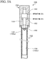
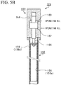
- FIGS. 5A and 5B are views showing the fuel injecting unit 126.
- the fuel pipe 152 is configured to have an inner pipe 156 and an outer pipe 158.
- the fuel gas is guided into the inside of the inner pipe 156, and the outer pipe 158 stows the inner pipe 156 inside thereof and forms a double pipe with the inner pipe 156.
- An outer diameter of the inner pipe 156 is slightly smaller than an inner diameter of the outer pipe 158, and the outer circumferential surface of the inner pipe 156 substantially entirely abuts on the inner circumferential surface of the outer pipe 158.
- a front end of the inner pipe 156 on the lower side in FIGS. 5A and 5B has an opening, and the inside of a main body 158a of the outer pipe 158 and the inside of a main body 156a of the inner pipe 156 communicate with each other via the opening.
- the outer pipe 158 communicates with the communication piping 148 shown in FIG. 3 , and the fuel gas is supplied to the outer pipe 158 from the communication piping 148.
- the fuel gas guided to the inside of the main body 158a of the outer pipe 158 flows into the inside of the main body 156a of the inner pipe 156 from the front end (lower end) of the inner pipe 156.
- the driving unit 154 includes two hydraulic chambers 160 and 162, and a hydraulic piston 164 functioning as a partition between the two hydraulic chambers 160 and 162.
- a shaft 166 is fixed to the hydraulic piston 164, and a base end (upper end) of the inner pipe 156 is fixed to a front end side of the shaft 166 on the lower side in FIGS. 5A and 5B .
- the driving unit 154 causes the inner pipe 156 to move in a vertical direction (that is, a stroke direction of the piston 112 in the cylinder 110, hereinafter, abbreviated to a stroke direction in some cases) in FIGS. 5A and 5B , and changes relative positions of the inner pipe 156 and the outer pipe 158.
- FIGS. 6A and 6B are sectional views of the inner pipe 156 and the outer pipe 158, and showing portions surrounded by dashed lines in FIGS. 5A and 5B which are rotated by 90 degrees in the counterclockwise direction.
- the right side is the bottom dead center side (one end side in the stroke direction) of the piston 112
- the left side is the top dead center side (the other end side in the stroke direction) of the piston 112.
- the inner pipe 156 has inner holes 174 penetrating through the main body 156a of the inner pipe 156 from the inside to the outside thereof
- the outer pipe 158 has outer holes 176 penetrating through the main body 158a of the outer pipe 158 from the inside to the outside thereof.
- a plurality of inner holes 174 and outer holes 176 are formed to be separated from one another in the stroke direction (rightward-leftward direction in FIGS. 6A and 6B ).
- the fuel gas flowing inside the inner pipe 156 is injected from the fuel pipe 152 through the inner hole 174 and the outer hole 176, and is joined to the active gas suctioned into the scavenging port 118.
- FIG. 7 is a first view showing a positional relationship between the inner holes 174 and the outer holes 176, and shows the external appearance in which the same positions in FIGS. 6A and 6B are disposed in the same orientation as in FIGS. 6A and 6B .
- the right side is the bottom dead center side (one end side in the stroke direction) of the piston 112
- the left side is the top dead center side (the other end side in the stroke direction) of the piston 112.
- a dashed line represents a line showing an outer edge of the inner pipe 156 stowed in the outer pipe 158.
- the plurality of outer holes 176 have a circular shape in the cross-sectional plane of which normal axis is perpendicular to a penetrating direction of the outer pipe 158 and have the same diameter, and the plurality of inner holes 174 have different lengths from each other in the stroke direction.
- the inner holes 174 formed on the top dead center side (left side in FIG. 7 ) of the piston 112 are longer in length in the stroke direction than the inner holes 174 formed on the bottom dead center side (right side in FIG. 7 ) of the piston 112.
- the inner hole 174 on the rightmost side (n-th hole from the left in FIG. 7 ) has the same shape as the outer hole 176 in the cross-sectional plane of which normal axis is perpendicular to the penetrating direction of the inner pipe 156.
- both ends of each first to (n-1)-th inner holes 174 from the left have a semicircular arc shape with the same diameter as that of the outer holes 176, and a straight line shape is formed between two semicircular arcs.
- the lengths of the portions of the straight line shapes in the stroke direction are different for each of the inner holes 174.
- a distance P between adjacent outer holes 176 is constant.
- a distance A from the center of the left semicircular arc, in FIG. 7 , of the inner hole 174 to the center of the corresponding outer hole 176 is constant, also for any inner hole 174 and the corresponding outer hole 176.
- B represents a distance from the center of the right semicircular arc, in FIG. 7 , of the inner hole 174 to the center of the outer hole 176.
- Numbers are assigned to reference signs (B 1 , B 2 , B 3 , ⁇ , B n-1 , B n ) representing the distances B in order from the left in FIG. 7 .
- B 1 ⁇ B 2 ⁇ B 3 ⁇ ⁇ ⁇ B n-1 ⁇ B n is obtained.
- FIG. 8 is a second view showing the positional relationship between the inner holes 174 and the outer holes 176.
- reference signs assigned to the inner holes 174 and the outer holes 176 are omitted, the inner holes 174 are represented by hatched portions and the outer holes 176 are represented by cross-hatched portions.
- the right side is the bottom dead center side (one end side in the stroke direction) of the piston 112
- the left side is the top dead center side (the other end side in the stroke direction) of the piston 112.
- d represents the inner diameter of the outer hole 176
- L represents the length of the inner hole 174
- numbers are assigned to reference signs in order from the left in FIG. 8 .
- the inner hole 174 has a length L shorter, by the inner diameter d of the outer hole 176, than an adjacent inner hole 174 on the left side in FIG. 8 .
- the distance P of the outer holes 176 is longer than a product of the inner diameter d and (n+1) obtained by adding 1 to the number n of the outer holes 176.
- FIGS. 9A to 9D are views showing a change in the relative positions of the inner pipe 156 and the outer pipe 158 stage by stage.
- the right side is the bottom dead center side (one end side in the stroke direction) of the piston 112
- the left side is the top dead center side (the other end side in the stroke direction) of the piston 112.
- the first inner hole 174 from the top dead center side (left side in FIGS. 9A to 9D ) of the piston 112 starts to overlap the outer hole 176, as shown in FIG. 9B .
- the first and second inner holes 174 from the top dead center side (left side in FIGS. 9A to 9D ) of the piston 112 overlaps the outer hole 176 so as to achieve a fully open state, and the third inner hole 174 starts to overlap the outer hole 176 as shown in FIG. 9C .
- the inner holes 174 and the outer holes 176 are sequentially opened from the top dead center side (left side in FIGS. 9A to 9D ) of the piston 112, and all of the inner holes 174 and the outer holes 176 overlap each other so as to achieve the fully open state. Then, the holes are sequentially closed from the bottom dead center side (right side in FIGS. 9A to 9D ) of the piston 112.
- an opening region which is positioned relatively on one end side (right side in FIGS. 9A to 9D ) in the stroke direction, of a portion in which the inner pipe 156 and the outer pipe 158 overlap each other, and is formed by the overlap between the inner holes 174 and the outer holes 176, is referred to as a small-flow-quantity opening region Os.
- an opening region which is positioned on the top dead center side (left side in FIGS. 9A to 9D ) of the piston 112 from the small-flow-quantity opening region Os, of a portion in which the inner pipe 156 and the outer pipe 158 overlap each other, is referred to as a large-flow-quantity opening region Ob.
- the small-flow-quantity opening region Os and the large-flow-quantity opening region Ob are regions having a predetermined size including the outer hole 176 in the outer pipe 158.
- the inner hole 174 and the outer hole 176 which form the large-flow-quantity opening region Ob are separated in the stroke direction from the inner hole 174 and the outer hole 176 which form the small-flow-quantity opening region Os.
- the inner hole 174 and the outer hole 176 which form the large-flow-quantity opening region Ob are positioned on the top dead center side (left side in FIGS. 9A to 9D ) of the piston 112 from the inner hole 174 and the outer hole 176 which form the small-flow-quantity opening region Os. Therefore, the large-flow-quantity opening region Ob is in a state in which the inner hole 174 and the outer hole 176 overlap each other for a longer time than the small-flow-quantity opening region Os.
- the inner hole 174 and the outer hole 176 overlap each other earlier than in the small-flow-quantity opening region Os, and the overlap between the inner hole 174 and the outer hole 176 is delayed before being cancelled.
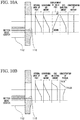
- FIGS. 10A and 10B are diagrams showing a relationship between a degree of opening of the scavenging port 118 and a concentration of mixture.
- the vertical direction represents the stroke direction of the piston 112
- the upper side corresponds to the top dead center side (the other end side in the stroke direction) of the piston 112
- the lower side corresponds to the bottom dead center side (the one end side in the stroke direction) of the piston 112.
- the scavenging port 118 has an opening area which changes depending on the position of the piston 112 as shown in the graph of the opening area of the port in FIGS. 10A and 10B .
- the scavenging port 118 starts to be opened, the scavenging port 118 starts to be opened from a portion thereof on the top dead center side of the piston 112, finally, to a portion thereof on the bottom dead center side.
- the scavenging port 118 starts to be closed, the scavenging port 118 starts to be closed from the portion thereof on the bottom dead center side of the piston 112, finally, to the portion thereof on the top dead center side.
- a scavenging air amount changes in proportion to an opening area of the port, as shown in the graph of the scavenging air amount in FIGS. 10A and 10B .
- an injection amount of the fuel gas is not proportional to the opening area of the port, as shown in the graph of the gas injection amount. Therefore, as shown in the graph of the concentration of mixture in FIG. 10B , the concentration of mixture of the fuel gas and the active gas from the scavenging port 118 is likely to be locally rich.
- the inner pipe 156 shifts in proportion to the opening area of the port.
- the inner holes 174 and the outer holes 176 are sequentially opened from the top dead center side of the piston 112 while the opening area of the scavenging port 118 increases as described above.
- the inner holes 174 and the outer holes 176 are sequentially closed from the bottom dead center side of the piston 112.
- the injection amount of the fuel gas increases and decreases in proportional to an amount of the active gas, as shown in the graph of the gas injection amount in FIG. 10A . Therefore, it is possible to maintain substantially a constant concentration of mixture of the fuel gas and the active gas flowing through the scavenging port 118.
- the large-flow-quantity opening region Ob positioned on the top dead center side is in the state in which the inner hole 174 and the outer hole 176 overlap each other for a longer time than the small-flow-quantity opening region Os positioned on the bottom dead center side. Therefore, the injection amount of the fuel gas is large from the large-flow-quantity opening region Ob on the top dead center side in which the opening time is long, of the scavenging port 118, and an even concentration of the mixture is obtained.
- the inner hole 174 and the outer hole 176 overlap each other earlier than in the small-flow-quantity opening region Os, and the overlap between the inner hole 174 and the outer hole 176 is delayed before being cancelled. Therefore, it is possible to inject the fuel gas by opening and closing the inner holes 174 and the outer holes 176 in the large-flow-quantity opening region Ob and the small-flow-quantity opening region Os at timings closer to the opening and closing of the scavenging port 118.
- FIGS. 11A and 11B are views showing inner holes 274 and outer holes 276 according to a first modification example.
- the inner hole 274 and the outer hole 276, which have a correspondence relationship have the same shape in the cross-sectional plane of witch normal axis is perpendicular to the penetrating direction of the inner pipe 156 and the outer pipe 158, and each has a rectangular shape.
- 11A and 11B are longer on the top dead center side than on the bottom dead center side, and the lengths of the inner holes 274 and the outer holes 276 in the rightward-leftward direction in FIGS. 11A and 11B (length in the stroke direction) are the same.
- the large-flow-quantity opening region Ob has the larger opening amount all the times than the small-flow-quantity opening region Os from start to end of the overlap between the inner holes 274 and the outer holes 276. Therefore, of the scavenging port 118, the amount of the fuel gas, which is injected on the top dead center side on which a relatively large quantity of the active gas flows, increases, and the amount of the fuel gas, which is injected on the bottom dead center side on which a relatively small quantity of the active gas flows, decreases. Thus, it is possible to obtain the even concentration of the mixture.
- FIGS. 12A and 12B are views showing inner holes 374 and outer holes 376 according to a second modification example. As shown in FIGS. 12A and 12B , in the second modification example, four circular inner holes 374 are provided with respect to one circular outer hole 376. In addition, of a plurality of outer holes 376, the outer hole on the top dead center side has the largest diameter, and the diameters of the outer holes gradually decrease as the outer holes are close to the bottom dead center side.
- the inner holes 374 have diameters which gradually increases from that of the inner hole closer to the corresponding outer hole 376.
- an inner diameter of the outer hole 376 is larger on the top dead center side, and inner diameters of the inner holes 374 that overlap the outer hole 376 sequentially increase as the holes are close to the top dead center. Therefore, as the inner pipe 156 moves to the bottom dead center side, the large-flow-quantity opening region Ob on the top dead center side has the opening area larger than that of the small-flow-quantity opening region Os stage by stage. As the inner pipe 156 returns to move to the top dead center side, the opening area on the top dead center side decreases stage by stage.
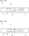
- FIGS. 13A and 13B are views showing an inner hole 474 and an outer hole 476 according to a third modification example. As shown in FIGS. 13A and 13B , in the third modification example, one inner hole 474 and one outer hole 476 are formed.
- the outer hole 476 has a width (width in a direction perpendicular to the stroke direction) in the vertical direction in FIGS. 13A and 13B , which gradually decreases from the top dead center side to the bottom dead center side.
- the inner hole 474 has a width in the vertical direction in FIGS. 13A and 13B , which is substantially constant from the top dead center side toward the bottom dead center side.
- the large-flow-quantity opening region Ob has the larger opening amount than the small-flow-quantity opening region Os.
- the large-flow-quantity opening region Ob is in the state in which the inner hole 474 and the outer hole 476 overlap each other for a longer time than the small-flow-quantity opening region Os, and thus the even concentration of the mixture is obtained.
- the inner hole 474 and the outer hole 476 overlap each other earlier than in the small-flow-quantity opening region Os, and the overlap between the inner hole 474 and the outer hole 476 is delayed before being cancelled. Therefore, it is possible to open and close the inner hole 474 and the outer hole 476 in the large-flow-quantity opening region Ob and the small-flow-quantity opening region Os at timings closer to the opening and closing of the scavenging port 118.
- FIGS. 14A and 14B are views showing a fuel injecting unit 526 according to a fourth modification example.
- the fuel injecting unit 126 of the embodiment described above stops the injection of the fuel gas by cancelling the overlap between the inner holes 174 of the inner pipe 156 and the outer holes 176 of the outer pipe 158.
- the injection of the fuel gas is stopped with a valve body 572, in addition to the cancel of the overlap between the inner holes 174 of the inner pipe 156 and the outer holes 176 of the outer pipe 158.
- the fuel injecting unit 526 is provided with a gas chamber 568, which communicates with the communication piping 148 shown in FIG. 3 , between the hydraulic chamber 162 and the inner pipe 156, and the fuel gas is supplied from the communication piping 148.
- the gas chamber 568 communicates with the inside of the main body 158a of the outer pipe 158.
- the shaft 166 is provided with the valve body 572 formed in a position in which the gas chamber 568 is disposed, and the valve body 572 opens and closes a communication portion between the gas chamber 568 and the outer pipe 158 in response to the movement of the shaft 166.
- the base end side (top side) of the inner pipe 156 has a taper surface 556b, and the outer diameter of the taper surface 556b is smaller than the inner diameter of the outer pipe 158.
- the taper surface 556b is provided with a communication hole 556c, and the inside of the main body 158a of the outer pipe 158 communicates with the inside of the main body 156a of the inner pipe 156 via the communication hole 556c.
- the spring member 570 is disposed in the gas chamber 568.
- a bias force is applied to the valve body 572 in a direction in which the valve body 572 is closed, and thereby the movement of the shaft 166 is assisted by the hydraulic pressure.
- the injection of the fuel gas is stopped with the valve body 572, in addition to the cancel of the overlap between the inner holes 174 of the inner pipe 156 and the outer holes 176 of the outer pipe 158. As a result, it is possible to prevent the fuel gas from leaking from the fuel injecting unit 526.
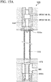
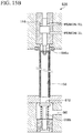
- FIGS. 15A and 15B are views showing a fuel injecting unit 626 according to a fifth modification example.
- the gas chamber 568 is disposed on the same side as the hydraulic chambers 160 and 162 with respect to the fuel pipe 152, and the inner pipe 156 and the valve body 572 move at the same time with the one shaft 166.
- a shaft 666a fixed to the inner pipe 156 and the hydraulic piston 164 and a shaft 666b provided with a valve body 672 are separately provided.
- the shaft 666b which is independent of the hydraulic piston 164, moves in the vertical direction in FIGS. 15A and 15B by a hydraulic mechanism (not shown), and opens or closes the valve body 672.
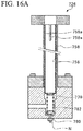
- FIGS. 16A and 16B are views showing a fuel injecting unit 726 according to a sixth modification example.
- the fuel injecting unit 126 of the embodiment described above causes the inner pipe 156 to move with the hydraulic pressure.
- no hydraulic mechanism is installed.
- a projecting portion 758a which projects inwardly, is formed at the end portion of an outer pipe 758 on the upper side (upward in the stroke direction) in FIGS. 16A and 16B .
- the projecting portion 758a is disposed on the upper side in FIGS. 16A and 16B from the portion of the outer pipe 758, in which the inner pipe 756 is stowed.
- a part of the projecting portion 758a extends to the inner pipe 756 side, and is fit into a guide groove 756a formed in the inside of the inner pipe 756 on the upper side in FIGS. 16A and 16B .
- the projecting portion 758a and the guide groove 756a regulate the movement of the inner pipe 756 which rotates with respect to the outer pipe 758; however, the inner pipe 756 can move in the vertical direction in FIGS. 16A and 16B .
- FIGS. 16A and 16B An end portion of the inner pipe 756 on the lower side is closed in FIGS. 16A and 16B , and one end of a spring member 770 (bias member) is fixed to the inner pipe 756 on the outer side.
- the other end of the spring member 770 is fixed to an adjustment member 780, the position of the adjustment member 780 is adjusted by fastening of a nut N, and thereby a position of the other end of the spring member 770 is adjusted in the stroke direction (direction of elastic deformation of the spring member 770).
- the spring member 770 applies the bias force of pressing (biasing) the inner pipe 756 in a direction (here, the upper side in FIGS. 16A and 16B ) parallel to a changing direction of a relative position with respect to the outer pipe 758.
- a spring chamber 782 in which the spring member 770 is disposed, communicates with the scavenging chamber 120, and the inner pipe 756 is pressed upward in FIGS. 16A and 16B with the pressure of the compressed active gas.
- the fuel gas is supplied to the inside of the inner pipe 756, and the inner pipe 756 is pressed downward in FIGS. 16A and 16B with the pressure of the fuel gas.
- the fuel injecting unit 726 does not need to be provided with the hydraulic mechanism, and thus it is possible to change the relative positions of the inner pipe 756 and the outer pipe 758 with the pressure of the fuel gas such that it is possible to reduce the costs.
- the case where the inner pipes 156 and 756 are caused to move such that the relative positions of the inner pipes 156 and 756 and the outer pipes 158 and 758 change is described above.
- the outer pipes 158 and 758 may be caused to move such that the relative positions of the inner pipes 156 and 756 and the outer pipes 158 and 758 change.
- the driving unit 154 causes the inner pipes 156 and 756 to move in the stroke direction.
- the inner pipes 156 and 756 or the outer pipes 158 and 758 may be caused to rotate in a direction other than the stroke direction, for example, in the circumferential direction of the inner pipes 156 and 756.
- by moving the inner pipes 156 and 756 or the outer pipes 158 and 758 in the stroke direction it is possible to simplify the structure and to reduce the costs.
- the scavenging port has the degree of opening that gradually increases in response to the movement of the piston to the bottom dead center side in the stroke direction, and then the degree of the opening is gradually decreases when the piston returns from the bottom dead center side to the top dead center side.
- the flow quantity of the active gas suctioned in the cylinder from the scavenging port changes while the scavenging port is opened once depending on the change in the degree of the opening of the scavenging port.
- Patent Document 1 described above when fuel gas is injected with substantially a constant injection pressure during the opening of the scavenging port once, the mixture of the fuel gas and the active gas is likely to be locally lean or rich.
- the uniflow scavenging two-cycle engine that is capable of achieving the evenness of the concentration of the fuel gas and the active gas which are suctioned while the scavenging port is opened once.
- a uniflow scavenging two-cycle engine including a cylinder in which a combustion chamber is formed, a piston that slides in the cylinder, a scavenging space which surrounds one end side of the cylinder in the stroke direction of the piston and to which compressed active gas is guided, a scavenging port that is provided in a portion positioned in the scavenging space in the cylinder, and that suctions active gas in the combustion chamber from the scavenging space in response to the sliding motion of the piston, a fuel injection opening that is provided on an outer side of the cylinder in a radial direction from the scavenging port injects fuel gas to active gas suctioned in the scavenging port, and an opening-closing mechanism that opens and closes the fuel injection opening depending on a pressure difference between a first position at which a pressure change is produced in proportion to the degree of opening of the scavenging port and a second position at which the pressure change is
- the first position may be positioned in the scavenging port.
- the second position may be positioned to be farther separated from the scavenging port than the fuel injection opening.
- the uniflow scavenging two-cycle engine may further include an inner pipe which has an inner hole penetrating between an inside and an outside thereof and through which fuel gas is guided to the inside, an outer pipe which has an outer hole penetrating between an inside and an outside thereof and stows the inner pipe in the inside thereof so as to form a double pipe with the inner pipe.
- the fuel injection opening may be formed by overlapping the inner hole and the outer hole, and an opening-closing mechanism may change relative positions of the inner pipe and the outer pipe with a pressing force due to the pressure difference, thereby changing an opening amount of the fuel injection opening.
- the inner pipe When differential pressure between the second position and the first position increases, the inner pipe may be pressed to one end side in the stroke direction. When the differential pressure decreases, the inner pipe may be pressed to the other end side in the stroke direction.
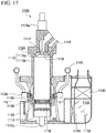
- FIG. 17 is a view showing an entire configuration of a uniflow scavenging two-cycle engine 1100.
- the uniflow scavenging two-cycle engine 1100 of the embodiment is used in a ship or the like.
- the uniflow scavenging two-cycle engine 1100 is configured to include a cylinder 1110, a piston 1112, an exhaust port 1114, an exhaust valve 1116, a scavenging port 1118, a scavenging reservoir (scavenging space) 1120, a scavenging chamber 1122 (scavenging space), a combustion chamber 1124, fuel pipes 1126, and an opening-closing mechanism 1128.
- the exhaust port 1114 is an opening provided in a cylinder head 1110a positioned above the top dead center of the piston 1112, and is opened and closed to discharge exhaust gas produced after combustion in the cylinder 1110.
- the exhaust valve 1116 slides vertically at a predetermined timing by an exhaust valve driving device 1116a and opens or closes the exhaust port 1114. When the exhaust port 1114 is opened, exhaust gas is discharged from the cylinder 1110 via the exhaust port 1114.
- the scavenging port 1118 is a hole penetrating from an inner circumferential surface (inner circumferential surface of a cylinder liner 1110b) to an outer circumferential surface of the cylinder 1110 on the lower end side, and a plurality of scavenging ports are provided all around the cylinder 1110.
- the scavenging ports 1118 suction active gas in the cylinder 1110 in response to a sliding motion of the piston 1112.
- the active gas contains an oxidizing agent such as oxygen or ozone, or a mixture thereof (for example, air).
- the active gas for example, air
- a blower (not shown) is sealed in the scavenging reservoir 1120, and the active gas is cooled by the cooler 1130.
- the compressed and cooled active gas is rectified by a current plate 1132 disposed in the scavenging reservoir 1120, and then moisture is removed by a drain separator 1134.
- the scavenging chamber 1122 communicates with the scavenging reservoir 1120 and surrounds one end side (lower side in FIG. 17 ) of the cylinder 1110 in the stroke direction of the piston 1112 (hereinafter, simply abbreviated to a "stroke direction" in some cases), and active gas subjected to compression, cooling, and removal of moisture is guided thereto.
- the scavenging reservoir 1120 and the scavenging chamber 1122 configure the scavenging space.
- the scavenging space is a space to which the compressed active gas is guided and which surrounds the one end side (lower side in FIG. 17 ) of the cylinder 1110 in the stroke direction of the piston 1112.
- the scavenging reservoir 1120 and the scavenging chamber 1122 are described; however the scavenging space is not limited to the scavenging reservoir 1120 and the scavenging chamber 1122 as long as the scavenging space is a space to which the compressed active gas is guided and which surrounds the one end side of the cylinder 1110 in the stroke direction of the piston 1112.
- the scavenging port 1118 is provided in a portion of the cylinder 1110 (cylinder liner 1110b) positioned in the scavenging chamber 1122, and suctions active gas from the scavenging chamber 1122 into the cylinder 1110 due to the differential pressure between the scavenging chamber 1122 and the cylinder 1110.
- the active gas suctioned in the cylinder 1110 is guided by the piston 1112 to the combustion chamber 1124 in response to the sliding motion of the piston 1112.
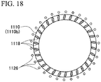
- FIG. 18 is a sectional view taken along line II-II in FIG. 17 .
- a cross-sectional plane of the fuel pipe 1126 is shown in a simplified manner, and an internal configuration of the fuel pipe 1126 will be described below in detail.
- the fuel pipe 1126 is provided on an outer side of the cylinder 1110 (cylinder liner 1110b) in the radial direction from the scavenging port 1118.
- the fuel pipe 1126 is disposed on the outer side of the outer surface of the cylinder 1110 in the radial direction between adjacent scavenging ports 1118, and thus the fuel pipe 1126 is unlikely to interfere with flowing of the active gas.
- the fuel pipe 1126 is provided with annular pipe 1136 on the exhaust port 1114 side (upper side in FIG. 17 ).
- the annular pipe 1136 is a pipe that annularly surrounding the outer side of the cylinder 1110 in the radial direction, along the circumferential direction of the cylinder 1110 and communicates with the fuel pipe 1126.
- the fuel gas is guided to the annular pipe 1136 via the fuel injecting valve 1138 from a fuel tank 1140 in which the fuel gas is stored.
- the annular pipe 1136 communicates with the fuel pipes 1126, respectively, the fuel injection opening, which will be described below, is formed in the fuel pipe 1126, the fuel gas flowing into the fuel pipe 1126 via the annular pipe 1136 from the fuel tank 1140 is injected into the active gas suctioned to the scavenging port 1118 from the fuel pipe 1126.
- the fuel gas and the active gas are suctioned in the cylinder 1110 through the scavenging port 1118 and are guided to the combustion chamber 1124.
- a pilot injection valve 1142 is provided in the cylinder head 1110a.
- An appropriate amount of fuel oil is injected from the pilot injection valve 1142 at a predetermined time point in an engine cycle.
- the fuel oil is vaporized with the heat in the combustion chamber 1124 and becomes the fuel gas.
- the fuel gas obtained by vaporization of the fuel oil spontaneously ignites, is combusted in a short time, and the temperature of the combustion chamber 1124 rises to be very high.
- the piston 1112 reciprocates using expansion pressure produced from the combustion of the fuel gas mainly guided from the scavenging port 1118.
- the fuel gas is generated, for example, by gasifying liquefied natural gas (LNG).
- LNG gasifying liquefied natural gas
- the fuel gas is not limited to the LNG, and, for example, gas generated by gasifying liquefied petroleum gas (LPG), gas oil, heavy oil, or the like can be applied to the fuel gas.
- LPG gasifying liquefied petroleum gas
- LPG gas oil, heavy oil, or the like
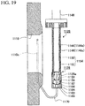
- FIG. 19 is an enlarged view of a portion in a dashed line in FIG. 17 .
- the fuel pipe 1126 is configured to have an inner pipe 1144 and an outer pipe 1146.
- the inner pipe 1144 communicates with the annular pipe 1136 via a communication passage 1148 on the upper side in FIG. 19 , and the fuel gas is guided to the inside of the main body 1144a of the inner pipe 1144 from the annular pipe 1136.
- the outer pipe 1146 stows the inner pipe 1144 inside the main body 1146a and forms a double pipe with the inner pipe 1144.
- the inner pipe 1144 has inner holes 1150 communicating from the inside to the outside of the main body 1144a, and the outer pipe 1146 has outer holes 1152 communicating from the inside to the outside of the main body 1146a.
- the inner pipe 1144 has a front end on the lower side in FIG. 19 , which is closed, and the fuel gas guided to the inside of the main body 1144a of the inner pipe 1144 remains inside the main body 1144a until the inner holes 1150 and the outer holes 1152 overlap each other.
- the fuel gas is injected to the outside of the fuel pipe 1126 through the inner holes 1150 and the outer holes 1152.
- the inner holes 1150 and the outer holes 1152 overlap each other, and thereby the fuel injection opening 1154 that injects the fuel gas into the active gas suctioned in the scavenging port 1118 is formed.
- the fuel injection opening 1154 formed in the fuel pipe 1126 is also provided on the outer side of the cylinder 1110 in the radial direction from the scavenging port 1118.
- the opening-closing mechanism 1128 changes the relative positions of the inner pipe 1144 and the outer pipe 1146 in the stroke direction (vertical direction in FIG. 19 ) of the piston 1112, the inner hole 1150 and the outer hole 1152 are caused to overlap each other, and thereby the fuel injection opening 1154 is opened. The overlap is cancelled, and thereby the fuel injection opening 1154 is closed.
- the opening-closing mechanism 1128 has a main body 1128a fixed to the front end side (lower side in FIG. 19 , and the bottom dead center side of the piston 1112) of the outer pipe 1146.
- the main body 1128a is provided with a spring member 1156 in the inside thereof.
- One end of the spring member 1156 abuts on the front end portion of the inner pipe 1144, and the other end thereof abuts on a partition wall 1158 formed in the main body 1128a.
- the spring member 1156 applies a bias force of pressing the inner pipe 1144 to the top dead center side of the piston 1112.
- two pressure chambers 1160 and 1162 are provided inside the main body 1128a on the to bottom dead center side from the spring member 1156.
- the two pressure chambers 1160 and 1162 are provided to be continuous in the stroke direction of the piston 1112, and are partitioned with a partition member 1164 that is elastically deformed due to the pressure difference between the two pressure chambers 1160 and 1162.
- One end of a shaft 1166 is fixed to the partition member 1164, and the other end of the shaft 1166 penetrates the partition wall 1158, projects to the spring member 1156 side, and faces the front end portion of the inner pipe 1144.
- the other end of the shaft 1166 presses the front end of the inner pipe 1144 due to the pressure difference between the two pressure chambers 1160 and 1162 in response to elastic deformation of the partition member 1164, and the inner pipe 1144 is pressed to the top dead center side.
- the pressure chamber 1160 on the bottom dead center side is provided with a spring member 1168 between the partition member 1164 and the main body 1128a, and the spring member 1168 applies a bias force of pressing the partition member 1164 to the top dead center side, thereby supporting the partition member 1164.
- Communication piping 1170 is connected to the pressure chamber 1160 on the bottom dead center side.
- the cylinder 1110 is provided with a through-hole 1110c formed to penetrate through the cylinder 1110 from the outer circumferential surface to the scavenging port 1118.
- the communication piping 1170 and the through-hole 1110c are connected, and the inside (first position) of the scavenging port 1118 communicates with the pressure chamber 1160 via the communication piping 1170 and the through-hole 1110c.
- piping (not shown) is connected to the pressure chamber 1162 on the top dead center side, the pressure chamber 1162 communicates, via the piping, with a position farther separated from the scavenging port 1118 than the fuel injection opening 1154, such as a position (second position) of the scavenging reservoir 1120, at which the active gas less flows.
- the second position has a small pressure change of static pressure to the extent that the active gas less flows than at the first position.
- FIG. 20 is a view showing the fuel pipe 1126 and the opening-closing mechanism 1128 in FIG. 19 .
- the plurality of inner holes 1150 and outer holes 1152 are provided to be separated from one another in the stroke direction, and are provided at an equal interval in the stroke direction.
- the inner holes 1150 and the outer holes 1152 have the same shape in the cross-sectional plane of which normal axis is perpendicular to the penetrating direction.
- a movable distance of the inner pipe 1144 in the stroke direction is a length represented by reference sign M in FIG. 20 .
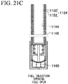
- FIGS. 21A to 21C are views showing opening and closing of the fuel injection opening 1154. As shown in FIG. 21A , when the inner pipe 1144 is positioned to be closest to the top dead center side, the inner holes 1150 and the outer holes 1152 do not overlap each other, and the fuel injection opening 1154 is completely closed.
- the scavenging port 1118 starts to be opened, and the active gas starts to be suctioned from the scavenging port 1118 into the cylinder 1110, dynamic pressure in the scavenging port 1118 increases and the static pressure therein decreases.
- pressure of the pressure chamber 1160 starts to decrease, and the inner pipe 1144 moves to the bottom dead center side as shown in FIG. 21B .
- the inner holes 1150 and the outer holes 1152 partially overlap each other, and a part of the fuel injection opening 1154 is opened.
- the scavenging port 1118 when the scavenging port 1118 is fully opened, a flow rate of the active gas suctioned from the scavenging port 1118 into the cylinder 1110 increases, the dynamic pressure in the scavenging port 1118 increases, the static pressure therein remarkably decreases, and the pressure of the pressure chamber 1160 further decreases.
- the inner pipe 1144 moves to be closest to the bottom dead center side and the inner holes 1150 and the outer holes 1152 completely overlap each other. In other words, the fuel injection opening 1154 is fully opened.
- FIGS. 22A and 22B are diagrams showing a relationship between a degree of opening of the scavenging port 1118 and a concentration of mixture.
- the vertical direction represents the stroke direction of the piston 1112
- the upper side corresponds to the top dead center side of the piston 1112
- the lower side corresponds to the bottom dead center side of the piston 1112.
- the scavenging port 1118 has an opening area which changes depending on the position of the piston 1112 as shown in the graph of the opening area of the port in FIGS. 22A and 22B .
- the scavenging port 1118 starts to be opened from a portion thereof on the top dead center side of the piston 1112, finally, to a portion thereof on the bottom dead center side.
- the scavenging port 1118 starts to be closed from the portion thereof on the bottom dead center side of the piston 1112, finally, to the portion thereof on the top dead center side.
- a scavenging air amount changes in proportion to an opening area of the port, as shown in the graph of the scavenging air amount in FIGS. 22A and 22B .
- an injection amount of the fuel gas is not proportional to the opening area of the port, as shown in the graph of the gas injection amount. Therefore, as shown in the graph of the concentration of mixture in FIG. 22B , the concentration of mixture of the fuel gas and the active gas from the scavenging port 1118 is likely to be locally rich.
- the opening-closing mechanism 1128 is provided to cause the relative position of the inner pipe 1144 to automatically shift with respect to the outer pipe 1146 depending on the pressure difference ⁇ P, and also changes the opening area of the fuel injection opening 1154 shown in the graph of the opening area of injection opening in FIG. 22A , depending on the opening area of the scavenging port 1118.
- the case where the pressure difference between the first position and the second position is changed into the pressing force, and the opening-closing mechanism 1128 opens or closes the fuel injection opening 1154 is described above; however, for example, the pressure difference between the first position and the second position may be acquired as an electric signal, and the opening-closing mechanism 1128 may open or close the fuel injection opening 1154 with an actuator depending on the pressure difference between the first position and the second position.
- the first position is positioned in the scavenging port 1118 ; however, the first position may be positioned in any portion other than the scavenging port 1118, as long as the pressure change is produced at the position depending on the degree of the opening of the scavenging port 1118.
- the first position is disposed in the scavenging port 1118, and thereby the pressure change depending on the degree of the opening of the scavenging port 1118 is reflected to the degree of the opening of the fuel injection opening 1154 with high accuracy.
- the second position is positioned to be farther separated from the scavenging port 1118 than from the fuel injection opening 1154; however, the second position may be positioned in any position, as long as the pressure change is smaller than at the first position.
- the second position is positioned to be farther separated from the scavenging port 1118, such as the scavenging reservoir 1120, than from the fuel injection opening 1154, the second position is unlikely to receive an effect of the flow of the active gas that is suctioned in the scavenging port 1118 and the pressure change is reduced such that it is possible to appropriately perform the opening and closing of the fuel injection opening 1154.
- the double pipe configured to have the inner pipe 1144 and the outer pipe 1146
- the fuel injection opening 1154 is formed in proportion to the overlap between the inner holes 1150 and the outer holes 1152
- the double pipe is not included in the necessary configuration, and the fuel injection opening 1154 may be opened or closed by another opening-closing mechanism depending on the pressure difference between the first position and the second position.
- the double pipe is configured to have the inner pipe 1144 and the outer pipe 1146, and thereby it is possible to open or close the fuel injection opening 1154 with a simple mechanism.
- the inner pipe 1144 when the differential pressure between the scavenging reservoir 1120 (second position) and the scavenging port 1118 (first position) increases, the inner pipe 1144 is pressed to the one end side (bottom dead center side) in the stroke direction.
- the differential pressure decreases, of the inner pipe 1144 is pressed to the other end side (top dead center side) in the stroke direction is described above.
- the inner pipe 1144 when the differential pressure between the scavenging reservoir 1120 (second position) and the scavenging port 1118 (first position) increases, the inner pipe 1144 may be pressed to the top dead center side in the stroke direction. In this case, when the differential pressure decreases, the inner pipe 1144 is pressed to the bottom dead center side in the stroke direction.
- a portion in which the outer hole 1152 and the inner hole 1150 start to overlap each other is the top dead center side of one outer hole 1152. Since a portion the scavenging port 1118, in which the scavenging port starts to open, is also the top dead center side, it is possible to start the injection of the fuel gas from the side close to the active gas that flows in the scavenging port 1118 that starts to be opened such that an effect is achieved in that the fuel gas is less locally rich or lean.
Landscapes
- Engineering & Computer Science (AREA)
- Chemical & Material Sciences (AREA)
- Combustion & Propulsion (AREA)
- Mechanical Engineering (AREA)
- General Engineering & Computer Science (AREA)
- Chemical Kinetics & Catalysis (AREA)
- General Chemical & Material Sciences (AREA)
- Oil, Petroleum & Natural Gas (AREA)
- Fuel-Injection Apparatus (AREA)
Abstract
Description
- The present disclosure relates to a uniflow scavenging two-cycle engine that suctions fuel gas along with active gas from a scavenging port into a cylinder.
- Priority is claimed on Japanese Patent Application No.
2014-224455 2014-224456, filed on November 4, 2014 - A uniflow scavenging two-cycle engine that is also used as an engine in a ship is provided with a scavenging port on one end side and an exhaust port on the other end side of a piston in a stroke direction in a cylinder. When active gas is suctioned from the scavenging port to a combustion chamber in an intake (feeding) stroke, exhaust gas produced in combustion behavior is pushed and is exhausted from the exhaust port with the suctioned active gas.
- In such a uniflow scavenging two-cycle engine, technology of supplying fuel gas from the scavenging port side into the cylinder without directly injecting, into the combustion chamber, the fuel gas, which is a gaseous fuel, as a fuel is developed. For example, in an engine disclosed in
Patent Document 1, an annular chamber that extends in a circumferential direction of a cylinder is formed on an upper side of a scavenging port in an outer wall of the cylinder. In addition, a nozzle pipe penetrates an inner wall of the scavenging port from the chamber and extends to the inside of the scavenging port. When a control valve that communicates with the chamber is opened, fuel gas is supplied into the chamber through the control valve and the fuel gas is injected into the scavenging port through the nozzle pipe from the chamber. - [Patent Document 1] Japanese Patent (Granted) Application No.
3908855 - In a configuration disclosed in
Patent Document 1, the control valve is closed, and thereby injection of the fuel gas is stopped. However, the fuel gas remaining in the chamber or the nozzle pipe is likely to be injected through the scavenging port after the control valve is closed. In other words, there is an occurrence of delay from the time when the control valve is closed to the time when the injection of the fuel gas is actually and completely stopped. - In consideration of such a problem, an object of the present disclosure is to provide a uniflow scavenging two-cycle engine that is capable of rapidly stopping injection of fuel gas.
- A first aspect of a uniflow scavenging two-cycle engine of the present disclosure includes a cylinder in which a combustion chamber is formed; a piston that slides in the cylinder; a scavenging port that is provided one end side of the piston in a stroke direction in the cylinder and suctions active gas in the combustion chamber in response to a sliding motion of the piston; and a fuel injecting unit that is provided on an outer side of the cylinder in a radial direction from the scavenging port and injects fuel gas into the active gas which is suctioned into the scavenging port. Furthermore, the fuel injecting unit includes an inner pipe which has an inner hole penetrating between an inside and an outside thereof and through which fuel gas is guided to the inside, an outer pipe which has an outer hole penetrating between an inside and an outside thereof and stows the inner pipe in the inside thereof so as to form a double pipe with the inner pipe, and a driving unit which changes relative positions of the inner pipe and the outer pipe and changes an opening amount as an area of an overlap between the inner hole and the outer hole.
- According to the uniflow scavenging two-cycle engine of the present disclosure, it is possible to rapidly stop the injection of the fuel gas.
-
-
FIG. 1 is a view showing an entire configuration of a uniflow scavenging two-cycle engine. -
FIG. 2 is a view showing a configuration in the vicinity of a scavenging port inFIG. 1 . -
FIG. 3 is a view showing a gas injecting valve. -
FIG. 4 is a sectional view taken along line IV-IV inFIG. 2 . -
FIG. 5A is a view showing a fuel injecting unit. -
FIG. 5B is a view showing the fuel injecting unit. -
FIG. 6A is a sectional view of an inner pipe and an outer pipe. -
FIG. 6B is a sectional view of the inner pipe and the outer pipe. -
FIG. 7 is a first view showing a positional relationship between inner holes and outer holes. -
FIG. 8 is a second view showing the positional relationship between the inner holes and the outer holes. -
FIG. 9A is a view showing a change in relative positions of the inner holes and the outer holes stage by stage. -
FIG. 9B is a view showing the change in the relative positions of the inner holes and the outer holes stage by stage. -
FIG. 9C is a view showing the change in the relative positions of the inner holes and the outer holes stage by stage. -
FIG. 9D is a view showing the change in the relative positions of the inner holes and the outer holes stage by stage. -
FIG. 10A is a diagram showing a relationship between a concentration of mixture and a degree of opening of the scavenging port according to the present disclosure. -
FIG. 10B is a diagram showing a relationship between a concentration of mixture and a degree of opening of the scavenging port according to a comparative example. -
FIG. 11A is a view showing inner holes and outer holes according to a first modification example. -
FIG. 11B is a view showing the inner holes and the outer holes according to the first modification example. -
FIG. 12A is a view showing inner holes and outer holes according to a second modification example. -
FIG. 12B is a view showing the inner holes and the outer holes according to the second modification example. -
FIG. 13A is a view showing inner holes and outer holes according to a third modification example. -
FIG. 13B is a view showing the inner holes and the outer holes according to the third modification example. -
FIG. 14A is a view showing a fuel injecting unit according to a fourth modification example. -
FIG. 14B is a view showing inner holes and outer holes according to the fourth modification example. -
FIG. 15A is a view showing a fuel injecting unit according to a fifth modification example. -
FIG. 15B is a view showing inner holes and outer holes according to the fifth modification example. -
FIG. 16A is a view showing a fuel injecting unit according to a sixth modification example. -
FIG. 16B is a view showing inner holes and outer holes according to the sixth modification example. -
FIG. 17 is a view showing another entire configuration of a uniflow scavenging two-cycle engine. -
FIG. 18 is a sectional view taken along line II-II inFIG. 17 . -
Fig. 19 is an enlarged view of a portion in a dashed line inFIG. 17 . -
FIG. 20 is a view showing a fuel pipe and an opening-closing mechanism inFIG. 19 . -
FIG. 21A is a view showing opening and closing of a fuel injection opening. -
FIG. 21B is a view showing opening and closing of the fuel injection opening. -
FIG. 21C is a view showing opening and closing of the fuel injection opening. -
FIG. 22A is a diagram showing a relationship between a concentration of mixture and a degree of opening of the scavenging port according to the present disclosure. -
FIG. 22B is a diagram showing a relationship between a concentration of mixture and a degree of opening of the scavenging port according to a comparative example. - Hereinafter, a preferred embodiment according to the present disclosure will be described with reference to the accompanying figures. The dimensions, the materials, the specific numbers other than the dimensions and the materials, or the like is provided only as an example for easy understanding of the disclosure, and the disclosure is not limited thereto except for a case where particular description is provided. Note that, in the present specification and the figures, an element having substantially the same function and configuration is assigned with the same reference sign and a repeated description thereof is omitted, and illustration of an element without a direct relationship with the present disclosure is omitted in the figures.
-
FIG. 1 is a view showing an entire configuration of a uniflow scavenging two-cycle engine 100. The uniflow scavenging two-cycle engine 100 of the embodiment is used in a ship or the like. Specifically, the uniflow scavenging two-cycle engine 100 is configured to include acylinder 110, apiston 112, anexhaust port 114, anexhaust valve 116, a scavengingport 118, a scavengingchamber 120, agas supply pipe 122, agas injecting valve 124, and afuel injecting unit 126. - In the uniflow scavenging two-
cycle engine 100, exhaust, intake, compression, and combustion are performed during two strokes of an ascending stroke and a descending stroke of thepiston 112 and thepiston 112 slides in thecylinder 110. One end of apiston rod 112a is fixed to thepiston 112. In addition, a crosshead (not shown) is connected to the other end of thepiston rod 112a, and the crosshead reciprocates along with thepiston 112. When the crosshead reciprocates in response to the reciprocating of thepiston 112, a crankshaft (not shown) rotates by interlocking with the reciprocating of the crosshead. - The
exhaust port 114 is an opening provided in acylinder head 110a positioned above top dead center of thepiston 112, and is opened and closed to discharge exhaust gas produced after combustion in thecombustion chamber 128. Theexhaust valve 116 slides vertically at a predetermined timing by an exhaust valve driving device 116a and opens and closes theexhaust port 114. When theexhaust port 114 is opened, exhaust gas is discharged from thecylinder 110 via theexhaust port 114. - The scavenging
port 118 is a hole penetrating from an inner circumferential surface (inner circumferential surface of acylinder liner 110b) to an outer circumferential surface of thecylinder 110 on the lower end side, and a plurality of scavenging ports are provided all around the circumference of thecylinder 110. The scavengingports 118 suction active gas in thecylinder 110 in response to a sliding motion of thepiston 112. The active gas contains an oxidizing agent such as oxygen or ozone, or a mixture thereof (for example, air). -
FIG. 2 is a view showing the vicinity of the scavengingport 118 inFIG. 1 . As shown inFIG. 2 , the scavengingport 118 is provided in a region positioned in the scavengingchamber 120 in thecylinder 110. Active gas (for example, air) compressed by a blower (not shown) is guided into the scavengingchamber 120. - Therefore, when the scavenging
port 118 is opened in response to the sliding motion of thepiston 112, the active gas is suctioned from the scavengingchamber 120 through the scavengingport 118 into thecylinder 110 due to differential pressure between the scavengingchamber 120 and thecylinder 110. The active gas suctioned in thecylinder 110 is guided by thepiston 112 to thecombustion chamber 128. - The
gas supply pipe 122, through which a fuel tank (not shown), in which fuel gas is stored, and thegas injecting valve 124, guides the fuel gas from the fuel tank to thegas injecting valve 124. -
FIG. 3 is a view showing thegas injecting valve 124. As shown inFIG. 3 , ahydraulic piston 130 is disposed inside amain body 124a of thegas injecting valve 124, and thehydraulic piston 130 functions as a partition between ahydraulic chamber 132 and aspring chamber 134 which are formed inside themain body 124a. Thehydraulic piston 130 is able to slide on thehydraulic chamber 132 side and on thespring chamber 134 side inside themain body 124a. - The
hydraulic chamber 132 communicates with an operatingoil pipe 136 and is filled with operating oil supplied from the operatingoil pipe 136. Thehydraulic piston 130 is pressed upward inFIG. 3 by the operating oil in thehydraulic chamber 132. - In addition, a
spring member 138 is disposed in thespring chamber 134, and thespring member 138 abuts on thehydraulic piston 130 on thespring chamber 134 side. A bias force of thespring member 138 is applied to thehydraulic piston 130 in an orientation against a pressing force produced by the operating oil. - Hence, when the operating oil supplied to the
hydraulic chamber 132 has high hydraulic pressure, thehydraulic piston 130 pressed with the operating oil moves upward in themain body 124a inFIG. 3 . When the operating oil has a low hydraulic pressure, thehydraulic piston 130 moves downward in themain body 124a inFIG. 3 due to the bias force of thespring member 138. - In addition, an operating
oil leak pipe 140 communicates to thehydraulic piston 130, operating oil, which leaks from thehydraulic chamber 132 due to the movement of thehydraulic piston 130, is discharged to the outside of themain body 124a through the operatingoil leak pipe 140. - Further, a
gas chamber 142 connected to acommunication passage 122a communicating with thegas supply pipe 122 is provided above thespring chamber 134 inside themain body 124a inFIG. 3 , and thus fuel gas is supplied from thegas supply pipe 122. - Communication piping 148 communicating with the
fuel injecting unit 126 is connected to one end side of themain body 124a of thegas injecting valve 124, and thegas chamber 142 communicates with the communication piping 148 via acommunication opening 124b formed in one end of themain body 124a. - A
valve body 146 is formed in one end of ashaft 144, and thevalve body 146 is positioned on the outer side of thecommunication opening 124b. In addition, the other end side of theshaft 144 is fixed to thehydraulic piston 130, and the shaft penetrates through themain body 124a from thegas chamber 142 to thespring chamber 134. Agas leak pipe 150 communicates with thespring chamber 134, and the fuel gas, which leaks from thegas chamber 142 to thespring chamber 134, is discharged to the outside of themain body 124a through thegas leak pipe 150. - As described above, when the
hydraulic piston 130 moves due to the hydraulic pressure, thevalve body 146 opens or closes thecommunication opening 124b. Thegas injecting valve 124 actuates thevalve body 146 with the hydraulic pressure, and supply of the fuel gas from thegas supply pipe 122 to the communication piping 148 is started or stopped. - In addition, as shown in
FIG. 2 , thefuel injecting unit 126 is provided withfuel pipe 152 and adriving unit 154. Thefuel pipe 152 communicates with thecommunication piping 148, and the fuel gas supplied from the communication piping 148 flows into the fuel pipe. The drivingunit 154 controls injection of the fuel gas from thefuel pipe 152 by opening or closing of thefuel pipe 152. -
FIG. 4 is a sectional view taken along line IV-IV inFIG. 2 . InFIG. 4 , for easy understanding, a cross-sectional plane of thefuel pipe 152 is shown in a simplified manner, and an internal configuration of thefuel pipe 152 will be described below in detail. As shown inFIG. 4 , thefuel pipe 152 is provided on an outer side of thecylinder 110 in a radial direction from the scavengingport 118 and injects fuel gas into the active gas which is suctioned into the scavengingport 118. - In an example shown in
FIG. 4 , thefuel pipe 152 is disposed on the outer side of the outer surface of thecylinder 110 in the radial direction between adjacent scavengingports 118, and thus thefuel pipe 152 is unlikely to interfere with flowing of the active gas. - In the example shown in
FIG. 4 , a case, where the same number of thefuel pipes 152 and the scavengingports 118 is disposed, is described; however, the number of thefuel pipes 152 and the scavengingports 118 may be different from each other, and, for example, two scavengingports 118 may be proved for each of thefuel pipes 152. -
FIGS. 5A and5B are views showing thefuel injecting unit 126. As shown inFIGS. 5A and5B , thefuel pipe 152 is configured to have aninner pipe 156 and anouter pipe 158. The fuel gas is guided into the inside of theinner pipe 156, and theouter pipe 158 stows theinner pipe 156 inside thereof and forms a double pipe with theinner pipe 156. - An outer diameter of the
inner pipe 156 is slightly smaller than an inner diameter of theouter pipe 158, and the outer circumferential surface of theinner pipe 156 substantially entirely abuts on the inner circumferential surface of theouter pipe 158. In addition, a front end of theinner pipe 156 on the lower side inFIGS. 5A and5B has an opening, and the inside of amain body 158a of theouter pipe 158 and the inside of amain body 156a of theinner pipe 156 communicate with each other via the opening. - The
outer pipe 158 communicates with the communication piping 148 shown inFIG. 3 , and the fuel gas is supplied to theouter pipe 158 from thecommunication piping 148. The fuel gas guided to the inside of themain body 158a of theouter pipe 158 flows into the inside of themain body 156a of theinner pipe 156 from the front end (lower end) of theinner pipe 156. - The driving
unit 154 includes twohydraulic chambers hydraulic piston 164 functioning as a partition between the twohydraulic chambers shaft 166 is fixed to thehydraulic piston 164, and a base end (upper end) of theinner pipe 156 is fixed to a front end side of theshaft 166 on the lower side inFIGS. 5A and5B . - From the state shown in
FIG. 5A , when the operating oil supplied to thehydraulic chamber 160 has the high hydraulic pressure, theshaft 166 moves downward inFIGS. 5A and5B , and theinner pipe 156 moves downward, inFIGS. 5A and5B , in response to the movement, as shown inFIG. 5B . - Conversely, from the state shown in
FIG. 5B , when the operating oil supplied to thehydraulic chamber 162 has the high hydraulic pressure, theshaft 166 moves upward inFIGS. 5A and5B , and theinner pipe 156 moves upward, inFIGS. 5A and5B , in response to the movement, as shown inFIG. 5A . In this manner, the drivingunit 154 causes theinner pipe 156 to move in a vertical direction (that is, a stroke direction of thepiston 112 in thecylinder 110, hereinafter, abbreviated to a stroke direction in some cases) inFIGS. 5A and5B , and changes relative positions of theinner pipe 156 and theouter pipe 158. -
FIGS. 6A and 6B are sectional views of theinner pipe 156 and theouter pipe 158, and showing portions surrounded by dashed lines inFIGS. 5A and5B which are rotated by 90 degrees in the counterclockwise direction. In other words, inFIGS. 6A and 6B , the right side is the bottom dead center side (one end side in the stroke direction) of thepiston 112, and the left side is the top dead center side (the other end side in the stroke direction) of thepiston 112. As shown inFIGS. 6A and 6B , theinner pipe 156 hasinner holes 174 penetrating through themain body 156a of theinner pipe 156 from the inside to the outside thereof, and theouter pipe 158 hasouter holes 176 penetrating through themain body 158a of theouter pipe 158 from the inside to the outside thereof. A plurality ofinner holes 174 andouter holes 176 are formed to be separated from one another in the stroke direction (rightward-leftward direction inFIGS. 6A and 6B ). - As shown in
FIG. 6A , when theinner hole 174 and theouter hole 176 overlap each other, the fuel gas flowing inside theinner pipe 156 is injected from thefuel pipe 152 through theinner hole 174 and theouter hole 176, and is joined to the active gas suctioned into the scavengingport 118. - When the
inner pipe 156 moves to the right side (top dead center side of the piston 112), inFIGS. 6A and 6B , in the stroke direction, all of theinner holes 174 and theouter holes 176 do not overlap each other as shown inFIG. 6B , and the injection of the fuel gas from thefuel pipe 152 is stopped. As described above, the drivingunit 154 changes an opening amount as an area of the overlap between theinner holes 174 and theouter holes 176. As a result, since an opening of thefuel pipe 152, which injects the fuel gas, is opened or closed, it is possible to rapidly stop the injection of the fuel gas without a delay. -
FIG. 7 is a first view showing a positional relationship between theinner holes 174 and theouter holes 176, and shows the external appearance in which the same positions inFIGS. 6A and 6B are disposed in the same orientation as inFIGS. 6A and 6B . In other words, inFIG. 7 , the right side is the bottom dead center side (one end side in the stroke direction) of thepiston 112, and the left side is the top dead center side (the other end side in the stroke direction) of thepiston 112. InFIG. 7 , a dashed line represents a line showing an outer edge of theinner pipe 156 stowed in theouter pipe 158. - As shown in
FIG. 7 , the plurality ofouter holes 176 have a circular shape in the cross-sectional plane of which normal axis is perpendicular to a penetrating direction of theouter pipe 158 and have the same diameter, and the plurality ofinner holes 174 have different lengths from each other in the stroke direction. Specifically, theinner holes 174 formed on the top dead center side (left side inFIG. 7 ) of thepiston 112 are longer in length in the stroke direction than theinner holes 174 formed on the bottom dead center side (right side inFIG. 7 ) of thepiston 112. Theinner hole 174 on the rightmost side (n-th hole from the left inFIG. 7 ) has the same shape as theouter hole 176 in the cross-sectional plane of which normal axis is perpendicular to the penetrating direction of theinner pipe 156. - In
FIG. 7 , both ends of each first to (n-1)-thinner holes 174 from the left have a semicircular arc shape with the same diameter as that of theouter holes 176, and a straight line shape is formed between two semicircular arcs. The lengths of the portions of the straight line shapes in the stroke direction are different for each of theinner holes 174. - A distance P between adjacent
outer holes 176 is constant. In addition, a distance A from the center of the left semicircular arc, inFIG. 7 , of theinner hole 174 to the center of the correspondingouter hole 176 is constant, also for anyinner hole 174 and the correspondingouter hole 176. - Further, as shown in
FIG. 7 , when theinner hole 174 is positioned on the left side from the correspondingouter hole 176 and the holes do not overlap each other, B represents a distance from the center of the right semicircular arc, inFIG. 7 , of theinner hole 174 to the center of theouter hole 176. Numbers are assigned to reference signs (B1, B2, B3, ···, Bn-1, Bn) representing the distances B in order from the left inFIG. 7 . At this time, a relationship of B1 < B2 < B3 < ··· < Bn-1 < Bn is obtained. -
FIG. 8 is a second view showing the positional relationship between theinner holes 174 and theouter holes 176. InFIG. 8 , for easy understanding, reference signs assigned to theinner holes 174 and theouter holes 176 are omitted, theinner holes 174 are represented by hatched portions and theouter holes 176 are represented by cross-hatched portions. In addition, inFIG. 8 , the right side is the bottom dead center side (one end side in the stroke direction) of thepiston 112, and the left side is the top dead center side (the other end side in the stroke direction) of thepiston 112. In addition, d represents the inner diameter of theouter hole 176, L represents the length of theinner hole 174, and numbers are assigned to reference signs in order from the left inFIG. 8 . - The
inner hole 174 has a length L shorter, by the inner diameter d of theouter hole 176, than an adjacentinner hole 174 on the left side inFIG. 8 . At this time, the distance P of theouter holes 176 is longer than a product of the inner diameter d and (n+1) obtained by adding 1 to the number n of theouter holes 176. - When the
inner hole 174 moves to the top dead center side (left side inFIG. 8 ) of thepiston 112, by the inner diameter d of theouter hole 176, from a state of a position A at which all of theinner holes 174 and theouter holes 176 completely overlap, to a state of a position B, the n-th (on the right side, first)inner hole 174 from the left and theouter hole 176 do not overlap each other. - Further, when the
inner pipe 156 moves by the inner diameter d to a position C and then a position D, from theinner hole 174 on the right side inFIG. 8 , the overlap with theouter hole 176 is sequentially cancelled. Finally, in a state of a position X, none of theinner holes 174 and theouter holes 176 overlap each other. -
FIGS. 9A to 9D are views showing a change in the relative positions of theinner pipe 156 and theouter pipe 158 stage by stage. InFIGS. 9A to 9D , the right side is the bottom dead center side (one end side in the stroke direction) of thepiston 112, and the left side is the top dead center side (the other end side in the stroke direction) of thepiston 112. As shown inFIG. 9A , when theinner pipe 156 moves to the bottom dead center side (right side inFIGS. 9A to 9D ) of thepiston 112 from the state in which all of theinner holes 174 and theouter holes 176 do not overlap each other, the firstinner hole 174 from the top dead center side (left side inFIGS. 9A to 9D ) of thepiston 112 starts to overlap theouter hole 176, as shown inFIG. 9B . - Further, when the
inner pipe 156 moves to the bottom dead center of thepiston 112, the first and secondinner holes 174 from the top dead center side (left side inFIGS. 9A to 9D ) of thepiston 112 overlaps theouter hole 176 so as to achieve a fully open state, and the thirdinner hole 174 starts to overlap theouter hole 176 as shown inFIG. 9C . - When the movement of the
inner pipe 156 progresses, finally, as shown inFIG. 9D , all of theinner holes 174 overlap theouter holes 176 so as to achieve a fully open state. Then, theinner pipe 156 returns to move toward the top dead center side of thepiston 112, and transition from the state inFIG. 9D to the state inFIG. 9A is performed stage by stage. - In this manner, the
inner holes 174 and theouter holes 176 are sequentially opened from the top dead center side (left side inFIGS. 9A to 9D ) of thepiston 112, and all of theinner holes 174 and theouter holes 176 overlap each other so as to achieve the fully open state. Then, the holes are sequentially closed from the bottom dead center side (right side inFIGS. 9A to 9D ) of thepiston 112. - Here, an opening region, which is positioned relatively on one end side (right side in
FIGS. 9A to 9D ) in the stroke direction, of a portion in which theinner pipe 156 and theouter pipe 158 overlap each other, and is formed by the overlap between theinner holes 174 and theouter holes 176, is referred to as a small-flow-quantity opening region Os. - In addition, an opening region, which is positioned on the top dead center side (left side in
FIGS. 9A to 9D ) of thepiston 112 from the small-flow-quantity opening region Os, of a portion in which theinner pipe 156 and theouter pipe 158 overlap each other, is referred to as a large-flow-quantity opening region Ob. Here, the small-flow-quantity opening region Os and the large-flow-quantity opening region Ob are regions having a predetermined size including theouter hole 176 in theouter pipe 158. - In addition, the
inner hole 174 and theouter hole 176 which form the large-flow-quantity opening region Ob are separated in the stroke direction from theinner hole 174 and theouter hole 176 which form the small-flow-quantity opening region Os. - At this time, the
inner hole 174 and theouter hole 176 which form the large-flow-quantity opening region Ob are positioned on the top dead center side (left side inFIGS. 9A to 9D ) of thepiston 112 from theinner hole 174 and theouter hole 176 which form the small-flow-quantity opening region Os. Therefore, the large-flow-quantity opening region Ob is in a state in which theinner hole 174 and theouter hole 176 overlap each other for a longer time than the small-flow-quantity opening region Os. In addition, in the large-flow-quantity opening region Ob, theinner hole 174 and theouter hole 176 overlap each other earlier than in the small-flow-quantity opening region Os, and the overlap between theinner hole 174 and theouter hole 176 is delayed before being cancelled. -
FIGS. 10A and 10B are diagrams showing a relationship between a degree of opening of the scavengingport 118 and a concentration of mixture. InFIGS. 10A and 10B , the vertical direction represents the stroke direction of thepiston 112, the upper side corresponds to the top dead center side (the other end side in the stroke direction) of thepiston 112, and the lower side corresponds to the bottom dead center side (the one end side in the stroke direction) of thepiston 112. - The scavenging
port 118 has an opening area which changes depending on the position of thepiston 112 as shown in the graph of the opening area of the port inFIGS. 10A and 10B . When the scavengingport 118 starts to be opened, the scavengingport 118 starts to be opened from a portion thereof on the top dead center side of thepiston 112, finally, to a portion thereof on the bottom dead center side. When the scavengingport 118 starts to be closed, the scavengingport 118 starts to be closed from the portion thereof on the bottom dead center side of thepiston 112, finally, to the portion thereof on the top dead center side. - As a result, a scavenging air amount (scavenging active gas amount) changes in proportion to an opening area of the port, as shown in the graph of the scavenging air amount in
FIGS. 10A and 10B . At this time, in a comparative example shown inFIG. 10B , an injection amount of the fuel gas is not proportional to the opening area of the port, as shown in the graph of the gas injection amount. Therefore, as shown in the graph of the concentration of mixture inFIG. 10B , the concentration of mixture of the fuel gas and the active gas from the scavengingport 118 is likely to be locally rich. - In the embodiment, as shown in
FIG. 10A , theinner pipe 156 shifts in proportion to the opening area of the port. As a result, theinner holes 174 and theouter holes 176 are sequentially opened from the top dead center side of thepiston 112 while the opening area of the scavengingport 118 increases as described above. When the opening area of the scavengingport 118 decreases, theinner holes 174 and theouter holes 176 are sequentially closed from the bottom dead center side of thepiston 112. - Therefore, the injection amount of the fuel gas increases and decreases in proportional to an amount of the active gas, as shown in the graph of the gas injection amount in
FIG. 10A . Therefore, it is possible to maintain substantially a constant concentration of mixture of the fuel gas and the active gas flowing through the scavengingport 118. - In addition, the large-flow-quantity opening region Ob positioned on the top dead center side is in the state in which the
inner hole 174 and theouter hole 176 overlap each other for a longer time than the small-flow-quantity opening region Os positioned on the bottom dead center side. Therefore, the injection amount of the fuel gas is large from the large-flow-quantity opening region Ob on the top dead center side in which the opening time is long, of the scavengingport 118, and an even concentration of the mixture is obtained. - In addition, as described above, in the large-flow-quantity opening region Ob, the
inner hole 174 and theouter hole 176 overlap each other earlier than in the small-flow-quantity opening region Os, and the overlap between theinner hole 174 and theouter hole 176 is delayed before being cancelled. Therefore, it is possible to inject the fuel gas by opening and closing theinner holes 174 and theouter holes 176 in the large-flow-quantity opening region Ob and the small-flow-quantity opening region Os at timings closer to the opening and closing of the scavengingport 118. -
FIGS. 11A and 11B are views showinginner holes 274 andouter holes 276 according to a first modification example. As shown inFIGS. 11A and 11B , in the first modification example, theinner hole 274 and theouter hole 276, which have a correspondence relationship, have the same shape in the cross-sectional plane of witch normal axis is perpendicular to the penetrating direction of theinner pipe 156 and theouter pipe 158, and each has a rectangular shape. The lengths of theinner holes 274 and theouter holes 276 in the vertical direction inFIGS. 11A and 11B (length in a direction perpendicular to the stroke direction) are longer on the top dead center side than on the bottom dead center side, and the lengths of theinner holes 274 and theouter holes 276 in the rightward-leftward direction inFIGS. 11A and 11B (length in the stroke direction) are the same. - When the
inner holes 274 and theouter holes 276 overlap each other as shown inFIG. 11B , from a state in which all of theinner holes 274 and theouter holes 276 are closed as shown inFIG. 11A , the opening amount increases on the top dead center side. - In other words, the large-flow-quantity opening region Ob has the larger opening amount all the times than the small-flow-quantity opening region Os from start to end of the overlap between the
inner holes 274 and theouter holes 276. Therefore, of the scavengingport 118, the amount of the fuel gas, which is injected on the top dead center side on which a relatively large quantity of the active gas flows, increases, and the amount of the fuel gas, which is injected on the bottom dead center side on which a relatively small quantity of the active gas flows, decreases. Thus, it is possible to obtain the even concentration of the mixture. -
FIGS. 12A and 12B are views showinginner holes 374 andouter holes 376 according to a second modification example. As shown inFIGS. 12A and 12B , in the second modification example, four circularinner holes 374 are provided with respect to one circularouter hole 376. In addition, of a plurality ofouter holes 376, the outer hole on the top dead center side has the largest diameter, and the diameters of the outer holes gradually decrease as the outer holes are close to the bottom dead center side. - In a state shown in
FIG. 12A , theinner holes 374 have diameters which gradually increases from that of the inner hole closer to the correspondingouter hole 376. - As shown in
FIG. 12B , when theinner pipe 156 moves to the bottom dead center side, one of the fourinner holes 374 overlaps theouter hole 376. Further, when theinner pipe 156 moves to the bottom dead center side, the overlap between theinner hole 374 and theouter hole 376 is cancelled temporarily, and then the nextinner hole 374 and theouter hole 376 overlap each other. In this manner, the plurality ofinner holes 374 sequentially overlap the oneouter hole 376 and the fuel gas is injected. - At this time, an inner diameter of the
outer hole 376 is larger on the top dead center side, and inner diameters of theinner holes 374 that overlap theouter hole 376 sequentially increase as the holes are close to the top dead center. Therefore, as theinner pipe 156 moves to the bottom dead center side, the large-flow-quantity opening region Ob on the top dead center side has the opening area larger than that of the small-flow-quantity opening region Os stage by stage. As theinner pipe 156 returns to move to the top dead center side, the opening area on the top dead center side decreases stage by stage. -
FIGS. 13A and 13B are views showing aninner hole 474 and anouter hole 476 according to a third modification example. As shown inFIGS. 13A and 13B , in the third modification example, oneinner hole 474 and oneouter hole 476 are formed. - The
outer hole 476 has a width (width in a direction perpendicular to the stroke direction) in the vertical direction inFIGS. 13A and 13B , which gradually decreases from the top dead center side to the bottom dead center side. On the other hand, theinner hole 474 has a width in the vertical direction inFIGS. 13A and 13B , which is substantially constant from the top dead center side toward the bottom dead center side. - When the
inner pipe 156 moves to the bottom dead center side as shown inFIG. 13B , from a state in which theinner hole 474 and theouter hole 476 do not overlap each other as shown inFIG. 13A , theinner hole 474 and theouter hole 476 gradually overlap each other. - At this time, by a difference in width of the
outer hole 476 in the vertical direction inFIGS. 13A and 13B , the large-flow-quantity opening region Ob has the larger opening amount than the small-flow-quantity opening region Os. In addition, similar to the embodiment described above, the large-flow-quantity opening region Ob is in the state in which theinner hole 474 and theouter hole 476 overlap each other for a longer time than the small-flow-quantity opening region Os, and thus the even concentration of the mixture is obtained. - Further, in the large-flow-quantity opening region Ob, the
inner hole 474 and theouter hole 476 overlap each other earlier than in the small-flow-quantity opening region Os, and the overlap between theinner hole 474 and theouter hole 476 is delayed before being cancelled. Therefore, it is possible to open and close theinner hole 474 and theouter hole 476 in the large-flow-quantity opening region Ob and the small-flow-quantity opening region Os at timings closer to the opening and closing of the scavengingport 118. -
FIGS. 14A and14B are views showing afuel injecting unit 526 according to a fourth modification example. Thefuel injecting unit 126 of the embodiment described above stops the injection of the fuel gas by cancelling the overlap between theinner holes 174 of theinner pipe 156 and theouter holes 176 of theouter pipe 158. On the other hand, in the fourth modification example, as shown inFIG. 14A , the injection of the fuel gas is stopped with avalve body 572, in addition to the cancel of the overlap between theinner holes 174 of theinner pipe 156 and theouter holes 176 of theouter pipe 158. - Specifically, the
fuel injecting unit 526 is provided with agas chamber 568, which communicates with the communication piping 148 shown inFIG. 3 , between thehydraulic chamber 162 and theinner pipe 156, and the fuel gas is supplied from thecommunication piping 148. Thegas chamber 568 communicates with the inside of themain body 158a of theouter pipe 158. - The
shaft 166 is provided with thevalve body 572 formed in a position in which thegas chamber 568 is disposed, and thevalve body 572 opens and closes a communication portion between thegas chamber 568 and theouter pipe 158 in response to the movement of theshaft 166. - In addition, the base end side (top side) of the
inner pipe 156 has ataper surface 556b, and the outer diameter of thetaper surface 556b is smaller than the inner diameter of theouter pipe 158. Thetaper surface 556b is provided with acommunication hole 556c, and the inside of themain body 158a of theouter pipe 158 communicates with the inside of themain body 156a of theinner pipe 156 via thecommunication hole 556c. - As shown in
FIG. 14B , when thevalve body 572 is opened, the fuel gas guided to the inside of themain body 158a of theouter pipe 158 flows into the inside of themain body 156a of theinner pipe 156 via thecommunication hole 556c of theinner pipe 156. - The
spring member 570 is disposed in thegas chamber 568. Thus, as shown inFIG. 14B , when thevalve body 572 is opened, a bias force is applied to thevalve body 572 in a direction in which thevalve body 572 is closed, and thereby the movement of theshaft 166 is assisted by the hydraulic pressure. - As described above, in the
fuel injecting unit 526, the injection of the fuel gas is stopped with thevalve body 572, in addition to the cancel of the overlap between theinner holes 174 of theinner pipe 156 and theouter holes 176 of theouter pipe 158. As a result, it is possible to prevent the fuel gas from leaking from thefuel injecting unit 526. -
FIGS. 15A and15B are views showing afuel injecting unit 626 according to a fifth modification example. According to thefuel injecting unit 526 of the fourth modification example described above, thegas chamber 568 is disposed on the same side as thehydraulic chambers fuel pipe 152, and theinner pipe 156 and thevalve body 572 move at the same time with the oneshaft 166. - On the other hand, in the fifth modification example, as shown in
FIGS. 15A and15B , ashaft 666a fixed to theinner pipe 156 and thehydraulic piston 164 and ashaft 666b provided with avalve body 672 are separately provided. Theshaft 666b, which is independent of thehydraulic piston 164, moves in the vertical direction inFIGS. 15A and15B by a hydraulic mechanism (not shown), and opens or closes thevalve body 672. -
FIGS. 16A and16B are views showing afuel injecting unit 726 according to a sixth modification example. Thefuel injecting unit 126 of the embodiment described above causes theinner pipe 156 to move with the hydraulic pressure. On the other hand, as shown inFIGS. 16A and16B , in the sixth modification example, no hydraulic mechanism is installed. - A projecting
portion 758a, which projects inwardly, is formed at the end portion of anouter pipe 758 on the upper side (upward in the stroke direction) inFIGS. 16A and16B . The projectingportion 758a is disposed on the upper side inFIGS. 16A and16B from the portion of theouter pipe 758, in which theinner pipe 756 is stowed. In addition, a part of the projectingportion 758a extends to theinner pipe 756 side, and is fit into aguide groove 756a formed in the inside of theinner pipe 756 on the upper side inFIGS. 16A and16B . The projectingportion 758a and theguide groove 756a regulate the movement of theinner pipe 756 which rotates with respect to theouter pipe 758; however, theinner pipe 756 can move in the vertical direction inFIGS. 16A and16B . - An end portion of the
inner pipe 756 on the lower side is closed inFIGS. 16A and16B , and one end of a spring member 770 (bias member) is fixed to theinner pipe 756 on the outer side. The other end of thespring member 770 is fixed to anadjustment member 780, the position of theadjustment member 780 is adjusted by fastening of a nut N, and thereby a position of the other end of thespring member 770 is adjusted in the stroke direction (direction of elastic deformation of the spring member 770). - The
spring member 770 applies the bias force of pressing (biasing) theinner pipe 756 in a direction (here, the upper side inFIGS. 16A and16B ) parallel to a changing direction of a relative position with respect to theouter pipe 758. - In addition, a
spring chamber 782, in which thespring member 770 is disposed, communicates with the scavengingchamber 120, and theinner pipe 756 is pressed upward inFIGS. 16A and16B with the pressure of the compressed active gas. On the other hand, the fuel gas is supplied to the inside of theinner pipe 756, and theinner pipe 756 is pressed downward inFIGS. 16A and16B with the pressure of the fuel gas. - When, from the state shown in
FIG. 16A , theinner pipe 756 is pressed in a direction (downward direction inFIGS. 16A and16B ) against the bias force of thespring member 770 and the pressing force due to the pressure of the active gas, with the pressure of fuel gas guided into theinner pipe 756, relative positions of theinner pipe 756 and theouter pipe 758 changes due to a change in pressure of the fuel gas as shown inFIG. 16B . - As described above, in the sixth modification example, the
fuel injecting unit 726 does not need to be provided with the hydraulic mechanism, and thus it is possible to change the relative positions of theinner pipe 756 and theouter pipe 758 with the pressure of the fuel gas such that it is possible to reduce the costs. - As described above, the preferred embodiment of the present disclosure is described with reference to the accompanying figures; however, it is needless to say that the present disclosure is not limited to the embodiment. It is obvious for those skilled in the art to conceive various modification examples or alteration examples within the range of the claims, and thus it is understood that the examples are included within the technical scope of the present disclosure.
- For example, in the embodiment and the modification example described above, the case where the
inner pipes inner pipes outer pipes outer pipes inner pipes outer pipes - In addition, in the third modification example, the case where one
inner hole 474 and oneouter hole 476 are provided is described above. However, as in the embodiment and the other modification examples described above, if the plurality ofinner holes outer holes inner pipes outer pipes - In addition, in the embodiment and the modification examples described above, the case where the
driving unit 154 causes theinner pipes inner pipes outer pipes inner pipes inner pipes outer pipes - Incidentally, the scavenging port has the degree of opening that gradually increases in response to the movement of the piston to the bottom dead center side in the stroke direction, and then the degree of the opening is gradually decreases when the piston returns from the bottom dead center side to the top dead center side. In this manner, the flow quantity of the active gas suctioned in the cylinder from the scavenging port changes while the scavenging port is opened once depending on the change in the degree of the opening of the scavenging port. Nevertheless, as in
Patent Document 1 described above, when fuel gas is injected with substantially a constant injection pressure during the opening of the scavenging port once, the mixture of the fuel gas and the active gas is likely to be locally lean or rich. - From such a situation, it is preferable to provide the uniflow scavenging two-cycle engine that is capable of achieving the evenness of the concentration of the fuel gas and the active gas which are suctioned while the scavenging port is opened once.
- In order to solve the problem described above, there is provided a uniflow scavenging two-cycle engine including a cylinder in which a combustion chamber is formed, a piston that slides in the cylinder, a scavenging space which surrounds one end side of the cylinder in the stroke direction of the piston and to which compressed active gas is guided, a scavenging port that is provided in a portion positioned in the scavenging space in the cylinder, and that suctions active gas in the combustion chamber from the scavenging space in response to the sliding motion of the piston, a fuel injection opening that is provided on an outer side of the cylinder in a radial direction from the scavenging port injects fuel gas to active gas suctioned in the scavenging port, and an opening-closing mechanism that opens and closes the fuel injection opening depending on a pressure difference between a first position at which a pressure change is produced in proportion to the degree of opening of the scavenging port and a second position at which the pressure change is smaller than that at the first position.
- In this manner, it is possible to achieve the evenness of the concentration of the fuel gas and the active gas which are suctioned while the scavenging port is opened once.
- The first position may be positioned in the scavenging port.
- The second position may be positioned to be farther separated from the scavenging port than the fuel injection opening.
- The uniflow scavenging two-cycle engine may further include an inner pipe which has an inner hole penetrating between an inside and an outside thereof and through which fuel gas is guided to the inside, an outer pipe which has an outer hole penetrating between an inside and an outside thereof and stows the inner pipe in the inside thereof so as to form a double pipe with the inner pipe. The fuel injection opening may be formed by overlapping the inner hole and the outer hole, and an opening-closing mechanism may change relative positions of the inner pipe and the outer pipe with a pressing force due to the pressure difference, thereby changing an opening amount of the fuel injection opening.
- When differential pressure between the second position and the first position increases, the inner pipe may be pressed to one end side in the stroke direction. When the differential pressure decreases, the inner pipe may be pressed to the other end side in the stroke direction.
- Hereinafter, a preferred embodiment of the uniflow scavenging two-cycle engine described above will be described in detail with reference to the accompanying figures. The dimensions, the materials, the specific numbers other than the dimensions and the materials, or the like is provided only as an example for easy understanding of the disclosure, and the disclosure is not limited thereto except for a case where particular description is provided. Note that, in the following description, an element having substantially the same function and configuration is assigned with the same reference sign and a repeated description thereof is omitted, and illustration of an element without a direct relationship with the present disclosure is omitted in the figures.
-
FIG. 17 is a view showing an entire configuration of a uniflow scavenging two-cycle engine 1100. - The uniflow scavenging two-
cycle engine 1100 of the embodiment is used in a ship or the like. Specifically, The uniflow scavenging two-cycle engine 1100 is configured to include acylinder 1110, apiston 1112, anexhaust port 1114, anexhaust valve 1116, a scavengingport 1118, a scavenging reservoir (scavenging space) 1120, a scavenging chamber 1122 (scavenging space), acombustion chamber 1124,fuel pipes 1126, and an opening-closing mechanism 1128. - In the uniflow scavenging two-
cycle engine 1100, exhaust, intake, compression, and combustion are performed during two strokes of an ascending stroke and a descending stroke of thepiston 1112 and thepiston 1112 slides in thecylinder 1110. One end of apiston rod 1112a is fixed to thepiston 1112. In addition, a crosshead (not shown) is connected to the other end of thepiston rod 1112a, and the crosshead reciprocates along with thepiston 1112. When the crosshead reciprocates in response to the reciprocating of thepiston 1112, a crankshaft (not shown) rotates by interlocking with the reciprocating. - The
exhaust port 1114 is an opening provided in acylinder head 1110a positioned above the top dead center of thepiston 1112, and is opened and closed to discharge exhaust gas produced after combustion in thecylinder 1110. Theexhaust valve 1116 slides vertically at a predetermined timing by an exhaustvalve driving device 1116a and opens or closes theexhaust port 1114. When theexhaust port 1114 is opened, exhaust gas is discharged from thecylinder 1110 via theexhaust port 1114. - The scavenging
port 1118 is a hole penetrating from an inner circumferential surface (inner circumferential surface of acylinder liner 1110b) to an outer circumferential surface of thecylinder 1110 on the lower end side, and a plurality of scavenging ports are provided all around thecylinder 1110. The scavengingports 1118 suction active gas in thecylinder 1110 in response to a sliding motion of thepiston 1112. The active gas contains an oxidizing agent such as oxygen or ozone, or a mixture thereof (for example, air). - The active gas (for example, air) compressed by a blower (not shown) is sealed in the scavenging
reservoir 1120, and the active gas is cooled by thecooler 1130. The compressed and cooled active gas is rectified by acurrent plate 1132 disposed in the scavengingreservoir 1120, and then moisture is removed by adrain separator 1134. - The scavenging
chamber 1122 communicates with the scavengingreservoir 1120 and surrounds one end side (lower side inFIG. 17 ) of thecylinder 1110 in the stroke direction of the piston 1112 (hereinafter, simply abbreviated to a "stroke direction" in some cases), and active gas subjected to compression, cooling, and removal of moisture is guided thereto. - Here, the scavenging
reservoir 1120 and thescavenging chamber 1122 configure the scavenging space. The scavenging space is a space to which the compressed active gas is guided and which surrounds the one end side (lower side inFIG. 17 ) of thecylinder 1110 in the stroke direction of thepiston 1112. Here, as an example of the scavenging space, the scavengingreservoir 1120 and thescavenging chamber 1122 are described; however the scavenging space is not limited to the scavengingreservoir 1120 and thescavenging chamber 1122 as long as the scavenging space is a space to which the compressed active gas is guided and which surrounds the one end side of thecylinder 1110 in the stroke direction of thepiston 1112. - The scavenging
port 1118 is provided in a portion of the cylinder 1110 (cylinder liner 1110b) positioned in thescavenging chamber 1122, and suctions active gas from the scavengingchamber 1122 into thecylinder 1110 due to the differential pressure between the scavengingchamber 1122 and thecylinder 1110. The active gas suctioned in thecylinder 1110 is guided by thepiston 1112 to thecombustion chamber 1124 in response to the sliding motion of thepiston 1112. -
FIG. 18 is a sectional view taken along line II-II inFIG. 17 . InFIG. 18 , for easy understanding, a cross-sectional plane of thefuel pipe 1126 is shown in a simplified manner, and an internal configuration of thefuel pipe 1126 will be described below in detail. As shown inFIG. 18 , thefuel pipe 1126 is provided on an outer side of the cylinder 1110 (cylinder liner 1110b) in the radial direction from the scavengingport 1118. - In an example shown in
FIG. 18 , thefuel pipe 1126 is disposed on the outer side of the outer surface of thecylinder 1110 in the radial direction between adjacent scavengingports 1118, and thus thefuel pipe 1126 is unlikely to interfere with flowing of the active gas. - In the example shown in
FIG. 18 , a case, where the same number of thefuel pipes 1126 and the scavengingports 1118 is disposed, is described; however, the number of thefuel pipes 1126 and the scavengingports 1118 may be different from each other, or, for example, two scavengingports 1118 may be provided for each of thefuel pipes 1126. - The
fuel pipe 1126 is provided with annular pipe 1136 on theexhaust port 1114 side (upper side inFIG. 17 ). The annular pipe 1136 is a pipe that annularly surrounding the outer side of thecylinder 1110 in the radial direction, along the circumferential direction of thecylinder 1110 and communicates with thefuel pipe 1126. The fuel gas is guided to the annular pipe 1136 via thefuel injecting valve 1138 from afuel tank 1140 in which the fuel gas is stored. - The annular pipe 1136 communicates with the
fuel pipes 1126, respectively, the fuel injection opening, which will be described below, is formed in thefuel pipe 1126, the fuel gas flowing into thefuel pipe 1126 via the annular pipe 1136 from thefuel tank 1140 is injected into the active gas suctioned to the scavengingport 1118 from thefuel pipe 1126. As a result, the fuel gas and the active gas are suctioned in thecylinder 1110 through the scavengingport 1118 and are guided to thecombustion chamber 1124. - In addition, as shown in
FIG. 17 , apilot injection valve 1142 is provided in thecylinder head 1110a. An appropriate amount of fuel oil is injected from thepilot injection valve 1142 at a predetermined time point in an engine cycle. The fuel oil is vaporized with the heat in thecombustion chamber 1124 and becomes the fuel gas. The fuel gas obtained by vaporization of the fuel oil spontaneously ignites, is combusted in a short time, and the temperature of thecombustion chamber 1124 rises to be very high. As a result, it is possible to reliably combust the fuel gas guided to thecombustion chamber 1124 from the scavengingport 1118 at a predetermined timing. Thepiston 1112 reciprocates using expansion pressure produced from the combustion of the fuel gas mainly guided from the scavengingport 1118. - Here, the fuel gas is generated, for example, by gasifying liquefied natural gas (LNG). In addition, the fuel gas is not limited to the LNG, and, for example, gas generated by gasifying liquefied petroleum gas (LPG), gas oil, heavy oil, or the like can be applied to the fuel gas.
-
FIG. 19 is an enlarged view of a portion in a dashed line inFIG. 17 . As shown inFIG. 19 , thefuel pipe 1126 is configured to have aninner pipe 1144 and anouter pipe 1146. Theinner pipe 1144 communicates with the annular pipe 1136 via acommunication passage 1148 on the upper side inFIG. 19 , and the fuel gas is guided to the inside of themain body 1144a of theinner pipe 1144 from the annular pipe 1136. Theouter pipe 1146 stows theinner pipe 1144 inside themain body 1146a and forms a double pipe with theinner pipe 1144. - The
inner pipe 1144 hasinner holes 1150 communicating from the inside to the outside of themain body 1144a, and theouter pipe 1146 hasouter holes 1152 communicating from the inside to the outside of themain body 1146a. Theinner pipe 1144 has a front end on the lower side inFIG. 19 , which is closed, and the fuel gas guided to the inside of themain body 1144a of theinner pipe 1144 remains inside themain body 1144a until theinner holes 1150 and theouter holes 1152 overlap each other. When theinner holes 1150 and theouter holes 1152 overlap each other, the fuel gas is injected to the outside of thefuel pipe 1126 through theinner holes 1150 and theouter holes 1152. - In other words, the
inner holes 1150 and theouter holes 1152 overlap each other, and thereby the fuel injection opening 1154 that injects the fuel gas into the active gas suctioned in the scavengingport 1118 is formed. As described above, since thefuel pipe 1126 is provided on the outer side of thecylinder 1110 in the radial direction from the scavengingport 1118, the fuel injection opening 1154 formed in thefuel pipe 1126 is also provided on the outer side of thecylinder 1110 in the radial direction from the scavengingport 1118. - The opening-
closing mechanism 1128 changes the relative positions of theinner pipe 1144 and theouter pipe 1146 in the stroke direction (vertical direction inFIG. 19 ) of thepiston 1112, theinner hole 1150 and theouter hole 1152 are caused to overlap each other, and thereby the fuel injection opening 1154 is opened. The overlap is cancelled, and thereby the fuel injection opening 1154 is closed. - Specifically, the opening-
closing mechanism 1128 has amain body 1128a fixed to the front end side (lower side inFIG. 19 , and the bottom dead center side of the piston 1112) of theouter pipe 1146. Themain body 1128a is provided with aspring member 1156 in the inside thereof. - One end of the
spring member 1156 abuts on the front end portion of theinner pipe 1144, and the other end thereof abuts on apartition wall 1158 formed in themain body 1128a. Thespring member 1156 applies a bias force of pressing theinner pipe 1144 to the top dead center side of thepiston 1112. - In addition, two
pressure chambers main body 1128a on the to bottom dead center side from thespring member 1156. The twopressure chambers piston 1112, and are partitioned with apartition member 1164 that is elastically deformed due to the pressure difference between the twopressure chambers - One end of a
shaft 1166 is fixed to thepartition member 1164, and the other end of theshaft 1166 penetrates thepartition wall 1158, projects to thespring member 1156 side, and faces the front end portion of theinner pipe 1144. The other end of theshaft 1166 presses the front end of theinner pipe 1144 due to the pressure difference between the twopressure chambers partition member 1164, and theinner pipe 1144 is pressed to the top dead center side. - The
pressure chamber 1160 on the bottom dead center side is provided with aspring member 1168 between thepartition member 1164 and themain body 1128a, and thespring member 1168 applies a bias force of pressing thepartition member 1164 to the top dead center side, thereby supporting thepartition member 1164. -
Communication piping 1170 is connected to thepressure chamber 1160 on the bottom dead center side. In addition, thecylinder 1110 is provided with a through-hole 1110c formed to penetrate through thecylinder 1110 from the outer circumferential surface to the scavengingport 1118. Thecommunication piping 1170 and the through-hole 1110c are connected, and the inside (first position) of the scavengingport 1118 communicates with thepressure chamber 1160 via thecommunication piping 1170 and the through-hole 1110c. - On the other hand, piping (not shown) is connected to the
pressure chamber 1162 on the top dead center side, thepressure chamber 1162 communicates, via the piping, with a position farther separated from the scavengingport 1118 than the fuel injection opening 1154, such as a position (second position) of the scavengingreservoir 1120, at which the active gas less flows. The second position has a small pressure change of static pressure to the extent that the active gas less flows than at the first position. -
FIG. 20 is a view showing thefuel pipe 1126 and the opening-closing mechanism 1128 inFIG. 19 . As shown inFIG. 20 , the plurality ofinner holes 1150 andouter holes 1152 are provided to be separated from one another in the stroke direction, and are provided at an equal interval in the stroke direction. In addition, theinner holes 1150 and theouter holes 1152 have the same shape in the cross-sectional plane of which normal axis is perpendicular to the penetrating direction. - In
FIG. 20 , the base end side (top dead center side) of theinner pipe 1144 abuts on apositioning member 1172. Hence, the relative positions of theinner pipe 1144 with respect to theouter pipe 1146 do not move to the top dead center side from a position shown inFIG. 20 . - In addition, the movement of the
inner pipe 1144 to the bottom dead center side is regulated to a position at which the front end side of theinner pipe 1144 abuts on themain body 1128a of the opening-closing mechanism 1128. Therefore, a movable distance of theinner pipe 1144 in the stroke direction is a length represented by reference sign M inFIG. 20 . - In
FIG. 20 , when theinner pipe 1144 relatively move to the bottom dead center side with respect to theouter pipe 1146 by the distance M, that is, when theinner pipe 1144 moves to the bottom dead center side, a positional relationship, in which theinner holes 1150 and theouter holes 1152 completely overlap each other, is obtained. -
FIGS. 21A to 21C are views showing opening and closing of thefuel injection opening 1154. As shown inFIG. 21A , when theinner pipe 1144 is positioned to be closest to the top dead center side, theinner holes 1150 and theouter holes 1152 do not overlap each other, and the fuel injection opening 1154 is completely closed. - When the
piston 1112 moves from the top dead center side to the bottom dead center side, the scavengingport 1118 starts to be opened, and the active gas starts to be suctioned from the scavengingport 1118 into thecylinder 1110, dynamic pressure in the scavengingport 1118 increases and the static pressure therein decreases. As a result, pressure of thepressure chamber 1160 starts to decrease, and theinner pipe 1144 moves to the bottom dead center side as shown inFIG. 21B . At this time, theinner holes 1150 and theouter holes 1152 partially overlap each other, and a part of the fuel injection opening 1154 is opened. - Further, when the scavenging
port 1118 is fully opened, a flow rate of the active gas suctioned from the scavengingport 1118 into thecylinder 1110 increases, the dynamic pressure in the scavengingport 1118 increases, the static pressure therein remarkably decreases, and the pressure of thepressure chamber 1160 further decreases. As a result, as shown inFIG. 21C , theinner pipe 1144 moves to be closest to the bottom dead center side and theinner holes 1150 and theouter holes 1152 completely overlap each other. In other words, the fuel injection opening 1154 is fully opened. - When the
piston 1112 returns at the bottom dead center and moves toward the top dead center side, theinner pipe 1144 moves to the top dead center side in proportion to the opening of the scavengingport 1118, from a state shown inFIG. 21C to a state shown inFIG. 21A . -
FIGS. 22A and 22B are diagrams showing a relationship between a degree of opening of the scavengingport 1118 and a concentration of mixture. InFIGS. 22A and 22B , the vertical direction represents the stroke direction of thepiston 1112, the upper side corresponds to the top dead center side of thepiston 1112, and the lower side corresponds to the bottom dead center side of thepiston 1112. - The scavenging
port 1118 has an opening area which changes depending on the position of thepiston 1112 as shown in the graph of the opening area of the port inFIGS. 22A and 22B . When the scavengingport 1118 starts to be opened, the scavengingport 1118 starts to be opened from a portion thereof on the top dead center side of thepiston 1112, finally, to a portion thereof on the bottom dead center side. When the scavengingport 1118 starts to be closed, the scavengingport 1118 starts to be closed from the portion thereof on the bottom dead center side of thepiston 1112, finally, to the portion thereof on the top dead center side. - As a result, a scavenging air amount (scavenging active gas amount) changes in proportion to an opening area of the port, as shown in the graph of the scavenging air amount in
FIGS. 22A and 22B . At this time, in a comparative example shown inFIG. 22B , an injection amount of the fuel gas is not proportional to the opening area of the port, as shown in the graph of the gas injection amount. Therefore, as shown in the graph of the concentration of mixture inFIG. 22B , the concentration of mixture of the fuel gas and the active gas from the scavengingport 1118 is likely to be locally rich. - Incidentally, as described above, since the static pressure in the scavenging
port 1118 decreases depending on the scavenging air amount, a pressure difference ΔP between the inside (first position) of the scavengingport 1118 and the scavenging reservoir 1120 (second position) increases, as shown inFIG. 22A . - In the embodiment, the opening-
closing mechanism 1128 is provided to cause the relative position of theinner pipe 1144 to automatically shift with respect to theouter pipe 1146 depending on the pressure difference ΔP, and also changes the opening area of the fuel injection opening 1154 shown in the graph of the opening area of injection opening inFIG. 22A , depending on the opening area of the scavengingport 1118. - Therefore, as shown in a graph of a gas injection amount in
FIG. 22A , since the injection amount of the fuel gas increases and decreases substantially in proportional to the amount of the active gas, it is possible to maintain a substantially constant concentration of mixture of the fuel gas and the active gas that flows in from the scavengingport 1118. - In the embodiment described above, the case where the pressure difference between the first position and the second position is changed into the pressing force, and the opening-
closing mechanism 1128 opens or closes the fuel injection opening 1154 is described above; however, for example, the pressure difference between the first position and the second position may be acquired as an electric signal, and the opening-closing mechanism 1128 may open or close the fuel injection opening 1154 with an actuator depending on the pressure difference between the first position and the second position. - In addition, in the embodiment described above, the case where the first position is positioned in the scavenging
port 1118 is described above; however, the first position may be positioned in any portion other than the scavengingport 1118, as long as the pressure change is produced at the position depending on the degree of the opening of the scavengingport 1118. However, the first position is disposed in the scavengingport 1118, and thereby the pressure change depending on the degree of the opening of the scavengingport 1118 is reflected to the degree of the opening of the fuel injection opening 1154 with high accuracy. - In addition, in the embodiment described above, the case where the second position is positioned to be farther separated from the scavenging
port 1118 than from the fuel injection opening 1154 is described above; however, the second position may be positioned in any position, as long as the pressure change is smaller than at the first position. Here, when the second position is positioned to be farther separated from the scavengingport 1118, such as the scavengingreservoir 1120, than from the fuel injection opening 1154, the second position is unlikely to receive an effect of the flow of the active gas that is suctioned in the scavengingport 1118 and the pressure change is reduced such that it is possible to appropriately perform the opening and closing of thefuel injection opening 1154. - In addition, in the embodiment described above, the case where the double pipe configured to have the
inner pipe 1144 and theouter pipe 1146 is provided, and the fuel injection opening 1154 is formed in proportion to the overlap between theinner holes 1150 and theouter holes 1152 is described above. Although, the double pipe is not included in the necessary configuration, and the fuel injection opening 1154 may be opened or closed by another opening-closing mechanism depending on the pressure difference between the first position and the second position. However, the double pipe is configured to have theinner pipe 1144 and theouter pipe 1146, and thereby it is possible to open or close the fuel injection opening 1154 with a simple mechanism. - In addition, in the embodiment described above, when the differential pressure between the scavenging reservoir 1120 (second position) and the scavenging port 1118 (first position) increases, the
inner pipe 1144 is pressed to the one end side (bottom dead center side) in the stroke direction. When the differential pressure decreases, of theinner pipe 1144 is pressed to the other end side (top dead center side) in the stroke direction is described above. However, on the contrary, when the differential pressure between the scavenging reservoir 1120 (second position) and the scavenging port 1118 (first position) increases, theinner pipe 1144 may be pressed to the top dead center side in the stroke direction. In this case, when the differential pressure decreases, theinner pipe 1144 is pressed to the bottom dead center side in the stroke direction. - However, when the
inner pipe 1144 is configured to be pressed in the orientation of the embodiment described above, a portion in which theouter hole 1152 and theinner hole 1150 start to overlap each other is the top dead center side of oneouter hole 1152. Since a portion the scavengingport 1118, in which the scavenging port starts to open, is also the top dead center side, it is possible to start the injection of the fuel gas from the side close to the active gas that flows in the scavengingport 1118 that starts to be opened such that an effect is achieved in that the fuel gas is less locally rich or lean. - According to the present disclosure, it is possible to use to a uniflow scavenging two-cycle engine that fuel gas along with active gas are suctioned from a scavenging port into a cylinder.
-
- Ob large-flow-quantity opening region
- Os small-flow-quantity opening region
- 100 uniflow scavenging two-cycle engine
- 110 cylinder
- 112 piston
- 118 scavenging port
- 126 fuel injecting unit
- 154 driving unit
- 156,756 inner pipe
- 158,758 outer pipe
- 174,274,374,474 inner hole
- 176,276,376,476 outer hole
- 526, 626, 726 fuel injecting unit
- 770 spring member (bias member)
Claims (9)
- A uniflow scavenging two-cycle engine comprising:a cylinder in which a combustion chamber is formed;a piston that slides in the cylinder;a scavenging port that is provided one end side of the piston in a stroke direction in the cylinder and suctions active gas in the combustion chamber in response to a sliding motion of the piston; anda fuel injecting unit that is provided on an outer side of the cylinder in a radial direction from the scavenging port and injects fuel gas into the active gas which is suctioned into the scavenging port,wherein the fuel injecting unit includes:an inner pipe which has an inner hole penetrating between an inside and an outside thereof and through which fuel gas is guided to the inside,an outer pipe which has an outer hole penetrating between an inside and an outside thereof and stows the inner pipe in the inside thereof so as to form a double pipe with the inner pipe, anda driving unit which changes relative positions of the inner pipe and the outer pipe and changes an opening amount as an area of an overlap between the inner hole and the outer hole.
- The uniflow scavenging two-cycle engine according to Claim 1,
wherein an opening region formed of the overlap between the inner hole and the outer hole includes a small-flow-quantity opening region that is positioned relatively on one end side in the stroke direction and a large-flow-quantity opening region that is positioned on the other end side in the stroke direction from the small-flow-quantity opening region. - The uniflow scavenging two-cycle engine according to Claim 2,
wherein a plurality of the inner holes and a plurality of the outer holes are provided to be separated in the stroke direction, respectively, and the inner holes and the outer holes, which form the large-flow-quantity opening region, are separated in the stroke direction from the inner holes and the outer holes, which form the small-flow-quantity opening region, respectively. - The uniflow scavenging two-cycle engine according to Claim 2 or 3,
wherein the large-flow-quantity opening region is configured to have a state in which the inner hole and the outer hole overlap each other for a longer time than the small-flow-quantity opening region. - The uniflow scavenging two-cycle engine according to any one of Claims 2 to 4,
wherein the large-flow-quantity opening region is configured such that the inner hole and the outer hole overlap each other earlier than the small-flow-quantity opening region. - The uniflow scavenging two-cycle engine according to any one of Claims 2 to 5,
wherein the large-flow-quantity opening region is configured such that the overlap between the inner holes and the outer holes is released later than the small-flow-quantity opening region. - The uniflow scavenging two-cycle engine according to any one of Claims 2 to 6,
wherein the opening amount of the large-flow-quantity opening region is larger than the opening amount of the small-flow-quantity opening region. - The uniflow scavenging two-cycle engine according to any one of Claims 1 to 7,
wherein the driving unit causes the inner pipe or the outer pipe to move in the stroke direction. - The uniflow scavenging two-cycle engine according to any one of Claims 1 to 8,
wherein the driving unit has a bias member that biases the inner pipe in a direction parallel to a changing direction of the relative positions, and
wherein, when the inner pipe is pressed in a direction against a bias force of the bias member with pressure of fuel gas guided into the inner pipe, relative positions of the inner pipe and the outer pipe changes due to a change in pressure of the fuel gas.
Applications Claiming Priority (3)
| Application Number | Priority Date | Filing Date | Title |
|---|---|---|---|
| JP2014224455A JP6432285B2 (en) | 2014-11-04 | 2014-11-04 | Uniflow scavenging 2-cycle engine |
| JP2014224456A JP6455085B2 (en) | 2014-11-04 | 2014-11-04 | Uniflow scavenging 2-cycle engine |
| PCT/JP2015/080894 WO2016072375A1 (en) | 2014-11-04 | 2015-11-02 | Uniflow scavenging two-cycle engine |
Publications (3)
| Publication Number | Publication Date |
|---|---|
| EP3217009A1 true EP3217009A1 (en) | 2017-09-13 |
| EP3217009A4 EP3217009A4 (en) | 2018-03-28 |
| EP3217009B1 EP3217009B1 (en) | 2020-01-08 |
Family
ID=55909100
Family Applications (1)
| Application Number | Title | Priority Date | Filing Date |
|---|---|---|---|
| EP15856740.4A Active EP3217009B1 (en) | 2014-11-04 | 2015-11-02 | Uniflow scavenging two-cycle engine |
Country Status (5)
| Country | Link |
|---|---|
| EP (1) | EP3217009B1 (en) |
| KR (1) | KR101910133B1 (en) |
| CN (1) | CN107110103B (en) |
| DK (1) | DK3217009T3 (en) |
| WO (1) | WO2016072375A1 (en) |
Families Citing this family (2)
| Publication number | Priority date | Publication date | Assignee | Title |
|---|---|---|---|---|
| KR101899260B1 (en) * | 2016-10-17 | 2018-09-14 | 현대중공업 주식회사 | Engine for Ship |
| CN113623653B (en) * | 2021-08-12 | 2022-07-26 | 清华大学 | Atmosphere-adjustable axial-cutting multistage cyclone ammonia-doped burner |
Family Cites Families (9)
| Publication number | Priority date | Publication date | Assignee | Title |
|---|---|---|---|---|
| NL9002862A (en) * | 1990-12-21 | 1992-07-16 | Necam Bv | DEVICE FOR INJECTING A GASEOUS FUEL IN A COMBUSTION ENGINE, METHOD AND PRESSURE REGULATOR THEREFOR. |
| DK176118B1 (en) | 1997-04-29 | 2006-09-04 | Man B & W Diesel As | Method of operating a diesel-fueled dual-fuel internal combustion engine and such engine |
| FR2768463B1 (en) * | 1997-09-12 | 1999-12-24 | Michel Blandin | METHOD FOR INDIRECT FUEL GAS INJECTION AND PRESSURE REGULATION FOR AN INTERNAL COMBUSTION ENGINE |
| JP4101738B2 (en) * | 2003-12-03 | 2008-06-18 | 三菱重工業株式会社 | Gas engine with gas fuel supply device |
| JP5811538B2 (en) * | 2011-01-24 | 2015-11-11 | 株式会社Ihi | 2-cycle engine |
| EP2826978A1 (en) * | 2011-07-08 | 2015-01-21 | Wärtsilä Schweiz AG | A two-stroke internal combustion engine, method operating a two-stroke internal combustion engine and method of converting a two-stroke engine |
| JP6115045B2 (en) * | 2012-08-31 | 2017-04-19 | 株式会社Ihi | Uniflow scavenging 2-cycle engine |
| JP5480961B1 (en) * | 2012-12-14 | 2014-04-23 | 川崎重工業株式会社 | Gas engine drive system and ship |
| WO2014181864A1 (en) * | 2013-05-10 | 2014-11-13 | 株式会社Ihi | Uniflow scavenging 2-cycle engine |
-
2015
- 2015-11-02 KR KR1020177002920A patent/KR101910133B1/en active Active
- 2015-11-02 CN CN201580058202.4A patent/CN107110103B/en active Active
- 2015-11-02 EP EP15856740.4A patent/EP3217009B1/en active Active
- 2015-11-02 WO PCT/JP2015/080894 patent/WO2016072375A1/en not_active Ceased
- 2015-11-02 DK DK15856740.4T patent/DK3217009T3/en active
Also Published As
| Publication number | Publication date |
|---|---|
| EP3217009A4 (en) | 2018-03-28 |
| CN107110103B (en) | 2019-07-26 |
| DK3217009T3 (en) | 2020-04-14 |
| KR101910133B1 (en) | 2018-10-19 |
| CN107110103A (en) | 2017-08-29 |
| WO2016072375A1 (en) | 2016-05-12 |
| KR20170024104A (en) | 2017-03-06 |
| EP3217009B1 (en) | 2020-01-08 |
Similar Documents
| Publication | Publication Date | Title |
|---|---|---|
| KR101864864B1 (en) | Crosshead engine | |
| KR101799956B1 (en) | Engine | |
| EP2602460B1 (en) | Two-stroke engine | |
| WO2014115572A1 (en) | Uniflow-scavenged two-cycle engine and fuel injection method for uniflow-scavenged two-cycle engine | |
| US10502120B2 (en) | Uniflow-scavenged two-cycle engine | |
| EP2891780A1 (en) | Uniflow scavenging two-cycle engine | |
| EP3296539A1 (en) | Oil pressure generating device and crosshead engine | |
| EP3217009B1 (en) | Uniflow scavenging two-cycle engine | |
| JP2019214947A (en) | Variable compression ratio mechanism | |
| US10371042B2 (en) | Uniflow scavenging two-cycle engine | |
| KR101809697B1 (en) | Uniflow scavenging 2-cycle engine | |
| JP7173200B2 (en) | Uniflow scavenging 2-cycle engine | |
| JP6455085B2 (en) | Uniflow scavenging 2-cycle engine | |
| JPWO2015098970A1 (en) | Uniflow scavenging 2-cycle engine | |
| KR20200112994A (en) | engine | |
| KR20200047671A (en) | Variable compression system and engine system | |
| JP6432285B2 (en) | Uniflow scavenging 2-cycle engine | |
| JP2019132210A (en) | Lubricating oil supply structure | |
| JP2018084210A (en) | engine |
Legal Events
| Date | Code | Title | Description |
|---|---|---|---|
| STAA | Information on the status of an ep patent application or granted ep patent |
Free format text: STATUS: THE INTERNATIONAL PUBLICATION HAS BEEN MADE |
|
| PUAI | Public reference made under article 153(3) epc to a published international application that has entered the european phase |
Free format text: ORIGINAL CODE: 0009012 |
|
| STAA | Information on the status of an ep patent application or granted ep patent |
Free format text: STATUS: REQUEST FOR EXAMINATION WAS MADE |
|
| 17P | Request for examination filed |
Effective date: 20170420 |
|
| AK | Designated contracting states |
Kind code of ref document: A1 Designated state(s): AL AT BE BG CH CY CZ DE DK EE ES FI FR GB GR HR HU IE IS IT LI LT LU LV MC MK MT NL NO PL PT RO RS SE SI SK SM TR |
|
| AX | Request for extension of the european patent |
Extension state: BA ME |
|
| DAV | Request for validation of the european patent (deleted) | ||
| DAX | Request for extension of the european patent (deleted) | ||
| A4 | Supplementary search report drawn up and despatched |
Effective date: 20180228 |
|
| RIC1 | Information provided on ipc code assigned before grant |
Ipc: F02M 21/02 20060101ALI20180222BHEP Ipc: F02B 25/04 20060101ALI20180222BHEP Ipc: F02M 69/54 20060101AFI20180222BHEP Ipc: F02M 69/52 20060101ALI20180222BHEP Ipc: F02M 69/10 20060101ALI20180222BHEP |
|
| STAA | Information on the status of an ep patent application or granted ep patent |
Free format text: STATUS: EXAMINATION IS IN PROGRESS |
|
| 17Q | First examination report despatched |
Effective date: 20190204 |
|
| GRAP | Despatch of communication of intention to grant a patent |
Free format text: ORIGINAL CODE: EPIDOSNIGR1 |
|
| STAA | Information on the status of an ep patent application or granted ep patent |
Free format text: STATUS: GRANT OF PATENT IS INTENDED |
|
| INTG | Intention to grant announced |
Effective date: 20190725 |
|
| GRAS | Grant fee paid |
Free format text: ORIGINAL CODE: EPIDOSNIGR3 |
|
| GRAA | (expected) grant |
Free format text: ORIGINAL CODE: 0009210 |
|
| STAA | Information on the status of an ep patent application or granted ep patent |
Free format text: STATUS: THE PATENT HAS BEEN GRANTED |
|
| AK | Designated contracting states |
Kind code of ref document: B1 Designated state(s): AL AT BE BG CH CY CZ DE DK EE ES FI FR GB GR HR HU IE IS IT LI LT LU LV MC MK MT NL NO PL PT RO RS SE SI SK SM TR |
|
| REG | Reference to a national code |
Ref country code: GB Ref legal event code: FG4D |
|
| REG | Reference to a national code |
Ref country code: CH Ref legal event code: EP Ref country code: CH Ref legal event code: NV Representative=s name: NOVAGRAAF INTERNATIONAL SA, CH |
|
| REG | Reference to a national code |
Ref country code: IE Ref legal event code: FG4D |
|
| REG | Reference to a national code |
Ref country code: DE Ref legal event code: R096 Ref document number: 602015045361 Country of ref document: DE |
|
| REG | Reference to a national code |
Ref country code: AT Ref legal event code: REF Ref document number: 1223032 Country of ref document: AT Kind code of ref document: T Effective date: 20200215 |
|
| REG | Reference to a national code |
Ref country code: DK Ref legal event code: T3 Effective date: 20200408 |
|
| REG | Reference to a national code |
Ref country code: NL Ref legal event code: MP Effective date: 20200108 |
|
| REG | Reference to a national code |
Ref country code: LT Ref legal event code: MG4D |
|
| PG25 | Lapsed in a contracting state [announced via postgrant information from national office to epo] |
Ref country code: LT Free format text: LAPSE BECAUSE OF FAILURE TO SUBMIT A TRANSLATION OF THE DESCRIPTION OR TO PAY THE FEE WITHIN THE PRESCRIBED TIME-LIMIT Effective date: 20200108 Ref country code: RS Free format text: LAPSE BECAUSE OF FAILURE TO SUBMIT A TRANSLATION OF THE DESCRIPTION OR TO PAY THE FEE WITHIN THE PRESCRIBED TIME-LIMIT Effective date: 20200108 Ref country code: FI Free format text: LAPSE BECAUSE OF FAILURE TO SUBMIT A TRANSLATION OF THE DESCRIPTION OR TO PAY THE FEE WITHIN THE PRESCRIBED TIME-LIMIT Effective date: 20200108 Ref country code: NO Free format text: LAPSE BECAUSE OF FAILURE TO SUBMIT A TRANSLATION OF THE DESCRIPTION OR TO PAY THE FEE WITHIN THE PRESCRIBED TIME-LIMIT Effective date: 20200408 Ref country code: PT Free format text: LAPSE BECAUSE OF FAILURE TO SUBMIT A TRANSLATION OF THE DESCRIPTION OR TO PAY THE FEE WITHIN THE PRESCRIBED TIME-LIMIT Effective date: 20200531 Ref country code: NL Free format text: LAPSE BECAUSE OF FAILURE TO SUBMIT A TRANSLATION OF THE DESCRIPTION OR TO PAY THE FEE WITHIN THE PRESCRIBED TIME-LIMIT Effective date: 20200108 |
|
| PG25 | Lapsed in a contracting state [announced via postgrant information from national office to epo] |
Ref country code: HR Free format text: LAPSE BECAUSE OF FAILURE TO SUBMIT A TRANSLATION OF THE DESCRIPTION OR TO PAY THE FEE WITHIN THE PRESCRIBED TIME-LIMIT Effective date: 20200108 Ref country code: GR Free format text: LAPSE BECAUSE OF FAILURE TO SUBMIT A TRANSLATION OF THE DESCRIPTION OR TO PAY THE FEE WITHIN THE PRESCRIBED TIME-LIMIT Effective date: 20200409 Ref country code: SE Free format text: LAPSE BECAUSE OF FAILURE TO SUBMIT A TRANSLATION OF THE DESCRIPTION OR TO PAY THE FEE WITHIN THE PRESCRIBED TIME-LIMIT Effective date: 20200108 Ref country code: IS Free format text: LAPSE BECAUSE OF FAILURE TO SUBMIT A TRANSLATION OF THE DESCRIPTION OR TO PAY THE FEE WITHIN THE PRESCRIBED TIME-LIMIT Effective date: 20200508 Ref country code: LV Free format text: LAPSE BECAUSE OF FAILURE TO SUBMIT A TRANSLATION OF THE DESCRIPTION OR TO PAY THE FEE WITHIN THE PRESCRIBED TIME-LIMIT Effective date: 20200108 Ref country code: BG Free format text: LAPSE BECAUSE OF FAILURE TO SUBMIT A TRANSLATION OF THE DESCRIPTION OR TO PAY THE FEE WITHIN THE PRESCRIBED TIME-LIMIT Effective date: 20200408 |
|
| REG | Reference to a national code |
Ref country code: DE Ref legal event code: R097 Ref document number: 602015045361 Country of ref document: DE |
|
| PG25 | Lapsed in a contracting state [announced via postgrant information from national office to epo] |
Ref country code: CZ Free format text: LAPSE BECAUSE OF FAILURE TO SUBMIT A TRANSLATION OF THE DESCRIPTION OR TO PAY THE FEE WITHIN THE PRESCRIBED TIME-LIMIT Effective date: 20200108 Ref country code: SK Free format text: LAPSE BECAUSE OF FAILURE TO SUBMIT A TRANSLATION OF THE DESCRIPTION OR TO PAY THE FEE WITHIN THE PRESCRIBED TIME-LIMIT Effective date: 20200108 Ref country code: RO Free format text: LAPSE BECAUSE OF FAILURE TO SUBMIT A TRANSLATION OF THE DESCRIPTION OR TO PAY THE FEE WITHIN THE PRESCRIBED TIME-LIMIT Effective date: 20200108 Ref country code: ES Free format text: LAPSE BECAUSE OF FAILURE TO SUBMIT A TRANSLATION OF THE DESCRIPTION OR TO PAY THE FEE WITHIN THE PRESCRIBED TIME-LIMIT Effective date: 20200108 Ref country code: EE Free format text: LAPSE BECAUSE OF FAILURE TO SUBMIT A TRANSLATION OF THE DESCRIPTION OR TO PAY THE FEE WITHIN THE PRESCRIBED TIME-LIMIT Effective date: 20200108 Ref country code: SM Free format text: LAPSE BECAUSE OF FAILURE TO SUBMIT A TRANSLATION OF THE DESCRIPTION OR TO PAY THE FEE WITHIN THE PRESCRIBED TIME-LIMIT Effective date: 20200108 |
|
| PLBE | No opposition filed within time limit |
Free format text: ORIGINAL CODE: 0009261 |
|
| STAA | Information on the status of an ep patent application or granted ep patent |
Free format text: STATUS: NO OPPOSITION FILED WITHIN TIME LIMIT |
|
| REG | Reference to a national code |
Ref country code: AT Ref legal event code: MK05 Ref document number: 1223032 Country of ref document: AT Kind code of ref document: T Effective date: 20200108 |
|
| 26N | No opposition filed |
Effective date: 20201009 |
|
| PG25 | Lapsed in a contracting state [announced via postgrant information from national office to epo] |
Ref country code: IT Free format text: LAPSE BECAUSE OF FAILURE TO SUBMIT A TRANSLATION OF THE DESCRIPTION OR TO PAY THE FEE WITHIN THE PRESCRIBED TIME-LIMIT Effective date: 20200108 Ref country code: AT Free format text: LAPSE BECAUSE OF FAILURE TO SUBMIT A TRANSLATION OF THE DESCRIPTION OR TO PAY THE FEE WITHIN THE PRESCRIBED TIME-LIMIT Effective date: 20200108 |
|
| PG25 | Lapsed in a contracting state [announced via postgrant information from national office to epo] |
Ref country code: SI Free format text: LAPSE BECAUSE OF FAILURE TO SUBMIT A TRANSLATION OF THE DESCRIPTION OR TO PAY THE FEE WITHIN THE PRESCRIBED TIME-LIMIT Effective date: 20200108 Ref country code: PL Free format text: LAPSE BECAUSE OF FAILURE TO SUBMIT A TRANSLATION OF THE DESCRIPTION OR TO PAY THE FEE WITHIN THE PRESCRIBED TIME-LIMIT Effective date: 20200108 |
|
| PG25 | Lapsed in a contracting state [announced via postgrant information from national office to epo] |
Ref country code: MC Free format text: LAPSE BECAUSE OF FAILURE TO SUBMIT A TRANSLATION OF THE DESCRIPTION OR TO PAY THE FEE WITHIN THE PRESCRIBED TIME-LIMIT Effective date: 20200108 |
|
| GBPC | Gb: european patent ceased through non-payment of renewal fee |
Effective date: 20201102 |
|
| PG25 | Lapsed in a contracting state [announced via postgrant information from national office to epo] |
Ref country code: LU Free format text: LAPSE BECAUSE OF NON-PAYMENT OF DUE FEES Effective date: 20201102 |
|
| REG | Reference to a national code |
Ref country code: BE Ref legal event code: MM Effective date: 20201130 |
|
| PG25 | Lapsed in a contracting state [announced via postgrant information from national office to epo] |
Ref country code: FR Free format text: LAPSE BECAUSE OF NON-PAYMENT OF DUE FEES Effective date: 20201130 Ref country code: IE Free format text: LAPSE BECAUSE OF NON-PAYMENT OF DUE FEES Effective date: 20201102 |
|
| PG25 | Lapsed in a contracting state [announced via postgrant information from national office to epo] |
Ref country code: GB Free format text: LAPSE BECAUSE OF NON-PAYMENT OF DUE FEES Effective date: 20201102 |
|
| PG25 | Lapsed in a contracting state [announced via postgrant information from national office to epo] |
Ref country code: TR Free format text: LAPSE BECAUSE OF FAILURE TO SUBMIT A TRANSLATION OF THE DESCRIPTION OR TO PAY THE FEE WITHIN THE PRESCRIBED TIME-LIMIT Effective date: 20200108 Ref country code: MT Free format text: LAPSE BECAUSE OF FAILURE TO SUBMIT A TRANSLATION OF THE DESCRIPTION OR TO PAY THE FEE WITHIN THE PRESCRIBED TIME-LIMIT Effective date: 20200108 Ref country code: CY Free format text: LAPSE BECAUSE OF FAILURE TO SUBMIT A TRANSLATION OF THE DESCRIPTION OR TO PAY THE FEE WITHIN THE PRESCRIBED TIME-LIMIT Effective date: 20200108 |
|
| PG25 | Lapsed in a contracting state [announced via postgrant information from national office to epo] |
Ref country code: MK Free format text: LAPSE BECAUSE OF FAILURE TO SUBMIT A TRANSLATION OF THE DESCRIPTION OR TO PAY THE FEE WITHIN THE PRESCRIBED TIME-LIMIT Effective date: 20200108 Ref country code: AL Free format text: LAPSE BECAUSE OF FAILURE TO SUBMIT A TRANSLATION OF THE DESCRIPTION OR TO PAY THE FEE WITHIN THE PRESCRIBED TIME-LIMIT Effective date: 20200108 |
|
| PG25 | Lapsed in a contracting state [announced via postgrant information from national office to epo] |
Ref country code: BE Free format text: LAPSE BECAUSE OF NON-PAYMENT OF DUE FEES Effective date: 20201130 |
|
| REG | Reference to a national code |
Ref country code: DE Ref legal event code: R081 Ref document number: 602015045361 Country of ref document: DE Owner name: MITSUI E&S DU CO., LTD., AIOI-SHI, JP Free format text: FORMER OWNER: IHI CORPORATION, TOKYO, JP |
|
| REG | Reference to a national code |
Ref country code: CH Ref legal event code: U11 Free format text: ST27 STATUS EVENT CODE: U-0-0-U10-U11 (AS PROVIDED BY THE NATIONAL OFFICE) Effective date: 20251201 |
|
| PGFP | Annual fee paid to national office [announced via postgrant information from national office to epo] |
Ref country code: DE Payment date: 20250930 Year of fee payment: 11 |
|
| PGFP | Annual fee paid to national office [announced via postgrant information from national office to epo] |
Ref country code: DK Payment date: 20251112 Year of fee payment: 11 |
|
| PGFP | Annual fee paid to national office [announced via postgrant information from national office to epo] |
Ref country code: CH Payment date: 20251201 Year of fee payment: 11 |