EP3216777A1 - Method for operating a composter device and composter device - Google Patents
Method for operating a composter device and composter device Download PDFInfo
- Publication number
- EP3216777A1 EP3216777A1 EP17157242.3A EP17157242A EP3216777A1 EP 3216777 A1 EP3216777 A1 EP 3216777A1 EP 17157242 A EP17157242 A EP 17157242A EP 3216777 A1 EP3216777 A1 EP 3216777A1
- Authority
- EP
- European Patent Office
- Prior art keywords
- fluid pathway
- composter
- condensate reservoir
- ambient air
- composting
- Prior art date
- Legal status (The legal status is an assumption and is not a legal conclusion. Google has not performed a legal analysis and makes no representation as to the accuracy of the status listed.)
- Granted
Links
Images



Classifications
-
- C—CHEMISTRY; METALLURGY
- C05—FERTILISERS; MANUFACTURE THEREOF
- C05F—ORGANIC FERTILISERS NOT COVERED BY SUBCLASSES C05B, C05C, e.g. FERTILISERS FROM WASTE OR REFUSE
- C05F17/00—Preparation of fertilisers characterised by biological or biochemical treatment steps, e.g. composting or fermentation
- C05F17/90—Apparatus therefor
- C05F17/964—Constructional parts, e.g. floors, covers or doors
- C05F17/971—Constructional parts, e.g. floors, covers or doors for feeding or discharging materials to be treated; for feeding or discharging other material
-
- C—CHEMISTRY; METALLURGY
- C05—FERTILISERS; MANUFACTURE THEREOF
- C05F—ORGANIC FERTILISERS NOT COVERED BY SUBCLASSES C05B, C05C, e.g. FERTILISERS FROM WASTE OR REFUSE
- C05F17/00—Preparation of fertilisers characterised by biological or biochemical treatment steps, e.g. composting or fermentation
- C05F17/60—Heating or cooling during the treatment
-
- C—CHEMISTRY; METALLURGY
- C05—FERTILISERS; MANUFACTURE THEREOF
- C05F—ORGANIC FERTILISERS NOT COVERED BY SUBCLASSES C05B, C05C, e.g. FERTILISERS FROM WASTE OR REFUSE
- C05F17/00—Preparation of fertilisers characterised by biological or biochemical treatment steps, e.g. composting or fermentation
- C05F17/90—Apparatus therefor
- C05F17/907—Small-scale devices without mechanical means for feeding or discharging material, e.g. garden compost bins
-
- C—CHEMISTRY; METALLURGY
- C05—FERTILISERS; MANUFACTURE THEREOF
- C05F—ORGANIC FERTILISERS NOT COVERED BY SUBCLASSES C05B, C05C, e.g. FERTILISERS FROM WASTE OR REFUSE
- C05F17/00—Preparation of fertilisers characterised by biological or biochemical treatment steps, e.g. composting or fermentation
- C05F17/90—Apparatus therefor
- C05F17/964—Constructional parts, e.g. floors, covers or doors
- C05F17/971—Constructional parts, e.g. floors, covers or doors for feeding or discharging materials to be treated; for feeding or discharging other material
- C05F17/979—Constructional parts, e.g. floors, covers or doors for feeding or discharging materials to be treated; for feeding or discharging other material the other material being gaseous
-
- C—CHEMISTRY; METALLURGY
- C05—FERTILISERS; MANUFACTURE THEREOF
- C05F—ORGANIC FERTILISERS NOT COVERED BY SUBCLASSES C05B, C05C, e.g. FERTILISERS FROM WASTE OR REFUSE
- C05F17/00—Preparation of fertilisers characterised by biological or biochemical treatment steps, e.g. composting or fermentation
- C05F17/90—Apparatus therefor
- C05F17/993—Arrangements for measuring process parameters, e.g. temperature, pressure or humidity
-
- Y—GENERAL TAGGING OF NEW TECHNOLOGICAL DEVELOPMENTS; GENERAL TAGGING OF CROSS-SECTIONAL TECHNOLOGIES SPANNING OVER SEVERAL SECTIONS OF THE IPC; TECHNICAL SUBJECTS COVERED BY FORMER USPC CROSS-REFERENCE ART COLLECTIONS [XRACs] AND DIGESTS
- Y02—TECHNOLOGIES OR APPLICATIONS FOR MITIGATION OR ADAPTATION AGAINST CLIMATE CHANGE
- Y02P—CLIMATE CHANGE MITIGATION TECHNOLOGIES IN THE PRODUCTION OR PROCESSING OF GOODS
- Y02P20/00—Technologies relating to chemical industry
- Y02P20/141—Feedstock
- Y02P20/145—Feedstock the feedstock being materials of biological origin
-
- Y—GENERAL TAGGING OF NEW TECHNOLOGICAL DEVELOPMENTS; GENERAL TAGGING OF CROSS-SECTIONAL TECHNOLOGIES SPANNING OVER SEVERAL SECTIONS OF THE IPC; TECHNICAL SUBJECTS COVERED BY FORMER USPC CROSS-REFERENCE ART COLLECTIONS [XRACs] AND DIGESTS
- Y02—TECHNOLOGIES OR APPLICATIONS FOR MITIGATION OR ADAPTATION AGAINST CLIMATE CHANGE
- Y02W—CLIMATE CHANGE MITIGATION TECHNOLOGIES RELATED TO WASTEWATER TREATMENT OR WASTE MANAGEMENT
- Y02W30/00—Technologies for solid waste management
- Y02W30/40—Bio-organic fraction processing; Production of fertilisers from the organic fraction of waste or refuse
Definitions
- Composting devices are known to implement a composting cycle for biologically and chemically decomposing organic material, such as food waste, into compost for use as a fertilizer and soil amendment.
- the composting cycle can be implemented in a composting bin by providing water, heat and aeration to the refuse, and can require a period of time for completion.
- Composting devices usually require a large floor space or a large volume for installation. Further, some composting devices can be a batch type device, therefore cannot be effective in producing compost in a continuous way.
- a composter in one aspect, includes a compost chamber, a condensate reservoir, a first fluid pathway fluidly coupling the composting chamber and the condensate reservoir, a second fluid pathway coupling ambient air and the condensate reservoir and in heat transfer juxtaposition with the first fluid pathway, and a fan moving air from the composting chamber to the condensate reservoir along the first fluid pathway to define a first airflow and moving ambient air to the condensate reservoir along the second fluid pathway to define a second airflow.
- the second fluid pathway is fluidly isolated from the first fluid pathway, and the first and second airflows mix in the condensate reservoir.
- a method of operating a composter having a composting container and a condensate reservoir includes directing exhaust from the composting container to the condensate reservoir by way of a first fluid pathway, directing ambient air to the condensate reservoir by way of a second fluid pathway, mixing the exhaust from the first fluid pathway and the ambient air from the second fluid pathway in the condensate reservoir, and transferring heat from the first fluid pathway to the second fluid pathway prior to the mixing in the condensate reservoir.
- FIG. 1 illustrates a perspective view of a composting device 10 or composter for transforming organic material into compost by way of a composting cycle of operation. While a “composting device” or “composter” is described, embodiments of the invention can be equally applicable for similar devices, such as food recyclers or biological waste digesters.
- the composting device 10 can include a housing 12 having a front wall 14 spaced from a back wall 16, a pair of side walls 17, and a controller 18 located within the housing 12.
- a top wall 20 can enclose the housing 12 at the top of the front wall 14, back wall 16, and the pair of side walls 17.
- the housing 12 can be any structure for enclosing, supporting and protecting the electrical and mechanical components of the composting device 10 including, but not limited to a cabinet and a frame.
- the top wall 20 can include a cover 22 slidably mounted to a portion of the top wall 20 for sliding movement between open or closed positions to enable access to interior components of the composting device 10.
- the cover 22 can be any barrier that provides selective access for inputting organic material into the composting device 10, including, but not limited to a hingedly, slidably or removably mounted door, drawer, panel or lid. While shown in FIG. 1 as coupled to the top wall 20, the cover 22 can be mounted to any exterior wall enclosing the housing 12 including, but not limited to the front wall 14.
- the top wall 20, as well as the remainder of the housing 12, can be formed of any material suitable for construction of the housing structure including, but not limited to metal such as steel or steel alloy, plastic, composite materials such as a hardened polymer composite material and combinations thereof.
- Some models of composting devices 10 can include decorative panels that can be mounted on the housing 12 or one or more walls.
- the cover 22 When in the open position, the cover 22 provides access to the interior of the housing 12. In the open position, the cover can further expose any element of the composting device 10 interior of the housing 12 including but not limited to one or more water fill inlets for supplying water to the composting device 10 and one or more enzyme dispenser inlets.
- a composter bin 24 is provided within the housing 12. The composter bin 24 can be disposed beneath the cover 22 such that the cover provides selective access to the composter bin 24 as the cover is opened/closed.
- An access drawer 26 is provided and slides in or out through an opening in the front wall 14.
- the access drawer 26 is a drawer slidably mounted to the housing 12 on a horizontal axis for movement between open and closed positions. It will be understood, however, that access to the interior of the composting device 10 via the front wall 14 can be provided in other ways, including but not limited to, a door pivotally connected to the front wall 14.
- the access drawer can be detachably mounted to an internal side of the housing 12 and is accessible from outside the housing 12.
- the access drawer 26 can be removable from the interior of the housing 12 so that the contents thereof can be discharged at will by a user, as for example, by dumping the contents of the drawer 26 onto a garden.
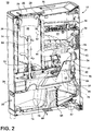
- FIG. 2 illustrates a cross-sectional view of the composter device 10 of FIG. 1 .
- the composter bin 24 can be fixedly or removable mounted to the housing 12.
- the composter bin 24 can define a chamber 36 configured to receive organic material from outside of the composting device 10, either directly or indirectly.
- the composter bin 24 can include an open top 28 of the bin 24 for receiving refuse through the top wall 20 of composting device 10.
- the top wall 20 can also include a funnel 29 located to align with the open top 28 of the composter bin 24 such that refuse placed in through the top wall 20 into the funnel 29 is guided into the open top 28 of the composter bin 24.
- the housing 12 can also include a porous wall 43, shown as a portion of the back wall 16, wherein the porous wall 43 is configured to allow ambient air to flow into or out of the interior 42 of the housing 12. While the portion of the back wall 16 has been illustrated having the porous wall, embodiments of the disclosure can include a porous portion of one or more of any of the previously described walls 14, 17, 20.
- a conduit 30 can extend from the composter bin 24, such as from a lower portion of the composter bin 24, toward the access drawer 26.
- Embodiments of the disclosure can optionally include a transfer mechanism disposed inside the conduit 30 capable of assisting the transfer of material from the composter bin 24 to the access drawer 26.
- Examples of a transfer mechanism can include, but are not limited to, a rotatable auger, a conveyor, a gravitational chute, and the like.
- a reducing mechanism 60 can be provided adjacent or within the composter bin 24.
- the reducing mechanism 60 can be in the form of a mixer, an auger, a grinding wheel, a grinding blade, any chopping mechanism, or any like device or combination thereof that grinds, shears chops, mixes, breaks, or otherwise reduces the particle sizes of refuse by the operation of the reducing mechanism 60 or uniformly mixing refuse with water, air or enzymes that can be introduced in the composter bin 24 for transforming the refuse into compost.
- a motor 70 can be provided inside the cabinet 12 and can be operably coupled to the reducing mechanism 60 to operate, rotate, toggle, or actuate the reducing mechanism 60. As shown, the motor 70 can be operatively coupled with the reducing mechanism 60 by way of a belt or pulley system 72.
- the motor 70 can be a brushless permanent magnet (BPM) motor. Alternately, other motors such as an induction motor or a permanent split capacitor (PSC) motor can also be used.
- the motor 70 can be configured to operate the reducing mechanism 60 at different speeds during the cycle of operation to facilitate the reducing or mixing of refuse in the interior of the composter bin 24 or the access drawer 26.
- the composter device 10 further includes a heat exchanger 34, an evaporation chamber or condensate reservoir 38, a filter 40, and an air supply system 32, all of which are located within an interior 42 of the housing 12.
- the heat exchanger 34 can include a fluid pathway 44 defined between a set of heat conducting elements 46, such as plates, configured such that the heat conducting elements 46 absorb, conduct, pull, or otherwise remove at least a portion of heat from air traversing the fluid pathway 44. At least a portion of the heat removed from the air traversing the fluid pathway 44 can be dissipated, conducted, or radiated into the air occupying the interior 42 of the housing 12.
- Embodiments of the disclosure can include a heat exchanger 34 having a fluid pathway 44 sealed, closed, or isolated from the interior 42 of the housing 12, such that heat can be removed or transferred out of the fluid pathway 44 without intermixing fluid traversing the pathway 44 with the interior 42.
- the condensate reservoir 38 can include a body 48 defining an interior 50 for holding liquid, such as water, and can be fluidly coupled downstream from the fluid pathway 44 of the heat exchanger 34.
- the condensate reservoir 38 can also include a second fluid coupling, separate from the fluid coupling with the fluid pathway 44 such as a controllable valve 62, configured to provide access to the interior 50 of the reservoir 38.
- the controllable valve 62 can be communicatively coupled with the controller 18, and can be configured to at least partially open, partially close, or actuate in response to instructions provided by the controller 18. In this sense, the controller 18 can operate the controllable valve 62 to provide selective access to the interior 50 of the reservoir 38. While a controllable valve 62 is described, embodiments of the disclosure can include a fixed opening or fixed port providing uncontrollable access to the interior 50 of the reservoir 38.
- the air supply system 32 provides air flow for the composting device 10.
- the air supply system 32 can include a fan 54 or vacuum pump for supplying, drawing, receiving, or forcing air, for example, through a first fluid pathway (illustrated as arrows 52).
- the first fluid pathway 52 can include, but is not limited to, a pathway defined to transmit composting air from the chamber 36 of the composter bin 24, for example through an opening 56 in the bin 24 wall, through the fluid pathway 44 of the heat exchanger 34, and into the interior 50 of the condensate reservoir 38.
- the first fluid pathway 52 can include tubing, closed channels, ducting, or the like to define sealed or contained pathway 52, since the composting air delivered may include undesirable odors or smells emitted as byproducts of the composting cycle of operation.
- the air supply system 32 can also include a fan 54 or vacuum pump for supplying drawing, receiving, or forcing air, for example through a second fluid pathway (illustrated as arrows 58).
- the second fluid pathway 58 can include, but is not limited to, a pathway defined to transmit ambient air from the interior 52 of the composting device 10 into the interior 50 condensate reservoir 38, for example, via the controllable valve 62.
- the ambient air can be drawn from ambient air external to the housing 12, such as through the porous wall 43, into the interior 42 of the composting device 10.
- the ambient air located within the interior 42 of the composting device 10 can also include a portion of air heated by way of the heat exchanger 34 dissipating, conducting, or radiating heat to the interior 42 of the housing 12, as explained above.
- the fan 54 configured to draw, receive, or force air along the first fluid pathway 52 can be the same fan 54 configured to draw, receive, or force air along the second fluid pathway 58.
- the controllable valve 62 can further be utilized to control the drawing of air along the first fluid pathway 52.
- the opening or closing of the controllable valve 62 can have the technical effect of redistributing or rebalancing the draw of the airflow from the respective first fluid pathway 52 and the second fluid pathway 58. For instance, restricting the second fluid pathway 58 by way of closing the controllable valve 62 produces additional airflow drawn from the first fluid pathway 52, whereas opening the controllable valve 62 reduces airflow drawn from the first fluid pathway 52.
- Alternative embodiments can include configurations wherein each fluid pathway 52, 58 as a different source, such as a set of fans 54, for supplying airflow in each respective pathway 52, 58.
- the fan 54 or vacuum pump can be configured to create negative pressure to draw air along at least one of the first fluid pathway 52 or second fluid pathway 58.
- the composting device 10 can additionally include a third fluid pathway (illustrated as arrows 64) configured to remove or vent air in the interior 50 of the condensate reservoir 38 to the outside of, or external to the housing 12.
- the third fluid pathway 64 can include a pathway sealed, closed, or isolated from the interior 42 of the housing 12, and configured to direct airflow through, for example, a filter 66 prior to venting the airflow through an air outlet 68, which is illustrated on a bottom wall 74 of the housing 12.
- the filter 66 can include a diffuser 67, or can be configured to filter or remove undesirable elements from the airflow downstream of the condensate reservoir 38.
- Undesirable elements can include, but are not limited to, odors or microbes originating from the composting cycle of operation.
- filter 66 materials can include, but are not limited to, charcoal, previously composted material, a biofilter material, or activated carbon.
- Additional filters 66 can include utilizing ultraviolet lighting or ozone, for example, via an ozone generator, to provide at least a portion of the filtering of undesirable elements from the airflow downstream of the condensate reservoir 38.
- the air supply system 32 or fan 54 can be located fluidly downstream of the condensate reservoir 38, such that the fan 54 can be configured to use suction force or low pressure to move airflow through the first or second fluid pathways 52, 58.
- the fan 54 can further be configured to push or force air through the third fluid pathway 64, which can be downstream from the condensate reservoir 38 or the fan 54.
- Alternative configurations can be included.
- the composting device 10 can additionally include a number of sensor 76 positioned throughout the device 10 communicatively coupled with the controller 18 to sense or measure characteristics, values, or indicators utilized to control or operate the device 10 or the composting cycle of operation.
- the sensors 76 can include, but are not limited to, humidity sensors, temperature sensors, moisture sensors, level sensors, odor sensors, pH sensors, water level sensors, weight sensors, airflow sensors, and the like. Two non-limiting examples of sensor 76 placement are illustrated to include in the interior 50 of the condensate reservoir 38 or downstream of the condensate reservoir 38, such as at the diffuser 67 or proximate to the filter 66. Additional examples of sensor 76 placement can be included.
- the controller 18 can be provided with a memory 80 and a central processing unit (CPU) 82.
- the memory 80 can be used for storing the control software that is executed by the CPU 82 in completing a cycle of operation using the composting device 10 and any additional software.
- the memory 80 can also be used to store information, such as a database or table, and to store data received from one or more components of the composting device 10 that can be communicably coupled with the controller 18.
- the controller 18 can be operably coupled with one or more components of the compositing device 10 for communicating with and controlling the operation of the component to complete a cycle of operation.
- the controller 18 can be operably coupled with the motor 70 to control the operation of the motor 70.
- the controller 18 can be operably coupled to the fan 54 for selectively operating the of the first, second, or third fluid pathways 52, 58, 64.
- the controller 18 can also be coupled with the one or more sensors 76 provided in one or more of the systems of the composting device 10 to receive input from the sensors.
- FIG. 4 illustrates a schematic view of the operation of the composting device 10.
- the composter bin 24 is fluidly coupled with the condensate reservoir 38 by way of the enclosed or sealed first fluid pathway 52 passing through the heat exchanger 34.
- ambient air 90 or outside air is fluidly coupled with the condensate reservoir 38 by way of the second fluid pathway 58, passing and absorbing at least a portion of heat from the heat exchanger 34 to define warm air 92.
- a first portion 94 of the warm air 92 can be selectively directed through the controllable valve 62 to the condensate reservoir 38.
- a second portion 96 of the warm air 92 can be vented from the composting device 10, and a third portion 98 of the warm air 92 can be optionally or selectively directed back to the composter bin 24 for further composting activity.
- refuse such as organic food waste or leaves
- the refuse can be provided by the user to the interior of the composter bin 24 through the opening or cover 22 of the top wall 20.
- the refuse can be supplied to the interior of the composter bin 24 over a period of time until the volume or weight of the refuse satisfies a predetermined threshold, as determined by a level sensor or a weight sensor.
- the composting cycle can begin when the level of refuse reaches a predetermined level or it can begin as soon as refuse is placed in the composter bin 24. Alternatively, the composting cycle can initiate as long as the level sensor or weight sensor determines that the refuse is received in the composter bin 24.
- the refuse can be uniformly mixed and decimated by rotating the reducing mechanism 60 positioned at the lower portion of the composter bin 24 at a predetermined speed according to the cycle of operation. Reducing can occur periodically or continuously.
- the refuse can also be provided with heat, water or aeration according to the cycle of operation to promote the decomposition of the refuse.
- an optional heating element can be controllably operated to maintain the temperature in the composter bin 24 within a predetermined temperature range.
- the predetermined temperature range can vary with the progress of composting process, and the temperature can be determined by a temperature sensor.
- the relative humidity level in the composter bin 24 can also be controlled by controllably operating the optional heating element to enhance the overall rate of composting process.
- Enzymes can be provided to the composter bin 24, the access drawer 26, or both by an enzyme dispenser for continuing and enhancing the composting process.
- the refuse can be further decomposed by controlling the amount of water and aeration in the refuse in the access drawer 26.
- Composting air that is, air generated by the composting cycle of operation, can enter the first fluid pathway 52 from the composter bin 24, or can be drawn by the fan 54 at, for example, a rate between 0.25 cubic feet per minute (CFM) and 1 CFM, and can have a temperature of 70 degrees Celsius with a high humidity.
- the composting air leaving the composter bin 24 can further include undesirable elements, as described above. While “humidity" is described, embodiments of the disclosure can include sensing, measuring, or estimations of the amount of water vapor in a portion or air.
- embodiments of the disclosure can be described in terms of “absolute humidity,” which is the water content of air at a given temperature, “relative humidity,” which is the current absolute humidity relative to the maximum absolute humidity for that temperature, or “specific humidity,” which is ratio of the water vapor content of the mixture to the total air content on a mass basis.
- absolute humidity which is the water content of air at a given temperature
- relative humidity which is the current absolute humidity relative to the maximum absolute humidity for that temperature
- specific humidity which is ratio of the water vapor content of the mixture to the total air content on a mass basis.
- the composting air entering the first fluid pathway from the composter bin 24 can include 100 percent relative humidity.
- the temperature of the composting air can be cooled or reduced by 20 to 30 degree Celsius.
- the reduction in temperature of the composting air causes condensation, or excess moisture or water vapor, to fall out of or condense from the air, gathering as liquid.
- the liquid condensation can also flow through the first fluid pathway 52 exiting the heat exchanger 34, and gather in the condensate reservoir 38, illustrated as water 100. While "water” is described, embodiments of the disclosure can include examples wherein the water 100 is not pure water, and can include amounts of compost, odor and bacteria.
- the cooled composting air traverses the portion of the first fluid pathway 52 downstream from the heat exchanger 34, and ultimately enters the condensate reservoir 38.
- a first airflow passes from the composting bin 24, through the heat exchanger 34 where heat is removed from the first airflow and condensation forms, and the first airflow and condensation are each provided to the condensate reservoir 38.
- the first fluid pathway 52 can include a liquid pathway configured to deliver the condensate or water 100 to the reservoir 38.
- Ambient air 90 is entering the second fluid pathway 58 can be drawn by the fan 54 or forced across the heat exchanger 34 at 20 to 30 CFM and can have a nominal temperature of 20 degrees Celsius with a relative humidity of 50 percent.
- the ambient air 90 is used to cool the heat exchanger 34, which in turn, raises the temperature of the ambient air 90 to the warm air 92 to, for example, 42 degrees Celsius, and lower the relative humidity of the warm air to 14 percent.
- a first portion 94 of the warm air 92 can be directed into the condensation reservoir 38 by way of the selectively operable controllable valve 62.
- a second airflow includes ambient air 90 passing the heat exchanger 34, warming the ambient air 90, which can further be directed into the condensate reservoir 38.
- the second fluid pathway 58 is fluidly isolated from the first fluid pathway 52, and the second fluid pathway 58 is in heat transfer juxtaposition with the first fluid pathway 52.
- the controllable valve 62 operates to provide, match, maintain, or regulate a target characteristic of air passing through the condensate reservoir 38.
- Operating the valve 62 to match, maintain, or regulate the target characteristic of air passing through the reservoir 38 enables the condensation or water 100 to evaporate over an evaporation cycle of operation, which can be different from the composting cycle of operation.
- a composting cycle of operation for 3.5 kilograms of refuse can last for 24 hours.
- evaporation of 1.5 liters of water 100 i.e. an example amount of water 100 condensed during a 3.5 kilograms of refuse composting cycle
- evaporation of 1.5 liters of water 100 i.e. an example amount of water 100 condensed during a 3.5 kilograms of refuse composting cycle
- in the condensate reservoir 38 can take approximately 5.5 days according to embodiments of the disclosure.
- the fan 54 can be configured to operate, for example, by the controller 18, for the evaporation period, even if after the composting cycle of operation has completed.
- the fan 54 can be configured to operate selectively or intermittently, as needed, or as controlled by the controller 18.
- the target characteristic of air can include at least one of a temperature characteristic or a humidity characteristic.
- the target characteristic of air passing through the condensate reservoir 38 can include a mixture of air received from the first fluid pathway 52 and the second fluid pathway 58 at, for example, a target temperature characteristic between 41 degrees Celsius and 43 degrees Celsius, and having a target humidity characteristic of a relative humidity between 27 percent and 37 percent.
- the actual characteristics of the air passing through the condensate reservoir 38 can be sensed or measured directly or indirectly by, for example, the sensor 76 positioned in the interior 50 of the reservoir 38.
- the controller 18 can be configured to receive the sensed or measured actual characteristics of the air, and adjust, modify, actuate, operate, open, or close the controllable valve 62 to modify the air mixture passing thorough the reservoir 38, if needed, based at least on the characteristics received from the sensor 76.
- the first airflow received via the first fluid pathway 52 is modified by the second airflow controllably received via the second fluid pathway 58 and controllable valve 62 to match, maintain, or attain the target characteristic of air passing through the reservoir 38.
- the mixture of air from the first and second fluid pathways 52, 58 is further drawn or forced out of the condensate reservoir 38 by the fan 54, and into the third fluid pathway 64, wherein the third airflow traversing the third fluid pathway 64 can pass through the filter 66, or additional optional components including, but not limited to, an ozone generator or a desiccant, before being vented outside of the housing 12.
- Example characteristics of the third airflow traversing the third fluid pathway 64 can include a relative humidity less than 60 percent.
- Alternative embodiments of the disclosure can include configurations wherein, for example, the actual characteristics of the air passing through the condensate reservoir 38 can be sensed or measured directly or indirectly by the sensor 76 positioned downstream of the reservoir 38, such as in the third fluid pathway 64.
- the controller 18 can be configured to operate the controllable valve 62 to match, maintain, or attain a target characteristic of air passing through the third fluid pathway, which can be different than the target characteristic of air passing through the reservoir 38.
- the airflow traversing the third fluid pathway 64 can having a higher target humidity characteristic than the airflow passing through the reservoir 38, since the airflow traversing the third fluid pathway 64 will include at least some additional evaporate from the reservoir 38.
- temperature values, humidity values, and airflow values have been described at various locations of the composter device, additional or alternative values can be included, and embodiments of the disclosure are not limited to only those examples provided. Likewise, embodiment of the disclosure can include additional or alternative target characteristics, such as target temperature or target humidity characteristics.
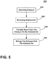
- FIG. 5 illustrates a method 200 of operating a composter 10 having a composter bin 24 or container and a condensate reservoir 38.
- the method 200 includes directing exhaust from the composter bin 24 to the condensate reservoir 38 by way of the first fluid pathway 52.
- the method 200 includes directing ambient air 90 to the condensate reservoir 38 by way of a second fluid pathway 58.
- the method 200 includes transferring heat from the first fluid pathway 52 to the second fluid pathway 58 prior to the mixing in the condensate reservoir 38.
- the method 200 includes mixing the exhaust from the first fluid pathway 52 and the ambient air 90 from the second fluid pathway 58 in the condensate reservoir 38.
- the transferring step 230 can include lowering the relative humidity of the exhaust, via the heat exchanger 34, or condensing liquid from the exhaust while the first fluid pathway 52 directs the condensed liquid to the condensate reservoir 38.
- the mixing step 240 can include selectively operating the controllable valve 62 along the second fluid pathway 58 to control the ratio of exhaust and ambient air 90 in the condensate reservoir 38.
- the selectively operating the controllable valve 62 can be configured to create a mixture of air in the condensate reservoir 38 configured to evaporate liquid or water 100 in the reservoir 38 over multiple days, as explained above.
- the method 200 can include venting the mixture of the air in the condensate reservoir 38 outside of the composting device 10 or into the ambient air 90 by way of the third fluid pathway 64.
- the directing the ambient air step 220 can include directing ambient air 90 through the porous wall 43 of the composter device 10 to the interior 42, and directing air in the interior 42 of the device 10 to the condensate reservoir 38.
- the embodiments disclosed herein provide a composter and method for operating a composter.
- One advantage that can be realized in the above embodiments is that the above described embodiments are configured to provide a composting device capable of pulling air through the compost bin to dry the composting materials during the composting cycle of operation. By fluidly sealing or isolating the first fluid pathway, the composting air having odor or other undesirable characteristics can be cooled, and transferred along the fluid pathways to the filter, which removes the undesirable characteristics, without exposing a user or an environment to those undesirable characteristics.
- the compost device can effectively manage moisture removed during the composting cycle of operation by using the heat exchanger to condense a portion of the moisture into the condensate reservoir, where it can be slowly evaporated over a period of time.
- This purposeful condensing prevents unintended or unanticipated condensing downstream of the fluid pathways, which can damage components such as the fan, filter, or otherwise expose a user's environment to the condensation (e.g. a kitchen floor that gathers condensation puddles when operating a composting cycle of operation).
Landscapes
- Chemical & Material Sciences (AREA)
- Chemical Kinetics & Catalysis (AREA)
- Life Sciences & Earth Sciences (AREA)
- Engineering & Computer Science (AREA)
- Biochemistry (AREA)
- Biotechnology (AREA)
- Health & Medical Sciences (AREA)
- General Chemical & Material Sciences (AREA)
- Microbiology (AREA)
- Molecular Biology (AREA)
- Organic Chemistry (AREA)
- Fertilizers (AREA)
- Processing Of Solid Wastes (AREA)
Abstract
Description
- Composting devices are known to implement a composting cycle for biologically and chemically decomposing organic material, such as food waste, into compost for use as a fertilizer and soil amendment. The composting cycle can be implemented in a composting bin by providing water, heat and aeration to the refuse, and can require a period of time for completion. Composting devices usually require a large floor space or a large volume for installation. Further, some composting devices can be a batch type device, therefore cannot be effective in producing compost in a continuous way.
- In one aspect, a composter includes a compost chamber, a condensate reservoir, a first fluid pathway fluidly coupling the composting chamber and the condensate reservoir, a second fluid pathway coupling ambient air and the condensate reservoir and in heat transfer juxtaposition with the first fluid pathway, and a fan moving air from the composting chamber to the condensate reservoir along the first fluid pathway to define a first airflow and moving ambient air to the condensate reservoir along the second fluid pathway to define a second airflow. The second fluid pathway is fluidly isolated from the first fluid pathway, and the first and second airflows mix in the condensate reservoir.
- In another aspect, a method of operating a composter having a composting container and a condensate reservoir includes directing exhaust from the composting container to the condensate reservoir by way of a first fluid pathway, directing ambient air to the condensate reservoir by way of a second fluid pathway, mixing the exhaust from the first fluid pathway and the ambient air from the second fluid pathway in the condensate reservoir, and transferring heat from the first fluid pathway to the second fluid pathway prior to the mixing in the condensate reservoir.
- In the drawings:
-
FIG. 1 is a perspective view of a composting device. -
FIG. 2 is an example schematic cross-sectional illustration of the composting device ofFIG. 1 . -
FIG. 3 is a block diagram of a control system of the composting device. -
FIG. 4 is a schematic illustration of the operation of the composting device. -
FIG. 5 is a flowchart illustrating a method of operating the composting device. -
FIG. 1 illustrates a perspective view of acomposting device 10 or composter for transforming organic material into compost by way of a composting cycle of operation. While a "composting device" or "composter" is described, embodiments of the invention can be equally applicable for similar devices, such as food recyclers or biological waste digesters. Thecomposting device 10 can include ahousing 12 having afront wall 14 spaced from aback wall 16, a pair ofside walls 17, and acontroller 18 located within thehousing 12. - A
top wall 20 can enclose thehousing 12 at the top of thefront wall 14,back wall 16, and the pair ofside walls 17. Thehousing 12 can be any structure for enclosing, supporting and protecting the electrical and mechanical components of thecomposting device 10 including, but not limited to a cabinet and a frame. - The
top wall 20 can include acover 22 slidably mounted to a portion of thetop wall 20 for sliding movement between open or closed positions to enable access to interior components of thecomposting device 10. Thecover 22 can be any barrier that provides selective access for inputting organic material into thecomposting device 10, including, but not limited to a hingedly, slidably or removably mounted door, drawer, panel or lid. While shown inFIG. 1 as coupled to thetop wall 20, thecover 22 can be mounted to any exterior wall enclosing thehousing 12 including, but not limited to thefront wall 14. Thetop wall 20, as well as the remainder of thehousing 12, can be formed of any material suitable for construction of the housing structure including, but not limited to metal such as steel or steel alloy, plastic, composite materials such as a hardened polymer composite material and combinations thereof. Some models ofcomposting devices 10 can include decorative panels that can be mounted on thehousing 12 or one or more walls. - When in the open position, the
cover 22 provides access to the interior of thehousing 12. In the open position, the cover can further expose any element of thecomposting device 10 interior of thehousing 12 including but not limited to one or more water fill inlets for supplying water to thecomposting device 10 and one or more enzyme dispenser inlets. Acomposter bin 24 is provided within thehousing 12. Thecomposter bin 24 can be disposed beneath thecover 22 such that the cover provides selective access to thecomposter bin 24 as the cover is opened/closed. - An
access drawer 26 is provided and slides in or out through an opening in thefront wall 14. Theaccess drawer 26 is a drawer slidably mounted to thehousing 12 on a horizontal axis for movement between open and closed positions. It will be understood, however, that access to the interior of thecomposting device 10 via thefront wall 14 can be provided in other ways, including but not limited to, a door pivotally connected to thefront wall 14. The access drawer can be detachably mounted to an internal side of thehousing 12 and is accessible from outside thehousing 12. Theaccess drawer 26 can be removable from the interior of thehousing 12 so that the contents thereof can be discharged at will by a user, as for example, by dumping the contents of thedrawer 26 onto a garden. -
FIG. 2 illustrates a cross-sectional view of thecomposter device 10 ofFIG. 1 . Thecomposter bin 24 can be fixedly or removable mounted to thehousing 12. Thecomposter bin 24 can define achamber 36 configured to receive organic material from outside of thecomposting device 10, either directly or indirectly. Thecomposter bin 24 can include anopen top 28 of thebin 24 for receiving refuse through thetop wall 20 ofcomposting device 10. As shown, thetop wall 20 can also include afunnel 29 located to align with theopen top 28 of thecomposter bin 24 such that refuse placed in through thetop wall 20 into thefunnel 29 is guided into theopen top 28 of thecomposter bin 24. - The
housing 12 can also include aporous wall 43, shown as a portion of theback wall 16, wherein theporous wall 43 is configured to allow ambient air to flow into or out of theinterior 42 of thehousing 12. While the portion of theback wall 16 has been illustrated having the porous wall, embodiments of the disclosure can include a porous portion of one or more of any of the previously describedwalls - As shown, a
conduit 30 can extend from thecomposter bin 24, such as from a lower portion of thecomposter bin 24, toward theaccess drawer 26. Embodiments of the disclosure can optionally include a transfer mechanism disposed inside theconduit 30 capable of assisting the transfer of material from thecomposter bin 24 to theaccess drawer 26. Examples of a transfer mechanism can include, but are not limited to, a rotatable auger, a conveyor, a gravitational chute, and the like. - A reducing
mechanism 60 can be provided adjacent or within thecomposter bin 24. The reducingmechanism 60 can be in the form of a mixer, an auger, a grinding wheel, a grinding blade, any chopping mechanism, or any like device or combination thereof that grinds, shears chops, mixes, breaks, or otherwise reduces the particle sizes of refuse by the operation of the reducingmechanism 60 or uniformly mixing refuse with water, air or enzymes that can be introduced in thecomposter bin 24 for transforming the refuse into compost. - A
motor 70 can be provided inside thecabinet 12 and can be operably coupled to the reducingmechanism 60 to operate, rotate, toggle, or actuate the reducingmechanism 60. As shown, themotor 70 can be operatively coupled with the reducingmechanism 60 by way of a belt orpulley system 72. Themotor 70 can be a brushless permanent magnet (BPM) motor. Alternately, other motors such as an induction motor or a permanent split capacitor (PSC) motor can also be used. Themotor 70 can be configured to operate the reducingmechanism 60 at different speeds during the cycle of operation to facilitate the reducing or mixing of refuse in the interior of thecomposter bin 24 or theaccess drawer 26. - The
composter device 10 further includes aheat exchanger 34, an evaporation chamber orcondensate reservoir 38, a filter 40, and anair supply system 32, all of which are located within aninterior 42 of thehousing 12. - The
heat exchanger 34 can include afluid pathway 44 defined between a set ofheat conducting elements 46, such as plates, configured such that theheat conducting elements 46 absorb, conduct, pull, or otherwise remove at least a portion of heat from air traversing thefluid pathway 44. At least a portion of the heat removed from the air traversing thefluid pathway 44 can be dissipated, conducted, or radiated into the air occupying theinterior 42 of thehousing 12. Embodiments of the disclosure can include aheat exchanger 34 having afluid pathway 44 sealed, closed, or isolated from theinterior 42 of thehousing 12, such that heat can be removed or transferred out of thefluid pathway 44 without intermixing fluid traversing thepathway 44 with theinterior 42. - The
condensate reservoir 38 can include abody 48 defining an interior 50 for holding liquid, such as water, and can be fluidly coupled downstream from thefluid pathway 44 of theheat exchanger 34. Thecondensate reservoir 38 can also include a second fluid coupling, separate from the fluid coupling with thefluid pathway 44 such as acontrollable valve 62, configured to provide access to theinterior 50 of thereservoir 38. Thecontrollable valve 62 can be communicatively coupled with thecontroller 18, and can be configured to at least partially open, partially close, or actuate in response to instructions provided by thecontroller 18. In this sense, thecontroller 18 can operate thecontrollable valve 62 to provide selective access to theinterior 50 of thereservoir 38. While acontrollable valve 62 is described, embodiments of the disclosure can include a fixed opening or fixed port providing uncontrollable access to theinterior 50 of thereservoir 38. - The
air supply system 32 provides air flow for thecomposting device 10. Theair supply system 32 can include afan 54 or vacuum pump for supplying, drawing, receiving, or forcing air, for example, through a first fluid pathway (illustrated as arrows 52). Thefirst fluid pathway 52 can include, but is not limited to, a pathway defined to transmit composting air from thechamber 36 of thecomposter bin 24, for example through anopening 56 in thebin 24 wall, through thefluid pathway 44 of theheat exchanger 34, and into theinterior 50 of thecondensate reservoir 38. Thefirst fluid pathway 52 can include tubing, closed channels, ducting, or the like to define sealed or containedpathway 52, since the composting air delivered may include undesirable odors or smells emitted as byproducts of the composting cycle of operation. - The
air supply system 32 can also include afan 54 or vacuum pump for supplying drawing, receiving, or forcing air, for example through a second fluid pathway (illustrated as arrows 58). Thesecond fluid pathway 58 can include, but is not limited to, a pathway defined to transmit ambient air from theinterior 52 of thecomposting device 10 into the interior 50condensate reservoir 38, for example, via thecontrollable valve 62. In one embodiment, the ambient air can be drawn from ambient air external to thehousing 12, such as through theporous wall 43, into the interior 42 of thecomposting device 10. The ambient air located within theinterior 42 of thecomposting device 10 can also include a portion of air heated by way of theheat exchanger 34 dissipating, conducting, or radiating heat to the interior 42 of thehousing 12, as explained above. Thefan 54 configured to draw, receive, or force air along thefirst fluid pathway 52 can be thesame fan 54 configured to draw, receive, or force air along thesecond fluid pathway 58. In this sense, thecontrollable valve 62 can further be utilized to control the drawing of air along thefirst fluid pathway 52. For example, if thefan 54 draws a predetermined amount of airflow from theinterior 50 of thecondensate reservoir 38, the opening or closing of thecontrollable valve 62 can have the technical effect of redistributing or rebalancing the draw of the airflow from the respective firstfluid pathway 52 and thesecond fluid pathway 58. For instance, restricting thesecond fluid pathway 58 by way of closing thecontrollable valve 62 produces additional airflow drawn from thefirst fluid pathway 52, whereas opening thecontrollable valve 62 reduces airflow drawn from thefirst fluid pathway 52. Alternative embodiments can include configurations wherein eachfluid pathway fans 54, for supplying airflow in eachrespective pathway fan 54 or vacuum pump can be configured to create negative pressure to draw air along at least one of thefirst fluid pathway 52 or secondfluid pathway 58. - The
composting device 10 can additionally include a third fluid pathway (illustrated as arrows 64) configured to remove or vent air in theinterior 50 of thecondensate reservoir 38 to the outside of, or external to thehousing 12. For example, the thirdfluid pathway 64 can include a pathway sealed, closed, or isolated from theinterior 42 of thehousing 12, and configured to direct airflow through, for example, afilter 66 prior to venting the airflow through anair outlet 68, which is illustrated on abottom wall 74 of thehousing 12. Thefilter 66 can include adiffuser 67, or can be configured to filter or remove undesirable elements from the airflow downstream of thecondensate reservoir 38. Undesirable elements can include, but are not limited to, odors or microbes originating from the composting cycle of operation. Examples offilter 66 materials can include, but are not limited to, charcoal, previously composted material, a biofilter material, or activated carbon.Additional filters 66 can include utilizing ultraviolet lighting or ozone, for example, via an ozone generator, to provide at least a portion of the filtering of undesirable elements from the airflow downstream of thecondensate reservoir 38. - In the embodiment illustrated, the
air supply system 32 orfan 54 can be located fluidly downstream of thecondensate reservoir 38, such that thefan 54 can be configured to use suction force or low pressure to move airflow through the first or secondfluid pathways fan 54 can further be configured to push or force air through the thirdfluid pathway 64, which can be downstream from thecondensate reservoir 38 or thefan 54. Alternative configurations can be included. - The
composting device 10 can additionally include a number ofsensor 76 positioned throughout thedevice 10 communicatively coupled with thecontroller 18 to sense or measure characteristics, values, or indicators utilized to control or operate thedevice 10 or the composting cycle of operation. Thesensors 76 can include, but are not limited to, humidity sensors, temperature sensors, moisture sensors, level sensors, odor sensors, pH sensors, water level sensors, weight sensors, airflow sensors, and the like. Two non-limiting examples ofsensor 76 placement are illustrated to include in theinterior 50 of thecondensate reservoir 38 or downstream of thecondensate reservoir 38, such as at thediffuser 67 or proximate to thefilter 66. Additional examples ofsensor 76 placement can be included. - Referring now to
FIG. 3 , a schematic of thecontroller 18 for controlling the operation of thecomposting device 10 is illustrated. Thecontroller 18 can be provided with amemory 80 and a central processing unit (CPU) 82. Thememory 80 can be used for storing the control software that is executed by theCPU 82 in completing a cycle of operation using thecomposting device 10 and any additional software. Thememory 80 can also be used to store information, such as a database or table, and to store data received from one or more components of thecomposting device 10 that can be communicably coupled with thecontroller 18. - The
controller 18 can be operably coupled with one or more components of thecompositing device 10 for communicating with and controlling the operation of the component to complete a cycle of operation. For example, thecontroller 18 can be operably coupled with themotor 70 to control the operation of themotor 70. In another example, thecontroller 18 can be operably coupled to thefan 54 for selectively operating the of the first, second, or thirdfluid pathways controller 18 can also be coupled with the one ormore sensors 76 provided in one or more of the systems of thecomposting device 10 to receive input from the sensors. -
FIG. 4 illustrates a schematic view of the operation of thecomposting device 10. As shown, thecomposter bin 24 is fluidly coupled with thecondensate reservoir 38 by way of the enclosed or sealedfirst fluid pathway 52 passing through theheat exchanger 34. Additionally,ambient air 90 or outside air is fluidly coupled with thecondensate reservoir 38 by way of thesecond fluid pathway 58, passing and absorbing at least a portion of heat from theheat exchanger 34 to definewarm air 92. Afirst portion 94 of thewarm air 92 can be selectively directed through thecontrollable valve 62 to thecondensate reservoir 38. Also shown, asecond portion 96 of thewarm air 92 can be vented from thecomposting device 10, and athird portion 98 of thewarm air 92 can be optionally or selectively directed back to thecomposter bin 24 for further composting activity. - During a composting cycle of operation, refuse, such as organic food waste or leaves, can be provided by the user to the interior of the
composter bin 24 through the opening or cover 22 of thetop wall 20. The refuse can be supplied to the interior of thecomposter bin 24 over a period of time until the volume or weight of the refuse satisfies a predetermined threshold, as determined by a level sensor or a weight sensor. The composting cycle can begin when the level of refuse reaches a predetermined level or it can begin as soon as refuse is placed in thecomposter bin 24. Alternatively, the composting cycle can initiate as long as the level sensor or weight sensor determines that the refuse is received in thecomposter bin 24. - The refuse can be uniformly mixed and decimated by rotating the reducing
mechanism 60 positioned at the lower portion of thecomposter bin 24 at a predetermined speed according to the cycle of operation. Reducing can occur periodically or continuously. The refuse can also be provided with heat, water or aeration according to the cycle of operation to promote the decomposition of the refuse. - During the composting process, an optional heating element can be controllably operated to maintain the temperature in the
composter bin 24 within a predetermined temperature range. The predetermined temperature range can vary with the progress of composting process, and the temperature can be determined by a temperature sensor. Further, the relative humidity level in thecomposter bin 24 can also be controlled by controllably operating the optional heating element to enhance the overall rate of composting process. - While the composting process proceeds in the
composter bin 24, partially composted refuse is transferred from thecomposter bin 24 to theaccess drawer 26. Enzymes can be provided to thecomposter bin 24, theaccess drawer 26, or both by an enzyme dispenser for continuing and enhancing the composting process. The refuse can be further decomposed by controlling the amount of water and aeration in the refuse in theaccess drawer 26. - Composting air, that is, air generated by the composting cycle of operation, can enter the
first fluid pathway 52 from thecomposter bin 24, or can be drawn by thefan 54 at, for example, a rate between 0.25 cubic feet per minute (CFM) and 1 CFM, and can have a temperature of 70 degrees Celsius with a high humidity. The composting air leaving thecomposter bin 24 can further include undesirable elements, as described above. While "humidity" is described, embodiments of the disclosure can include sensing, measuring, or estimations of the amount of water vapor in a portion or air. For example, embodiments of the disclosure can be described in terms of "absolute humidity," which is the water content of air at a given temperature, "relative humidity," which is the current absolute humidity relative to the maximum absolute humidity for that temperature, or "specific humidity," which is ratio of the water vapor content of the mixture to the total air content on a mass basis. The examples presented herein will be described in relative humidity examples, but alternative humidity measurement or descriptions can be included. For example, the composting air entering the first fluid pathway from thecomposter bin 24 can include 100 percent relative humidity. - As the composting air in the
first fluid pathway 52 moves through theheat exchanger 34, the temperature of the composting air can be cooled or reduced by 20 to 30 degree Celsius. The reduction in temperature of the composting air, in turn, causes condensation, or excess moisture or water vapor, to fall out of or condense from the air, gathering as liquid. The liquid condensation can also flow through thefirst fluid pathway 52 exiting theheat exchanger 34, and gather in thecondensate reservoir 38, illustrated aswater 100. While "water" is described, embodiments of the disclosure can include examples wherein thewater 100 is not pure water, and can include amounts of compost, odor and bacteria. The cooled composting air traverses the portion of thefirst fluid pathway 52 downstream from theheat exchanger 34, and ultimately enters thecondensate reservoir 38. In this sense, a first airflow passes from thecomposting bin 24, through theheat exchanger 34 where heat is removed from the first airflow and condensation forms, and the first airflow and condensation are each provided to thecondensate reservoir 38. Additionally, at least a portion of thefirst fluid pathway 52 can include a liquid pathway configured to deliver the condensate orwater 100 to thereservoir 38. -
Ambient air 90 is entering thesecond fluid pathway 58 can be drawn by thefan 54 or forced across theheat exchanger 34 at 20 to 30 CFM and can have a nominal temperature of 20 degrees Celsius with a relative humidity of 50 percent. Theambient air 90 is used to cool theheat exchanger 34, which in turn, raises the temperature of theambient air 90 to thewarm air 92 to, for example, 42 degrees Celsius, and lower the relative humidity of the warm air to 14 percent. Afirst portion 94 of thewarm air 92 can be directed into thecondensation reservoir 38 by way of the selectively operablecontrollable valve 62. In this sense, a second airflow includesambient air 90 passing theheat exchanger 34, warming theambient air 90, which can further be directed into thecondensate reservoir 38. Additionally, thesecond fluid pathway 58 is fluidly isolated from thefirst fluid pathway 52, and thesecond fluid pathway 58 is in heat transfer juxtaposition with thefirst fluid pathway 52. - The
controllable valve 62 operates to provide, match, maintain, or regulate a target characteristic of air passing through thecondensate reservoir 38. Operating thevalve 62 to match, maintain, or regulate the target characteristic of air passing through thereservoir 38 enables the condensation orwater 100 to evaporate over an evaporation cycle of operation, which can be different from the composting cycle of operation. For example, a composting cycle of operation for 3.5 kilograms of refuse can last for 24 hours. Conversely, evaporation of 1.5 liters of water 100 (i.e. an example amount ofwater 100 condensed during a 3.5 kilograms of refuse composting cycle) in thecondensate reservoir 38 can take approximately 5.5 days according to embodiments of the disclosure. In this example, thefan 54 can be configured to operate, for example, by thecontroller 18, for the evaporation period, even if after the composting cycle of operation has completed. Alternatively, thefan 54 can be configured to operate selectively or intermittently, as needed, or as controlled by thecontroller 18. The target characteristic of air can include at least one of a temperature characteristic or a humidity characteristic. - The target characteristic of air passing through the
condensate reservoir 38 can include a mixture of air received from thefirst fluid pathway 52 and thesecond fluid pathway 58 at, for example, a target temperature characteristic between 41 degrees Celsius and 43 degrees Celsius, and having a target humidity characteristic of a relative humidity between 27 percent and 37 percent. The actual characteristics of the air passing through thecondensate reservoir 38 can be sensed or measured directly or indirectly by, for example, thesensor 76 positioned in theinterior 50 of thereservoir 38. Thecontroller 18 can be configured to receive the sensed or measured actual characteristics of the air, and adjust, modify, actuate, operate, open, or close thecontrollable valve 62 to modify the air mixture passing thorough thereservoir 38, if needed, based at least on the characteristics received from thesensor 76. In this sense, the first airflow received via thefirst fluid pathway 52 is modified by the second airflow controllably received via thesecond fluid pathway 58 andcontrollable valve 62 to match, maintain, or attain the target characteristic of air passing through thereservoir 38. - The mixture of air from the first and second
fluid pathways condensate reservoir 38 by thefan 54, and into the thirdfluid pathway 64, wherein the third airflow traversing the thirdfluid pathway 64 can pass through thefilter 66, or additional optional components including, but not limited to, an ozone generator or a desiccant, before being vented outside of thehousing 12. Example characteristics of the third airflow traversing the thirdfluid pathway 64 can include a relative humidity less than 60 percent. - Alternative embodiments of the disclosure can include configurations wherein, for example, the actual characteristics of the air passing through the
condensate reservoir 38 can be sensed or measured directly or indirectly by thesensor 76 positioned downstream of thereservoir 38, such as in the thirdfluid pathway 64. In this embodiment, thecontroller 18 can be configured to operate thecontrollable valve 62 to match, maintain, or attain a target characteristic of air passing through the third fluid pathway, which can be different than the target characteristic of air passing through thereservoir 38. For example, the airflow traversing the thirdfluid pathway 64 can having a higher target humidity characteristic than the airflow passing through thereservoir 38, since the airflow traversing the thirdfluid pathway 64 will include at least some additional evaporate from thereservoir 38. - While examples of temperature values, humidity values, and airflow values have been described at various locations of the composter device, additional or alternative values can be included, and embodiments of the disclosure are not limited to only those examples provided. Likewise, embodiment of the disclosure can include additional or alternative target characteristics, such as target temperature or target humidity characteristics.
-
FIG. 5 illustrates amethod 200 of operating acomposter 10 having acomposter bin 24 or container and acondensate reservoir 38. In afirst step 210, themethod 200 includes directing exhaust from thecomposter bin 24 to thecondensate reservoir 38 by way of thefirst fluid pathway 52. In asecond step 220, themethod 200 includes directingambient air 90 to thecondensate reservoir 38 by way of asecond fluid pathway 58. In athird step 230, themethod 200 includes transferring heat from thefirst fluid pathway 52 to thesecond fluid pathway 58 prior to the mixing in thecondensate reservoir 38. In afourth step 240, themethod 200 includes mixing the exhaust from thefirst fluid pathway 52 and theambient air 90 from thesecond fluid pathway 58 in thecondensate reservoir 38. - Alternative examples of the
method 200 can be included in embodiments of the disclosure. For example, the transferringstep 230 can include lowering the relative humidity of the exhaust, via theheat exchanger 34, or condensing liquid from the exhaust while thefirst fluid pathway 52 directs the condensed liquid to thecondensate reservoir 38. In another example of themethod 200, the mixingstep 240 can include selectively operating thecontrollable valve 62 along thesecond fluid pathway 58 to control the ratio of exhaust andambient air 90 in thecondensate reservoir 38. In this example embodiment, the selectively operating thecontrollable valve 62 can be configured to create a mixture of air in thecondensate reservoir 38 configured to evaporate liquid orwater 100 in thereservoir 38 over multiple days, as explained above. Additionally, themethod 200 can include venting the mixture of the air in thecondensate reservoir 38 outside of thecomposting device 10 or into theambient air 90 by way of the thirdfluid pathway 64. In yet another embodiment of themethod 200, the directing theambient air step 220 can include directingambient air 90 through theporous wall 43 of thecomposter device 10 to the interior 42, and directing air in theinterior 42 of thedevice 10 to thecondensate reservoir 38. - The sequence depicted is for illustrative purposes only and is not meant to limit the
method 200 in any way as it is understood that the portions of the method can proceed in a different logical order, additional or intervening portions can be included, or described portions of the method can be divided into multiple portions, or described portions of the method can be omitted without detracting from the described method. - The embodiments disclosed herein provide a composter and method for operating a composter. One advantage that can be realized in the above embodiments is that the above described embodiments are configured to provide a composting device capable of pulling air through the compost bin to dry the composting materials during the composting cycle of operation. By fluidly sealing or isolating the first fluid pathway, the composting air having odor or other undesirable characteristics can be cooled, and transferred along the fluid pathways to the filter, which removes the undesirable characteristics, without exposing a user or an environment to those undesirable characteristics.
- Another advantage of the above-described embodiments is that the compost device can effectively manage moisture removed during the composting cycle of operation by using the heat exchanger to condense a portion of the moisture into the condensate reservoir, where it can be slowly evaporated over a period of time. This purposeful condensing prevents unintended or unanticipated condensing downstream of the fluid pathways, which can damage components such as the fan, filter, or otherwise expose a user's environment to the condensation (e.g. a kitchen floor that gathers condensation puddles when operating a composting cycle of operation).
- To the extent not already described, the different features and structures of the various embodiments can be used in combination with each other as desired. That one feature cannot be illustrated in all of the embodiments is not meant to be construed that it cannot be, but is done for brevity of description. Thus, the various features of the different embodiments can be mixed and matched as desired to form new embodiments, whether or not the new embodiments are expressly described. Moreover, while "a set of" various elements have been described, it will be understood that "a set" can include any number of the respective elements, including only one element. Combinations or permutations of features described herein are covered by this disclosure.
- This written description uses examples to disclose embodiments of the invention, and also to enable any person skilled in the art to practice embodiments of the invention, including making and using any devices or systems and performing any incorporated methods. The patentable scope of the invention is defined by the claims, and can include other examples that occur to those skilled in the art. Such other examples are intended to be within the scope of the claims if they have structural elements that do not differ from the literal language of the claims, or if they include equivalent structural elements with insubstantial differences from the literal languages of the claims.
Claims (15)
- A composter (10) comprising:a compost chamber (36);a condensate reservoir (38);a first fluid pathway (52) fluidly coupling the composting chamber (36) and the condensate reservoir (38);a second fluid pathway (58) coupling ambient air and the condensate reservoir (38) and in heat transfer juxtaposition with the first fluid pathway (52); anda fan (54) moving air from the composting chamber (36) to the condensate reservoir (38) along the first fluid pathway (52) to define a first airflow and moving ambient air to the condensate reservoir (38) along the second fluid pathway (58) to define a second airflow;wherein the second fluid pathway (58) is fluidly isolated from the first fluid pathway (52), and the first and second airflows mix in the condensate reservoir (38).
- The composter (10) of claim 1 wherein the fan (54) is downstream from the condensate reservoir (38).
- The composter (10) of claim 2 wherein the fan (54) is a suction fan that generates a low pressure to draw air along the first fluid pathway (52) and along the second fluid pathway (58).
- The composter (10) of claim 1 wherein the second fluid pathway (58) includes a controllable valve (62) that selectively provides ambient air along the second fluid pathway (58).
- The composter (10) of claim 4 further including at least one of a temperature sensor or a humidity sensor located proximate to the compost chamber (36).
- The composter (10) of claim 5 further including a controller (18) communicatively coupled with the controllable valve (62) and configured to operate the controllable valve (62) based on the at least one of the temperature sensor or humidity sensor.
- The composter (10) of claim 1 further including a heat exchanger (34) positioned along the first fluid pathway (52) between the compost chamber (36) and the condensate reservoir (38) to reduce the temperature of the first airflow.
- The composter (10) of claim 7 wherein the heat exchanger (34) is exposed to the ambient air along the second fluid pathway (58) such that at least a portion of the heat removed from the first airflow is transferred to the ambient air.
- The composter (10) of claim 7 wherein the first fluid pathway (52) further includes a liquid pathway between the heat exchanger (34) and the condensate reservoir (38) to deliver condensate to the condensate reservoir (38).
- The composter (10) of claim 1 further including a composter housing (12) and the second fluid pathway (58) includes at least a porous portion of the composter housing (12) allowing ambient air external to the composter housing (12) to flow along the second airflow to an interior (42) of the composter housing (12).
- The composter (10) of claim 1 further including a third fluid pathway (64) fluidly venting the condensate reservoir (38) to the ambient air to define a third airflow.
- A method of operating a composter (10) having a composting container (24) and a condensate reservoir (38), comprising:directing exhaust from the composting container (24) to the condensate reservoir (38) by way of a first fluid pathway (52);directing ambient air to the condensate reservoir (38) by way of a second fluid pathway (58);mixing the exhaust from the first fluid pathway (52) and the ambient air from the second fluid pathway (58) in the condensate reservoir (38); andtransferring heat from the first fluid pathway (52) to the second fluid pathway (58) prior to the mixing in the condensate reservoir (38).
- The method of claim 12 wherein the transferring heat condenses liquid from the exhaust, and the first fluid pathway (52) directs the condensed liquid to the condensate reservoir (38).
- The method of claim 12 wherein the mixing further includes selectively controlling the ratio of exhaust and ambient air in the condensate reservoir (38).
- The method of claim 12 wherein directing ambient air to the condensate reservoir (38) further includes directing ambient air through a porous wall (43) of the composter (10) to an interior (42) of the composter (10), and directing air in the interior (52) of the composter (10) to the condensate reservoir (38).
Applications Claiming Priority (1)
| Application Number | Priority Date | Filing Date | Title |
|---|---|---|---|
| US15/064,969 US10000429B2 (en) | 2016-03-09 | 2016-03-09 | Method and apparatus for operating a composter device |
Publications (2)
| Publication Number | Publication Date |
|---|---|
| EP3216777A1 true EP3216777A1 (en) | 2017-09-13 |
| EP3216777B1 EP3216777B1 (en) | 2021-03-31 |
Family
ID=58158850
Family Applications (1)
| Application Number | Title | Priority Date | Filing Date |
|---|---|---|---|
| EP17157242.3A Active EP3216777B1 (en) | 2016-03-09 | 2017-02-21 | Method for operating a composter device and composter device |
Country Status (2)
| Country | Link |
|---|---|
| US (2) | US10000429B2 (en) |
| EP (1) | EP3216777B1 (en) |
Cited By (6)
| Publication number | Priority date | Publication date | Assignee | Title |
|---|---|---|---|---|
| EP3315482A1 (en) * | 2016-10-28 | 2018-05-02 | Whirlpool Corporation | Reservoir for food waste recycling appliance |
| WO2019172745A1 (en) * | 2018-03-08 | 2019-09-12 | Gec Integration Sdn Bhd | An aerobic composting apparatus |
| IT202000012349A1 (en) | 2020-05-26 | 2021-11-26 | Pasciucco Salvatore | WASTE COMPOSTING DEVICE |
| WO2022048874A1 (en) * | 2020-09-05 | 2022-03-10 | Alfred Kärcher SE & Co. KG | Composting device |
| CN114225739A (en) * | 2021-12-19 | 2022-03-25 | 湖南安固仕新材料有限公司 | Production process of putty paste with environment-friendly and crack resistance |
| CN114430695A (en) * | 2019-05-07 | 2022-05-03 | 食品循环科学公司 | System and method for infusion and drying of foodstuff |
Families Citing this family (18)
| Publication number | Priority date | Publication date | Assignee | Title |
|---|---|---|---|---|
| US9895726B1 (en) * | 2016-07-27 | 2018-02-20 | Whirlpool Corporation | Method for cleaning a food waste recycling bin of a food waste recycling appliance |
| USD1027351S1 (en) | 2016-03-09 | 2024-05-14 | Whirlpool Corporation | Food recycler |
| US20180142917A1 (en) * | 2016-11-18 | 2018-05-24 | Yao-Tsung Kao | Air Conditioner Circulation Apparatus with Environmental Protection and High Efficiency |
| US10995042B2 (en) | 2018-11-13 | 2021-05-04 | Whirlpool Corporation | Food waste recycling appliance |
| US11235297B2 (en) | 2018-11-13 | 2022-02-01 | Whirlpool Corporation | Food waste recycling appliance |
| US12251705B2 (en) | 2019-05-07 | 2025-03-18 | Food Cycle Science Corporation | System and method for providing a food recycler having a bucket and grinder for processing food |
| USD923899S1 (en) * | 2019-09-24 | 2021-06-29 | Skip Hop, Inc. | Diaper pail |
| JP7467128B2 (en) * | 2020-01-17 | 2024-04-15 | 中部エコテック株式会社 | Waste treatment system and waste treatment method |
| US12605716B2 (en) * | 2020-03-20 | 2026-04-21 | Bigz Tech Inc. | Organic waste processing device and method |
| IT202000006895A1 (en) | 2020-04-02 | 2021-10-02 | Francesco Paolo Fiorente | Appliance for self-composting |
| DE102020123245A1 (en) | 2020-09-05 | 2022-03-10 | Alfred Kärcher SE & Co. KG | Composting device and method for providing compost material |
| IT202100008333A1 (en) | 2021-04-02 | 2022-10-02 | Francesco Paolo Fiorente | HOME COMPOSTER |
| GB2625230B (en) * | 2021-08-17 | 2025-09-10 | Food Cycle Science Corp | A system and method for providing a food recycler having a bucket and grinder for processing food |
| US12427556B2 (en) | 2021-09-01 | 2025-09-30 | Chewie Labs Llc | User-removable, electrically heated, and mechanically actuated bucket unit for organic matter processing apparatus |
| US12454408B2 (en) | 2021-09-01 | 2025-10-28 | Chewie Labs Llc | Apparatus for processing organic matter having lid and air treatment system promoting pleasant user experience |
| WO2023034186A1 (en) | 2021-09-01 | 2023-03-09 | Mill Industries, LLC | Integrating intelligent sensing and safety assurance into organic matter processing apparatus |
| US12530662B2 (en) | 2021-09-01 | 2026-01-20 | Chewie Labs Llc | Network-connected apparatus promoting environmentally responsible processing and disposition of organic matter data |
| US12098108B2 (en) | 2021-09-01 | 2024-09-24 | Chewie Labs Llc | Intelligent sensor-driven processing of organic matter for the smart home |
Citations (3)
| Publication number | Priority date | Publication date | Assignee | Title |
|---|---|---|---|---|
| US4374804A (en) * | 1980-08-07 | 1983-02-22 | Easter Ii James M | Controlled sludge composting system |
| DE19750908A1 (en) * | 1997-11-17 | 1999-05-27 | Herhof Umwelttechnik Gmbh | Closed composting assembly has moistening unit preventing premature drying of easily composted material, ensuring long-term stability and biodegradable characteristics |
| EP1468977A1 (en) * | 2003-04-15 | 2004-10-20 | Harrer, Ewald | Process for aerating compost |
Family Cites Families (18)
| Publication number | Priority date | Publication date | Assignee | Title |
|---|---|---|---|---|
| CA1188935A (en) | 1982-05-03 | 1985-06-18 | Erhard Kock | Method and apparatus for powder painting |
| EP0296645B1 (en) | 1987-04-03 | 1992-03-25 | Hermann Hofmann | Process for composting organic material and apparatus therefor |
| DE4208390C2 (en) | 1992-03-16 | 1994-03-31 | Herhof Umwelttechnik Gmbh | Method and device for cooling moist and warm exhaust air from a composting process |
| JPH07124538A (en) | 1993-11-01 | 1995-05-16 | Hitachi Ltd | Solid organic waste treatment equipment |
| JP2742016B2 (en) | 1994-04-04 | 1998-04-22 | 株式会社環境工学研究所 | Method and apparatus for composting organic matter having high moisture content |
| KR0149616B1 (en) | 1994-08-19 | 1998-08-17 | 가나이 쯔또무 | Solid Organic Waste Treatment System |
| US6627434B1 (en) * | 1995-11-13 | 2003-09-30 | Mcnelly James J. | Method and apparatus for controlled composting and bioremediating |
| AU710042B2 (en) | 1996-02-27 | 1999-09-09 | Nordin Engineered Air Technologies Pty Ltd | Air diffuser |
| US5766935A (en) | 1996-04-19 | 1998-06-16 | Seagren; Eric | Apparatus for composting organic waste |
| WO1998049122A1 (en) * | 1997-04-24 | 1998-11-05 | James Wright | Small scale automated composter |
| US6399366B1 (en) | 2000-02-07 | 2002-06-04 | Eric Seagren | Method and apparatus for composting organic waste together with its packaging cartons, boxes or crates on site |
| CN1418179A (en) * | 2000-03-15 | 2003-05-14 | 株式会社日本诺博系统 | Method and apparatus for producing organic fertilizer |
| US8129177B2 (en) * | 2006-08-08 | 2012-03-06 | Nature Mill, Inc. | Composting systems and methods |
| US8455242B2 (en) * | 2010-02-22 | 2013-06-04 | Hyclone Laboratories, Inc. | Mixing system with condenser |
| US20130089918A1 (en) | 2010-07-08 | 2013-04-11 | Bio-Cosmo Technologies Limited | Food Waste Digestion System |
| US20130217111A1 (en) * | 2012-02-21 | 2013-08-22 | Ta Ya Kitchen Utensil Co., Ltd | Waste Disposal Device |
| US9433898B2 (en) * | 2014-06-19 | 2016-09-06 | Saeed J. Almalowi | Toxic gas condensation and retreatment system |
| US10035734B2 (en) | 2016-03-10 | 2018-07-31 | James Chun Koh | Food waste treatment apparatus |
-
2016
- 2016-03-09 US US15/064,969 patent/US10000429B2/en active Active
-
2017
- 2017-02-21 EP EP17157242.3A patent/EP3216777B1/en active Active
-
2018
- 2018-03-27 US US15/936,656 patent/US10723666B2/en active Active
Patent Citations (3)
| Publication number | Priority date | Publication date | Assignee | Title |
|---|---|---|---|---|
| US4374804A (en) * | 1980-08-07 | 1983-02-22 | Easter Ii James M | Controlled sludge composting system |
| DE19750908A1 (en) * | 1997-11-17 | 1999-05-27 | Herhof Umwelttechnik Gmbh | Closed composting assembly has moistening unit preventing premature drying of easily composted material, ensuring long-term stability and biodegradable characteristics |
| EP1468977A1 (en) * | 2003-04-15 | 2004-10-20 | Harrer, Ewald | Process for aerating compost |
Cited By (11)
| Publication number | Priority date | Publication date | Assignee | Title |
|---|---|---|---|---|
| EP3315482A1 (en) * | 2016-10-28 | 2018-05-02 | Whirlpool Corporation | Reservoir for food waste recycling appliance |
| US10400204B2 (en) | 2016-10-28 | 2019-09-03 | Whirlpool Corporation | Reservoir for food waste recycling appliance |
| US10900005B2 (en) | 2016-10-28 | 2021-01-26 | Whirlpool Corporation | Reservoir for food waste recycling appliance |
| US11905505B2 (en) | 2016-10-28 | 2024-02-20 | Whirlpool Corporation | Reservoir for food waste recycling appliance |
| WO2019172745A1 (en) * | 2018-03-08 | 2019-09-12 | Gec Integration Sdn Bhd | An aerobic composting apparatus |
| CN114430695A (en) * | 2019-05-07 | 2022-05-03 | 食品循环科学公司 | System and method for infusion and drying of foodstuff |
| CN114430695B (en) * | 2019-05-07 | 2023-11-07 | 食品循环科学公司 | System and method for infusion and drying of foodstuff |
| IT202000012349A1 (en) | 2020-05-26 | 2021-11-26 | Pasciucco Salvatore | WASTE COMPOSTING DEVICE |
| WO2022048874A1 (en) * | 2020-09-05 | 2022-03-10 | Alfred Kärcher SE & Co. KG | Composting device |
| CN115884955A (en) * | 2020-09-05 | 2023-03-31 | 阿尔弗雷德·卡赫欧洲两合公司 | Composting apparatus |
| CN114225739A (en) * | 2021-12-19 | 2022-03-25 | 湖南安固仕新材料有限公司 | Production process of putty paste with environment-friendly and crack resistance |
Also Published As
| Publication number | Publication date |
|---|---|
| US10000429B2 (en) | 2018-06-19 |
| US10723666B2 (en) | 2020-07-28 |
| EP3216777B1 (en) | 2021-03-31 |
| US20180215676A1 (en) | 2018-08-02 |
| US20170260111A1 (en) | 2017-09-14 |
Similar Documents
| Publication | Publication Date | Title |
|---|---|---|
| US10723666B2 (en) | Method and apparatus for operating a composter device | |
| EP3275808B1 (en) | Method for cleaning a food waste recycling bin of a food waste recycling appliance | |
| US8129177B2 (en) | Composting systems and methods | |
| US20150031123A1 (en) | Composting device | |
| US10189729B2 (en) | Method and apparatus for preventing mold growth in the reservoir of a food waste recycling appliance | |
| US20160207845A1 (en) | Composting device | |
| US20230271894A1 (en) | Composting device and method for providing compost material | |
| US10556840B1 (en) | Earth appliance aerated composter unit | |
| US10611699B2 (en) | Composting device | |
| GB2496234A (en) | Composting apparatus | |
| KR101826973B1 (en) | disposal device for food waste | |
| CN214881163U (en) | Rapid heating deodorization system of tank body and kitchen waste processor | |
| KR101466114B1 (en) | Food Waste Treatment Apparatus | |
| WO2007019513A2 (en) | Composting systems and methods | |
| WO2010150288A1 (en) | Apparatus for the production of compost | |
| KR102918585B1 (en) | A device for processing food waste using microorganism | |
| SE520713C2 (en) | Device, method and system for drying biological waste | |
| JP3740412B2 (en) | Organic waste treatment machine | |
| JP3462567B2 (en) | Garbage processing equipment | |
| JPH1043722A (en) | Organic material processing equipment | |
| JP2000126731A (en) | Garbage biodegradation equipment | |
| KR20260067601A (en) | a system for processing which solidificaion of food wastes | |
| JP2003275727A (en) | Garbage decomposer adapted to microbial-carrying ceramics equipped with a moisture regulator and a hot-air blower fan | |
| JP2000237720A (en) | Exhaust configuration of garbage processing machine | |
| KR20210028300A (en) | Apparatus for disposing garbage |
Legal Events
| Date | Code | Title | Description |
|---|---|---|---|
| PUAI | Public reference made under article 153(3) epc to a published international application that has entered the european phase |
Free format text: ORIGINAL CODE: 0009012 |
|
| STAA | Information on the status of an ep patent application or granted ep patent |
Free format text: STATUS: THE APPLICATION HAS BEEN PUBLISHED |
|
| AK | Designated contracting states |
Kind code of ref document: A1 Designated state(s): AL AT BE BG CH CY CZ DE DK EE ES FI FR GB GR HR HU IE IS IT LI LT LU LV MC MK MT NL NO PL PT RO RS SE SI SK SM TR |
|
| AX | Request for extension of the european patent |
Extension state: BA ME |
|
| STAA | Information on the status of an ep patent application or granted ep patent |
Free format text: STATUS: REQUEST FOR EXAMINATION WAS MADE |
|
| 17P | Request for examination filed |
Effective date: 20180313 |
|
| RBV | Designated contracting states (corrected) |
Designated state(s): AL AT BE BG CH CY CZ DE DK EE ES FI FR GB GR HR HU IE IS IT LI LT LU LV MC MK MT NL NO PL PT RO RS SE SI SK SM TR |
|
| STAA | Information on the status of an ep patent application or granted ep patent |
Free format text: STATUS: EXAMINATION IS IN PROGRESS |
|
| 17Q | First examination report despatched |
Effective date: 20190218 |
|
| RIC1 | Information provided on ipc code assigned before grant |
Ipc: C05F 17/60 20200101ALI20201204BHEP Ipc: C05F 17/979 20200101ALI20201204BHEP Ipc: C05F 17/971 20200101ALI20201204BHEP Ipc: C05F 17/00 20200101AFI20201204BHEP Ipc: C05F 17/993 20200101ALI20201204BHEP Ipc: C05F 17/907 20200101ALI20201204BHEP |
|
| GRAP | Despatch of communication of intention to grant a patent |
Free format text: ORIGINAL CODE: EPIDOSNIGR1 |
|
| STAA | Information on the status of an ep patent application or granted ep patent |
Free format text: STATUS: GRANT OF PATENT IS INTENDED |
|
| INTG | Intention to grant announced |
Effective date: 20210119 |
|
| GRAS | Grant fee paid |
Free format text: ORIGINAL CODE: EPIDOSNIGR3 |
|
| GRAA | (expected) grant |
Free format text: ORIGINAL CODE: 0009210 |
|
| STAA | Information on the status of an ep patent application or granted ep patent |
Free format text: STATUS: THE PATENT HAS BEEN GRANTED |
|
| AK | Designated contracting states |
Kind code of ref document: B1 Designated state(s): AL AT BE BG CH CY CZ DE DK EE ES FI FR GB GR HR HU IE IS IT LI LT LU LV MC MK MT NL NO PL PT RO RS SE SI SK SM TR |
|
| REG | Reference to a national code |
Ref country code: GB Ref legal event code: FG4D Ref country code: CH Ref legal event code: EP |
|
| REG | Reference to a national code |
Ref country code: DE Ref legal event code: R096 Ref document number: 602017035527 Country of ref document: DE Ref country code: AT Ref legal event code: REF Ref document number: 1376780 Country of ref document: AT Kind code of ref document: T Effective date: 20210415 |
|
| REG | Reference to a national code |
Ref country code: IE Ref legal event code: FG4D |
|
| REG | Reference to a national code |
Ref country code: LT Ref legal event code: MG9D |
|
| PG25 | Lapsed in a contracting state [announced via postgrant information from national office to epo] |
Ref country code: BG Free format text: LAPSE BECAUSE OF FAILURE TO SUBMIT A TRANSLATION OF THE DESCRIPTION OR TO PAY THE FEE WITHIN THE PRESCRIBED TIME-LIMIT Effective date: 20210630 Ref country code: FI Free format text: LAPSE BECAUSE OF FAILURE TO SUBMIT A TRANSLATION OF THE DESCRIPTION OR TO PAY THE FEE WITHIN THE PRESCRIBED TIME-LIMIT Effective date: 20210331 Ref country code: HR Free format text: LAPSE BECAUSE OF FAILURE TO SUBMIT A TRANSLATION OF THE DESCRIPTION OR TO PAY THE FEE WITHIN THE PRESCRIBED TIME-LIMIT Effective date: 20210331 Ref country code: NO Free format text: LAPSE BECAUSE OF FAILURE TO SUBMIT A TRANSLATION OF THE DESCRIPTION OR TO PAY THE FEE WITHIN THE PRESCRIBED TIME-LIMIT Effective date: 20210630 |
|
| PG25 | Lapsed in a contracting state [announced via postgrant information from national office to epo] |
Ref country code: SE Free format text: LAPSE BECAUSE OF FAILURE TO SUBMIT A TRANSLATION OF THE DESCRIPTION OR TO PAY THE FEE WITHIN THE PRESCRIBED TIME-LIMIT Effective date: 20210331 Ref country code: LV Free format text: LAPSE BECAUSE OF FAILURE TO SUBMIT A TRANSLATION OF THE DESCRIPTION OR TO PAY THE FEE WITHIN THE PRESCRIBED TIME-LIMIT Effective date: 20210331 Ref country code: RS Free format text: LAPSE BECAUSE OF FAILURE TO SUBMIT A TRANSLATION OF THE DESCRIPTION OR TO PAY THE FEE WITHIN THE PRESCRIBED TIME-LIMIT Effective date: 20210331 |
|
| REG | Reference to a national code |
Ref country code: NL Ref legal event code: MP Effective date: 20210331 |
|
| REG | Reference to a national code |
Ref country code: AT Ref legal event code: MK05 Ref document number: 1376780 Country of ref document: AT Kind code of ref document: T Effective date: 20210331 |
|
| PG25 | Lapsed in a contracting state [announced via postgrant information from national office to epo] |
Ref country code: AT Free format text: LAPSE BECAUSE OF FAILURE TO SUBMIT A TRANSLATION OF THE DESCRIPTION OR TO PAY THE FEE WITHIN THE PRESCRIBED TIME-LIMIT Effective date: 20210331 Ref country code: NL Free format text: LAPSE BECAUSE OF FAILURE TO SUBMIT A TRANSLATION OF THE DESCRIPTION OR TO PAY THE FEE WITHIN THE PRESCRIBED TIME-LIMIT Effective date: 20210331 Ref country code: SM Free format text: LAPSE BECAUSE OF FAILURE TO SUBMIT A TRANSLATION OF THE DESCRIPTION OR TO PAY THE FEE WITHIN THE PRESCRIBED TIME-LIMIT Effective date: 20210331 Ref country code: EE Free format text: LAPSE BECAUSE OF FAILURE TO SUBMIT A TRANSLATION OF THE DESCRIPTION OR TO PAY THE FEE WITHIN THE PRESCRIBED TIME-LIMIT Effective date: 20210331 Ref country code: CZ Free format text: LAPSE BECAUSE OF FAILURE TO SUBMIT A TRANSLATION OF THE DESCRIPTION OR TO PAY THE FEE WITHIN THE PRESCRIBED TIME-LIMIT Effective date: 20210331 Ref country code: LT Free format text: LAPSE BECAUSE OF FAILURE TO SUBMIT A TRANSLATION OF THE DESCRIPTION OR TO PAY THE FEE WITHIN THE PRESCRIBED TIME-LIMIT Effective date: 20210331 |
|
| PG25 | Lapsed in a contracting state [announced via postgrant information from national office to epo] |
Ref country code: PT Free format text: LAPSE BECAUSE OF FAILURE TO SUBMIT A TRANSLATION OF THE DESCRIPTION OR TO PAY THE FEE WITHIN THE PRESCRIBED TIME-LIMIT Effective date: 20210802 Ref country code: PL Free format text: LAPSE BECAUSE OF FAILURE TO SUBMIT A TRANSLATION OF THE DESCRIPTION OR TO PAY THE FEE WITHIN THE PRESCRIBED TIME-LIMIT Effective date: 20210331 Ref country code: RO Free format text: LAPSE BECAUSE OF FAILURE TO SUBMIT A TRANSLATION OF THE DESCRIPTION OR TO PAY THE FEE WITHIN THE PRESCRIBED TIME-LIMIT Effective date: 20210331 Ref country code: SK Free format text: LAPSE BECAUSE OF FAILURE TO SUBMIT A TRANSLATION OF THE DESCRIPTION OR TO PAY THE FEE WITHIN THE PRESCRIBED TIME-LIMIT Effective date: 20210331 Ref country code: IS Free format text: LAPSE BECAUSE OF FAILURE TO SUBMIT A TRANSLATION OF THE DESCRIPTION OR TO PAY THE FEE WITHIN THE PRESCRIBED TIME-LIMIT Effective date: 20210731 |
|
| REG | Reference to a national code |
Ref country code: DE Ref legal event code: R097 Ref document number: 602017035527 Country of ref document: DE |
|
| PG25 | Lapsed in a contracting state [announced via postgrant information from national office to epo] |
Ref country code: DK Free format text: LAPSE BECAUSE OF FAILURE TO SUBMIT A TRANSLATION OF THE DESCRIPTION OR TO PAY THE FEE WITHIN THE PRESCRIBED TIME-LIMIT Effective date: 20210331 Ref country code: AL Free format text: LAPSE BECAUSE OF FAILURE TO SUBMIT A TRANSLATION OF THE DESCRIPTION OR TO PAY THE FEE WITHIN THE PRESCRIBED TIME-LIMIT Effective date: 20210331 Ref country code: ES Free format text: LAPSE BECAUSE OF FAILURE TO SUBMIT A TRANSLATION OF THE DESCRIPTION OR TO PAY THE FEE WITHIN THE PRESCRIBED TIME-LIMIT Effective date: 20210331 |
|
| PLBE | No opposition filed within time limit |
Free format text: ORIGINAL CODE: 0009261 |
|
| STAA | Information on the status of an ep patent application or granted ep patent |
Free format text: STATUS: NO OPPOSITION FILED WITHIN TIME LIMIT |
|
| 26N | No opposition filed |
Effective date: 20220104 |
|
| PG25 | Lapsed in a contracting state [announced via postgrant information from national office to epo] |
Ref country code: IS Free format text: LAPSE BECAUSE OF FAILURE TO SUBMIT A TRANSLATION OF THE DESCRIPTION OR TO PAY THE FEE WITHIN THE PRESCRIBED TIME-LIMIT Effective date: 20210731 |
|
| PG25 | Lapsed in a contracting state [announced via postgrant information from national office to epo] |
Ref country code: MC Free format text: LAPSE BECAUSE OF FAILURE TO SUBMIT A TRANSLATION OF THE DESCRIPTION OR TO PAY THE FEE WITHIN THE PRESCRIBED TIME-LIMIT Effective date: 20210331 |
|
| REG | Reference to a national code |
Ref country code: CH Ref legal event code: PL |
|
| REG | Reference to a national code |
Ref country code: BE Ref legal event code: MM Effective date: 20220228 |
|
| PG25 | Lapsed in a contracting state [announced via postgrant information from national office to epo] |
Ref country code: LU Free format text: LAPSE BECAUSE OF NON-PAYMENT OF DUE FEES Effective date: 20220221 |
|
| PG25 | Lapsed in a contracting state [announced via postgrant information from national office to epo] |
Ref country code: LI Free format text: LAPSE BECAUSE OF NON-PAYMENT OF DUE FEES Effective date: 20220228 Ref country code: IE Free format text: LAPSE BECAUSE OF NON-PAYMENT OF DUE FEES Effective date: 20220221 Ref country code: CH Free format text: LAPSE BECAUSE OF NON-PAYMENT OF DUE FEES Effective date: 20220228 |
|
| PG25 | Lapsed in a contracting state [announced via postgrant information from national office to epo] |
Ref country code: BE Free format text: LAPSE BECAUSE OF NON-PAYMENT OF DUE FEES Effective date: 20220228 |
|
| P01 | Opt-out of the competence of the unified patent court (upc) registered |
Effective date: 20230522 |
|
| PG25 | Lapsed in a contracting state [announced via postgrant information from national office to epo] |
Ref country code: HU Free format text: LAPSE BECAUSE OF FAILURE TO SUBMIT A TRANSLATION OF THE DESCRIPTION OR TO PAY THE FEE WITHIN THE PRESCRIBED TIME-LIMIT; INVALID AB INITIO Effective date: 20170221 |
|
| PG25 | Lapsed in a contracting state [announced via postgrant information from national office to epo] |
Ref country code: MK Free format text: LAPSE BECAUSE OF FAILURE TO SUBMIT A TRANSLATION OF THE DESCRIPTION OR TO PAY THE FEE WITHIN THE PRESCRIBED TIME-LIMIT Effective date: 20210331 Ref country code: CY Free format text: LAPSE BECAUSE OF FAILURE TO SUBMIT A TRANSLATION OF THE DESCRIPTION OR TO PAY THE FEE WITHIN THE PRESCRIBED TIME-LIMIT Effective date: 20210331 |
|
| PG25 | Lapsed in a contracting state [announced via postgrant information from national office to epo] |
Ref country code: MT Free format text: LAPSE BECAUSE OF FAILURE TO SUBMIT A TRANSLATION OF THE DESCRIPTION OR TO PAY THE FEE WITHIN THE PRESCRIBED TIME-LIMIT Effective date: 20210331 |
|
| PG25 | Lapsed in a contracting state [announced via postgrant information from national office to epo] |
Ref country code: GR Free format text: LAPSE BECAUSE OF NON-PAYMENT OF DUE FEES Effective date: 20210331 |
|
| PG25 | Lapsed in a contracting state [announced via postgrant information from national office to epo] |
Ref country code: GR Free format text: LAPSE BECAUSE OF NON-PAYMENT OF DUE FEES Effective date: 20210331 |
|
| PGFP | Annual fee paid to national office [announced via postgrant information from national office to epo] |
Ref country code: DE Payment date: 20250226 Year of fee payment: 9 |
|
| PGFP | Annual fee paid to national office [announced via postgrant information from national office to epo] |
Ref country code: FR Payment date: 20250224 Year of fee payment: 9 |
|
| PGFP | Annual fee paid to national office [announced via postgrant information from national office to epo] |
Ref country code: IT Payment date: 20250225 Year of fee payment: 9 Ref country code: GB Payment date: 20250218 Year of fee payment: 9 |
|
| PG25 | Lapsed in a contracting state [announced via postgrant information from national office to epo] |
Ref country code: TR Free format text: LAPSE BECAUSE OF FAILURE TO SUBMIT A TRANSLATION OF THE DESCRIPTION OR TO PAY THE FEE WITHIN THE PRESCRIBED TIME-LIMIT Effective date: 20210331 |