EP3216646A1 - Side impact protection device - Google Patents
Side impact protection device Download PDFInfo
- Publication number
- EP3216646A1 EP3216646A1 EP16159888.3A EP16159888A EP3216646A1 EP 3216646 A1 EP3216646 A1 EP 3216646A1 EP 16159888 A EP16159888 A EP 16159888A EP 3216646 A1 EP3216646 A1 EP 3216646A1
- Authority
- EP
- European Patent Office
- Prior art keywords
- side impact
- impact protection
- protection device
- fastening element
- anchorage site
- Prior art date
- Legal status (The legal status is an assumption and is not a legal conclusion. Google has not performed a legal analysis and makes no representation as to the accuracy of the status listed.)
- Granted
Links
- 239000002184 metal Substances 0.000 claims description 6
- 230000000295 complement effect Effects 0.000 description 2
- 230000001419 dependent effect Effects 0.000 description 1
- 238000012986 modification Methods 0.000 description 1
- 230000004048 modification Effects 0.000 description 1
Images

Classifications
-
- B—PERFORMING OPERATIONS; TRANSPORTING
- B60—VEHICLES IN GENERAL
- B60N—SEATS SPECIALLY ADAPTED FOR VEHICLES; VEHICLE PASSENGER ACCOMMODATION NOT OTHERWISE PROVIDED FOR
- B60N2/00—Seats specially adapted for vehicles; Arrangement or mounting of seats in vehicles
- B60N2/24—Seats specially adapted for vehicles; Arrangement or mounting of seats in vehicles for particular purposes or particular vehicles
- B60N2/26—Seats specially adapted for vehicles; Arrangement or mounting of seats in vehicles for particular purposes or particular vehicles for children
- B60N2/28—Seats readily mountable on, and dismountable from, existing seats or other parts of the vehicle
- B60N2/2857—Seats readily mountable on, and dismountable from, existing seats or other parts of the vehicle characterised by the peculiar orientation of the child
- B60N2/286—Seats readily mountable on, and dismountable from, existing seats or other parts of the vehicle characterised by the peculiar orientation of the child forward facing
-
- B—PERFORMING OPERATIONS; TRANSPORTING
- B60—VEHICLES IN GENERAL
- B60N—SEATS SPECIALLY ADAPTED FOR VEHICLES; VEHICLE PASSENGER ACCOMMODATION NOT OTHERWISE PROVIDED FOR
- B60N2/00—Seats specially adapted for vehicles; Arrangement or mounting of seats in vehicles
- B60N2/24—Seats specially adapted for vehicles; Arrangement or mounting of seats in vehicles for particular purposes or particular vehicles
- B60N2/26—Seats specially adapted for vehicles; Arrangement or mounting of seats in vehicles for particular purposes or particular vehicles for children
- B60N2/28—Seats readily mountable on, and dismountable from, existing seats or other parts of the vehicle
- B60N2/2866—Seats readily mountable on, and dismountable from, existing seats or other parts of the vehicle booster cushions, e.g. to lift a child to allow proper use of the conventional safety belts
-
- B—PERFORMING OPERATIONS; TRANSPORTING
- B60—VEHICLES IN GENERAL
- B60N—SEATS SPECIALLY ADAPTED FOR VEHICLES; VEHICLE PASSENGER ACCOMMODATION NOT OTHERWISE PROVIDED FOR
- B60N2/00—Seats specially adapted for vehicles; Arrangement or mounting of seats in vehicles
- B60N2/24—Seats specially adapted for vehicles; Arrangement or mounting of seats in vehicles for particular purposes or particular vehicles
- B60N2/26—Seats specially adapted for vehicles; Arrangement or mounting of seats in vehicles for particular purposes or particular vehicles for children
- B60N2/28—Seats readily mountable on, and dismountable from, existing seats or other parts of the vehicle
- B60N2/2884—Seats readily mountable on, and dismountable from, existing seats or other parts of the vehicle with protection systems against abnormal g-forces
-
- B—PERFORMING OPERATIONS; TRANSPORTING
- B60—VEHICLES IN GENERAL
- B60N—SEATS SPECIALLY ADAPTED FOR VEHICLES; VEHICLE PASSENGER ACCOMMODATION NOT OTHERWISE PROVIDED FOR
- B60N2/00—Seats specially adapted for vehicles; Arrangement or mounting of seats in vehicles
- B60N2/24—Seats specially adapted for vehicles; Arrangement or mounting of seats in vehicles for particular purposes or particular vehicles
- B60N2/26—Seats specially adapted for vehicles; Arrangement or mounting of seats in vehicles for particular purposes or particular vehicles for children
- B60N2/28—Seats readily mountable on, and dismountable from, existing seats or other parts of the vehicle
- B60N2/2887—Fixation to a transversal anchorage bar, e.g. isofix
-
- B—PERFORMING OPERATIONS; TRANSPORTING
- B60—VEHICLES IN GENERAL
- B60N—SEATS SPECIALLY ADAPTED FOR VEHICLES; VEHICLE PASSENGER ACCOMMODATION NOT OTHERWISE PROVIDED FOR
- B60N2/00—Seats specially adapted for vehicles; Arrangement or mounting of seats in vehicles
- B60N2/24—Seats specially adapted for vehicles; Arrangement or mounting of seats in vehicles for particular purposes or particular vehicles
- B60N2/30—Non-dismountable or dismountable seats storable in a non-use position, e.g. foldable spare seats
- B60N2/3081—Seats convertible into parts of the seat cushion or the back-rest or disapppearing therein, e.g. for children
- B60N2/3086—Disappearing in a recess of the cushion
-
- B—PERFORMING OPERATIONS; TRANSPORTING
- B60—VEHICLES IN GENERAL
- B60N—SEATS SPECIALLY ADAPTED FOR VEHICLES; VEHICLE PASSENGER ACCOMMODATION NOT OTHERWISE PROVIDED FOR
- B60N2/00—Seats specially adapted for vehicles; Arrangement or mounting of seats in vehicles
- B60N2/24—Seats specially adapted for vehicles; Arrangement or mounting of seats in vehicles for particular purposes or particular vehicles
- B60N2/42—Seats specially adapted for vehicles; Arrangement or mounting of seats in vehicles for particular purposes or particular vehicles the seat constructed to protect the occupant from the effect of abnormal g-forces, e.g. crash or safety seats
- B60N2/4207—Seats specially adapted for vehicles; Arrangement or mounting of seats in vehicles for particular purposes or particular vehicles the seat constructed to protect the occupant from the effect of abnormal g-forces, e.g. crash or safety seats characterised by the direction of the g-forces
- B60N2/4235—Seats specially adapted for vehicles; Arrangement or mounting of seats in vehicles for particular purposes or particular vehicles the seat constructed to protect the occupant from the effect of abnormal g-forces, e.g. crash or safety seats characterised by the direction of the g-forces transversal
-
- B—PERFORMING OPERATIONS; TRANSPORTING
- B60—VEHICLES IN GENERAL
- B60N—SEATS SPECIALLY ADAPTED FOR VEHICLES; VEHICLE PASSENGER ACCOMMODATION NOT OTHERWISE PROVIDED FOR
- B60N2/00—Seats specially adapted for vehicles; Arrangement or mounting of seats in vehicles
- B60N2/90—Details or parts not otherwise provided for
- B60N2002/905—Details or parts not otherwise provided for the head-rest or seat used as an anchorage point, for an object not covered by groups in B60N, e.g. for a canvas
-
- B—PERFORMING OPERATIONS; TRANSPORTING
- B60—VEHICLES IN GENERAL
- B60N—SEATS SPECIALLY ADAPTED FOR VEHICLES; VEHICLE PASSENGER ACCOMMODATION NOT OTHERWISE PROVIDED FOR
- B60N2205/00—General mechanical or structural details
- B60N2205/30—Seat or seat parts characterised by comprising plural parts or pieces
Definitions
- the present disclosure relates to a side impact protection device for a child sitting on a booster cushion in a vehicle seat.
- the disclosure further relates to an arrangement comprising at least one side impact protection device and the booster cushion and to a vehicle.
- booster cushion When transporting a child in a vehicle, it is known to place the child on a booster cushion, which in turn is placed in a vehicle seat. Thereby, the seating position of the child is raised vertically, such that a safety belt of the vehicle will fit the child properly.
- a booster cushion may be used both in a front seat and in a rear seat, but it is often preferred to use the booster cushion in the rear seat.
- the booster cushion may be a separate cushion which is to be placed in the vehicle seat.
- the booster cushion may be integrated in the vehicle seat, e.g. in the rear seat.
- the integrated booster cushion may assume an adult mode, wherein the rear seat is adapted to receive an adult or a large child.
- the integrated booster cushion may assume a child mode adapted to receive a child and therefore the seat is located vertically higher than for the adult mode. It is also known to have an integrated booster cushion, which may assume a third mode, a small child mode, wherein the booster cushion is located vertically higher than for the child mode. It would also be possible to have an integrated booster cushion, which may assume a plurality of different vertical positions.
- Document DE 10 2012 013451 A1 discloses an integrated booster cushion. Further, an inflatable air bag element is provided in a rear seat. The airbag element forms a side flange and/or a headrest for a child seat in an inflated condition. A compressor is provided for inflating the air bag element.
- the air bag element of DE 10 2012 013451 A1 could offer side impact protection for the child.
- the airbag element is integrated in the rear seat and can only be used together with the compressor. It would therefore be rather complicated, and hence expensive, to add such an airbag element to an existing vehicle, e.g. a vehicle with an existing integrated booster cushion.
- the object of the present disclosure is to overcome or ameliorate at least one of the disadvantages of the prior art, or to provide a useful alternative.
- a side impact protection device for a child sitting on a booster cushion in a vehicle seat.
- the side impact protection device comprises a separate elongated body having a first end portion with a first fastening element and a second end portion with a second fastening element.
- the side impact protection device is adapted to be mounted in a vehicle by means of the first and second fastening elements and to extend along a backrest of the vehicle seat with the first end portion and the first fastening element at a first anchorage site at an upper end of the backrest and with the second end portion and the second fastening element at a second anchorage site at a lower end of the backrest.
- the side impact protection device is utilized as a supplementary protection device. It is intended to be used together with a booster cushion.
- the booster cushion may be a separate booster cushion, which is to be placed in the vehicle seat, or the booster cushion may be integrated in the vehicle seat.
- the side impact protection device and the booster cushion are suitable for use together with a safety belt of the vehicle.
- the booster cushion is positioned such that the same safety belt can be used in the child mode as in the adult mode. Due to the higher vertical position offered by the booster cushion, the safety belt will fit properly to the body of the occupant of the booster cushion, e.g. a child or an adult of slight build.
- the booster cushion may e.g. be suitable for use of occupants being in the range of from 90 cm to 150 cm.
- the side impact protection device being a separate body means that it is not integrated in the vehicle seat.
- the side impact protection device as described herein may be used in existing vehicles, in particular existing vehicles with integrated booster cushions, but they would also be useful together with a separate non-integrated booster cushion
- the side impact protection device may be stored somewhere else, e.g. in the luggage compartment.
- the side impact protection device may be moved between different vehicles.
- the side impact protection device as described herein is adapted to be attached to the vehicle and/or to the vehicle seat by means of already existing anchorage sites located in the vehicle seat or the compartment of the vehicle, e.g. one or more anchorage sites adapted to attach a child seat for infants or small children.
- the side impact protection device may be attached to another component of the vehicle seat or the vehicle body, such as a head rest or a body structure element. It is preferred that the attachment is strong enough to be able to withstand a force of a magnitude, which may arise in a collision involving the vehicle.
- the first fastening element may be adapted to be attached to a top-tether anchorage site, which is comprised in or constitutes the first anchorage site.
- the top-tether anchorage site may be located at a trunk cover or at a rear side of the backrest of the vehicle seat.
- the top-tether anchorage site is further also suitable for providing an upper anchorage site for attaching a child seat for infants or small children.
- the first anchorage site may be provided by the headrest of the vehicle seat.
- the second fastening element may be adapted to be attached to an ISO fix anchorage site, which is comprised in or constitutes the second anchorage site.
- the ISO fix anchorage site is also suitable for providing a lower anchorage site for attaching a child seat for infants or small children.
- the elongated body may comprise a padded portion adapted to extend all, or substantially all, the way between the first fastening element and the second fastening element.
- the padded portion may comprise a padded metal frame with trim.
- the padding may comprise a foamed plastic and/or be inflatable.
- the padded portion is preferably shaped and located such that it does not influence the function of the safety belt. It is preferred that the padded metal frame is strong enough to be able to withstand a force of a magnitude, which may arise in a collision involving the vehicle.
- the side impact protection device may be foldable in at least two parts. Further, if inflatable, the air may be possible to evacuate when the side impact protection device is to be stored away.
- the side impact protection device may be provided with a safety belt guide helping to place the safety belt in a proper position in relation to the body of the occupant of the booster cushion.
- the safety guide may be provided in the padded portion.
- the safety guide may comprise a slot or an aperture in the padded portion.
- the invention as described herein also relates to an arrangement comprising a booster cushion and at least one side impact protection device as described herein, preferably two side impact protection devices as described herein.
- the booster cushion is adapted to be integrated in a vehicle seat.
- the booster cushion may alternatively be a separate non-integrated booster cushion.
- the arrangement may further comprise the vehicle seat with the booster cushion being integrated into the vehicle seat.
- the vehicle seat is preferably a rear seat.
- the integrated booster cushion with corresponding side impact protection device or devices may be used in another vehicle, such as a bus, a tram or a train, and in a vessel, such as a ship or an aircraft.
- the backrest of the vehicle seat may comprise the first anchorage site at or adjacent to the upper end of the backrest, the first anchorage site preferably comprising or being constituted by the top-tether anchorage site.
- the vehicle seat may comprise the second anchorage site at or adjacent to the lower end of the backrest, the second anchorage site preferably comprising or being constituted by the ISO fix anchorage site.
- the invention as described herein further relates to a vehicle comprising an arrangement as described herein.
- Figure 1 illustrates an integrated booster cushion 1 of a rear seat 3 of a vehicle 5.
- the integrated booster cushion 1 is in an adult mode, wherein the rear seat 3 is adapted to receive an adult or a large child.
- the integrated booster cushion 1 is flush or substantially flush with the rest of a squab 7 of the rear seat 3.
- a safety belt 9 as commonly known in the art.
- a safety belt attachment 11 is arranged to receive a buckle 13 of the safety belt 9.
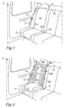
- Figures 2 and 3 illustrate an integrated booster cushion 1 in a child mode, wherein the rear seat 3 is adapted to receive a child.
- Figure 2 shows a perspective view and Figure 3 shows a side view.
- the integrated booster cushion 1 has been elevated to a vertically higher position than in the adult mode illustrated in Figure 1 .
- the integrated booster cushion 1 is positioned such that the same safety belt 9 can be used in the child mode, as in the adult mode of Figure 1 . Due to the higher vertical position, the safety belt 9 will fit properly to the body of the occupant of the booster cushion 1, e.g. a child or an adult of slight build.
- the child mode is suitable for use of occupants being in the range of from 90 cm to 150 cm.
- Figure 2 further illustrates two side impact protection devices 15a, 15b according to the invention, which are to be positioned at either side of the occupant when seated on the integrated booster cushion 1.
- the side impact protection devices 15a, 15b form a respective separate elongated body, i.e. they are not integrated in the rear seat 3.
- the side impact protection device 15a, 15b according to the invention may be used in existing vehicles, in particular in existing vehicles with integrated booster cushions, but they would also be useful together with a separate non-integrated booster cushion.
- the side impact protection devices 15a, 15b may be stored somewhere else, e.g. in the luggage compartment of the vehicle 5.
- the side impact protection devices 15a, 15b may be moved between different vehicles.
- Each side impact protection devices 15a, 15b is adapted to extend along a backrest 17 of the rear seat 3 from a first anchorage site 19a, 19b at or adjacent to an upper end of the backrest 17 to a second anchorage site 21 a, 21 b at or adjacent to a lower end of the backrest 17.
- the first anchorage site 19a, 19b comprises or is constituted by a top-tether anchorage site, which is configured to provide an attachment for the side impact protection devices 15a, 15b being able to withstand a force of a magnitude, which may arise in a collision involving the vehicle 5.
- the top-tether anchorage site 19a, 19b may be located at a trunk cover 22, as illustrated in Figure 3 , or at the rear side of the backrest 17 of the rear seat 3.
- the top-tether anchorage site 19a, 19b is further suitable for providing an upper anchorage site for attaching a child seat for infants or small children.
- the first anchorage site 19a, 19b may be provided by a headrest 24 of the rear seat 3.
- the second anchorage site 21 a, 21 b comprises or is constituted by an ISO fix anchorage site, which is suitable for providing a lower anchorage site for attaching a child seat for infants or small children.
- the second anchorage site 21 a, 21 b is configured to provide an attachment for the side impact protection devices 15a, 15b being able to withstand a force of a magnitude, which may arise in a collision involving the vehicle 5.
- the side impact protection device 15a, 15b has a first end portion with a first fastening element 23a, 23b adapted to be attached to the first anchorage site 19a, 19b, in the illustrated embodiment the top-tether anchorage site.
- the first end portion forms the upper end portion when the side impact protection device 15a, 15b is mounted in the vehicle seat 3.
- the first fastening element 23a, 23b may comprise a strap with a hook at the end, or a strap adapted to form a loop around or through the first anchorage site 19a, 19b, e.g. by being connected to itself by a buckle.
- the first fastening element 23a, 23b may have an adjustable length.
- the side impact protection device 15a, 15b further comprises a second end portion with a second fastening element 25a, 25b adapted to be attached to the second anchorage site 21 a, 21 b, in the illustrated embodiment, the respective ISO fix anchorage sites.
- the second end portion forms the lower end portion when the side impact protection device 15a, 15b is mounted in the vehicle seat 3.
- the second fastening element 25a, 25b may have an adjustable length.
- the second fastening element 25a, 25b is preferably configured to be strong enough to transfer an impact force arising in a collision situation to a body of the vehicle via the second anchorage site 21 a, 21 b.
- the second fastening element 25a, 25b may be rigid, e.g. made of metal.
- the first fastening element 23a, 23b and/or the second fastening element 25a, 25b is/are possible to tighten when the side impact protection device 15a, 15b is mounted in the vehicle seat 3 to reduce or avoid the risk that the side impact protection device 15a, 15b undesirably would move out of position in case of a side impact, e.g. a side collision.
- the side impact protection device 15a, 15b comprises a padded portion 27a, 27b adapted to extend all, or substantially all, the way along the backrest 17 between the first anchorage site 19a, 19b and the second anchorage site 21 a, 21 b.
- the padded portion 27a, 27b may comprise a padded metal frame with trim.
- the padding may comprise a foamed plastic and/or be inflatable.
- the padded portion 27a, 27b is preferably shaped and located such that it does not influence the function of the safety belt 9. It is preferred that the padded metal frame is strong enough to be able to withstand a force of a magnitude, which may arise in a collision involving the vehicle 5.
- the side impact protection devices 15a, 15b may be foldable in at least two parts. Further, if inflatable, the air may be possible to evacuate when the side impact protection device 15a, 15b is to be stored away.
- the side impact protection device 15a, 15b as well as its first fastening element 23a, 23b and second fastening element 25a, 25b are shaped such that the usual safety belt 9 can be used by the occupant sitting on the booster cushion 1.
- the side impact protection device 15a, 15b may in addition be provided with a safety belt guide, not illustrated, helping to place the safety belt 9 in a proper position in relation to the body of the occupant of the booster cushion.
- the illustrated embodiment discloses an integrated booster cushion 1 of a rear seat 3, it would also be possible to use the integrated booster cushion with corresponding side impact protection devices in a passenger front seat.
- the side impact protection device may be used in that mode as well and/or in one or more of the different positions.
- the booster cushion 1 with corresponding side impact protection devices 15a, 15b may be used in another vehicle, such as a bus, a tram or a train, and in a vessel, such as a ship or an aircraft.
Abstract
Description
- The present disclosure relates to a side impact protection device for a child sitting on a booster cushion in a vehicle seat. The disclosure further relates to an arrangement comprising at least one side impact protection device and the booster cushion and to a vehicle.
- When transporting a child in a vehicle, it is known to place the child on a booster cushion, which in turn is placed in a vehicle seat. Thereby, the seating position of the child is raised vertically, such that a safety belt of the vehicle will fit the child properly. A booster cushion may be used both in a front seat and in a rear seat, but it is often preferred to use the booster cushion in the rear seat.
- The booster cushion may be a separate cushion which is to be placed in the vehicle seat. As an alternative, the booster cushion may be integrated in the vehicle seat, e.g. in the rear seat. The integrated booster cushion may assume an adult mode, wherein the rear seat is adapted to receive an adult or a large child. In addition, the integrated booster cushion may assume a child mode adapted to receive a child and therefore the seat is located vertically higher than for the adult mode. It is also known to have an integrated booster cushion, which may assume a third mode, a small child mode, wherein the booster cushion is located vertically higher than for the child mode. It would also be possible to have an integrated booster cushion, which may assume a plurality of different vertical positions.
- Document
DE 10 2012 013451 A1 discloses an integrated booster cushion. Further, an inflatable air bag element is provided in a rear seat. The airbag element forms a side flange and/or a headrest for a child seat in an inflated condition. A compressor is provided for inflating the air bag element. - The air bag element of
DE 10 2012 013451 A1 could offer side impact protection for the child. However, the airbag element is integrated in the rear seat and can only be used together with the compressor. It would therefore be rather complicated, and hence expensive, to add such an airbag element to an existing vehicle, e.g. a vehicle with an existing integrated booster cushion. - Hence, there is a desire to provide an improved side impact protection device adapted for use together with a booster cushion.
- The object of the present disclosure is to overcome or ameliorate at least one of the disadvantages of the prior art, or to provide a useful alternative.
- The object above may be achieved by the subject-matter of
claim 1. Embodiments are set forth in the appended dependent claims, in the following description and in the drawings. - Thus, according to the invention there is provided a side impact protection device for a child sitting on a booster cushion in a vehicle seat. The side impact protection device comprises a separate elongated body having a first end portion with a first fastening element and a second end portion with a second fastening element. The side impact protection device is adapted to be mounted in a vehicle by means of the first and second fastening elements and to extend along a backrest of the vehicle seat with the first end portion and the first fastening element at a first anchorage site at an upper end of the backrest and with the second end portion and the second fastening element at a second anchorage site at a lower end of the backrest.
- The side impact protection device is utilized as a supplementary protection device. It is intended to be used together with a booster cushion. As mentioned above, the booster cushion may be a separate booster cushion, which is to be placed in the vehicle seat, or the booster cushion may be integrated in the vehicle seat. The side impact protection device and the booster cushion are suitable for use together with a safety belt of the vehicle. The booster cushion is positioned such that the same safety belt can be used in the child mode as in the adult mode. Due to the higher vertical position offered by the booster cushion, the safety belt will fit properly to the body of the occupant of the booster cushion, e.g. a child or an adult of slight build. The booster cushion may e.g. be suitable for use of occupants being in the range of from 90 cm to 150 cm.
- The side impact protection device being a separate body means that it is not integrated in the vehicle seat. Hence, the side impact protection device as described herein may be used in existing vehicles, in particular existing vehicles with integrated booster cushions, but they would also be useful together with a separate non-integrated booster cushion Further, when not in use, the side impact protection device may be stored somewhere else, e.g. in the luggage compartment. Moreover, the side impact protection device may be moved between different vehicles.
- The side impact protection device as described herein is adapted to be attached to the vehicle and/or to the vehicle seat by means of already existing anchorage sites located in the vehicle seat or the compartment of the vehicle, e.g. one or more anchorage sites adapted to attach a child seat for infants or small children. Alternatively, or additionally, the side impact protection device may be attached to another component of the vehicle seat or the vehicle body, such as a head rest or a body structure element. It is preferred that the attachment is strong enough to be able to withstand a force of a magnitude, which may arise in a collision involving the vehicle.
- The first fastening element may be adapted to be attached to a top-tether anchorage site, which is comprised in or constitutes the first anchorage site. The top-tether anchorage site may be located at a trunk cover or at a rear side of the backrest of the vehicle seat. The top-tether anchorage site is further also suitable for providing an upper anchorage site for attaching a child seat for infants or small children. As an alternative, or a complement, the first anchorage site may be provided by the headrest of the vehicle seat.
- The second fastening element may be adapted to be attached to an ISO fix anchorage site, which is comprised in or constitutes the second anchorage site. The ISO fix anchorage site is also suitable for providing a lower anchorage site for attaching a child seat for infants or small children.
- The elongated body may comprise a padded portion adapted to extend all, or substantially all, the way between the first fastening element and the second fastening element. The padded portion may comprise a padded metal frame with trim. The padding may comprise a foamed plastic and/or be inflatable. The padded portion is preferably shaped and located such that it does not influence the function of the safety belt. It is preferred that the padded metal frame is strong enough to be able to withstand a force of a magnitude, which may arise in a collision involving the vehicle.
- In order to facilitate storage when not in use, the side impact protection device, may be foldable in at least two parts. Further, if inflatable, the air may be possible to evacuate when the side impact protection device is to be stored away.
- The side impact protection device may be provided with a safety belt guide helping to place the safety belt in a proper position in relation to the body of the occupant of the booster cushion. The safety guide may be provided in the padded portion. The safety guide may comprise a slot or an aperture in the padded portion.
- The invention as described herein also relates to an arrangement comprising a booster cushion and at least one side impact protection device as described herein, preferably two side impact protection devices as described herein. Preferably, the booster cushion is adapted to be integrated in a vehicle seat. As mentioned above, the booster cushion may alternatively be a separate non-integrated booster cushion.
- The arrangement may further comprise the vehicle seat with the booster cushion being integrated into the vehicle seat. The vehicle seat is preferably a rear seat. However, it would also be possible to use the integrated booster cushion with corresponding side impact protection device or devices in a passenger front seat. In addition, the booster cushion with corresponding side impact protection devices may be used in another vehicle, such as a bus, a tram or a train, and in a vessel, such as a ship or an aircraft.
- The backrest of the vehicle seat may comprise the first anchorage site at or adjacent to the upper end of the backrest, the first anchorage site preferably comprising or being constituted by the top-tether anchorage site.
- The vehicle seat may comprise the second anchorage site at or adjacent to the lower end of the backrest, the second anchorage site preferably comprising or being constituted by the ISO fix anchorage site.
- The invention as described herein further relates to a vehicle comprising an arrangement as described herein.
- The present invention will hereinafter be further explained by means of non-limiting examples with reference to the appended drawings wherein:
- Fig. 1
- illustrates a perspective view of an integrated booster cushion of a rear seat of a vehicle in an adult mode,
- Fig. 2
- illustrates an arrangement comprising the integrated booster cushion of
Fig. 1 in a child mode together with two side impact protection devices according to the invention, and - Fig. 3
- illustrates a side view of the arrangement of
Fig. 2 . - It should be noted that the appended drawings are not necessarily drawn to scale and that the dimensions of some features of the present invention may have been exaggerated for the sake of clarity.
- The invention will, in the following, be exemplified by embodiments. It should however be realized that the embodiments are included in order to explain principles of the invention and not to limit the scope of the invention, as defined by the appended claims. Details from two or more of the embodiments may be combined with each other.
-
Figure 1 illustrates anintegrated booster cushion 1 of arear seat 3 of avehicle 5. Theintegrated booster cushion 1 is in an adult mode, wherein therear seat 3 is adapted to receive an adult or a large child. Thereby theintegrated booster cushion 1 is flush or substantially flush with the rest of a squab 7 of therear seat 3. There is further provided asafety belt 9, as commonly known in the art. Asafety belt attachment 11 is arranged to receive abuckle 13 of thesafety belt 9. -
Figures 2 and3 illustrate anintegrated booster cushion 1 in a child mode, wherein therear seat 3 is adapted to receive a child.Figure 2 shows a perspective view andFigure 3 shows a side view. - In the child mode of
Figures 2 and3 , theintegrated booster cushion 1 has been elevated to a vertically higher position than in the adult mode illustrated inFigure 1 . Theintegrated booster cushion 1 is positioned such that thesame safety belt 9 can be used in the child mode, as in the adult mode ofFigure 1 . Due to the higher vertical position, thesafety belt 9 will fit properly to the body of the occupant of thebooster cushion 1, e.g. a child or an adult of slight build. The child mode is suitable for use of occupants being in the range of from 90 cm to 150 cm. -
Figure 2 further illustrates two sideimpact protection devices integrated booster cushion 1. The sideimpact protection devices rear seat 3. Hence, the sideimpact protection device impact protection devices vehicle 5. Moreover, the sideimpact protection devices - Each side
impact protection devices backrest 17 of therear seat 3 from afirst anchorage site 19a, 19b at or adjacent to an upper end of thebackrest 17 to asecond anchorage site backrest 17. Thefirst anchorage site 19a, 19b comprises or is constituted by a top-tether anchorage site, which is configured to provide an attachment for the sideimpact protection devices vehicle 5. The top-tether anchorage site 19a, 19b may be located at atrunk cover 22, as illustrated inFigure 3 , or at the rear side of thebackrest 17 of therear seat 3. The top-tether anchorage site 19a, 19b is further suitable for providing an upper anchorage site for attaching a child seat for infants or small children. As an alternative, or a complement, thefirst anchorage site 19a, 19b may be provided by aheadrest 24 of therear seat 3. - The
second anchorage site second anchorage site impact protection devices vehicle 5. - The side
impact protection device first fastening element first anchorage site 19a, 19b, in the illustrated embodiment the top-tether anchorage site. The first end portion forms the upper end portion when the sideimpact protection device vehicle seat 3. Thefirst fastening element first anchorage site 19a, 19b, e.g. by being connected to itself by a buckle. Thefirst fastening element - The side
impact protection device second fastening element 25a, 25b adapted to be attached to thesecond anchorage site impact protection device vehicle seat 3. Thesecond fastening element 25a, 25b may have an adjustable length. Thesecond fastening element 25a, 25b is preferably configured to be strong enough to transfer an impact force arising in a collision situation to a body of the vehicle via thesecond anchorage site second fastening element 25a, 25b may be rigid, e.g. made of metal. - Preferably, the
first fastening element second fastening element 25a, 25b is/are possible to tighten when the sideimpact protection device vehicle seat 3 to reduce or avoid the risk that the sideimpact protection device - The side
impact protection device portion backrest 17 between thefirst anchorage site 19a, 19b and thesecond anchorage site portion portion safety belt 9. It is preferred that the padded metal frame is strong enough to be able to withstand a force of a magnitude, which may arise in a collision involving thevehicle 5. - In order to facilitate storage when not in use, the side
impact protection devices impact protection device - Preferably, the side
impact protection device first fastening element second fastening element 25a, 25b are shaped such that theusual safety belt 9 can be used by the occupant sitting on thebooster cushion 1. The sideimpact protection device safety belt 9 in a proper position in relation to the body of the occupant of the booster cushion. - Although the illustrated embodiment discloses an
integrated booster cushion 1 of arear seat 3, it would also be possible to use the integrated booster cushion with corresponding side impact protection devices in a passenger front seat. - For an integrated booster cushion also having the above-mentioned small child mode or plurality of different positions, the side impact protection device may be used in that mode as well and/or in one or more of the different positions.
- It would further be possible to use the side
impact protection devices - In addition, the
booster cushion 1 with corresponding sideimpact protection devices - Further modifications of the invention within the scope of the appended claims are feasible. As such, the present invention should not be considered as limited by the embodiments and figures described herein. Rather, the full scope of the invention should be determined by the appended claims, with reference to the description and drawings.
Claims (12)
- A side impact protection device (15a, 15b) for a child sitting on a booster cushion (1) in a vehicle seat (3),
said side impact protection device (15a, 15b) comprising a separate elongated body having a first end portion with a first fastening element (23a, 23b) and a second end portion with a second fastening element (25a, 25b),
said side impact protection device (15a, 15b) being adapted to be mounted in a vehicle (5) by means of said first (23a, 23b) and second (25a, 25b) fastening elements and to extend along a backrest (17) of said vehicle seat (3) with said first end portion and said first fastening element (23a, 23b) at a first anchorage site (19a, 19b) at an upper end of said backrest (17) and with said second end portion and said second fastening element (25a, 25b) at a second anchorage site (21 a, 21 b) at a lower end of said backrest (17). - The side impact protection device (15a, 15b) according to claim 1, wherein said first fastening element (23a, 23b) is adapted to be attached to a top-tether anchorage site (19a, 19b), which is comprised in or constitutes said first anchorage site.
- The side impact protection device (15a, 15b) according to claim 1 or 2 wherein said second fastening element (25a, 25b) is adapted to be attached to an ISO fix anchorage site (21 a, 21 b), which is comprised in or constitutes said second anchorage site.
- The side impact protection device (15a, 15b) according to any one of the preceding claims, wherein said elongated body comprises a padded portion (27a, 27b) adapted to extend all, or substantially all, the way between said first fastening element (23a, 23b) and said second fastening element (25a, 25b).
- The side impact protection device (15a, 15b) according to claim 4, wherein said padded portion (27a, 27b) comprises a padded metal frame with trim.
- The side impact protection device (15a, 15b) according to any one of the preceding claims being foldable in at least two parts.
- The side impact protection device (15a, 15b) according to any one of the preceding claims comprising a safety belt guide.
- An arrangement comprising a booster cushion (1) and at least one side impact protection device (15a, 15b) according to any one of the preceding claims, preferably two side impact protection devices (15a, 15b) according to any one of the preceding claims, preferably said booster cushion (1) being adapted to be integrated in a vehicle seat (3).
- The arrangement according to claim 8 further comprising said vehicle seat (3), said booster cushion (1) being integrated into said vehicle seat (3), said vehicle seat (3) preferably being a rear seat.
- The arrangement according to claim 9, wherein said backrest (17) of said vehicle seat (3) comprises said first anchorage site (19a, 19b) at or adjacent to said upper end of said backrest (17), said first anchorage site (19a, 19b) preferably comprising or being constituted by said top-tether anchorage site.
- The arrangement according to claim 9 or 10, wherein said vehicle seat (3) comprises said second anchorage site (21 a, 21 b) at or adjacent to said lower end of said backrest (17), said second anchorage site (21 a, 21 b) preferably comprising or being constituted by said ISO fix anchorage site.
- A vehicle (5) comprising an arrangement according to any one of claims 8-11.
Priority Applications (1)
| Application Number | Priority Date | Filing Date | Title |
|---|---|---|---|
| EP16159888.3A EP3216646B1 (en) | 2016-03-11 | 2016-03-11 | Side impact protection device |
Applications Claiming Priority (1)
| Application Number | Priority Date | Filing Date | Title |
|---|---|---|---|
| EP16159888.3A EP3216646B1 (en) | 2016-03-11 | 2016-03-11 | Side impact protection device |
Publications (2)
| Publication Number | Publication Date |
|---|---|
| EP3216646A1 true EP3216646A1 (en) | 2017-09-13 |
| EP3216646B1 EP3216646B1 (en) | 2018-12-12 |
Family
ID=55527411
Family Applications (1)
| Application Number | Title | Priority Date | Filing Date |
|---|---|---|---|
| EP16159888.3A Active EP3216646B1 (en) | 2016-03-11 | 2016-03-11 | Side impact protection device |
Country Status (1)
| Country | Link |
|---|---|
| EP (1) | EP3216646B1 (en) |
Cited By (1)
| Publication number | Priority date | Publication date | Assignee | Title |
|---|---|---|---|---|
| CN115056687A (en) * | 2018-02-02 | 2022-09-16 | 宝钜瑞士股份有限公司 | Automatic-ejecting side-impact protection device |
Citations (2)
| Publication number | Priority date | Publication date | Assignee | Title |
|---|---|---|---|---|
| DE10258245A1 (en) * | 2002-12-13 | 2004-06-24 | Volkswagen Ag | Child safety device for automobile provided by side restraint folded out from stowed position into working position limiting sidewards movement of child |
| DE102012013451A1 (en) | 2012-07-05 | 2014-01-09 | Daimler Ag | Motor car, has inflatable air bag element provided in back of motor car seat that forms side flange and/or headrest for child seat in inflated condition, and compressor provided for inflating air bag element |
-
2016
- 2016-03-11 EP EP16159888.3A patent/EP3216646B1/en active Active
Patent Citations (2)
| Publication number | Priority date | Publication date | Assignee | Title |
|---|---|---|---|---|
| DE10258245A1 (en) * | 2002-12-13 | 2004-06-24 | Volkswagen Ag | Child safety device for automobile provided by side restraint folded out from stowed position into working position limiting sidewards movement of child |
| DE102012013451A1 (en) | 2012-07-05 | 2014-01-09 | Daimler Ag | Motor car, has inflatable air bag element provided in back of motor car seat that forms side flange and/or headrest for child seat in inflated condition, and compressor provided for inflating air bag element |
Cited By (2)
| Publication number | Priority date | Publication date | Assignee | Title |
|---|---|---|---|---|
| CN115056687A (en) * | 2018-02-02 | 2022-09-16 | 宝钜瑞士股份有限公司 | Automatic-ejecting side-impact protection device |
| CN115056687B (en) * | 2018-02-02 | 2024-02-02 | 宝钜瑞士股份有限公司 | Automatic pop-up side-impact protection device |
Also Published As
| Publication number | Publication date |
|---|---|
| EP3216646B1 (en) | 2018-12-12 |
Similar Documents
| Publication | Publication Date | Title |
|---|---|---|
| JP5261388B2 (en) | Seat belt retaining device and system | |
| US20200114858A1 (en) | Air bag device and vehicle seat provided with an air bag device | |
| US6871876B2 (en) | Seat belt restraint system with double shoulder belts | |
| US6846020B2 (en) | Seat belt restraint system for both adults and children | |
| US5511850A (en) | Child's automobile safety seat | |
| EP2414190B1 (en) | Booster cushion for use with a vehicle seat | |
| US7264275B2 (en) | Occupant restraint system | |
| US20180022241A1 (en) | Portable Child Safety Seat with Five-Point Restraint | |
| KR20160014634A (en) | Shaped airbag | |
| US20040140660A1 (en) | Seat belt restraint system with lap belt adjustment device | |
| JP6525254B2 (en) | Vehicle seat | |
| US20200307488A1 (en) | Seat assembly with full seatback airbag | |
| US11167714B2 (en) | Occupant restraint system for a vehicle | |
| US20170050611A1 (en) | Child restraint system for use in vehicles | |
| US6692020B2 (en) | Safety device for protection of a passenger of a motor vehicle, comprising a seat belt and associated inflatable air bag | |
| US9840173B2 (en) | Removable vehicle seating | |
| US9010863B2 (en) | Bus seating system | |
| US9676305B2 (en) | Vehicle seat with integrated child seat | |
| EP3216646B1 (en) | Side impact protection device | |
| CN111086422B (en) | Collapsible restraint device releasably attachable to a main support structure of a vehicle | |
| CN105799633B (en) | Vehicle seat with an airbag module arranged in the seat part | |
| US10632870B1 (en) | Integrated child seat upper harness attachment and routing methods | |
| JP6418121B2 (en) | Retractor mounting structure | |
| KR101697920B1 (en) | A side airbag apparatus | |
| CN219236973U (en) | A first chest gasbag protection system for vehicle seat |
Legal Events
| Date | Code | Title | Description |
|---|---|---|---|
| PUAI | Public reference made under article 153(3) epc to a published international application that has entered the european phase |
Free format text: ORIGINAL CODE: 0009012 |
|
| STAA | Information on the status of an ep patent application or granted ep patent |
Free format text: STATUS: THE APPLICATION HAS BEEN PUBLISHED |
|
| AK | Designated contracting states |
Kind code of ref document: A1 Designated state(s): AL AT BE BG CH CY CZ DE DK EE ES FI FR GB GR HR HU IE IS IT LI LT LU LV MC MK MT NL NO PL PT RO RS SE SI SK SM TR |
|
| AX | Request for extension of the european patent |
Extension state: BA ME |
|
| STAA | Information on the status of an ep patent application or granted ep patent |
Free format text: STATUS: REQUEST FOR EXAMINATION WAS MADE |
|
| 17P | Request for examination filed |
Effective date: 20180313 |
|
| RBV | Designated contracting states (corrected) |
Designated state(s): AL AT BE BG CH CY CZ DE DK EE ES FI FR GB GR HR HU IE IS IT LI LT LU LV MC MK MT NL NO PL PT RO RS SE SI SK SM TR |
|
| GRAP | Despatch of communication of intention to grant a patent |
Free format text: ORIGINAL CODE: EPIDOSNIGR1 |
|
| STAA | Information on the status of an ep patent application or granted ep patent |
Free format text: STATUS: GRANT OF PATENT IS INTENDED |
|
| INTG | Intention to grant announced |
Effective date: 20180731 |
|
| GRAS | Grant fee paid |
Free format text: ORIGINAL CODE: EPIDOSNIGR3 |
|
| GRAA | (expected) grant |
Free format text: ORIGINAL CODE: 0009210 |
|
| STAA | Information on the status of an ep patent application or granted ep patent |
Free format text: STATUS: THE PATENT HAS BEEN GRANTED |
|
| AK | Designated contracting states |
Kind code of ref document: B1 Designated state(s): AL AT BE BG CH CY CZ DE DK EE ES FI FR GB GR HR HU IE IS IT LI LT LU LV MC MK MT NL NO PL PT RO RS SE SI SK SM TR |
|
| REG | Reference to a national code |
Ref country code: GB Ref legal event code: FG4D |
|
| REG | Reference to a national code |
Ref country code: CH Ref legal event code: EP |
|
| REG | Reference to a national code |
Ref country code: AT Ref legal event code: REF Ref document number: 1075495 Country of ref document: AT Kind code of ref document: T Effective date: 20181215 |
|
| REG | Reference to a national code |
Ref country code: DE Ref legal event code: R096 Ref document number: 602016007946 Country of ref document: DE |
|
| REG | Reference to a national code |
Ref country code: IE Ref legal event code: FG4D |
|
| REG | Reference to a national code |
Ref country code: NL Ref legal event code: MP Effective date: 20181212 |
|
| REG | Reference to a national code |
Ref country code: LT Ref legal event code: MG4D |
|
| PG25 | Lapsed in a contracting state [announced via postgrant information from national office to epo] |
Ref country code: FI Free format text: LAPSE BECAUSE OF FAILURE TO SUBMIT A TRANSLATION OF THE DESCRIPTION OR TO PAY THE FEE WITHIN THE PRESCRIBED TIME-LIMIT Effective date: 20181212 Ref country code: BG Free format text: LAPSE BECAUSE OF FAILURE TO SUBMIT A TRANSLATION OF THE DESCRIPTION OR TO PAY THE FEE WITHIN THE PRESCRIBED TIME-LIMIT Effective date: 20190312 Ref country code: HR Free format text: LAPSE BECAUSE OF FAILURE TO SUBMIT A TRANSLATION OF THE DESCRIPTION OR TO PAY THE FEE WITHIN THE PRESCRIBED TIME-LIMIT Effective date: 20181212 Ref country code: LT Free format text: LAPSE BECAUSE OF FAILURE TO SUBMIT A TRANSLATION OF THE DESCRIPTION OR TO PAY THE FEE WITHIN THE PRESCRIBED TIME-LIMIT Effective date: 20181212 Ref country code: NO Free format text: LAPSE BECAUSE OF FAILURE TO SUBMIT A TRANSLATION OF THE DESCRIPTION OR TO PAY THE FEE WITHIN THE PRESCRIBED TIME-LIMIT Effective date: 20190312 Ref country code: ES Free format text: LAPSE BECAUSE OF FAILURE TO SUBMIT A TRANSLATION OF THE DESCRIPTION OR TO PAY THE FEE WITHIN THE PRESCRIBED TIME-LIMIT Effective date: 20181212 Ref country code: LV Free format text: LAPSE BECAUSE OF FAILURE TO SUBMIT A TRANSLATION OF THE DESCRIPTION OR TO PAY THE FEE WITHIN THE PRESCRIBED TIME-LIMIT Effective date: 20181212 |
|
| REG | Reference to a national code |
Ref country code: AT Ref legal event code: MK05 Ref document number: 1075495 Country of ref document: AT Kind code of ref document: T Effective date: 20181212 |
|
| PG25 | Lapsed in a contracting state [announced via postgrant information from national office to epo] |
Ref country code: SE Free format text: LAPSE BECAUSE OF FAILURE TO SUBMIT A TRANSLATION OF THE DESCRIPTION OR TO PAY THE FEE WITHIN THE PRESCRIBED TIME-LIMIT Effective date: 20181212 Ref country code: AL Free format text: LAPSE BECAUSE OF FAILURE TO SUBMIT A TRANSLATION OF THE DESCRIPTION OR TO PAY THE FEE WITHIN THE PRESCRIBED TIME-LIMIT Effective date: 20181212 Ref country code: RS Free format text: LAPSE BECAUSE OF FAILURE TO SUBMIT A TRANSLATION OF THE DESCRIPTION OR TO PAY THE FEE WITHIN THE PRESCRIBED TIME-LIMIT Effective date: 20181212 Ref country code: GR Free format text: LAPSE BECAUSE OF FAILURE TO SUBMIT A TRANSLATION OF THE DESCRIPTION OR TO PAY THE FEE WITHIN THE PRESCRIBED TIME-LIMIT Effective date: 20190313 |
|
| PG25 | Lapsed in a contracting state [announced via postgrant information from national office to epo] |
Ref country code: NL Free format text: LAPSE BECAUSE OF FAILURE TO SUBMIT A TRANSLATION OF THE DESCRIPTION OR TO PAY THE FEE WITHIN THE PRESCRIBED TIME-LIMIT Effective date: 20181212 |
|
| PG25 | Lapsed in a contracting state [announced via postgrant information from national office to epo] |
Ref country code: PL Free format text: LAPSE BECAUSE OF FAILURE TO SUBMIT A TRANSLATION OF THE DESCRIPTION OR TO PAY THE FEE WITHIN THE PRESCRIBED TIME-LIMIT Effective date: 20181212 Ref country code: CZ Free format text: LAPSE BECAUSE OF FAILURE TO SUBMIT A TRANSLATION OF THE DESCRIPTION OR TO PAY THE FEE WITHIN THE PRESCRIBED TIME-LIMIT Effective date: 20181212 Ref country code: PT Free format text: LAPSE BECAUSE OF FAILURE TO SUBMIT A TRANSLATION OF THE DESCRIPTION OR TO PAY THE FEE WITHIN THE PRESCRIBED TIME-LIMIT Effective date: 20190412 |
|
| PG25 | Lapsed in a contracting state [announced via postgrant information from national office to epo] |
Ref country code: EE Free format text: LAPSE BECAUSE OF FAILURE TO SUBMIT A TRANSLATION OF THE DESCRIPTION OR TO PAY THE FEE WITHIN THE PRESCRIBED TIME-LIMIT Effective date: 20181212 Ref country code: RO Free format text: LAPSE BECAUSE OF FAILURE TO SUBMIT A TRANSLATION OF THE DESCRIPTION OR TO PAY THE FEE WITHIN THE PRESCRIBED TIME-LIMIT Effective date: 20181212 Ref country code: IS Free format text: LAPSE BECAUSE OF FAILURE TO SUBMIT A TRANSLATION OF THE DESCRIPTION OR TO PAY THE FEE WITHIN THE PRESCRIBED TIME-LIMIT Effective date: 20190412 Ref country code: SK Free format text: LAPSE BECAUSE OF FAILURE TO SUBMIT A TRANSLATION OF THE DESCRIPTION OR TO PAY THE FEE WITHIN THE PRESCRIBED TIME-LIMIT Effective date: 20181212 Ref country code: SM Free format text: LAPSE BECAUSE OF FAILURE TO SUBMIT A TRANSLATION OF THE DESCRIPTION OR TO PAY THE FEE WITHIN THE PRESCRIBED TIME-LIMIT Effective date: 20181212 |
|
| REG | Reference to a national code |
Ref country code: DE Ref legal event code: R097 Ref document number: 602016007946 Country of ref document: DE |
|
| PLBE | No opposition filed within time limit |
Free format text: ORIGINAL CODE: 0009261 |
|
| STAA | Information on the status of an ep patent application or granted ep patent |
Free format text: STATUS: NO OPPOSITION FILED WITHIN TIME LIMIT |
|
| PG25 | Lapsed in a contracting state [announced via postgrant information from national office to epo] |
Ref country code: DK Free format text: LAPSE BECAUSE OF FAILURE TO SUBMIT A TRANSLATION OF THE DESCRIPTION OR TO PAY THE FEE WITHIN THE PRESCRIBED TIME-LIMIT Effective date: 20181212 Ref country code: AT Free format text: LAPSE BECAUSE OF FAILURE TO SUBMIT A TRANSLATION OF THE DESCRIPTION OR TO PAY THE FEE WITHIN THE PRESCRIBED TIME-LIMIT Effective date: 20181212 Ref country code: SI Free format text: LAPSE BECAUSE OF FAILURE TO SUBMIT A TRANSLATION OF THE DESCRIPTION OR TO PAY THE FEE WITHIN THE PRESCRIBED TIME-LIMIT Effective date: 20181212 Ref country code: MC Free format text: LAPSE BECAUSE OF FAILURE TO SUBMIT A TRANSLATION OF THE DESCRIPTION OR TO PAY THE FEE WITHIN THE PRESCRIBED TIME-LIMIT Effective date: 20181212 |
|
| REG | Reference to a national code |
Ref country code: CH Ref legal event code: PL |
|
| 26N | No opposition filed |
Effective date: 20190913 |
|
| PG25 | Lapsed in a contracting state [announced via postgrant information from national office to epo] |
Ref country code: LU Free format text: LAPSE BECAUSE OF NON-PAYMENT OF DUE FEES Effective date: 20190311 |
|
| REG | Reference to a national code |
Ref country code: BE Ref legal event code: MM Effective date: 20190331 |
|
| PG25 | Lapsed in a contracting state [announced via postgrant information from national office to epo] |
Ref country code: IE Free format text: LAPSE BECAUSE OF NON-PAYMENT OF DUE FEES Effective date: 20190311 Ref country code: LI Free format text: LAPSE BECAUSE OF NON-PAYMENT OF DUE FEES Effective date: 20190331 Ref country code: CH Free format text: LAPSE BECAUSE OF NON-PAYMENT OF DUE FEES Effective date: 20190331 |
|
| PG25 | Lapsed in a contracting state [announced via postgrant information from national office to epo] |
Ref country code: BE Free format text: LAPSE BECAUSE OF NON-PAYMENT OF DUE FEES Effective date: 20190331 |
|
| PG25 | Lapsed in a contracting state [announced via postgrant information from national office to epo] |
Ref country code: TR Free format text: LAPSE BECAUSE OF FAILURE TO SUBMIT A TRANSLATION OF THE DESCRIPTION OR TO PAY THE FEE WITHIN THE PRESCRIBED TIME-LIMIT Effective date: 20181212 |
|
| PG25 | Lapsed in a contracting state [announced via postgrant information from national office to epo] |
Ref country code: MT Free format text: LAPSE BECAUSE OF NON-PAYMENT OF DUE FEES Effective date: 20190311 |
|
| GBPC | Gb: european patent ceased through non-payment of renewal fee |
Effective date: 20200311 |
|
| PG25 | Lapsed in a contracting state [announced via postgrant information from national office to epo] |
Ref country code: GB Free format text: LAPSE BECAUSE OF NON-PAYMENT OF DUE FEES Effective date: 20200311 |
|
| PG25 | Lapsed in a contracting state [announced via postgrant information from national office to epo] |
Ref country code: CY Free format text: LAPSE BECAUSE OF FAILURE TO SUBMIT A TRANSLATION OF THE DESCRIPTION OR TO PAY THE FEE WITHIN THE PRESCRIBED TIME-LIMIT Effective date: 20181212 |
|
| PG25 | Lapsed in a contracting state [announced via postgrant information from national office to epo] |
Ref country code: HU Free format text: LAPSE BECAUSE OF FAILURE TO SUBMIT A TRANSLATION OF THE DESCRIPTION OR TO PAY THE FEE WITHIN THE PRESCRIBED TIME-LIMIT; INVALID AB INITIO Effective date: 20160311 |
|
| PG25 | Lapsed in a contracting state [announced via postgrant information from national office to epo] |
Ref country code: MK Free format text: LAPSE BECAUSE OF FAILURE TO SUBMIT A TRANSLATION OF THE DESCRIPTION OR TO PAY THE FEE WITHIN THE PRESCRIBED TIME-LIMIT Effective date: 20181212 |
|
| PGFP | Annual fee paid to national office [announced via postgrant information from national office to epo] |
Ref country code: FR Payment date: 20230222 Year of fee payment: 8 |
|
| PGFP | Annual fee paid to national office [announced via postgrant information from national office to epo] |
Ref country code: IT Payment date: 20230221 Year of fee payment: 8 Ref country code: DE Payment date: 20230221 Year of fee payment: 8 |
|
| P01 | Opt-out of the competence of the unified patent court (upc) registered |
Effective date: 20231212 |