EP3216637A1 - Drive cable having a plastics cable body - Google Patents
Drive cable having a plastics cable body Download PDFInfo
- Publication number
- EP3216637A1 EP3216637A1 EP16158982.5A EP16158982A EP3216637A1 EP 3216637 A1 EP3216637 A1 EP 3216637A1 EP 16158982 A EP16158982 A EP 16158982A EP 3216637 A1 EP3216637 A1 EP 3216637A1
- Authority
- EP
- European Patent Office
- Prior art keywords
- cable
- armouring
- coupling element
- drive
- drive cable
- Prior art date
- Legal status (The legal status is an assumption and is not a legal conclusion. Google has not performed a legal analysis and makes no representation as to the accuracy of the status listed.)
- Granted
Links
Images


Classifications
-
- B—PERFORMING OPERATIONS; TRANSPORTING
- B60—VEHICLES IN GENERAL
- B60J—WINDOWS, WINDSCREENS, NON-FIXED ROOFS, DOORS, OR SIMILAR DEVICES FOR VEHICLES; REMOVABLE EXTERNAL PROTECTIVE COVERINGS SPECIALLY ADAPTED FOR VEHICLES
- B60J7/00—Non-fixed roofs; Roofs with movable panels, e.g. rotary sunroofs
- B60J7/02—Non-fixed roofs; Roofs with movable panels, e.g. rotary sunroofs of sliding type, e.g. comprising guide shoes
- B60J7/04—Non-fixed roofs; Roofs with movable panels, e.g. rotary sunroofs of sliding type, e.g. comprising guide shoes with rigid plate-like element or elements, e.g. open roofs with harmonica-type folding rigid panels
- B60J7/057—Driving or actuating arrangements e.g. manually operated levers or knobs
- B60J7/0573—Driving or actuating arrangements e.g. manually operated levers or knobs power driven arrangements, e.g. electrical
-
- B—PERFORMING OPERATIONS; TRANSPORTING
- B60—VEHICLES IN GENERAL
- B60J—WINDOWS, WINDSCREENS, NON-FIXED ROOFS, DOORS, OR SIMILAR DEVICES FOR VEHICLES; REMOVABLE EXTERNAL PROTECTIVE COVERINGS SPECIALLY ADAPTED FOR VEHICLES
- B60J7/00—Non-fixed roofs; Roofs with movable panels, e.g. rotary sunroofs
- B60J7/02—Non-fixed roofs; Roofs with movable panels, e.g. rotary sunroofs of sliding type, e.g. comprising guide shoes
-
- F—MECHANICAL ENGINEERING; LIGHTING; HEATING; WEAPONS; BLASTING
- F16—ENGINEERING ELEMENTS AND UNITS; GENERAL MEASURES FOR PRODUCING AND MAINTAINING EFFECTIVE FUNCTIONING OF MACHINES OR INSTALLATIONS; THERMAL INSULATION IN GENERAL
- F16C—SHAFTS; FLEXIBLE SHAFTS; ELEMENTS OR CRANKSHAFT MECHANISMS; ROTARY BODIES OTHER THAN GEARING ELEMENTS; BEARINGS
- F16C1/00—Flexible shafts; Mechanical means for transmitting movement in a flexible sheathing
- F16C1/10—Means for transmitting linear movement in a flexible sheathing, e.g. "Bowden-mechanisms"
- F16C1/12—Arrangements for transmitting movement to or from the flexible member
- F16C1/16—Arrangements for transmitting movement to or from the flexible member in which the end-piece is guided rectilinearly
-
- F—MECHANICAL ENGINEERING; LIGHTING; HEATING; WEAPONS; BLASTING
- F16—ENGINEERING ELEMENTS AND UNITS; GENERAL MEASURES FOR PRODUCING AND MAINTAINING EFFECTIVE FUNCTIONING OF MACHINES OR INSTALLATIONS; THERMAL INSULATION IN GENERAL
- F16C—SHAFTS; FLEXIBLE SHAFTS; ELEMENTS OR CRANKSHAFT MECHANISMS; ROTARY BODIES OTHER THAN GEARING ELEMENTS; BEARINGS
- F16C2326/00—Articles relating to transporting
- F16C2326/01—Parts of vehicles in general
Definitions
- the invention relates to a drive cable for actuating a structural element being movable as against a structure, having the features of the preamble of claim 1.
- Drive cables of this kind are known from practice and serve to actuate, for example in the context of a motor vehicle, a lid element of a sliding roof arrangement, which lid element constitutes a movable structural element and with the aid of which a roof opening of the relevant vehicle may selectively be closed or at the very least partially be cleared.
- the drive cable transmits a drive force from a drive motor onto the lid element and comprises a cable body which is made of plastics, and is provided with an armouring. The armouring reaches through the cable body in the axial direction thereof.
- a denticulation is realised which extends in the axial direction, and which serves to engage a mating denticulation formed by a driving wheel of the drive motor.
- the armouring gives the needed stability to the drive cable.
- a drive cable for actuating an element being movable with respect to a structure, comprising a cable body which is made of one or more plastics and which comprises a denticulation extending in the axial direction for engaging a mating denticulation as well as at least one armouring, which continuously reaches through the cable body in the axial direction.
- the drive cable includes a coupling element which is realised as a moulded section, and which is moulded in a cable connecting region so as to adjoin the cable body and includes a coupling portion for being coupled to the moveable element.
- the drive cable according to the invention thus includes a moulded portion, manufactured in the connecting region of the cable according to a moulding method, in particular to an injection moulding method, and adjoining the cable body.
- the moulded portion formed by the coupling element defines the overmoulded length of the cable.
- the coupling element includes a coupling portion, which may for example project in relation to the axis of the drive cable in the radial direction, from a joining portion or support portion, whose peripheral face is preferably flush with the peripheral face of the cable body.
- the coupling element may directly be guided in a guide track of a guide rail, in which the drive cable is also guided.
- the connecting region of the cable is the region of the cable, where it is coupled to the moveable element to be driven, and may be an end region of the cable.
- the connecting region may be any other region along the cable suitable for coupling it to the moveable element to be driven.
- the coupling element reaches around the armouring, wherein it is directly moulded onto the same.
- directly joining the coupling element to the armouring that means in a cable region free of the cable body, high peel or racking forces may be realised, that means it is possible to connect the coupling element to the drive cable so fixedly that it does not even get detached from the drive cable or from the cable body under high forces.
- high forces are for example forces that are higher than half of the breaking load of the drive cable.
- an anchor element is provided for anchoring the coupling element to the armouring of the drive cable.
- the position of the coupling element is also securely kept up as against the cable body when large forces act in the axial direction of the cable.
- the anchor element By the anchor element, the contact surface between the coupling element and the armouring is increased.
- the anchor element for the coupling element may be realised in different manners.
- a deformed armouring portion forms the anchor element or the anchor element may also be a separate piece fixed to the armouring.
- Combinations of the different anchor elements are also conceivable.
- a deformed armouring portion for forming the anchor element may for example be realised by an armouring loop, by one or more kinks or bends of the armouring or by a knot of the armouring.
- the deformed armouring portion being projected in the longitudinal direction of the cable, for enlarging the contact face between the coupling element and the armouring and hence for forming the anchor element, may be outside of the cross-section of the cable body, wherein it is always embedded into the coupling element.
- the armouring of the drive cable comprises one or more wires of filaments twisted together.
- an anchor element for the coupling element can conveniently formed.
- the anchor element can also be formed by untwisting and fanning out the filaments at the wire end thereby forming the anchor element.
- An anchor element that is realised as a separate piece is, for example, a crimp sleeve or a tab, which has a special shape and extends in the radial direction in relation to the axis of the armouring.
- the anchor element may be formed by a connecting region of two armouring harnesses.
- the two armouring harnesses are knotted for this purpose.
- an annular-collar-like portion of the cable body forms the anchor element, an armouring portion abutting on said portion in the longitudinal direction of the cable, and the coupling element directly being moulded onto the armouring portion.
- the cable body Before moulding the coupling element onto the armouring portion, the cable body, in this embodiment, is removed in a portion spaced apart from the cable end, such that the coupling element may get caught at the remaining end-side and annular-collar-like portion of the cable body.
- the coupling element is directly moulded onto the periphery of the cable body.
- the cable body in the region of joining for the coupling element, includes a structured anchor surface for the coupling element.
- the anchor face is, for example, realised by a roughening or ribbing of the periphery of the cable body or also by the denticulation.
- the structured anchor surface which may be generated by working the plastics of the cable body, makes additional anchor forces for the coupling element available, such that the coupling element may also withstand high tensile forces.
- the drive cable according to the invention is in particular a drive cable for a movable roof element of a motor vehicle.
- the drive cable with its coupling element, may be joined to a drive slide of a sliding roof mechanism of a motor vehicle or also to a shading system of a vehicle roof.
- Subject-matter of the invention is also a tool for moulding a coupling element being realised as an injection moulded section to a drive cable, which serves to actuate a structural element being movable as against a structure and comprises a cable body which is made of plastics, and which includes a denticulation extending in the axial direction for engaging a mating denticulation as well as at least one armouring, which continuously reaches through the cable body in the axial direction.
- the tool comprises a tool mould having a mould cavity, which corresponds to the coupling element and includes an opening, via which the drive cable can be introduced into the mould cavity and whose cross section is designed according to the cross section of the cable body.
- the diameter of the opening is smaller than the diameter of the cable body, so that the plastics of the cable body is used for sealing the mould cavity in the region of the opening, to be more precise in such a manner that the tool mould wall, in which the opening is realised, engages the plastics or the polymer of the cable body in the closed position of the tool mould, in this way sealing the mould cavity.
- the opening is in particular a sealing-free opening, so that the opening comprises no wearing part.
- the tool mould preferably has a holding element for the armouring of the drive cable.
- the armouring thus takes up a defined position during the injection moulding process carried out with the help of the tool.
- the tool mould includes a deforming arrangement for the armouring of the drive cable.
- pins, ribs or lands form the deforming arrangement, which engage the mould cavity.
- the pins, ribs or lands function in such a manner that contact is established between them and the armouring freed from the cable body when the tool mould, which is usually built up of two shells, is being closed, kinking or bending the armouring, whereby an anchor portion or an anchor element is formed.
- deformation of the armouring to increase the mechanical anchoring in the overmoulded part of the cable formed by the coupling element can be formed during closing operation of the mould. No additional process steps are needed for deforming the anchor element.
- the tool mould in a preferred embodiment, includes a mating denticulation or negative profile, which engages the denticulation of the cable body when the drive cable engages the mould cavity.
- the denticulation of the cable is used for proper orientation of the cable in the overmoulding tool.
- alternative means for defined orientation of the cable in the mould are conceivable. Such a positioning means ensures the correct orientation of the cable in the mould with no additional effort, so that misalignment is avoided. Further, by the defined positioning of the cable in the mould, a defmed peel and racking force for the cable and a defined overmoulded length are given.
- the mating denticulation may be realised at a pinion or a slider of the tool mould, which is used for supplying and/or for removing the drive cable in or from the mould cavity and which may automatically operate.
- the slider can be provided with a driving unit.
- a vehicle roof 10 which is part of a passenger car not being illustrated otherwise, and which includes a roof opening 12, which may selectively be closed or at the very least partially be cleared with the aid of a lid element 14.
- the lid element 14 thus constitutes a vehicle element, which is movable as against the vehicle structure and is part of a roof opening system.
- the roof opening system includes displacing kinematics, which, in relation to a vertical longitudinal centre plane of the roof on each of their two sides, include a drive slide 16A or 16B, which is guided in a respective guide rail 18A or 18B extending in the longitudinal direction of the roof.
- a drive cable 20 that is rigid in compression and tension is connected to each drive slide 16A, 16B via a respective coupling element 22, which is formed from a plastics injection moulded section of the respective drive cable 20 and is connected to the respective drive slide 16A or 16B.
- the drive cables 20 are guided to a common drive motor 24 via corresponding guide channels and engage with a common toothed driving wheel 26 of the drive motor 24.
- the drive cables 20, which are illustrated in a detailed fashion using Figures 2 to 5 , and are guided in a respective guide channel 28 of the relevant guide rail 18A or 18B for the drive slides 16A and 16B, are each realised as plastics drive cable and each include a substantially cylindrical cable body 30 which is made of a bendable plastics material, and which, at the periphery, is provided with a denticulation 32, which extends in the axial direction of the drive cable 20 and is realised for engaging the toothed driving wheel 26 that forms a mating denticulation.
- the denticulation of the drive cable 20 assigned to drive slide 16A is arranged on the side of the cable body 30 facing away from the roof opening 12, whereas the denticulation 32 of the drive cable 20 assigned to drive slide 16B is arranged on the side of the cable body 30 facing the roof opening 12.
- Each of the drive cables 20 is moreover provided with an armouring 34, which is formed from a steel wire strand in the present case and reaches through the cable body 30 in the axial direction.
- the armouring 34 may also be made from another axially stiff and bendable material.
- each of the drive cables 20 is provided with the coupling element 22 for being connected to the respective drive slide 16A or 16B.
- An injection moulded section which is made of a plastics material forms the coupling element 22, which adjoins the cable body 32 with a joining portion 38.
- the joining portion 38 has a peripheral face or mantle, which is flush with the peripheral face of the cable body 30, such that the coupling element 22 may be guided in the guide channel 28 of the relevant guide rail 18A or 18B, together with the cable body 30.
- a connecting portion 40 in the manner of a tab projects from the joining portion 38 in the direction of the respective drive slides 16A or 16B.
- the connecting portion 40 has an at least nearly L-shaped cross-section for connecting to the respective drive slide.
- the armouring 34 which is guided out of the cable body 30 into the coupling element 22, forms an internal anchor element 42, which is formed from an end portion of the armouring 34 having been bent several times and initially extends, starting from the cable body 30, in the joining portion 38 and then through the connecting portion 40 close to the face side of the coupling element 22.
- an internal anchor element 42 which is formed from an end portion of the armouring 34 having been bent several times and initially extends, starting from the cable body 30, in the joining portion 38 and then through the connecting portion 40 close to the face side of the coupling element 22.
- FIG 6 an alternative embodiment of a drive cable 20 is illustrated, serving to drive a sliding roof lid of the type that is illustrated in Figure 1 and comprising a cable body 30, in correspondence with the embodiment according to Figures 2 to 5 , which is provided with a denticulation and through which an armouring 34 reaches in the axial direction.
- the armouring 34 leaves the cable body 30, that means the cable body 30 is removed in the cable end portion 36.
- a coupling element 22 is moulded onto the armouring 34 in a direct manner, said coupling element being realised as a plastics injection moulded section and including a joining portion 38, which reaches around the armouring 34 and whose periphery/mantle is flush with the periphery of the cable body 30.
- a connecting portion 40 being illustrated in dashed lines in the drawing projects, in relation to the axis of the cable 20 in the transverse direction or radial direction, from the joining portion 38, which adjoins the cable body 30, the drive cable 20 being able to be joined to a drive slide of the roof opening mechanism via said connecting portion 40.
- the armouring 34 forms the anchoring for the coupling element 22.
- FIG. 7 another embodiment of a drive cable 20 is illustrated, which largely corresponds to the embodiment according to Figure 6 , but differs from the same in that it includes two armourings 34 each of which constitutes an armouring harness, and which are freed from a cable body 30 in a cable end region 3, but around which a coupling element 22 with the joining portion 38 thereof reaches.
- the drive cable 20 in accordance with Figure 7 corresponds to the drive cable according to Figure 6 .
- drive cables 20 are in each instance illustrated, formed from a cable body 30, in correspondence with the aforedescribed embodiments, said cable body being provided, over at least part of its periphery, with a denticulation extending in the longitudinal direction of the cable for engaging a toothed driving wheel of a drive motor.
- An armouring 34 which is realised as a wire strand, and which extends in the axial direction of the cable body 30, reaches through the cable body 30.
- the armouring 34 is in each instance freed from the cable body 30 so that it is possible that it is provided with a coupling element 22 for being joined to a drive slide of a roof opening mechanism.
- the armouring 34 is deformed in the respective cable end portion 36 for forming an anchor element 42 for the coupling element 22 that is realised as a plastics injection moulded section.
- the respective anchor element 42 provides mechanical anchoring of the coupling element 22.
- the armouring 34 is kinked four times for forming the anchor element 42.
- the armouring 34 in the cable end portion 36, forms an anchor element 42 in the form of a loop.
- the armouring 34 in the cable end portion 36, forms an anchor element 42 in the form of a loop, wherein the end of the armouring 34 once more is folded around an axially running portion of the armouring 34.
- the armouring 34 in the cable end portion 36, forms a knot as the anchor element 42 for the coupling element 22.
- the individual filaments of the wire-like armouring 34 are detached from one another at their ends, such that the armouring 34 is in a fanned-out state for realising an anchor element 42.
- the armouring 34 that consists of a wire strand, in the cable end portion 36, is in a widened state in a region spaced apart from the armouring end, such that an anchor element 42 is formed.
- the wire-like armouring 34 in the cable end portion 36, for realising an anchor element 42 in correspondence with the embodiment according to Figure 13 , is likewise in a widened state, in the region spaced apart from the armouring end, wherein the individual filaments of the wire are braided or knotted with one another.
- FIGs 15 and 16 another embodiment of a drive cable 20 having a cable body 30 which is made of a bendable plastics is illustrated, an armouring 34 reaching through said cable body in the axial direction.
- the armouring 34 is freed from the cable body 30 and is provided with an anchor element 42 realised as a crimp sleeve.
- the crimp sleeve 42 has been slid onto the armouring 34 and has been crimped there for the purpose of fixation.
- a coupling element 22 realised as an injection moulded section encompasses the armouring 34 and the anchor element 42, the drive cable 20, in accordance with the above-described embodiments, being able to be connected to a drive slide of roof opening kinematics via said coupling element 22. If the at least one armouring has an excentric position with regard to the cable axis, the crimp sleeve may be provided with an excentric hole for inserting the armouring.
- a drive cable 20 is illustrated largely corresponding to the drive cable according to Figures 15 and 16 , but differing from the same in that a sheet metal tab, which forms an anchor element 42, has been crimped in the cable end portion 36 instead of a crimp sleeve.
- the sheet metal tab extends in the transverse direction of the cable and is completely embedded into the coupling element 22 realised as a plastics injection moulded section.
- a drive cable 20 including, in correspondence with the above-described embodiments, a cable body 30, through which an armouring 34 reaches.
- the armouring 34 in the region spaced apart from the cable end, is freed from the cable body 30 in an anchoring portion.
- a portion of the cable body 30 acting as an annular collar thus remains, which serves as an anchor element 42 for a coupling element 22 for connecting the drive cable 20 to a drive slide of a roof opening mechanism.
- the coupling element 22 directly has been moulded onto the armouring 34 between the anchor element 42 and the cable body 30.
- a drive cable 20 formed from a cable body 30 is illustrated, through which cable body an armouring 34 which is made of a steel wire strand reaches in the axial direction.
- the cable body 30 has been worked at its periphery, to be precise in such a manner that the peripheral face is realised like ribs for realising an anchor face 44.
- a coupling element 22, which constitutes a plastics injection moulded section, is in turn anchored at the anchor face 44.
- FIGS 21 and 22 another embodiment of a drive cable 20 including a cable body 30 is illustrated, which cable body is provided with a denticulation 32 at its periphery. In the axial direction, an armouring 34 reaches through the cable body 30. In a cable end portion 36, in the region of the denticulation 32, a coupling element 22 is moulded, which constitutes a plastics injection moulded section and serves to connect the drive cable 20 to a drive slide of a sliding roof mechanism. The denticulation 32 forms an anchor face 44 for the coupling element 22 in the cable end portion 36.
- FIG 23 another embodiment of a drive cable 20 being a combination of the embodiments illustrated in Figures 14 and 15 is illustrated.
- Said drive cable thus comprises, in a cable end portion 36, for realising anchor elements 42, a widened dissolved armouring portion on the one hand as well as a crimp sleeve, on the other hand, which has been crimped onto the end of the armouring 34.
- a drive cable 20 being a combination of the embodiments in accordance with Figures 14 and 19 is illustrated.
- anchor elements 42 for a coupling element 22 realised as an injection moulded section
- a widened and dissolved armouring portion of the strand-like armouring and a face-side annular collar which is made of the cable body 30 are therefore disposed in the cable end portion 36.
- FIGs 25 and 26 a tool for moulding a coupling element onto a drive cable 20 of the kind illustrated in Figure 8 according to an injection moulding process is shown.
- the tool 50 comprises a tool mould 52 having an upper tool 54 and a lower tool 56, and limiting a mould cavity 58 for moulding the coupling element.
- the tool mould 52 in the closed position illustrated in the drawing, has an opening 60, via which the drive cable 20 may engage the mould cavity 58.
- the drive cable 20, which may be provided with the coupling element 22 with the aid of the tool 50 has, as already described above, a cable body 30 having a cylindrical shape in general and a denticulation, an armouring 34 reaching through said cable body in the axial direction.
- the armouring is freed from the cable body 30, i.e. in the cable end portion 36, the cable body 30 is removed from the armouring 34 before the cable 20 is inserted into the tool mould 52.
- the tool mould 52 in the region of the opening 60, is provided with an annular collar 62, such that the opening 60 has an inside diameter which is smaller than the outside diameter of the cable body 30, so that the tool mould 52 presses into the polymer of the cable body during its closing.
- the elasticity of the polymer of the cable body 30, in the closed position of the tool mould 52 may be employed for sealing the mould cavity 58, wherein the cylindrical shape of the cable body 30 improves the sealing properties.
- three pins or lands 64 are arranged, which constitute a deforming installation for the armouring 34 and with the aid of which, when the tool mould 52 is being closed, the armouring portion 34 freed from the cable body 30 may be deformed for realising an anchor element 42.
- Two of the pins or lands 64 engage the mould cavity 58 from below and one of the pins or lands 64 engages the mould cavity 58 from the top, between the two other pins or lands 64.
- a tool 70 including a tool mould 52 is illustrated, and formed from an upper tool 54 and from a lower tool 56, which together limit a mould cavity 58 for moulding a coupling element of a drive cable 20 of the kind illustrated in Figure 15 .
- the drive cable 20 has a substantially cylindrical cable body 30 having a denticulation 32 and an armouring 34, which reaches through the cable body 30 in the axial direction and leaves the cable body 30 in a cable end portion 36.
- a crimp sleeve is fixed, which serves as an anchor element 42 for a coupling element that can be moulded thereon with the aid of the tool 70.
- the lower tool 56 includes a mating denticulation 72, which may be brought into engagement with the denticulation 32 of the drive cable 20.
- the mould cavity 58 on the side of the cable body 30, is limited by an annular collar 62, whose inside diameter limits an opening 60, via which the drive cable 20 engages the mould cavity 58.
- the annular collar 62 engages the cable body 30 without using further sealing elements, wherein the plastics of the cable body 30 is used for sealing the mould cavity 58.
- FIG 29 another embodiment of a tool 80 for moulding a coupling element onto a drive cable 20 is illustrated.
- the tool 80 largely corresponds to the tool according to Figures 27 and 28 , but differs from the same in that it is provided with a slider 82, with the aid of which the drive cable 20 can be introduced into the mould cavity 58 and be removed from the mould cavity 58 after the coupling element 22 has been moulded.
- a mating denticulation 72 is realised at the slider 82, which denticulation may be brought into engagement with the denticulation 32 of the drive cable 20, such that the drive cable 20 has an exact position as against the mould cavity 58 in respect of its denticulation 32.
- the coupling element 22 to be moulded likewise has a defined position as against the denticulation 32 of the drive cable 20.
- a tool 90 which likewise serves to mould a coupling element realised as an injection moulded section onto a drive cable 20.
- the drive cable 20 has a cable body 30 having an armouring 34, which leaves the cable body 30 in a cable end portion 36 and is provided with an anchor element 42 for the coupling element 22, said anchor element being realised as a crimp sleeve.
- a mould cavity 58 of the tool 90 On the side facing away from an inlet opening 60 for the drive cable 20, a mould cavity 58 of the tool 90 has a holding opening 92, at which an end portion of the armouring 34 can be jammed.
- the cable end portion 36 or the armouring 34 may be kept tensioned in the mould cavity 58.
- FIG 32 another embodiment of a tool 100 for joining a coupling element is illustrated, serving to connect a drive cable 20 to a drive slide of a sliding roof mechanism.
- the drive cable 20 has a cable end portion 36, which abuts on a cable body 30 in the axial direction and in which an armouring 34, which leaves the cable body 30, is provided with an anchor element 42 realised as a crimp sleeve.
- an upper tool 54 and a lower tool 56 each include a holding rib 102.
- the armouring 34 may be jammed in the mould cavity 58, such that the coupling element 22 may directly be injection moulded around the armouring 34 including the anchor element 42.
- tool 100 corresponds to the moulding tool illustrated in Figures 30 and 31 .
- a tool 110 is illustrated, which largely corresponds to the tool according to Figure 32 , but differs from the same in that it does not include any holding ribs for the armouring 34 of the drive cable 20.
- the tool 110 has an opening 60, too, which, because of an annular collar 62 being present, has an inside diameter that is smaller than the outside diameter of a cable body 30 of the drive cable 20.
- the cable body 20 or the plastics thereof may therefore be used for sealing the mould cavity 58.
- FIGs 35 and 36 a tool 120 for moulding a coupling element onto a drive cable 20 of the kind illustrated in Figure 18 is shown.
- the mould cavity 58 of the tool 120 has, as Figure 36 shows a cross-section of tool 120 along section E-E of Figure 35 , having an S-shaped cavity 58.
- an anchor tab of twice bent sheet metal is crimped onto the armouring 34 of the drive cable thereby forming an anchor element 42 for the coupling element 22 at the drive cable 20.
Landscapes
- Engineering & Computer Science (AREA)
- Mechanical Engineering (AREA)
- General Engineering & Computer Science (AREA)
- Health & Medical Sciences (AREA)
- Oral & Maxillofacial Surgery (AREA)
- Power-Operated Mechanisms For Wings (AREA)
- Flexible Shafts (AREA)
- Injection Moulding Of Plastics Or The Like (AREA)
Abstract
Description
- The invention relates to a drive cable for actuating a structural element being movable as against a structure, having the features of the preamble of
claim 1. - Drive cables of this kind are known from practice and serve to actuate, for example in the context of a motor vehicle, a lid element of a sliding roof arrangement, which lid element constitutes a movable structural element and with the aid of which a roof opening of the relevant vehicle may selectively be closed or at the very least partially be cleared. The drive cable transmits a drive force from a drive motor onto the lid element and comprises a cable body which is made of plastics, and is provided with an armouring. The armouring reaches through the cable body in the axial direction thereof. Moreover, over at least part of the periphery of the cable body, a denticulation is realised which extends in the axial direction, and which serves to engage a mating denticulation formed by a driving wheel of the drive motor. The armouring gives the needed stability to the drive cable.
- With plastics drive cables of the afore described kind, the problem of stable connecting to the movable structural element to be actuated has not been solved to date.
- It is the object of the invention to create a drive cable of the type referred to in the introduction, in a simple manner being connectable to the structural element movable against the structure and having sufficient stability in the resulting region of connecting so as to also withstand high forces.
- In accordance with the invention, this object is attained by the drive cable having the features of
claim 1. - In accordance with the invention, a drive cable is thus proposed, for actuating an element being movable with respect to a structure, comprising a cable body which is made of one or more plastics and which comprises a denticulation extending in the axial direction for engaging a mating denticulation as well as at least one armouring, which continuously reaches through the cable body in the axial direction. For coupling the drive cable to the movable structural element, the drive cable includes a coupling element which is realised as a moulded section, and which is moulded in a cable connecting region so as to adjoin the cable body and includes a coupling portion for being coupled to the moveable element.
- The drive cable according to the invention thus includes a moulded portion, manufactured in the connecting region of the cable according to a moulding method, in particular to an injection moulding method, and adjoining the cable body. The moulded portion formed by the coupling element defines the overmoulded length of the cable. For the purpose of coupling to the movable element, the coupling element includes a coupling portion, which may for example project in relation to the axis of the drive cable in the radial direction, from a joining portion or support portion, whose peripheral face is preferably flush with the peripheral face of the cable body. Hence, the coupling element may directly be guided in a guide track of a guide rail, in which the drive cable is also guided.
- The connecting region of the cable is the region of the cable, where it is coupled to the moveable element to be driven, and may be an end region of the cable. However, the connecting region may be any other region along the cable suitable for coupling it to the moveable element to be driven.
- In a preferred embodiment of the drive cable according to the invention, the coupling element reaches around the armouring, wherein it is directly moulded onto the same. By directly joining the coupling element to the armouring, that means in a cable region free of the cable body, high peel or racking forces may be realised, that means it is possible to connect the coupling element to the drive cable so fixedly that it does not even get detached from the drive cable or from the cable body under high forces. For the present purpose, high forces are for example forces that are higher than half of the breaking load of the drive cable.
- For further stabilising the joining of the coupling element to the drive cable, it is advantageous if an anchor element is provided for anchoring the coupling element to the armouring of the drive cable. By way of the anchor element, the position of the coupling element is also securely kept up as against the cable body when large forces act in the axial direction of the cable. By the anchor element, the contact surface between the coupling element and the armouring is increased.
- The anchor element for the coupling element may be realised in different manners. For example, a deformed armouring portion forms the anchor element or the anchor element may also be a separate piece fixed to the armouring. Combinations of the different anchor elements are also conceivable.
- A deformed armouring portion for forming the anchor element may for example be realised by an armouring loop, by one or more kinks or bends of the armouring or by a knot of the armouring.
- Moreover, the deformed armouring portion, being projected in the longitudinal direction of the cable, for enlarging the contact face between the coupling element and the armouring and hence for forming the anchor element, may be outside of the cross-section of the cable body, wherein it is always embedded into the coupling element.
- In a preferred embodiment of the drive cable according to the invention, the armouring of the drive cable comprises one or more wires of filaments twisted together. By locally untwisting the wire, an anchor element for the coupling element can conveniently formed. The anchor element can also be formed by untwisting and fanning out the filaments at the wire end thereby forming the anchor element.
- An anchor element that is realised as a separate piece is, for example, a crimp sleeve or a tab, which has a special shape and extends in the radial direction in relation to the axis of the armouring.
- If the armouring includes several armouring harnesses, the anchor element may be formed by a connecting region of two armouring harnesses. For example, the two armouring harnesses are knotted for this purpose.
- In a special embodiment of the drive cable according to the invention, an annular-collar-like portion of the cable body forms the anchor element, an armouring portion abutting on said portion in the longitudinal direction of the cable, and the coupling element directly being moulded onto the armouring portion. Before moulding the coupling element onto the armouring portion, the cable body, in this embodiment, is removed in a portion spaced apart from the cable end, such that the coupling element may get caught at the remaining end-side and annular-collar-like portion of the cable body.
- It is also conceivable that the coupling element is directly moulded onto the periphery of the cable body. In this case, it is advantageous if, in the region of joining for the coupling element, the cable body, at the periphery, includes a structured anchor surface for the coupling element. The anchor face is, for example, realised by a roughening or ribbing of the periphery of the cable body or also by the denticulation. The structured anchor surface, which may be generated by working the plastics of the cable body, makes additional anchor forces for the coupling element available, such that the coupling element may also withstand high tensile forces.
- The drive cable according to the invention is in particular a drive cable for a movable roof element of a motor vehicle. In this way, the drive cable, with its coupling element, may be joined to a drive slide of a sliding roof mechanism of a motor vehicle or also to a shading system of a vehicle roof.
- Subject-matter of the invention is also a tool for moulding a coupling element being realised as an injection moulded section to a drive cable, which serves to actuate a structural element being movable as against a structure and comprises a cable body which is made of plastics, and which includes a denticulation extending in the axial direction for engaging a mating denticulation as well as at least one armouring, which continuously reaches through the cable body in the axial direction. The tool comprises a tool mould having a mould cavity, which corresponds to the coupling element and includes an opening, via which the drive cable can be introduced into the mould cavity and whose cross section is designed according to the cross section of the cable body.
- In a preferred embodiment of the tool according to the invention, the diameter of the opening is smaller than the diameter of the cable body, so that the plastics of the cable body is used for sealing the mould cavity in the region of the opening, to be more precise in such a manner that the tool mould wall, in which the opening is realised, engages the plastics or the polymer of the cable body in the closed position of the tool mould, in this way sealing the mould cavity. Thus, a robust sealing concept is achieved, wherein excess material or burrs can be securely avoided.
- The opening is in particular a sealing-free opening, so that the opening comprises no wearing part.
- In order to be able to position the drive cable in the tool for positionally accurate moulding of the coupling element, the tool mould preferably has a holding element for the armouring of the drive cable. In this embodiment, the armouring thus takes up a defined position during the injection moulding process carried out with the help of the tool.
- In a special embodiment of the overmoulding tool according to the invention, in which an anchor element for the coupling element may also be manufactured with the aid of the tool, the tool mould includes a deforming arrangement for the armouring of the drive cable.
- For example, pins, ribs or lands form the deforming arrangement, which engage the mould cavity. The pins, ribs or lands function in such a manner that contact is established between them and the armouring freed from the cable body when the tool mould, which is usually built up of two shells, is being closed, kinking or bending the armouring, whereby an anchor portion or an anchor element is formed. Thus, deformation of the armouring to increase the mechanical anchoring in the overmoulded part of the cable formed by the coupling element can be formed during closing operation of the mould. No additional process steps are needed for deforming the anchor element.
- Since the drive cable has to have an accurate orientation in its guide when being employed, in order to be able to bring it into engagement with a toothed driving wheel or the like and still make it possible to join the coupling element to the structural element to be driven, the tool mould, in a preferred embodiment, includes a mating denticulation or negative profile, which engages the denticulation of the cable body when the drive cable engages the mould cavity. Thus, the denticulation of the cable is used for proper orientation of the cable in the overmoulding tool. Of course, alternative means for defined orientation of the cable in the mould are conceivable. Such a positioning means ensures the correct orientation of the cable in the mould with no additional effort, so that misalignment is avoided. Further, by the defined positioning of the cable in the mould, a defmed peel and racking force for the cable and a defined overmoulded length are given.
- The mating denticulation may be realised at a pinion or a slider of the tool mould, which is used for supplying and/or for removing the drive cable in or from the mould cavity and which may automatically operate. The slider can be provided with a driving unit.
- Further advantages and advantageous configurations of the subject-matter of the invention can be taken from the description, from the drawing and from the claims.
- Exemplary embodiments of the drive cable according to the invention and of the tool according to the invention are illustrated in a schematically simplified way in the drawing and will be explained in more detail in the following description. In the figures:
- Figure 1
- shows a schematic view from above onto a vehicle roof having a drive unit for a movable lid element;
- Figure 2
- shows a schematic view of a drive cable of the drive unit, said drive cable being guided in a guide rail;
- Figure 3
- shows a perspective view of the drive cable according to
Figure 2 on its own; - Figure 4
- shows a view from above onto the drive cable according to
Figure 3 ; - Figure 5
- shows a face-side view of the drive cable according to
Figure 3 in the guide rail; - Figure 6
- shows an end region of an alternative embodiment of a drive cable having a coupling element;
- Figure 7
- shows an end region of another embodiment of a drive cable having a coupling element;
- Figure 8
- shows an end region of another embodiment of a drive cable having a coupling element;
- Figure 9
- shows an end region of another embodiment of a drive cable having a coupling element;
- Figure 10
- shows an end region of another embodiment of a drive cable having a coupling element;
- Figure 11
- shows an end region of another embodiment of a drive cable having a coupling element;
- Figure 12
- shows an end region of another embodiment of a drive cable having a coupling element;
- Figure 13
- shows an end region of another embodiment of a drive cable having a coupling element;
- Figure 14
- shows an end region of another embodiment of a drive cable having a coupling element;
- Figure 15
- shows an end region of another embodiment of a drive cable having a coupling element;
- Figure 16
- shows a face-side view of the drive cable according to
Figure 15 without the coupling element being illustrated; - Figure 17
- shows an end region of another embodiment of a drive cable having a coupling element;
- Figure 18
- shows a face-side view of the cable according to
Figure 17 , but without the coupling element being illustrated; - Figure 19
- shows an end region of another embodiment of a drive cable having a coupling element;
- Figure 20
- shows an end region of another embodiment of a drive cable having a coupling element;
- Figure 21
- shows an end region of another embodiment of a drive cable having a coupling element;
- Figure 22
- shows a section through the drive cable according to
Figure 21 along line X-X inFigure 21 ; - Figure 23
- shows an end region of another embodiment of a drive cable having a coupling element;
- Figure 24
- shows an end region of another embodiment of a drive cable having a coupling element;
- Figure 25
- shows a longitudinal section through a tool for moulding a coupling element to a drive cable;
- Figure 26
- shows a section through the tool according to
Figure 25 along line A-A inFigure 25 ; - Figure 27
- shows a longitudinal section through an alternative embodiment of a tool for moulding a coupling element to a drive cable;
- Figure 28
- shows a section through the tool according to
Figure 27 along line B-B inFigure 27 ; - Figure 29
- shows a longitudinal section through an alternative embodiment of a tool for moulding a coupling element comprising a slider to a drive cable;
- Figure 30
- shows a longitudinal section through another embodiment of a tool for moulding a coupling element to a drive cable having an armouring holder;
- Figure 31
- shows a section through the tool according to
Figure 30 along line C-C inFigure 30 ; - Figure 32
- shows a longitudinal section through another embodiment of a tool for moulding a coupling element to a drive cable;
- Figure 33
- shows a longitudinal section through another embodiment of a tool for moulding a coupling element to a drive cable;
- Figure 34
- shows a section through the tool according to
Figure 33 along line D-D inFigure 33 ; - Figure 35
- shows a longitudinal section through another embodiment of a tool for moulding a coupling element to a drive cable; and
- Figure 36
- shows a section through the tool according to
Figure 33 along line E-E inFigure 33 . - In
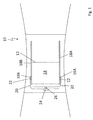
Figure 1 , avehicle roof 10 is shown which is part of a passenger car not being illustrated otherwise, and which includes aroof opening 12, which may selectively be closed or at the very least partially be cleared with the aid of alid element 14. Thelid element 14 thus constitutes a vehicle element, which is movable as against the vehicle structure and is part of a roof opening system. - In order to be able to displace the
lid element 14, the roof opening system includes displacing kinematics, which, in relation to a vertical longitudinal centre plane of the roof on each of their two sides, include adrive slide respective guide rail - For driving, a
drive cable 20 that is rigid in compression and tension is connected to eachdrive slide respective coupling element 22, which is formed from a plastics injection moulded section of therespective drive cable 20 and is connected to therespective drive slide - The
drive cables 20 are guided to acommon drive motor 24 via corresponding guide channels and engage with a commontoothed driving wheel 26 of thedrive motor 24. - The
drive motor 24, thetoothed driving wheel 26 and thedrive cables 20, which are connected to the drive slides 16A and 16B via thecoupling elements 22, hence form a drive unit for thelid member 14. - The
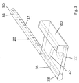
drive cables 20, which are illustrated in a detailed fashion usingFigures 2 to 5 , and are guided in arespective guide channel 28 of therelevant guide rail cylindrical cable body 30 which is made of a bendable plastics material, and which, at the periphery, is provided with adenticulation 32, which extends in the axial direction of thedrive cable 20 and is realised for engaging thetoothed driving wheel 26 that forms a mating denticulation. The denticulation of thedrive cable 20 assigned to driveslide 16A, is arranged on the side of thecable body 30 facing away from theroof opening 12, whereas thedenticulation 32 of thedrive cable 20 assigned to driveslide 16B is arranged on the side of thecable body 30 facing theroof opening 12. - Each of the
drive cables 20 is moreover provided with anarmouring 34, which is formed from a steel wire strand in the present case and reaches through thecable body 30 in the axial direction. Alternatively, thearmouring 34 may also be made from another axially stiff and bendable material. - In a
cable end portion 36, each of thedrive cables 20 is provided with thecoupling element 22 for being connected to therespective drive slide coupling element 22, which adjoins thecable body 32 with a joiningportion 38. The joiningportion 38 has a peripheral face or mantle, which is flush with the peripheral face of thecable body 30, such that thecoupling element 22 may be guided in theguide channel 28 of therelevant guide rail cable body 30. A connectingportion 40 in the manner of a tab projects from the joiningportion 38 in the direction of the respective drive slides 16A or 16B. The connectingportion 40, as it can in particular be learned fromFigure 5 , has an at least nearly L-shaped cross-section for connecting to the respective drive slide. - In order to guarantee that the
coupling element 22 is a racking-resistant part of thedrive cable 20, thearmouring 34, which is guided out of thecable body 30 into thecoupling element 22, forms aninternal anchor element 42, which is formed from an end portion of thearmouring 34 having been bent several times and initially extends, starting from thecable body 30, in the joiningportion 38 and then through the connectingportion 40 close to the face side of thecoupling element 22. In this way, a large joining and anchoring face can be made available by thearmouring 34, and hence a large anchor force for thecoupling element 22. Thecoupling element 22, which adjoins thecable body 30 and has been moulded thereon according to an injection moulding method, thus reaches around thearmouring 34 in a direct manner, wherein theanchor element 42 formed by thearmouring 34, when projected in the longitudinal direction of the cable, is outside of the cross-section of thecable body 30 and is embedded into thecoupling element 22. - In
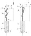
Figure 6 , an alternative embodiment of adrive cable 20 is illustrated, serving to drive a sliding roof lid of the type that is illustrated inFigure 1 and comprising acable body 30, in correspondence with the embodiment according toFigures 2 to 5 , which is provided with a denticulation and through which anarmouring 34 reaches in the axial direction. In acable end portion 36, thearmouring 34 leaves thecable body 30, that means thecable body 30 is removed in thecable end portion 36. In thecable end portion 36, acoupling element 22 is moulded onto thearmouring 34 in a direct manner, said coupling element being realised as a plastics injection moulded section and including a joiningportion 38, which reaches around thearmouring 34 and whose periphery/mantle is flush with the periphery of thecable body 30. A connectingportion 40 being illustrated in dashed lines in the drawing projects, in relation to the axis of thecable 20 in the transverse direction or radial direction, from the joiningportion 38, which adjoins thecable body 30, thedrive cable 20 being able to be joined to a drive slide of the roof opening mechanism via said connectingportion 40. With the embodiment in accordance withFigure 6 , the armouring 34 forms the anchoring for thecoupling element 22. - In
Figure 7 , another embodiment of adrive cable 20 is illustrated, which largely corresponds to the embodiment according toFigure 6 , but differs from the same in that it includes twoarmourings 34 each of which constitutes an armouring harness, and which are freed from acable body 30 in a cable end region 3, but around which acoupling element 22 with the joiningportion 38 thereof reaches. Apart from that, thedrive cable 20 in accordance withFigure 7 corresponds to the drive cable according toFigure 6 . - In
Figures 8 to 14 ,drive cables 20 are in each instance illustrated, formed from acable body 30, in correspondence with the aforedescribed embodiments, said cable body being provided, over at least part of its periphery, with a denticulation extending in the longitudinal direction of the cable for engaging a toothed driving wheel of a drive motor. Anarmouring 34 which is realised as a wire strand, and which extends in the axial direction of thecable body 30, reaches through thecable body 30. In a respectivecable end portion 36, thearmouring 34 is in each instance freed from thecable body 30 so that it is possible that it is provided with acoupling element 22 for being joined to a drive slide of a roof opening mechanism. Thearmouring 34 is deformed in the respectivecable end portion 36 for forming ananchor element 42 for thecoupling element 22 that is realised as a plastics injection moulded section. Therespective anchor element 42 provides mechanical anchoring of thecoupling element 22. - In the embodiment according to
Figure 8 , thearmouring 34 is kinked four times for forming theanchor element 42. - In the embodiment illustrated in
Figure 9 , thearmouring 34, in thecable end portion 36, forms ananchor element 42 in the form of a loop. - In the embodiment in accordance with
Figure 10 , thearmouring 34, in thecable end portion 36, forms ananchor element 42 in the form of a loop, wherein the end of thearmouring 34 once more is folded around an axially running portion of thearmouring 34. - In the embodiment in accordance with
Figure 11 , thearmouring 34, in thecable end portion 36, forms a knot as theanchor element 42 for thecoupling element 22. - In the embodiment in accordance with
Figure 12 , the individual filaments of the wire-like armouring 34 are detached from one another at their ends, such that thearmouring 34 is in a fanned-out state for realising ananchor element 42. - In the embodiment in accordance with
Figure 13 , thearmouring 34 that consists of a wire strand, in thecable end portion 36, is in a widened state in a region spaced apart from the armouring end, such that ananchor element 42 is formed. - In the embodiment in accordance with
Figure 14 , the wire-like armouring 34, in thecable end portion 36, for realising ananchor element 42 in correspondence with the embodiment according toFigure 13 , is likewise in a widened state, in the region spaced apart from the armouring end, wherein the individual filaments of the wire are braided or knotted with one another. - In
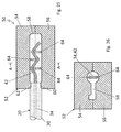
Figures 15 and 16 , another embodiment of adrive cable 20 having acable body 30 which is made of a bendable plastics is illustrated, anarmouring 34 reaching through said cable body in the axial direction. In acable end portion 36, thearmouring 34 is freed from thecable body 30 and is provided with ananchor element 42 realised as a crimp sleeve. Thecrimp sleeve 42 has been slid onto thearmouring 34 and has been crimped there for the purpose of fixation. Acoupling element 22 realised as an injection moulded section encompasses thearmouring 34 and theanchor element 42, thedrive cable 20, in accordance with the above-described embodiments, being able to be connected to a drive slide of roof opening kinematics via saidcoupling element 22. If the at least one armouring has an excentric position with regard to the cable axis, the crimp sleeve may be provided with an excentric hole for inserting the armouring. - In
Figures 17 and 18 , adrive cable 20 is illustrated largely corresponding to the drive cable according toFigures 15 and 16 , but differing from the same in that a sheet metal tab, which forms ananchor element 42, has been crimped in thecable end portion 36 instead of a crimp sleeve. The sheet metal tab extends in the transverse direction of the cable and is completely embedded into thecoupling element 22 realised as a plastics injection moulded section. - In
Figure 19 , adrive cable 20 is illustrated including, in correspondence with the above-described embodiments, acable body 30, through which anarmouring 34 reaches. In acable end portion 36, thearmouring 34, in the region spaced apart from the cable end, is freed from thecable body 30 in an anchoring portion. At the cable end, a portion of thecable body 30 acting as an annular collar thus remains, which serves as ananchor element 42 for acoupling element 22 for connecting thedrive cable 20 to a drive slide of a roof opening mechanism. Thecoupling element 22 directly has been moulded onto thearmouring 34 between theanchor element 42 and thecable body 30. - In
Figure 20 , adrive cable 20 formed from acable body 30 is illustrated, through which cable body anarmouring 34 which is made of a steel wire strand reaches in the axial direction. In acable end portion 36, thecable body 30 has been worked at its periphery, to be precise in such a manner that the peripheral face is realised like ribs for realising ananchor face 44. Acoupling element 22, which constitutes a plastics injection moulded section, is in turn anchored at theanchor face 44. - In
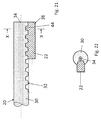
Figures 21 and 22 , another embodiment of adrive cable 20 including acable body 30 is illustrated, which cable body is provided with adenticulation 32 at its periphery. In the axial direction, anarmouring 34 reaches through thecable body 30. In acable end portion 36, in the region of thedenticulation 32, acoupling element 22 is moulded, which constitutes a plastics injection moulded section and serves to connect thedrive cable 20 to a drive slide of a sliding roof mechanism. Thedenticulation 32 forms ananchor face 44 for thecoupling element 22 in thecable end portion 36. - In
Figure 23 , another embodiment of adrive cable 20 being a combination of the embodiments illustrated inFigures 14 and15 is illustrated. Said drive cable thus comprises, in acable end portion 36, for realisinganchor elements 42, a widened dissolved armouring portion on the one hand as well as a crimp sleeve, on the other hand, which has been crimped onto the end of thearmouring 34. - In
Figure 24 , adrive cable 20 being a combination of the embodiments in accordance withFigures 14 and19 is illustrated. For realisinganchor elements 42 for acoupling element 22 realised as an injection moulded section, a widened and dissolved armouring portion of the strand-like armouring and a face-side annular collar which is made of thecable body 30 are therefore disposed in thecable end portion 36. - In
Figures 25 and 26 , a tool for moulding a coupling element onto adrive cable 20 of the kind illustrated inFigure 8 according to an injection moulding process is shown. Thetool 50 comprises atool mould 52 having anupper tool 54 and alower tool 56, and limiting amould cavity 58 for moulding the coupling element. Thetool mould 52, in the closed position illustrated in the drawing, has anopening 60, via which thedrive cable 20 may engage themould cavity 58. Thedrive cable 20, which may be provided with thecoupling element 22 with the aid of thetool 50, has, as already described above, acable body 30 having a cylindrical shape in general and a denticulation, anarmouring 34 reaching through said cable body in the axial direction. In acable end portion 36, the armouring is freed from thecable body 30, i.e. in thecable end portion 36, thecable body 30 is removed from thearmouring 34 before thecable 20 is inserted into thetool mould 52. Thetool mould 52, in the region of theopening 60, is provided with anannular collar 62, such that theopening 60 has an inside diameter which is smaller than the outside diameter of thecable body 30, so that thetool mould 52 presses into the polymer of the cable body during its closing. Thereby, the elasticity of the polymer of thecable body 30, in the closed position of thetool mould 52, may be employed for sealing themould cavity 58, wherein the cylindrical shape of thecable body 30 improves the sealing properties. - In the
mould cavity 58, three pins or lands 64 are arranged, which constitute a deforming installation for thearmouring 34 and with the aid of which, when thetool mould 52 is being closed, the armouringportion 34 freed from thecable body 30 may be deformed for realising ananchor element 42. Two of the pins or lands 64 engage themould cavity 58 from below and one of the pins or lands 64 engages themould cavity 58 from the top, between the two other pins or lands 64. By way of the deforming installation formed by the pins or lands 64, ananchor element 42 for thecoupling element 22 at thedrive cable 20 can thus directly be realised in the mould for producing thecoupling element 22. - In
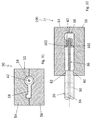
Figures 27 and 28 , atool 70 including atool mould 52 is illustrated, and formed from anupper tool 54 and from alower tool 56, which together limit amould cavity 58 for moulding a coupling element of adrive cable 20 of the kind illustrated inFigure 15 . As already described above, thedrive cable 20 has a substantiallycylindrical cable body 30 having adenticulation 32 and anarmouring 34, which reaches through thecable body 30 in the axial direction and leaves thecable body 30 in acable end portion 36. At the free end of thearmouring 34, a crimp sleeve is fixed, which serves as ananchor element 42 for a coupling element that can be moulded thereon with the aid of thetool 70. In order to be able to exactly position thedrive cable 20 regarding the orientation of thecoupling element 22 to be injected as against the denticulation, thelower tool 56 includes amating denticulation 72, which may be brought into engagement with thedenticulation 32 of thedrive cable 20. - Moreover, the
mould cavity 58, on the side of thecable body 30, is limited by anannular collar 62, whose inside diameter limits anopening 60, via which thedrive cable 20 engages themould cavity 58. In the closed position of thetool mould 52, theannular collar 62 engages thecable body 30 without using further sealing elements, wherein the plastics of thecable body 30 is used for sealing themould cavity 58. - In
Figure 29 , another embodiment of atool 80 for moulding a coupling element onto adrive cable 20 is illustrated. Thetool 80 largely corresponds to the tool according toFigures 27 and 28 , but differs from the same in that it is provided with aslider 82, with the aid of which thedrive cable 20 can be introduced into themould cavity 58 and be removed from themould cavity 58 after thecoupling element 22 has been moulded. Amating denticulation 72 is realised at theslider 82, which denticulation may be brought into engagement with thedenticulation 32 of thedrive cable 20, such that thedrive cable 20 has an exact position as against themould cavity 58 in respect of itsdenticulation 32. Hence, it can be guaranteed that thecoupling element 22 to be moulded likewise has a defined position as against thedenticulation 32 of thedrive cable 20. - In
Figures 30 and31 , atool 90 is illustrated, which likewise serves to mould a coupling element realised as an injection moulded section onto adrive cable 20. Thedrive cable 20 has acable body 30 having anarmouring 34, which leaves thecable body 30 in acable end portion 36 and is provided with ananchor element 42 for thecoupling element 22, said anchor element being realised as a crimp sleeve. On the side facing away from aninlet opening 60 for thedrive cable 20, amould cavity 58 of thetool 90 has a holdingopening 92, at which an end portion of thearmouring 34 can be jammed. Hence, thecable end portion 36 or thearmouring 34 may be kept tensioned in themould cavity 58. After thecoupling element 22 has been moulded onto thedrive cable 20, the excess length of thearmouring 34, which leaves thecoupling element 22 on the side facing away from thecable body 30, can be cut to length. - In
Figure 32 , another embodiment of atool 100 for joining a coupling element is illustrated, serving to connect adrive cable 20 to a drive slide of a sliding roof mechanism. In correspondence with the embodiment according toFigures 30 and31 , thedrive cable 20 has acable end portion 36, which abuts on acable body 30 in the axial direction and in which anarmouring 34, which leaves thecable body 30, is provided with ananchor element 42 realised as a crimp sleeve. In order to keep the armouring portion that is provided with thecrimp sleeve 42, and freed from thecable body 30 tensioned in amould cavity 58 of the moulding tool, anupper tool 54 and alower tool 56 each include a holdingrib 102. Between the holdingribs 102, thearmouring 34 may be jammed in themould cavity 58, such that thecoupling element 22 may directly be injection moulded around thearmouring 34 including theanchor element 42. Apart from that,tool 100 corresponds to the moulding tool illustrated inFigures 30 and31 . - In
Figures 33 and 34 , atool 110 is illustrated, which largely corresponds to the tool according toFigure 32 , but differs from the same in that it does not include any holding ribs for thearmouring 34 of thedrive cable 20. Thetool 110 has anopening 60, too, which, because of anannular collar 62 being present, has an inside diameter that is smaller than the outside diameter of acable body 30 of thedrive cable 20. Thecable body 20 or the plastics thereof may therefore be used for sealing themould cavity 58. - In
Figures 35 and 36 , atool 120 for moulding a coupling element onto adrive cable 20 of the kind illustrated inFigure 18 is shown. Themould cavity 58 of thetool 120 has, asFigure 36 shows a cross-section oftool 120 along section E-E ofFigure 35 , having an S-shapedcavity 58. In thecavity 58, an anchor tab of twice bent sheet metal is crimped onto thearmouring 34 of the drive cable thereby forming ananchor element 42 for thecoupling element 22 at thedrive cable 20. -
- 10
- vehicle roof
- 12
- roof opening
- 14
- lid element
- 16A, B
- drive slide
- 18A, B
- guide rails
- 20
- drive cable
- 22
- coupling element
- 24
- drive motor
- 26
- driving toothed wheel
- 28
- guide channel
- 30
- cable body
- 32
- denticulation
- 34
- armouring
- 36
- cable end portion
- 38
- joining portion
- 40
- connecting portion
- 42
- anchor element
- 44
- anchor surface
- 50
- tool
- 52
- tool mould
- 54
- upper tool
- 56
- lower tool
- 58
- mould cavity
- 60
- opening
- 62
- annular collar
- 64
- lands/pins
- 70
- tool
- 72
- mating denticulation
- 80
- tool
- 82
- slider
- 90
- tool
- 92
- holding opening
- 100
- tool
- 102
- holding ribs
- 110
- tool
- 120
- tool
Claims (18)
- A drive cable for actuating an element being movable relative to a structure, comprising a cable body (30) which is made of one or more plastics, and which comprises a denticulation (32) extending in the axial direction for engaging a mating denticulation as well as at least one armouring (34), which extends through the cable body (30) in the axial direction, characterised by a coupling element (22) which is realised as a moulded section, and which is moulded in a cable connecting region (36) so as to adjoin the cable body (30) and includes a connecting portion (40) for being coupled to the moveable element.
- The drive cable according to claim 1, characterised in that the coupling element (22) encases the armouring (34) and is directly moulded onto the same.
- The drive cable according to claim 1 or 2, characterised in that the armouring (34) is provided with an anchor element (42) for the coupling element (22).
- The drive cable according to claim 3, characterised in that a deformed armouring portion forms the anchor element (42).
- The drive cable according to claim 4, characterised in that the deformed armouring portion forms an armouring loop.
- The drive cable according to claim 4 or 5, characterised in that the deformed armouring portion, being projected in the longitudinal direction of the cable, is outside of the cable body (30) and is embedded into the coupling element (22).
- The drive cable according to any one of the claims 3 to 6, characterised in that at least one wire comprising filaments forms the armouring (34), which filaments are in a disentangled or widened state for forming the anchor element (42).
- The drive cable according to claim 3, characterised in that the anchor element (42) is a separate piece, which is fixed to the armouring (34).
- The drive cable according to claim 3, characterised in that an end-side portion of the cable body (30) forms the anchor element (42), an armouring portion abutting on said end-side portion in the longitudinal direction of the cable, and the coupling element (22) directly being moulded onto the armouring portion.
- The drive cable according to any one of the claims 1 to 9, characterised in that the coupling element (22) is moulded onto the periphery of the cable body (30).
- The drive cable according to claim 10, characterised in that the cable body (30), at the periphery, includes a structured anchor surface (44) for the coupling element (22).
- The drive cable according to one of claims 1 to 11, characterized in that the connecting portion (40) of the coupling element (22) has a defined position with respect to the denticulation (32).
- A tool for moulding a coupling element (22) being realised as an injection moulded section to a drive cable, which serves to actuate a structural element being movable as against a structure and comprises a cable body (30) which is made of plastics, and which includes a denticulation (32) extending in the axial direction for engaging a mating denticulation as well as at least one armouring (34), which continuously reaches through the cable body (30) in the axial direction, comprising a tool mould (52) having a mould cavity (58), which corresponds to the coupling element (22) and includes an opening (60) having a cross section designed according to the cross section of the cable body (30) and via which the drive cable (20) can be introduced into the mould cavity (58).
- The tool according to claim 13, characterized in that the opening (60) has an inside diameter, which is smaller than the outside diameter of the cable body (30), wherein the tool mould (52) includes a sealing surface in the region of the opening, said sealing surface resting against the cable body (30) when the drive cable (20) engages the mould cavity (58).
- The tool according to claim 13 or 14, characterized in that the opening (60) is a seal-free opening.
- The tool according to one of claims 13 to 15, characterised in that the tool mould (52) has a holding element for the armouring of the drive cable.
- The tool according to one of claims 13 to 16, characterised in that the tool mould (52) includes a deforming arrangement for the armouring (34) of the drive cable (20).
- The tool according to any one of the claims 13 to 17, characterised in that the tool mould (54) includes a positioning means for defining the orientation of the cable in the tool mould (54), which is preferably realized by a denticulation, which engages the denticulation (32) of the cable body (30) when the drive cable (20) engages the mould cavity (58).
Priority Applications (5)
| Application Number | Priority Date | Filing Date | Title |
|---|---|---|---|
| PL16158982T PL3216637T3 (en) | 2016-03-07 | 2016-03-07 | Drive cable having a plastics cable body |
| EP16158982.5A EP3216637B1 (en) | 2016-03-07 | 2016-03-07 | Drive cable having a plastics cable body |
| PCT/EP2017/052589 WO2017153103A1 (en) | 2016-03-07 | 2017-02-07 | Drive cable having a plastics cable body |
| CN201780024669.6A CN109153320B (en) | 2016-03-07 | 2017-02-07 | Drive cable with plastic cable body |
| US16/081,116 US10843541B2 (en) | 2016-03-07 | 2017-02-07 | Drive cable having a plastics cable body |
Applications Claiming Priority (1)
| Application Number | Priority Date | Filing Date | Title |
|---|---|---|---|
| EP16158982.5A EP3216637B1 (en) | 2016-03-07 | 2016-03-07 | Drive cable having a plastics cable body |
Publications (2)
| Publication Number | Publication Date |
|---|---|
| EP3216637A1 true EP3216637A1 (en) | 2017-09-13 |
| EP3216637B1 EP3216637B1 (en) | 2019-11-27 |
Family
ID=55527303
Family Applications (1)
| Application Number | Title | Priority Date | Filing Date |
|---|---|---|---|
| EP16158982.5A Active EP3216637B1 (en) | 2016-03-07 | 2016-03-07 | Drive cable having a plastics cable body |
Country Status (5)
| Country | Link |
|---|---|
| US (1) | US10843541B2 (en) |
| EP (1) | EP3216637B1 (en) |
| CN (1) | CN109153320B (en) |
| PL (1) | PL3216637T3 (en) |
| WO (1) | WO2017153103A1 (en) |
Families Citing this family (4)
| Publication number | Priority date | Publication date | Assignee | Title |
|---|---|---|---|---|
| DE102017122496A1 (en) * | 2017-09-27 | 2019-03-28 | Webasto SE | Roller blind system for a vehicle roof |
| DE102018221080A1 (en) | 2018-12-06 | 2020-06-10 | Bos Gmbh & Co. Kg | Drive device for a movable roof part of a roof system and threaded cable for such a drive device |
| JP7096281B2 (en) * | 2020-03-30 | 2022-07-05 | 本田技研工業株式会社 | Transmission member structure, accelerator cable structure, method of manufacturing transmission member |
| US12297008B2 (en) * | 2021-07-18 | 2025-05-13 | Jeanne Sutton | Modular rail-based storage system |
Citations (5)
| Publication number | Priority date | Publication date | Assignee | Title |
|---|---|---|---|---|
| FR1011827A (en) * | 1949-03-30 | 1952-06-27 | Method of manufacturing stop heads for brake cables for bicycles and other vehicles | |
| DE2912666A1 (en) * | 1978-03-30 | 1979-10-04 | Aisin Seiki | Connector for vehicle sliding roof cable - has integrally embedded cable in side projection sliding inside groove |
| GB1595251A (en) * | 1977-01-21 | 1981-08-12 | American Chain & Cable Co | Conduits |
| WO2007128290A1 (en) * | 2006-05-08 | 2007-11-15 | Webasto Ag | Vehicle roof with a roof part which can be moved by means of a drive cable |
| DE102012105372A1 (en) * | 2012-06-20 | 2013-12-24 | Webasto Ag | Drive system for vehicle chassis cover element mounted in vehicle roof of passenger car, has reinforcing band that extends to neutral axis of drive cables, such that height of tooth of cables is less than half the diameter of cables |
Family Cites Families (10)
| Publication number | Priority date | Publication date | Assignee | Title |
|---|---|---|---|---|
| US3206998A (en) * | 1963-04-08 | 1965-09-21 | Teleflex Inc | Remote control apparatus |
| US3766801A (en) * | 1971-10-27 | 1973-10-23 | Teleflex Inc | Actuator assembly |
| GB1397336A (en) * | 1972-05-11 | 1975-06-11 | Teleflex Ltd | Steering systems |
| IT1245511B (en) * | 1991-02-15 | 1994-09-29 | Gate Spa | TOOTHED FLEXIBLE TRANSMISSION CABLE, PROCEDURE FOR ITS MANUFACTURE AND TRANSMISSION MECHANISM INCLUDING SUCH CABLE |
| US5337621A (en) * | 1993-11-18 | 1994-08-16 | Teleflex Incorporated | Cable end fitting retainer and method for making same |
| DE19727738C1 (en) * | 1997-06-30 | 1998-10-01 | Rockwell International Gmbh | Operating device for cover of motor vehicle sliding roof |
| EP2329978B1 (en) * | 2009-12-01 | 2013-02-13 | Roof Systems Germany GmbH | Assembly including a sun-roof and a sun-screen |
| US8961061B2 (en) * | 2010-08-07 | 2015-02-24 | Gulf Copper | Cable connection systems and methods |
| DE102014106950A1 (en) * | 2014-05-16 | 2015-11-19 | Webasto SE | Roller blind arrangement with side guide |
| DE102015115285A1 (en) * | 2015-09-10 | 2017-03-16 | Webasto SE | Arrangement for a movable roof element for a motor vehicle and system for a motor vehicle |
-
2016
- 2016-03-07 EP EP16158982.5A patent/EP3216637B1/en active Active
- 2016-03-07 PL PL16158982T patent/PL3216637T3/en unknown
-
2017
- 2017-02-07 CN CN201780024669.6A patent/CN109153320B/en not_active Expired - Fee Related
- 2017-02-07 WO PCT/EP2017/052589 patent/WO2017153103A1/en not_active Ceased
- 2017-02-07 US US16/081,116 patent/US10843541B2/en active Active
Patent Citations (5)
| Publication number | Priority date | Publication date | Assignee | Title |
|---|---|---|---|---|
| FR1011827A (en) * | 1949-03-30 | 1952-06-27 | Method of manufacturing stop heads for brake cables for bicycles and other vehicles | |
| GB1595251A (en) * | 1977-01-21 | 1981-08-12 | American Chain & Cable Co | Conduits |
| DE2912666A1 (en) * | 1978-03-30 | 1979-10-04 | Aisin Seiki | Connector for vehicle sliding roof cable - has integrally embedded cable in side projection sliding inside groove |
| WO2007128290A1 (en) * | 2006-05-08 | 2007-11-15 | Webasto Ag | Vehicle roof with a roof part which can be moved by means of a drive cable |
| DE102012105372A1 (en) * | 2012-06-20 | 2013-12-24 | Webasto Ag | Drive system for vehicle chassis cover element mounted in vehicle roof of passenger car, has reinforcing band that extends to neutral axis of drive cables, such that height of tooth of cables is less than half the diameter of cables |
Also Published As
| Publication number | Publication date |
|---|---|
| PL3216637T3 (en) | 2020-06-29 |
| WO2017153103A1 (en) | 2017-09-14 |
| CN109153320B (en) | 2022-03-11 |
| US10843541B2 (en) | 2020-11-24 |
| CN109153320A (en) | 2019-01-04 |
| US20190084389A1 (en) | 2019-03-21 |
| EP3216637B1 (en) | 2019-11-27 |
Similar Documents
| Publication | Publication Date | Title |
|---|---|---|
| US10843541B2 (en) | Drive cable having a plastics cable body | |
| US6034329A (en) | Corrugated tube and an automatic wire-loading device therefor | |
| US3987144A (en) | Method for the removal of a mold core from an injection molded plastic duct section | |
| US20230208261A1 (en) | Apparatus and method for manufacturing a stator | |
| DE10222654B4 (en) | joint | |
| US6352602B1 (en) | Bead wire winding device and winding method | |
| EP2168800A1 (en) | A corner portion for a hidden frame window run, a sealing gasket forming this run and a sealing system incorporating it | |
| US11136803B2 (en) | Window regulator and method of assembling the same | |
| JP2003264964A (en) | Method for forming a segment for a coil of a rotating electrical machine and a forming die structure used therefor | |
| CN100475075C (en) | Pullers for zippers with automatic brakes | |
| KR102938890B1 (en) | staple | |
| CN106286508A (en) | Clamp device | |
| US20100253175A1 (en) | Isolator ring for an electric motor | |
| US11136809B2 (en) | Window regulator and method of assembling the same | |
| JP2002519974A (en) | A device comprising a plurality of securing members for holding a tightened cable bundle surrounded by a cable band | |
| US11203256B2 (en) | Vehicle roof comprising a mobile roof element | |
| CN106364448A (en) | Buckle device | |
| JP2520173Y2 (en) | Unity band group | |
| JP5633967B2 (en) | Coil insertion method and coil insertion device | |
| SK283130B6 (en) | Chain of closure clips and device and process for closing its clips | |
| CN101925756B (en) | Closing cap for driving cable, driving cable, method for producing closing cap and method for producing driving cable | |
| GB2328708A (en) | Attaching material to a seat | |
| CN107054872A (en) | Band | |
| EP3419820B1 (en) | Method for producing a sealing element | |
| WO2016005078A1 (en) | Method for producing a complete insulation |
Legal Events
| Date | Code | Title | Description |
|---|---|---|---|
| PUAI | Public reference made under article 153(3) epc to a published international application that has entered the european phase |
Free format text: ORIGINAL CODE: 0009012 |
|
| STAA | Information on the status of an ep patent application or granted ep patent |
Free format text: STATUS: THE APPLICATION HAS BEEN PUBLISHED |
|
| AK | Designated contracting states |
Kind code of ref document: A1 Designated state(s): AL AT BE BG CH CY CZ DE DK EE ES FI FR GB GR HR HU IE IS IT LI LT LU LV MC MK MT NL NO PL PT RO RS SE SI SK SM TR |
|
| AX | Request for extension of the european patent |
Extension state: BA ME |
|
| STAA | Information on the status of an ep patent application or granted ep patent |
Free format text: STATUS: REQUEST FOR EXAMINATION WAS MADE |
|
| 17P | Request for examination filed |
Effective date: 20180222 |
|
| RBV | Designated contracting states (corrected) |
Designated state(s): AL AT BE BG CH CY CZ DE DK EE ES FI FR GB GR HR HU IE IS IT LI LT LU LV MC MK MT NL NO PL PT RO RS SE SI SK SM TR |
|
| STAA | Information on the status of an ep patent application or granted ep patent |
Free format text: STATUS: EXAMINATION IS IN PROGRESS |
|
| 17Q | First examination report despatched |
Effective date: 20181012 |
|
| GRAP | Despatch of communication of intention to grant a patent |
Free format text: ORIGINAL CODE: EPIDOSNIGR1 |
|
| STAA | Information on the status of an ep patent application or granted ep patent |
Free format text: STATUS: GRANT OF PATENT IS INTENDED |
|
| INTG | Intention to grant announced |
Effective date: 20190603 |
|
| GRAS | Grant fee paid |
Free format text: ORIGINAL CODE: EPIDOSNIGR3 |
|
| GRAA | (expected) grant |
Free format text: ORIGINAL CODE: 0009210 |
|
| STAA | Information on the status of an ep patent application or granted ep patent |
Free format text: STATUS: THE PATENT HAS BEEN GRANTED |
|
| AK | Designated contracting states |
Kind code of ref document: B1 Designated state(s): AL AT BE BG CH CY CZ DE DK EE ES FI FR GB GR HR HU IE IS IT LI LT LU LV MC MK MT NL NO PL PT RO RS SE SI SK SM TR |
|
| REG | Reference to a national code |
Ref country code: GB Ref legal event code: FG4D |
|
| REG | Reference to a national code |
Ref country code: CH Ref legal event code: EP |
|
| REG | Reference to a national code |
Ref country code: AT Ref legal event code: REF Ref document number: 1206253 Country of ref document: AT Kind code of ref document: T Effective date: 20191215 |
|
| REG | Reference to a national code |
Ref country code: DE Ref legal event code: R096 Ref document number: 602016024917 Country of ref document: DE |
|
| REG | Reference to a national code |
Ref country code: IE Ref legal event code: FG4D |
|
| REG | Reference to a national code |
Ref country code: NL Ref legal event code: MP Effective date: 20191127 |
|
| REG | Reference to a national code |
Ref country code: LT Ref legal event code: MG4D |
|
| PG25 | Lapsed in a contracting state [announced via postgrant information from national office to epo] |
Ref country code: NL Free format text: LAPSE BECAUSE OF FAILURE TO SUBMIT A TRANSLATION OF THE DESCRIPTION OR TO PAY THE FEE WITHIN THE PRESCRIBED TIME-LIMIT Effective date: 20191127 Ref country code: LT Free format text: LAPSE BECAUSE OF FAILURE TO SUBMIT A TRANSLATION OF THE DESCRIPTION OR TO PAY THE FEE WITHIN THE PRESCRIBED TIME-LIMIT Effective date: 20191127 Ref country code: GR Free format text: LAPSE BECAUSE OF FAILURE TO SUBMIT A TRANSLATION OF THE DESCRIPTION OR TO PAY THE FEE WITHIN THE PRESCRIBED TIME-LIMIT Effective date: 20200228 Ref country code: NO Free format text: LAPSE BECAUSE OF FAILURE TO SUBMIT A TRANSLATION OF THE DESCRIPTION OR TO PAY THE FEE WITHIN THE PRESCRIBED TIME-LIMIT Effective date: 20200227 Ref country code: LV Free format text: LAPSE BECAUSE OF FAILURE TO SUBMIT A TRANSLATION OF THE DESCRIPTION OR TO PAY THE FEE WITHIN THE PRESCRIBED TIME-LIMIT Effective date: 20191127 Ref country code: SE Free format text: LAPSE BECAUSE OF FAILURE TO SUBMIT A TRANSLATION OF THE DESCRIPTION OR TO PAY THE FEE WITHIN THE PRESCRIBED TIME-LIMIT Effective date: 20191127 Ref country code: FI Free format text: LAPSE BECAUSE OF FAILURE TO SUBMIT A TRANSLATION OF THE DESCRIPTION OR TO PAY THE FEE WITHIN THE PRESCRIBED TIME-LIMIT Effective date: 20191127 Ref country code: BG Free format text: LAPSE BECAUSE OF FAILURE TO SUBMIT A TRANSLATION OF THE DESCRIPTION OR TO PAY THE FEE WITHIN THE PRESCRIBED TIME-LIMIT Effective date: 20200227 |
|
| REG | Reference to a national code |
Ref country code: SK Ref legal event code: T3 Ref document number: E 33469 Country of ref document: SK |
|
| PG25 | Lapsed in a contracting state [announced via postgrant information from national office to epo] |
Ref country code: RS Free format text: LAPSE BECAUSE OF FAILURE TO SUBMIT A TRANSLATION OF THE DESCRIPTION OR TO PAY THE FEE WITHIN THE PRESCRIBED TIME-LIMIT Effective date: 20191127 Ref country code: IS Free format text: LAPSE BECAUSE OF FAILURE TO SUBMIT A TRANSLATION OF THE DESCRIPTION OR TO PAY THE FEE WITHIN THE PRESCRIBED TIME-LIMIT Effective date: 20200327 Ref country code: HR Free format text: LAPSE BECAUSE OF FAILURE TO SUBMIT A TRANSLATION OF THE DESCRIPTION OR TO PAY THE FEE WITHIN THE PRESCRIBED TIME-LIMIT Effective date: 20191127 |
|
| PG25 | Lapsed in a contracting state [announced via postgrant information from national office to epo] |
Ref country code: AL Free format text: LAPSE BECAUSE OF FAILURE TO SUBMIT A TRANSLATION OF THE DESCRIPTION OR TO PAY THE FEE WITHIN THE PRESCRIBED TIME-LIMIT Effective date: 20191127 |
|
| PG25 | Lapsed in a contracting state [announced via postgrant information from national office to epo] |
Ref country code: PT Free format text: LAPSE BECAUSE OF FAILURE TO SUBMIT A TRANSLATION OF THE DESCRIPTION OR TO PAY THE FEE WITHIN THE PRESCRIBED TIME-LIMIT Effective date: 20200419 Ref country code: EE Free format text: LAPSE BECAUSE OF FAILURE TO SUBMIT A TRANSLATION OF THE DESCRIPTION OR TO PAY THE FEE WITHIN THE PRESCRIBED TIME-LIMIT Effective date: 20191127 Ref country code: DK Free format text: LAPSE BECAUSE OF FAILURE TO SUBMIT A TRANSLATION OF THE DESCRIPTION OR TO PAY THE FEE WITHIN THE PRESCRIBED TIME-LIMIT Effective date: 20191127 Ref country code: ES Free format text: LAPSE BECAUSE OF FAILURE TO SUBMIT A TRANSLATION OF THE DESCRIPTION OR TO PAY THE FEE WITHIN THE PRESCRIBED TIME-LIMIT Effective date: 20191127 Ref country code: RO Free format text: LAPSE BECAUSE OF FAILURE TO SUBMIT A TRANSLATION OF THE DESCRIPTION OR TO PAY THE FEE WITHIN THE PRESCRIBED TIME-LIMIT Effective date: 20191127 |
|
| REG | Reference to a national code |
Ref country code: DE Ref legal event code: R097 Ref document number: 602016024917 Country of ref document: DE |
|
| PG25 | Lapsed in a contracting state [announced via postgrant information from national office to epo] |
Ref country code: SM Free format text: LAPSE BECAUSE OF FAILURE TO SUBMIT A TRANSLATION OF THE DESCRIPTION OR TO PAY THE FEE WITHIN THE PRESCRIBED TIME-LIMIT Effective date: 20191127 |
|
| REG | Reference to a national code |
Ref country code: AT Ref legal event code: MK05 Ref document number: 1206253 Country of ref document: AT Kind code of ref document: T Effective date: 20191127 |
|
| PLBE | No opposition filed within time limit |
Free format text: ORIGINAL CODE: 0009261 |
|
| STAA | Information on the status of an ep patent application or granted ep patent |
Free format text: STATUS: NO OPPOSITION FILED WITHIN TIME LIMIT |
|
| PG25 | Lapsed in a contracting state [announced via postgrant information from national office to epo] |
Ref country code: MC Free format text: LAPSE BECAUSE OF FAILURE TO SUBMIT A TRANSLATION OF THE DESCRIPTION OR TO PAY THE FEE WITHIN THE PRESCRIBED TIME-LIMIT Effective date: 20191127 |
|
| REG | Reference to a national code |
Ref country code: CH Ref legal event code: PL |
|
| 26N | No opposition filed |
Effective date: 20200828 |
|
| PG25 | Lapsed in a contracting state [announced via postgrant information from national office to epo] |
Ref country code: SI Free format text: LAPSE BECAUSE OF FAILURE TO SUBMIT A TRANSLATION OF THE DESCRIPTION OR TO PAY THE FEE WITHIN THE PRESCRIBED TIME-LIMIT Effective date: 20191127 Ref country code: AT Free format text: LAPSE BECAUSE OF FAILURE TO SUBMIT A TRANSLATION OF THE DESCRIPTION OR TO PAY THE FEE WITHIN THE PRESCRIBED TIME-LIMIT Effective date: 20191127 |
|
| REG | Reference to a national code |
Ref country code: BE Ref legal event code: MM Effective date: 20200331 |
|
| PG25 | Lapsed in a contracting state [announced via postgrant information from national office to epo] |
Ref country code: LU Free format text: LAPSE BECAUSE OF NON-PAYMENT OF DUE FEES Effective date: 20200307 |
|
| PG25 | Lapsed in a contracting state [announced via postgrant information from national office to epo] |
Ref country code: IE Free format text: LAPSE BECAUSE OF NON-PAYMENT OF DUE FEES Effective date: 20200307 Ref country code: CH Free format text: LAPSE BECAUSE OF NON-PAYMENT OF DUE FEES Effective date: 20200331 Ref country code: LI Free format text: LAPSE BECAUSE OF NON-PAYMENT OF DUE FEES Effective date: 20200331 Ref country code: IT Free format text: LAPSE BECAUSE OF FAILURE TO SUBMIT A TRANSLATION OF THE DESCRIPTION OR TO PAY THE FEE WITHIN THE PRESCRIBED TIME-LIMIT Effective date: 20191127 |
|
| PG25 | Lapsed in a contracting state [announced via postgrant information from national office to epo] |
Ref country code: BE Free format text: LAPSE BECAUSE OF NON-PAYMENT OF DUE FEES Effective date: 20200331 |
|
| PG25 | Lapsed in a contracting state [announced via postgrant information from national office to epo] |
Ref country code: TR Free format text: LAPSE BECAUSE OF FAILURE TO SUBMIT A TRANSLATION OF THE DESCRIPTION OR TO PAY THE FEE WITHIN THE PRESCRIBED TIME-LIMIT Effective date: 20191127 Ref country code: MT Free format text: LAPSE BECAUSE OF FAILURE TO SUBMIT A TRANSLATION OF THE DESCRIPTION OR TO PAY THE FEE WITHIN THE PRESCRIBED TIME-LIMIT Effective date: 20191127 Ref country code: CY Free format text: LAPSE BECAUSE OF FAILURE TO SUBMIT A TRANSLATION OF THE DESCRIPTION OR TO PAY THE FEE WITHIN THE PRESCRIBED TIME-LIMIT Effective date: 20191127 |
|
| PG25 | Lapsed in a contracting state [announced via postgrant information from national office to epo] |
Ref country code: MK Free format text: LAPSE BECAUSE OF FAILURE TO SUBMIT A TRANSLATION OF THE DESCRIPTION OR TO PAY THE FEE WITHIN THE PRESCRIBED TIME-LIMIT Effective date: 20191127 |
|
| PGFP | Annual fee paid to national office [announced via postgrant information from national office to epo] |
Ref country code: DE Payment date: 20240320 Year of fee payment: 9 Ref country code: CZ Payment date: 20240228 Year of fee payment: 9 Ref country code: GB Payment date: 20240320 Year of fee payment: 9 Ref country code: SK Payment date: 20240227 Year of fee payment: 9 |
|
| PGFP | Annual fee paid to national office [announced via postgrant information from national office to epo] |
Ref country code: PL Payment date: 20240226 Year of fee payment: 9 Ref country code: FR Payment date: 20240328 Year of fee payment: 9 |
|
| REG | Reference to a national code |
Ref country code: DE Ref legal event code: R119 Ref document number: 602016024917 Country of ref document: DE |
|
| REG | Reference to a national code |
Ref country code: SK Ref legal event code: MM4A Ref document number: E 33469 Country of ref document: SK Effective date: 20250307 |
|
| PG25 | Lapsed in a contracting state [announced via postgrant information from national office to epo] |
Ref country code: CZ Free format text: LAPSE BECAUSE OF NON-PAYMENT OF DUE FEES Effective date: 20250307 |
|
| GBPC | Gb: european patent ceased through non-payment of renewal fee |
Effective date: 20250307 |
|
| PG25 | Lapsed in a contracting state [announced via postgrant information from national office to epo] |
Ref country code: DE Free format text: LAPSE BECAUSE OF NON-PAYMENT OF DUE FEES Effective date: 20251001 |
|
| PG25 | Lapsed in a contracting state [announced via postgrant information from national office to epo] |
Ref country code: GB Free format text: LAPSE BECAUSE OF NON-PAYMENT OF DUE FEES Effective date: 20250307 |
|
| PG25 | Lapsed in a contracting state [announced via postgrant information from national office to epo] |
Ref country code: FR Free format text: LAPSE BECAUSE OF NON-PAYMENT OF DUE FEES Effective date: 20250331 |
|
| PG25 | Lapsed in a contracting state [announced via postgrant information from national office to epo] |
Ref country code: SK Free format text: LAPSE BECAUSE OF NON-PAYMENT OF DUE FEES Effective date: 20250307 |