EP3216631A1 - Oil-hydraulic suspension for vehicles - Google Patents
Oil-hydraulic suspension for vehicles Download PDFInfo
- Publication number
- EP3216631A1 EP3216631A1 EP17157691.1A EP17157691A EP3216631A1 EP 3216631 A1 EP3216631 A1 EP 3216631A1 EP 17157691 A EP17157691 A EP 17157691A EP 3216631 A1 EP3216631 A1 EP 3216631A1
- Authority
- EP
- European Patent Office
- Prior art keywords
- axle
- oil
- chassis
- suspension
- connecting arm
- Prior art date
- Legal status (The legal status is an assumption and is not a legal conclusion. Google has not performed a legal analysis and makes no representation as to the accuracy of the status listed.)
- Withdrawn
Links
- 239000000725 suspension Substances 0.000 title claims abstract description 88
- 230000009471 action Effects 0.000 claims description 7
- 230000008878 coupling Effects 0.000 description 2
- 238000010168 coupling process Methods 0.000 description 2
- 238000005859 coupling reaction Methods 0.000 description 2
- 238000006243 chemical reaction Methods 0.000 description 1
- 230000001419 dependent effect Effects 0.000 description 1
- 230000000694 effects Effects 0.000 description 1
- 230000007613 environmental effect Effects 0.000 description 1
- 239000012530 fluid Substances 0.000 description 1
- 239000011261 inert gas Substances 0.000 description 1
- 239000000463 material Substances 0.000 description 1
- 230000004048 modification Effects 0.000 description 1
- 238000012986 modification Methods 0.000 description 1
- 230000009467 reduction Effects 0.000 description 1
- 238000007789 sealing Methods 0.000 description 1
Images




Classifications
-
- B—PERFORMING OPERATIONS; TRANSPORTING
- B60—VEHICLES IN GENERAL
- B60G—VEHICLE SUSPENSION ARRANGEMENTS
- B60G9/00—Resilient suspensions of a rigid axle or axle housing for two or more wheels
- B60G9/003—Resilient suspensions of a rigid axle or axle housing for two or more wheels the axle being rigidly connected to a trailing guiding device
-
- B—PERFORMING OPERATIONS; TRANSPORTING
- B60—VEHICLES IN GENERAL
- B60G—VEHICLE SUSPENSION ARRANGEMENTS
- B60G11/00—Resilient suspensions characterised by arrangement, location or kind of springs
- B60G11/26—Resilient suspensions characterised by arrangement, location or kind of springs having fluid springs only, e.g. hydropneumatic springs
- B60G11/265—Resilient suspensions characterised by arrangement, location or kind of springs having fluid springs only, e.g. hydropneumatic springs hydraulic springs
-
- B—PERFORMING OPERATIONS; TRANSPORTING
- B60—VEHICLES IN GENERAL
- B60G—VEHICLE SUSPENSION ARRANGEMENTS
- B60G11/00—Resilient suspensions characterised by arrangement, location or kind of springs
- B60G11/26—Resilient suspensions characterised by arrangement, location or kind of springs having fluid springs only, e.g. hydropneumatic springs
- B60G11/28—Resilient suspensions characterised by arrangement, location or kind of springs having fluid springs only, e.g. hydropneumatic springs characterised by means specially adapted for attaching the spring to axle or sprung part of the vehicle
-
- B—PERFORMING OPERATIONS; TRANSPORTING
- B60—VEHICLES IN GENERAL
- B60G—VEHICLE SUSPENSION ARRANGEMENTS
- B60G2200/00—Indexing codes relating to suspension types
- B60G2200/30—Rigid axle suspensions
- B60G2200/31—Rigid axle suspensions with two trailing arms rigidly connected to the axle
-
- B—PERFORMING OPERATIONS; TRANSPORTING
- B60—VEHICLES IN GENERAL
- B60G—VEHICLE SUSPENSION ARRANGEMENTS
- B60G2202/00—Indexing codes relating to the type of spring, damper or actuator
- B60G2202/10—Type of spring
- B60G2202/15—Fluid spring
- B60G2202/154—Fluid spring with an accumulator
-
- B—PERFORMING OPERATIONS; TRANSPORTING
- B60—VEHICLES IN GENERAL
- B60G—VEHICLE SUSPENSION ARRANGEMENTS
- B60G2204/00—Indexing codes related to suspensions per se or to auxiliary parts
- B60G2204/10—Mounting of suspension elements
- B60G2204/14—Mounting of suspension arms
- B60G2204/148—Mounting of suspension arms on the unsprung part of the vehicle, e.g. wheel knuckle or rigid axle
-
- B—PERFORMING OPERATIONS; TRANSPORTING
- B60—VEHICLES IN GENERAL
- B60G—VEHICLE SUSPENSION ARRANGEMENTS
- B60G2204/00—Indexing codes related to suspensions per se or to auxiliary parts
- B60G2204/40—Auxiliary suspension parts; Adjustment of suspensions
- B60G2204/43—Fittings, brackets or knuckles
- B60G2204/4302—Fittings, brackets or knuckles for fixing suspension arm on the vehicle body or chassis
-
- B—PERFORMING OPERATIONS; TRANSPORTING
- B60—VEHICLES IN GENERAL
- B60G—VEHICLE SUSPENSION ARRANGEMENTS
- B60G2204/00—Indexing codes related to suspensions per se or to auxiliary parts
- B60G2204/40—Auxiliary suspension parts; Adjustment of suspensions
- B60G2204/43—Fittings, brackets or knuckles
- B60G2204/4306—Bracket or knuckle for rigid axles, e.g. for clamping
-
- B—PERFORMING OPERATIONS; TRANSPORTING
- B60—VEHICLES IN GENERAL
- B60G—VEHICLE SUSPENSION ARRANGEMENTS
- B60G2206/00—Indexing codes related to the manufacturing of suspensions: constructional features, the materials used, procedures or tools
- B60G2206/01—Constructional features of suspension elements, e.g. arms, dampers, springs
- B60G2206/012—Hollow or tubular elements
-
- B—PERFORMING OPERATIONS; TRANSPORTING
- B60—VEHICLES IN GENERAL
- B60G—VEHICLE SUSPENSION ARRANGEMENTS
- B60G2206/00—Indexing codes related to the manufacturing of suspensions: constructional features, the materials used, procedures or tools
- B60G2206/01—Constructional features of suspension elements, e.g. arms, dampers, springs
- B60G2206/60—Subframe construction
- B60G2206/601—Hanger bracket
-
- B—PERFORMING OPERATIONS; TRANSPORTING
- B60—VEHICLES IN GENERAL
- B60G—VEHICLE SUSPENSION ARRANGEMENTS
- B60G2300/00—Indexing codes relating to the type of vehicle
- B60G2300/04—Trailers
-
- B—PERFORMING OPERATIONS; TRANSPORTING
- B60—VEHICLES IN GENERAL
- B60G—VEHICLE SUSPENSION ARRANGEMENTS
- B60G2300/00—Indexing codes relating to the type of vehicle
- B60G2300/08—Agricultural vehicles
-
- B—PERFORMING OPERATIONS; TRANSPORTING
- B60—VEHICLES IN GENERAL
- B60G—VEHICLE SUSPENSION ARRANGEMENTS
- B60G2300/00—Indexing codes relating to the type of vehicle
- B60G2300/08—Agricultural vehicles
- B60G2300/082—Tractors
Definitions
- the present invention refers to an oil-hydraulic suspension for connecting a chassis to an axle of a vehicle.
- a traditional oil-hydraulic suspension generally comprises a main load-bearing body that is coupleable to the chassis of the vehicle, an oil-hydraulic suspension cylinder hinged to the chassis of the vehicle, a connecting arm for connecting the axle to the main load-bearing body hinged to the main body, and specific fastening members for fastening the arm to the axle.
- Oil-hydraulic suspensions are among those most widely used on tractor-drawn farm machinery, in place of the traditional mechanical leaf spring suspensions.
- An oil-hydraulic suspension enables homogeneous distribution of the weight of the vehicle on the wheels and therefore optimal traction even in the presence of dynamic loads because the hydraulic circuit keeps all actuators at the same pressure.
- oil- hydraulic suspension also makes it possible to adjust the ground clearance of the vehicle by intervening on the volume of fluid in the actuators.
- an oil-hydraulic suspension optimizes the drive behaviour/ride comfort by coupling one or more elastic elements, for example inert gas accumulators, to the rigid oil-hydraulic circuit.
- supply through the hydraulic system is standard for all tractors.
- the low attachment of the cylinder requires its passage alongside the arm and in the second case it is because the high attachment of the cylinder ends up above the lower edge of the longitudinal member and it has to pass alongside it.
- the cylinder is connected to the axle on the side facing the direction of travel, and that therefore its action generates a twisting moment on the axle which must be opposed by the arm fastening members.
- reaction transmitted by the upper end of the cylinder to the external wall of the longitudinal member applies a twisting moment to the same longitudinal member.
- the oil-hydraulic suspension has the cylinder arranged coplanar under the longitudinal member of the chassis, so that, with the dimensions of the wheels and the axle track being equal with respect to the previously described solutions, the centre-to-centre distance between the longitudinal members can be increased because the cylinder is not interposed between the wheel and the longitudinal member.
- the technical task of the present invention is therefore to realize an oil-hydraulic suspension for vehicles that makes it possible to eliminate the cited technical drawbacks of the prior art.
- an aim of the invention is to realize an oil-hydraulic suspension for vehicles that is configured to discharge forces to the ground without a concentration of stresses on the components of the suspension itself, of the axle and the chassis.
- Another aim of the invention is to realize an oil-hydraulic suspension for vehicles that is configured to limit or eliminate localized twisting affecting the longitudinal member of the chassis.
- Another aim of the invention is to realize an oil-hydraulic suspension for vehicles that is configured to limit or eliminate localized twisting affecting the axle of the vehicle.
- Another aim of the invention is to realize an oil-hydraulic suspension for vehicles that is configured to increase the centre-to-centre distance between the longitudinal members.
- Another aim of the invention is to realize an oil-hydraulic suspension that can be installed on fixed axles and on steering axles.
- an oil-hydraulic suspension for connecting a chassis to an axle of a vehicle, and comprising a main load-bearing body that can be coupled to the chassis of the vehicle, an oil-hydraulic suspension cylinder hinged to the main load-bearing body, a connecting arm for connecting the axle to the main load-bearing body hinged to the main body, and fastening means for fastening the arm to the axle, said fastening means comprising a fastening member to which said suspension cylinder is hinged, there are also being provided a constraining means between said fastening member and said connecting arm, the oil-hydraulic suspension being configured so that the line of action of said suspension cylinder intersects the vertical line of action of the load on the wheel, always substantially within said connecting arm.
- said fastening member is made up of a plate that engages along a longitudinal section of said connecting arm.
- said constraining means locks said plate along said longitudinal section of said connecting arm.
- the longitudinal axis of said suspension cylinder is arranged coplanar with a longitudinal median plane of said connecting arm.
- said main load-bearing body, said suspension cylinder and said plate, which is locked along a longitudinal section of said connecting arm, form an arch structure with three hinges.
- said plate has a seat for engaging the axle on the side opposite the side for engagement to said connecting arm.
- the hinging of said plate with said suspension cylinder is found on the same side of the plate where said seat for engagement with the axle is provided.
- said constraining means comprises a counter plate having a seat for engaging the axle, and tie-rods for securing said axle between said plate and said counter plate.
- the present invention also discloses a vehicle having such an oil-hydraulic suspension.
- the suspension is mounted with the longitudinal axis of the suspension cylinder coplanar with a longitudinal median plane of the connecting arm and with a longitudinal median plane of a longitudinal member of the chassis of the vehicle.
- an oil-hydraulic suspension 1 for connecting a chassis, and particularly a longitudinal member 2 of the chassis, to an axle 3 bearing the wheels of a vehicle is shown.
- the oil-hydraulic suspension 1 comprises a suitably shaped main load-bearing body 4 that is coupleable to the longitudinal member 2, an oil-hydraulic suspension cylinder 5, the upper end of which is joined in a hinged manner by means of a hinge axis 6 to the main load-bearing body 4, a longitudinal arm 7 for connecting the axle 3 to the main load-bearing body 4, positioned below the oil-hydraulic suspension cylinder 5 and joined in a hinged manner by means of a hinge axis 8 to the main load-bearing body 4, and fastening means for fastening the connecting arm 7 to the axle 3.
- the fastening means 9 comprises a fastening member 9 to which the lower end of the suspension cylinder 5 is joined in a hinged manner by means of a hinge axis 10.
- the oil-hydraulic suspension 1 advantageously comprises constraining means between the fastening member 9 and the connecting arm 7.
- the fastening member 9 is advantageously made up of a plate 11 that engages along a longitudinal section 12 of the connecting arm 7.
- the plate 11 and the longitudinal section 12 of the connecting arm 7 are in contact along respective longitudinal plane surfaces.
- the constraining means locks the plate 11 in contact along the longitudinal section 12 of the connecting arm 7.
- the constraining means thus transmits forces directly from the suspension cylinder 5 to the connecting arm 7.
- the constraining means between the fastening member 9 and the connecting arm 7 comprises for example a perpendicular connector pin 21 between the connecting arm 7 and the plate 11.
- the constraining means between the fastening member 9 and the connecting arm 7 comprises for example a projection 22 from the end of the connecting arm 7, said projection 22 being engaged with an abutment 23 on the plate 11.
- the projection 22 and the abutment 23 are positioned at the ends of the connecting arm 7 and the plate 11, respectively, opposite the ends having the hinge axes 8 and 10 for hinging to the load-bearing body 4 and to the suspension cylinder 5, respectively.
- the inclination of the axis of the suspension cylinder 5 is such as to transmit, to the connecting arm 7, by virtue of the rigid constraint with the fastening member 9, a force having a significant axial traction component acting upon the connecting arm 7.
- the longitudinal axis of the suspension cylinder 5 is arranged coplanar with a longitudinal median plane of the connecting arm 7 perpendicular to the hinge axes 6, 8, 10 and with a longitudinal vertical median plane of the longitudinal member 2 of the chassis of the vehicle.
- the main load-bearing body 4, the suspension cylinder 5, and the plate 11 locked on the connecting arm 7 form an arch structure with three hinges 6, 8, 10.As is evident from Figures 2 , 3 and 4 , the line of action of the suspension cylinder 5 intersects in P the vertical line of action of the load on the wheel, always substantially within the connecting arm 7 for connection to the axle 3.
- the plate 11 has a seat 13 for engaging the axle 3 on the upper longitudinal side opposite the lower side for engagement to the connecting arm 7.
- the lower portion of the axle 3 is housed within the engagement seat 13.
- the plate 11 supports the hinge axis 10 with the suspension cylinder 5 above and arranges it between the axle 3 and the main load-bearing body 4.
- the hinge axis 10 of the plate 11 with the suspension cylinder 5 is contained in a plane 14 intersecting the axle 3 and parallel to a median plane 15 of the plate 11 parallel to the hinge axes 6, 8, 10.
- the fastening means for fastening the connecting arm 7 to the axle 3 further comprises a counter plate 16 that has a seat 17 for engaging the axle 3, and tie-rods 18 for securing the axle 3 between the plate 11 and the counter plate 16.
- the engagement seat 17 in the counter plate 16 receives the upper portion of the axle 3 and, as in the case of the plate 11, it is provided with through holes for passage of the tie-rods 18, which, by means of fastening nuts 19, secure the axle 3 between the counter plate 16 and the plate 11.
- the fastening means for fastening the connecting arm 7 to the axle 3 comprises an insert 20 having adjustment portions connected, on one end, to the flat side of the connecting arm 7 opposite the one for engagement with the plate 11, and on the other end, to the internal side of the arcuate section of the tie-rods 18.
- the main load-bearing body 4 has a circular opening 24 of a suitable diameter that receives a tube 25 welded to the main load-bearing body 4 so as to contribute to the rigidity of the chassis of the vehicle. Therefore, it will not be necessary to have the crossmembers of the chassis correspond with the fastening areas of the main load-bearing body of the suspension. In this manner, the choice for positioning the suspension with respect to the chassis involves only the functional requirements of the vehicle itself, without any influence on the vehicle's structure.
- the suspension cylinder acts upon the main load-bearing body and therefore the longitudinal member of the chassis is not subject to concentrated forces.
- the suspension cylinder can be assembled in both the configuration shown, that is, with the stem connected to the fastening member and the chamber joined in a hinged manner to the main load-bearing body, and with the stem joined in a hinged manner to the main load-bearing body and the chamber connected to the fastening member.
- the first solution makes it possible to reduce the length and relative movements of the supply lines with respect to the chassis of the vehicle with a reduction of the effects of fatigue on these lines and the relative fittings.
- the second solution makes it possible to have the cylinder stems and the relative oil-hydraulic sealing members arranged in a position protected from impacts and from aggressive environmental agents.
- the design solution adopted for the fastening member that is to say, a plate that incorporates the hinge for joining the suspension cylinder, offers virtually complete freedom in the realization of the connection of the axle to the suspension.
- the constraining means entails stable coupling of the fastening member with the connecting arm, and therefore for any adjustments of the alignment of the hinge axes with respect to the geometric axis of the vehicle, the hinges used are adjustable hinges with a cam system already known in the state of the art.
- oil-hydraulic suspension is susceptible to numerous modifications and variants, all of which falling within the scope of the inventive concept. Moreover, all details may be replaced with other technically equivalent elements.
- the materials used, as well as the dimensions, may in practice be of any type, according to needs and the state of the art.
Landscapes
- Engineering & Computer Science (AREA)
- Mechanical Engineering (AREA)
- Vehicle Body Suspensions (AREA)
Abstract
Description
- The present invention refers to an oil-hydraulic suspension for connecting a chassis to an axle of a vehicle.
- A traditional oil-hydraulic suspension generally comprises a main load-bearing body that is coupleable to the chassis of the vehicle, an oil-hydraulic suspension cylinder hinged to the chassis of the vehicle, a connecting arm for connecting the axle to the main load-bearing body hinged to the main body, and specific fastening members for fastening the arm to the axle.
- Oil-hydraulic suspensions are among those most widely used on tractor-drawn farm machinery, in place of the traditional mechanical leaf spring suspensions.
- An oil-hydraulic suspension enables homogeneous distribution of the weight of the vehicle on the wheels and therefore optimal traction even in the presence of dynamic loads because the hydraulic circuit keeps all actuators at the same pressure.
- And oil- hydraulic suspension also makes it possible to adjust the ground clearance of the vehicle by intervening on the volume of fluid in the actuators.
- Lastly, an oil-hydraulic suspension optimizes the drive behaviour/ride comfort by coupling one or more elastic elements, for example inert gas accumulators, to the rigid oil-hydraulic circuit.
- Among other things, advantageously, supply through the hydraulic system is standard for all tractors.
- It is known a type of oil-hydraulic suspension in which the upper end of the cylinder is fastened to the main load-bearing body, whereas the lower end is connected under the axle on the side facing the direction of travel.
- It is also known another type of oil-hydraulic suspension in which the upper end of the cylinder is fastened to the chassis of the vehicle in a position higher than the fastening plane of the main load-bearing body, whereas the lower end is connected above the axle on the side facing the direction of travel.
- Both cases structurally require that the cylinders be positioned externally of the longitudinal members of the chassis.
- In the first case, it is because the low attachment of the cylinder requires its passage alongside the arm and in the second case it is because the high attachment of the cylinder ends up above the lower edge of the longitudinal member and it has to pass alongside it.
- It should also be noted that in both cases, the cylinder is connected to the axle on the side facing the direction of travel, and that therefore its action generates a twisting moment on the axle which must be opposed by the arm fastening members.
- Moreover, the reaction transmitted by the upper end of the cylinder to the external wall of the longitudinal member applies a twisting moment to the same longitudinal member.
- In the state of the art, there are also solutions in which the oil-hydraulic suspension has the cylinder arranged coplanar under the longitudinal member of the chassis, so that, with the dimensions of the wheels and the axle track being equal with respect to the previously described solutions, the centre-to-centre distance between the longitudinal members can be increased because the cylinder is not interposed between the wheel and the longitudinal member.
- This latter solution favours torsional rigidity of the chassis and there is no local twisting of the longitudinal members.
- In this solution, although the cylinders overlie the suspension arms, the axle is in any case subjected to a significant twisting moment.
- The technical task of the present invention is therefore to realize an oil-hydraulic suspension for vehicles that makes it possible to eliminate the cited technical drawbacks of the prior art.
- Within the scope of this technical task, an aim of the invention is to realize an oil-hydraulic suspension for vehicles that is configured to discharge forces to the ground without a concentration of stresses on the components of the suspension itself, of the axle and the chassis.
- Another aim of the invention is to realize an oil-hydraulic suspension for vehicles that is configured to limit or eliminate localized twisting affecting the longitudinal member of the chassis.
- Another aim of the invention is to realize an oil-hydraulic suspension for vehicles that is configured to limit or eliminate localized twisting affecting the axle of the vehicle.
- Another aim of the invention is to realize an oil-hydraulic suspension for vehicles that is configured to increase the centre-to-centre distance between the longitudinal members.
- Another aim of the invention is to realize an oil-hydraulic suspension that can be installed on fixed axles and on steering axles.
- The technical task, as well as these and other aims, according to the present invention, are achieved by realizing an oil-hydraulic suspension for connecting a chassis to an axle of a vehicle, and comprising a main load-bearing body that can be coupled to the chassis of the vehicle, an oil-hydraulic suspension cylinder hinged to the main load-bearing body, a connecting arm for connecting the axle to the main load-bearing body hinged to the main body, and fastening means for fastening the arm to the axle, said fastening means comprising a fastening member to which said suspension cylinder is hinged, there are also being provided a constraining means between said fastening member and said connecting arm, the oil-hydraulic suspension being configured so that the line of action of said suspension cylinder intersects the vertical line of action of the load on the wheel, always substantially within said connecting arm.
- In a preferred embodiment of the invention, said fastening member is made up of a plate that engages along a longitudinal section of said connecting arm.
- In a preferred embodiment of the invention, said constraining means locks said plate along said longitudinal section of said connecting arm.
- In a preferred embodiment of the invention, the longitudinal axis of said suspension cylinder is arranged coplanar with a longitudinal median plane of said connecting arm.
- In a preferred embodiment of the invention, said main load-bearing body, said suspension cylinder and said plate, which is locked along a longitudinal section of said connecting arm, form an arch structure with three hinges.
- In a preferred embodiment of the invention, said plate has a seat for engaging the axle on the side opposite the side for engagement to said connecting arm.
- In a preferred embodiment of the invention, the hinging of said plate with said suspension cylinder is found on the same side of the plate where said seat for engagement with the axle is provided.
- In a preferred embodiment of the invention, said constraining means comprises a counter plate having a seat for engaging the axle, and tie-rods for securing said axle between said plate and said counter plate.
- The present invention also discloses a vehicle having such an oil-hydraulic suspension.
- In a preferred embodiment of the invention, the suspension is mounted with the longitudinal axis of the suspension cylinder coplanar with a longitudinal median plane of the connecting arm and with a longitudinal median plane of a longitudinal member of the chassis of the vehicle.
- Other characteristics of the present invention are further defined in the remaining dependent claims.
- Further characteristics and advantages of the invention will become more apparent from the description of a preferred, but not exclusive, embodiment of the oil-hydraulic suspension according to the invention, which is illustrated by way of approximate and non-limiting example in the attached drawings, of which:
-
Figure 1 is an axonometric view of the two suspensions applied to an axle of a vehicle. -
Figure 2 is a side elevation view of the suspension in the ride position. -
Figure 3 is a side elevation view of the suspension in the completely lowered position. -
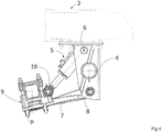
Figure 4 is a side elevation view of the suspension at its maximum height position. -
Figure 5 is a partially sectioned side elevation view of the suspension, in which a first embodiment of the constraining means between the suspension arm and the fastening member is highlighted. -
Figure 6 is a partially sectioned side elevation view of the suspension, in which a second embodiment of the constraining means between the suspension arm and the fastening member is highlighted. - With reference to the figures cited, an oil-
hydraulic suspension 1 for connecting a chassis, and particularly alongitudinal member 2 of the chassis, to anaxle 3 bearing the wheels of a vehicle is shown. - The oil-
hydraulic suspension 1 comprises a suitably shaped main load-bearingbody 4 that is coupleable to thelongitudinal member 2, an oil-hydraulic suspension cylinder 5, the upper end of which is joined in a hinged manner by means of ahinge axis 6 to the main load-bearingbody 4, alongitudinal arm 7 for connecting theaxle 3 to the main load-bearingbody 4, positioned below the oil-hydraulic suspension cylinder 5 and joined in a hinged manner by means of ahinge axis 8 to the main load-bearingbody 4, and fastening means for fastening the connectingarm 7 to theaxle 3. - The fastening means 9 comprises a fastening
member 9 to which the lower end of thesuspension cylinder 5 is joined in a hinged manner by means of ahinge axis 10. - The oil-
hydraulic suspension 1 advantageously comprises constraining means between the fasteningmember 9 and the connectingarm 7. - The fastening
member 9 is advantageously made up of aplate 11 that engages along alongitudinal section 12 of the connectingarm 7. - More specifically, the
plate 11 and thelongitudinal section 12 of the connectingarm 7 are in contact along respective longitudinal plane surfaces. - The constraining means locks the
plate 11 in contact along thelongitudinal section 12 of the connectingarm 7. - The constraining means thus transmits forces directly from the
suspension cylinder 5 to the connectingarm 7. - With reference to the embodiment illustrated in
Figure 5 , the constraining means between the fasteningmember 9 and the connectingarm 7 comprises for example aperpendicular connector pin 21 between the connectingarm 7 and theplate 11. With reference to the embodiment illustrated inFigure 6 , the constraining means between the fasteningmember 9 and the connectingarm 7 comprises for example aprojection 22 from the end of the connectingarm 7, saidprojection 22 being engaged with anabutment 23 on theplate 11. Theprojection 22 and theabutment 23 are positioned at the ends of the connectingarm 7 and theplate 11, respectively, opposite the ends having thehinge axes body 4 and to thesuspension cylinder 5, respectively. - The inclination of the axis of the
suspension cylinder 5 is such as to transmit, to the connectingarm 7, by virtue of the rigid constraint with thefastening member 9, a force having a significant axial traction component acting upon the connectingarm 7. - The longitudinal axis of the
suspension cylinder 5 is arranged coplanar with a longitudinal median plane of the connectingarm 7 perpendicular to thehinge axes longitudinal member 2 of the chassis of the vehicle. - The main load-bearing
body 4, thesuspension cylinder 5, and theplate 11 locked on the connectingarm 7 form an arch structure with threehinges Figures 2 ,3 and4 , the line of action of thesuspension cylinder 5 intersects in P the vertical line of action of the load on the wheel, always substantially within the connectingarm 7 for connection to theaxle 3. - Given that the forces transmitted act directly on the connecting
arm 7 located vertically below thesuspension cylinder 5, the twisting moment on the assembly made up of theaxle 3 and thefastening member 9 is reduced to a minimum. - The
plate 11 has aseat 13 for engaging theaxle 3 on the upper longitudinal side opposite the lower side for engagement to the connectingarm 7. - The lower portion of the
axle 3 is housed within theengagement seat 13. - The
plate 11 supports thehinge axis 10 with thesuspension cylinder 5 above and arranges it between theaxle 3 and the main load-bearingbody 4. - The
hinge axis 10 of theplate 11 with thesuspension cylinder 5 is contained in aplane 14 intersecting theaxle 3 and parallel to amedian plane 15 of theplate 11 parallel to thehinge axes - The fastening means for fastening the connecting
arm 7 to theaxle 3 further comprises acounter plate 16 that has aseat 17 for engaging theaxle 3, and tie-rods 18 for securing theaxle 3 between theplate 11 and thecounter plate 16. - The
engagement seat 17 in thecounter plate 16 receives the upper portion of theaxle 3 and, as in the case of theplate 11, it is provided with through holes for passage of the tie-rods 18, which, by means of fasteningnuts 19, secure theaxle 3 between thecounter plate 16 and theplate 11. - Lastly, as the tie-
rods 18 are U-shaped, the fastening means for fastening the connectingarm 7 to theaxle 3 comprises aninsert 20 having adjustment portions connected, on one end, to the flat side of the connectingarm 7 opposite the one for engagement with theplate 11, and on the other end, to the internal side of the arcuate section of the tie-rods 18. - The main load-bearing
body 4 has acircular opening 24 of a suitable diameter that receives atube 25 welded to the main load-bearingbody 4 so as to contribute to the rigidity of the chassis of the vehicle. Therefore, it will not be necessary to have the crossmembers of the chassis correspond with the fastening areas of the main load-bearing body of the suspension. In this manner, the choice for positioning the suspension with respect to the chassis involves only the functional requirements of the vehicle itself, without any influence on the vehicle's structure. - The structure thus realized for the
suspension 1 offers numerous advantages. - All the forces act upon the same plane, that is, the vertical plane parallel to the longitudinal axis of the vehicle and generally coincident with the median plane of the longitudinal member of the chassis. In this manner, said forces have no components or moments that could create local stresses in the structures of the suspension or the chassis of the vehicle.
- The suspension cylinder acts upon the main load-bearing body and therefore the longitudinal member of the chassis is not subject to concentrated forces.
- The suspension cylinder can be assembled in both the configuration shown, that is, with the stem connected to the fastening member and the chamber joined in a hinged manner to the main load-bearing body, and with the stem joined in a hinged manner to the main load-bearing body and the chamber connected to the fastening member. The first solution makes it possible to reduce the length and relative movements of the supply lines with respect to the chassis of the vehicle with a reduction of the effects of fatigue on these lines and the relative fittings. The second solution makes it possible to have the cylinder stems and the relative oil-hydraulic sealing members arranged in a position protected from impacts and from aggressive environmental agents.
- The design solution adopted for the fastening member, that is to say, a plate that incorporates the hinge for joining the suspension cylinder, offers virtually complete freedom in the realization of the connection of the axle to the suspension. The constraining means entails stable coupling of the fastening member with the connecting arm, and therefore for any adjustments of the alignment of the hinge axes with respect to the geometric axis of the vehicle, the hinges used are adjustable hinges with a cam system already known in the state of the art.
- Thus conceived, the oil-hydraulic suspension is susceptible to numerous modifications and variants, all of which falling within the scope of the inventive concept. Moreover, all details may be replaced with other technically equivalent elements.
- The materials used, as well as the dimensions, may in practice be of any type, according to needs and the state of the art.
Claims (13)
- An oil-hydraulic suspension (1) for connecting a chassis to an axle (3) of a vehicle, and comprising a main load-bearing body (4) that is coupleable to the chassis of the vehicle, an oil-hydraulic suspension cylinder (5) hinged to the main load-bearing body (4), a connecting arm (7) for connecting the axle (3) to the main load-bearing body (4) hinged to the main load-bearing body (4), and fastening means for fastening the connecting arm (7) to the axle (3), said fastening means comprising a fastening member (9) to which said suspension cylinder (5) is hinged, there also being provided a constraining means between said fastening member (9) and said connecting arm (7), and characterized in that it is configured so that the line of action of said suspension cylinder (5) intersects the vertical line of action of the load on the wheel, always substantially within said connecting arm (7).
- The oil-hydraulic suspension (1) for suspending a chassis from an axle of a vehicle according to claim 1, characterized in that characterized in that said fastening member (9) is made up of a plate (11) that engages along a longitudinal section (12) of said connecting arm (7).
- The oil-hydraulic suspension (1) for suspending a chassis from an axle of a vehicle according to the preceding claim, characterized in that said constraining means locks said plate (11) along said longitudinal section (12) of said connecting arm (7).
- The oil-hydraulic suspension (1) for suspending a chassis from an axle of a vehicle according to claim 1, characterized in that the longitudinal axis of said suspension cylinder (5) is arranged coplanar with a longitudinal median plane of said connecting arm (7).
- The oil-hydraulic suspension (1) for suspending a chassis from an axle of a vehicle according to claim 2, characterized in that said main load-bearing body (4), said suspension cylinder (5) and said plate (11), which is locked along said longitudinal section (12) of said connecting arm (7), form an arch structure with three hinges.
- The oil-hydraulic suspension (1) for suspending a chassis from an axle of a vehicle according to the preceding claim, characterized in that said plate (11) has a seat (13) for engaging the axle (3) on the side opposite the side for engagement to said connecting arm (7).
- The oil-hydraulic suspension (1) for suspending a chassis from an axle of a vehicle according to the preceding claim, characterized in that the hinging of said plate (11) with said suspension cylinder (5) is found on the same side of the plate (11) where said seat (13) for engagement with the axle (3) is provided.
- The oil-hydraulic suspension (1) for suspending a chassis from an axle of a vehicle according to claim, 1 characterized in that said constraining means comprises a connector pin (21).
- The oil-hydraulic suspension (1) for suspending a chassis from an axle of a vehicle according to claim, 1 characterized in that said constraining means comprises a projection (22) engaged with an abutment (23).
- The oil-hydraulic suspension (1) for suspending a chassis from an axle of a vehicle according to claim 1, characterized in that said main load-bearing body (4) has an opening (24) in which a tube (25) for structural stiffening is fastened.
- The oil-hydraulic suspension (1) for suspending a chassis from an axle of a vehicle according to claim 1, characterized in that at least one of the hingings comprises an adjustable hinge with a cam system.
- A vehicle characterized in that it comprises an oil-hydraulic suspension (1) according to any one of the preceding claims, wherein said suspension (1) is mounted with the longitudinal axis of the suspension cylinder (5) coplanar with a longitudinal median plane of the connecting arm (7) and with a longitudinal median plane of a longitudinal member (2) of the chassis of the vehicle.
- The vehicle according to the preceding claim, characterized in that the hinging axis (10) between said suspension cylinder (5) and said plate (11) is contained in a plane (14) intersecting the axle (3) and parallel to a longitudinal median plane (15) of the plate (11).
Applications Claiming Priority (1)
| Application Number | Priority Date | Filing Date | Title |
|---|---|---|---|
| ITUA2016A001400A ITUA20161400A1 (en) | 2016-03-07 | 2016-03-07 | HYDRAULIC SUSPENSION FOR VEHICLES |
Publications (1)
| Publication Number | Publication Date |
|---|---|
| EP3216631A1 true EP3216631A1 (en) | 2017-09-13 |
Family
ID=56203528
Family Applications (1)
| Application Number | Title | Priority Date | Filing Date |
|---|---|---|---|
| EP17157691.1A Withdrawn EP3216631A1 (en) | 2016-03-07 | 2017-02-23 | Oil-hydraulic suspension for vehicles |
Country Status (2)
| Country | Link |
|---|---|
| EP (1) | EP3216631A1 (en) |
| IT (1) | ITUA20161400A1 (en) |
Cited By (5)
| Publication number | Priority date | Publication date | Assignee | Title |
|---|---|---|---|---|
| CN110103656A (en) * | 2018-09-17 | 2019-08-09 | 丰疆智能科技股份有限公司 | Port logistics vehicle |
| US10967695B2 (en) * | 2018-03-02 | 2021-04-06 | Blueline Mfg., Co. | Steerable suspension system |
| US11541711B1 (en) * | 2020-04-07 | 2023-01-03 | Ronny Dean Eaves | Multi-travel suspension trailer |
| IT202100017705A1 (en) * | 2021-07-05 | 2023-01-05 | R P F S P A | RIGID AXLE WITH HYDRAULIC SUSPENSION FOR A TRAILER OF A VEHICLE WITH A BEARING FRAME CONNECTING TO THE CHASSIS OF THE SAID TRAILER |
| US20230109453A1 (en) * | 2021-10-04 | 2023-04-06 | Holcombe CVI, LLC | Retractably Extendable Trailing Axle |
Citations (12)
| Publication number | Priority date | Publication date | Assignee | Title |
|---|---|---|---|---|
| US4415179A (en) * | 1981-04-15 | 1983-11-15 | Marinelli Joseph A | Axle and air bag suspension |
| GB2257670A (en) * | 1991-07-18 | 1993-01-20 | Rubery Owen Rockwell Ltd | Vehicle tracking adjustment. |
| FR2737443A1 (en) * | 1995-08-01 | 1997-02-07 | Europ Semi Remorques | Suspension for motor vehicle trailers and semi-trailers of commercial vehicles - has axle fixed to trailing or leading lower arms, with inclined shock absorbers as upper arms |
| DE29713996U1 (en) * | 1997-08-06 | 1998-12-10 | Trenkamp & Gehle GmbH, 49413 Dinklage | Device for connecting the axle body of a wheel axle, in particular a commercial vehicle, to the trailing arms of an axle support |
| NL1009580C2 (en) * | 1998-07-07 | 2000-01-10 | Weweler Nv | Clamp to secure vehicle axle body to longitudinal suspension arm with adjustment to accommodate axles over small range of cross-sectional dimensions with no mechanical play |
| GB2349856A (en) * | 1999-05-10 | 2000-11-15 | Meritor Heavy Vehicle Sys Ltd | Vehicle air suspension |
| WO2003068540A1 (en) * | 2002-02-14 | 2003-08-21 | Bpw Bergische Achsen Kg | Vehicle axis |
| US20050023788A1 (en) * | 2003-05-06 | 2005-02-03 | Svartz Bjorn O. | Vehicular spring suspension |
| DE202007006610U1 (en) * | 2007-05-09 | 2007-07-12 | B. Strautmann & Söhne GmbH u. Co. KG | Hydraulic shaft and axle suspension for a trailer, to carry harvested animal fodder, has control of the hydro-cylinders through valves to be switched for adjustment during loading/unloading |
| EP2263891A1 (en) * | 2008-04-15 | 2010-12-22 | Kubota Corporation | Suspension system |
| US20130181422A1 (en) * | 2012-01-13 | 2013-07-18 | Nicholas Eveley | Trailing beam mounting and alignment apparatus |
| EP2860051A1 (en) * | 2013-10-10 | 2015-04-15 | CLAAS Saulgau GmbH | Axle device for an agricultural trailer and agricultural trailer |
-
2016
- 2016-03-07 IT ITUA2016A001400A patent/ITUA20161400A1/en unknown
-
2017
- 2017-02-23 EP EP17157691.1A patent/EP3216631A1/en not_active Withdrawn
Patent Citations (12)
| Publication number | Priority date | Publication date | Assignee | Title |
|---|---|---|---|---|
| US4415179A (en) * | 1981-04-15 | 1983-11-15 | Marinelli Joseph A | Axle and air bag suspension |
| GB2257670A (en) * | 1991-07-18 | 1993-01-20 | Rubery Owen Rockwell Ltd | Vehicle tracking adjustment. |
| FR2737443A1 (en) * | 1995-08-01 | 1997-02-07 | Europ Semi Remorques | Suspension for motor vehicle trailers and semi-trailers of commercial vehicles - has axle fixed to trailing or leading lower arms, with inclined shock absorbers as upper arms |
| DE29713996U1 (en) * | 1997-08-06 | 1998-12-10 | Trenkamp & Gehle GmbH, 49413 Dinklage | Device for connecting the axle body of a wheel axle, in particular a commercial vehicle, to the trailing arms of an axle support |
| NL1009580C2 (en) * | 1998-07-07 | 2000-01-10 | Weweler Nv | Clamp to secure vehicle axle body to longitudinal suspension arm with adjustment to accommodate axles over small range of cross-sectional dimensions with no mechanical play |
| GB2349856A (en) * | 1999-05-10 | 2000-11-15 | Meritor Heavy Vehicle Sys Ltd | Vehicle air suspension |
| WO2003068540A1 (en) * | 2002-02-14 | 2003-08-21 | Bpw Bergische Achsen Kg | Vehicle axis |
| US20050023788A1 (en) * | 2003-05-06 | 2005-02-03 | Svartz Bjorn O. | Vehicular spring suspension |
| DE202007006610U1 (en) * | 2007-05-09 | 2007-07-12 | B. Strautmann & Söhne GmbH u. Co. KG | Hydraulic shaft and axle suspension for a trailer, to carry harvested animal fodder, has control of the hydro-cylinders through valves to be switched for adjustment during loading/unloading |
| EP2263891A1 (en) * | 2008-04-15 | 2010-12-22 | Kubota Corporation | Suspension system |
| US20130181422A1 (en) * | 2012-01-13 | 2013-07-18 | Nicholas Eveley | Trailing beam mounting and alignment apparatus |
| EP2860051A1 (en) * | 2013-10-10 | 2015-04-15 | CLAAS Saulgau GmbH | Axle device for an agricultural trailer and agricultural trailer |
Cited By (8)
| Publication number | Priority date | Publication date | Assignee | Title |
|---|---|---|---|---|
| US10967695B2 (en) * | 2018-03-02 | 2021-04-06 | Blueline Mfg., Co. | Steerable suspension system |
| CN110103656A (en) * | 2018-09-17 | 2019-08-09 | 丰疆智能科技股份有限公司 | Port logistics vehicle |
| US11541711B1 (en) * | 2020-04-07 | 2023-01-03 | Ronny Dean Eaves | Multi-travel suspension trailer |
| IT202100017705A1 (en) * | 2021-07-05 | 2023-01-05 | R P F S P A | RIGID AXLE WITH HYDRAULIC SUSPENSION FOR A TRAILER OF A VEHICLE WITH A BEARING FRAME CONNECTING TO THE CHASSIS OF THE SAID TRAILER |
| EP4116116A1 (en) * | 2021-07-05 | 2023-01-11 | R.P.F. S.p.A. | Rigid axle with hydraulic suspension for a trailer of a vehicle with a load-bearing frame connecting to the frame of said trailer |
| US20230109453A1 (en) * | 2021-10-04 | 2023-04-06 | Holcombe CVI, LLC | Retractably Extendable Trailing Axle |
| US11827072B2 (en) * | 2021-10-04 | 2023-11-28 | Holcombe CVI, LLC | Retractably extendable trailing axle |
| US12172488B2 (en) | 2021-10-04 | 2024-12-24 | Holcombe CVI, LLC | Retractably extendable trailing axle |
Also Published As
| Publication number | Publication date |
|---|---|
| ITUA20161400A1 (en) | 2017-09-07 |
Similar Documents
| Publication | Publication Date | Title |
|---|---|---|
| EP3216631A1 (en) | Oil-hydraulic suspension for vehicles | |
| US8333396B2 (en) | Top mount trailing arm suspension | |
| AU2010248944B2 (en) | Suspension system for heavy and vocational vehicles | |
| AU2013299961B2 (en) | Motor vehicle axle suspension with longitudinal leaf spring | |
| US5203585A (en) | Split-beam suspension system | |
| US20130001913A1 (en) | Trailing arm mounting bracket | |
| US10807430B2 (en) | Axle/suspension systems | |
| EP2398659B1 (en) | Support for pneumatic spring of wheel axle suspension. | |
| US20080084047A1 (en) | Suspension subassembly | |
| CN104661840B (en) | Reduced weight shaft connection assembly for vehicle suspension systems | |
| US8292313B2 (en) | Heavy-duty axle-to-beam connection | |
| US7520515B2 (en) | Steer axle suspension | |
| ES2772255T3 (en) | Pneumatic tandem axle suspension for a pair of rear axles of a vehicle, in particular a heavy goods vehicle | |
| CN102802970A (en) | Wheel carrier for a multi-link individual wheel suspension system | |
| US11565563B2 (en) | Suspension travel control system | |
| US20140197614A1 (en) | Wheel Axle Suspension | |
| US7188850B2 (en) | Beam axle suspension with diagonal link | |
| AU2015314403B2 (en) | Axle unit | |
| CN108556589A (en) | A kind of FSAE racing car stabilizer bar for realizing step-less adjustment | |
| US10046614B2 (en) | Reinforcing unit | |
| CN112272621B (en) | Suspension travel control system | |
| KR20130038689A (en) | Ctba improving torsion stiffness | |
| US10639954B2 (en) | Multi-link suspension system | |
| CN108688428B (en) | Torsion beam rear suspension | |
| CN107839824B (en) | Front suspension system of three-wheeled automobile |
Legal Events
| Date | Code | Title | Description |
|---|---|---|---|
| PUAI | Public reference made under article 153(3) epc to a published international application that has entered the european phase |
Free format text: ORIGINAL CODE: 0009012 |
|
| AK | Designated contracting states |
Kind code of ref document: A1 Designated state(s): AL AT BE BG CH CY CZ DE DK EE ES FI FR GB GR HR HU IE IS IT LI LT LU LV MC MK MT NL NO PL PT RO RS SE SI SK SM TR |
|
| AX | Request for extension of the european patent |
Extension state: BA ME |
|
| 17P | Request for examination filed |
Effective date: 20180307 |
|
| RBV | Designated contracting states (corrected) |
Designated state(s): AL AT BE BG CH CY CZ DE DK EE ES FI FR GB GR HR HU IE IS IT LI LT LU LV MC MK MT NL NO PL PT RO RS SE SI SK SM TR |
|
| 17Q | First examination report despatched |
Effective date: 20200407 |
|
| STAA | Information on the status of an ep patent application or granted ep patent |
Free format text: STATUS: THE APPLICATION IS DEEMED TO BE WITHDRAWN |
|
| 18D | Application deemed to be withdrawn |
Effective date: 20200818 |