EP3216626A1 - Pneumatic tire - Google Patents
Pneumatic tire Download PDFInfo
- Publication number
- EP3216626A1 EP3216626A1 EP15857826.0A EP15857826A EP3216626A1 EP 3216626 A1 EP3216626 A1 EP 3216626A1 EP 15857826 A EP15857826 A EP 15857826A EP 3216626 A1 EP3216626 A1 EP 3216626A1
- Authority
- EP
- European Patent Office
- Prior art keywords
- tread
- portions
- projecting
- land
- land portions
- Prior art date
- Legal status (The legal status is an assumption and is not a legal conclusion. Google has not performed a legal analysis and makes no representation as to the accuracy of the status listed.)
- Granted
Links
Images





Classifications
-
- B—PERFORMING OPERATIONS; TRANSPORTING
- B60—VEHICLES IN GENERAL
- B60C—VEHICLE TYRES; TYRE INFLATION; TYRE CHANGING; CONNECTING VALVES TO INFLATABLE ELASTIC BODIES IN GENERAL; DEVICES OR ARRANGEMENTS RELATED TO TYRES
- B60C11/00—Tyre tread bands; Tread patterns; Anti-skid inserts
- B60C11/03—Tread patterns
- B60C11/13—Tread patterns characterised by the groove cross-section, e.g. for buttressing or preventing stone-trapping
-
- B—PERFORMING OPERATIONS; TRANSPORTING
- B60—VEHICLES IN GENERAL
- B60C—VEHICLE TYRES; TYRE INFLATION; TYRE CHANGING; CONNECTING VALVES TO INFLATABLE ELASTIC BODIES IN GENERAL; DEVICES OR ARRANGEMENTS RELATED TO TYRES
- B60C11/00—Tyre tread bands; Tread patterns; Anti-skid inserts
- B60C11/03—Tread patterns
- B60C11/11—Tread patterns in which the raised area of the pattern consists only of isolated elements, e.g. blocks
-
- B—PERFORMING OPERATIONS; TRANSPORTING
- B60—VEHICLES IN GENERAL
- B60C—VEHICLE TYRES; TYRE INFLATION; TYRE CHANGING; CONNECTING VALVES TO INFLATABLE ELASTIC BODIES IN GENERAL; DEVICES OR ARRANGEMENTS RELATED TO TYRES
- B60C11/00—Tyre tread bands; Tread patterns; Anti-skid inserts
- B60C11/03—Tread patterns
- B60C11/13—Tread patterns characterised by the groove cross-section, e.g. for buttressing or preventing stone-trapping
- B60C11/1369—Tie bars for linking block elements and bridging the groove
-
- B—PERFORMING OPERATIONS; TRANSPORTING
- B60—VEHICLES IN GENERAL
- B60C—VEHICLE TYRES; TYRE INFLATION; TYRE CHANGING; CONNECTING VALVES TO INFLATABLE ELASTIC BODIES IN GENERAL; DEVICES OR ARRANGEMENTS RELATED TO TYRES
- B60C11/00—Tyre tread bands; Tread patterns; Anti-skid inserts
- B60C11/03—Tread patterns
- B60C11/13—Tread patterns characterised by the groove cross-section, e.g. for buttressing or preventing stone-trapping
- B60C11/1307—Tread patterns characterised by the groove cross-section, e.g. for buttressing or preventing stone-trapping with special features of the groove walls
- B60C2011/1338—Tread patterns characterised by the groove cross-section, e.g. for buttressing or preventing stone-trapping with special features of the groove walls comprising protrusions
-
- Y—GENERAL TAGGING OF NEW TECHNOLOGICAL DEVELOPMENTS; GENERAL TAGGING OF CROSS-SECTIONAL TECHNOLOGIES SPANNING OVER SEVERAL SECTIONS OF THE IPC; TECHNICAL SUBJECTS COVERED BY FORMER USPC CROSS-REFERENCE ART COLLECTIONS [XRACs] AND DIGESTS
- Y02—TECHNOLOGIES OR APPLICATIONS FOR MITIGATION OR ADAPTATION AGAINST CLIMATE CHANGE
- Y02T—CLIMATE CHANGE MITIGATION TECHNOLOGIES RELATED TO TRANSPORTATION
- Y02T10/00—Road transport of goods or passengers
- Y02T10/80—Technologies aiming to reduce greenhouse gasses emissions common to all road transportation technologies
- Y02T10/86—Optimisation of rolling resistance, e.g. weight reduction
Definitions
- the present invention relates to a pneumatic tire having a tread formed with a plurality of line grooves, particularly to a tread structure of a pneumatic tire.
- the line grooves promote drainage to thereby secure a frictional force (wet grip performance) even on a wet road surface.
- Patent Document 1 discloses a tread structure wherein side walls on both sides of each circumferential groove extending in the tread circumferential direction are both provided with projecting portions projecting into the groove, and the opposed projecting portions make contact with each other at the time of grounding.
- Patent Document 2 discloses a tread structure wherein a wall surface on one side of a communication portion where a transverse groove extending in the tread width direction communicates with a circumferential groove is provided with a projection (projecting portion) projecting toward a wall surface on the other side.
- the deformation of the land portions and the deformation of the projecting portions due to the sliding contact may obstruct the draining property of the line grooves, resulting in a lowering in wet grip performance.
- the projection extends from the wall surface on one side to the vicinity of the wall surface on the other side, rigidity of the projection itself is poor, and the force with which the projection supports the land portions on both sides is weakened. As a result, the deformation of the land portions may obstruct the draining property and may lower the wet grip performance.
- the present invention has been made in consideration of the above-mentioned points. Accordingly, it is an object of the present invention to provide a pneumatic tire wherein a projecting portion, coming into contact with an opposed surface by compressive deformation of land portions due to grounding of a tread, firmly supports the land portions on both sides of a line groove, and suppresses deformation of the land portions, whereby rolling resistance can be reduced while maintaining the wet grip performance.
- the present invention provides a pneumatic tire having a tread formed with a plurality of land portions defined by a plurality of line grooves, wherein projecting portions are formed to project from both of opposed side surfaces of the land portions located adjacent to each other with the line groove therebetween toward each other, the projecting portions each being formed in that region of the land portion which is deeper than a tread surface, and closely opposed end surfaces of the projecting portions facing each other are both formed to be rough surfaces having a high frictional resistance.
- the present invention further provides a pneumatic tire having a tread formed with a plurality of land portions defined by a plurality of line grooves, wherein a projecting portion is formed to project from one of opposed side surfaces of the land portions located adjacent to each other with the line groove therebetween toward the other of the side surfaces, the projecting portion being formed in that region of the land portion which is deeper than a tread surface, and an end surface of the projecting portion and the side surface opposed to the end surface, which are closed to each other, are both formed to be rough surfaces having a high frictional resistance.
- the rough surface may include a multiplicity of tapered-off projections formed on a flat surface.
- the angle of a tapered-off tip of the projection is around 90 degrees.
- the line grooves are circumferential grooves extending in a tread circumferential direction, and the projecting portions are formed to project into the circumferential grooves.
- the line grooves are transverse grooves extending in a tread width direction, and the projecting portions are formed to project into the transverse grooves.
- the line grooves are circumferential grooves extending in a tread circumferential direction and transverse grooves extending in a tread width direction, and the projecting portions are formed to project into the circumferential grooves and the transverse grooves.
- a pneumatic tire having a tread formed with a plurality of land portions defined by a plurality of line grooves
- projecting portions project from both of opposed side surfaces of the land portions located adjacent to each other with the line groove therebetween toward each other.
- the land portions undergo compressive deformation due to grounding
- the projecting portions projecting from both of the opposed side surfaces of the adjacent land portions toward each other come close to each other, and the closely opposed end surfaces make contact with each other.
- the end surfaces contacting each other are both formed with rough surfaces having a high frictional resistance, they engage each other upon contact and their slippage is restrained, whereby the projecting portions contacting each other can together firmly support the land portions on both sides thereof. Therefore, compressive deformation of the land portions is suppressed, and falling-down (collapsing) of the land portions is prevented. Accordingly, the rigidity of the land portions is maintained, whereby uneven wear of the tread is restrained, energy loss due to hysteresis loss arising from the deformation can be suppressed, and rolling resistance can be reduced.
- the projecting portion is formed in that region of the land portion which is deeper than the tread surface and deformation of the land portions and deformation of the projecting portions due to sliding contact are restrained, the draining property of the line grooves is secured, and wet grip performance can be maintained.
- projecting portions are formed to project from one of opposed side surfaces of the land portions located adjacent to each other with the line groove therebetween toward the other side surface.
- the projecting portion projecting from one of the opposed side surfaces of the adjacent land portions toward the other side surface comes closer to, and makes contact with the other side surface opposed.
- the end surface of the projecting portion and the side surface opposed to the end surface making contact with each other are both formed with rough surfaces having a high frictional resistance, they engage each other upon contact, and slippage thereat is restrained. This ensures that the projecting portions making contact can firmly support the land portions on both sides thereof. Accordingly, compressive deformation of the land portions is suppressed, falling-down (collapsing) of the land portions is prevented, and rigidity of the land portions is maintained, whereby uneven wear is restrained, energy loss due to hysteresis loss arising from the deformation can be suppressed, and rolling resistance can be reduced.
- the projecting portion is formed in that region of the land portion which is deeper than the tread surface and the deformation of the land portions and the deformation of the projecting portions due to sliding contact are restrained, the draining property of the line grooves is secured, and wet grip performance can be maintained.
- the rugged patterns formed by the projections engage each other, to increase frictional resistance and minimize slippage thereat.
- the projecting portions making contact can firmly support the land portions on both sides thereof, uneven wear of the tread due to deformation can be restrained, and rolling resistance can be reduced.
- the angle of the tapered-off tips of the projections is around 90 degrees, so that the rugged patterns formed by the projections firmly engage each other to restrain slippage thereat assuredly.
- the projecting portions making contact can firmly support the land portions on both sides thereof, uneven wear due to deformation can be restrained more securely, and rolling resistance can be further reduced.
- the projecting portions are formed to project into circumferential grooves. Therefore, particularly at the time of cornering, falling-down (collapsing) of the land portions is restrained, uneven wear can be restrained, and rolling resistance can be reduced.
- the projecting portions are formed to project into transverse grooves. Therefore, particularly at the time of acceleration or deceleration, falling-down (collapsing) of the land portions is restrained, uneven wear of the tread can be restrained, and rolling resistance can be reduced.
- the projecting portions are formed to project into circumferential grooves and transverse grooves. Therefore, both at the time of cornering and at the time of acceleration or deceleration of a vehicle, falling-down (collapsing) of the land portions is restrained, uneven wear of the tread can be restrained, and rolling resistance can be reduced.
- FIGS. 1 to 12 A first embodiment of the present invention is illustrated in FIGS. 1 to 12 .
- the first embodiment relates to a tread of a pneumatic tire which is provided with projecting portions in circumferential grooves extending in a tread circumferential direction A, and Example 1 as one example thereof will be described based on FIGS. 1 to 4 .
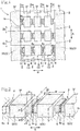
- a tread 1 of a pneumatic tire of Example 1 forms a tread pattern wherein four circumferential grooves 2 extending in the tread circumferential direction A are formed at regular intervals, and a multiplicity of transverse grooves 3 extending in a tread width direction B between the outside circumferential grooves 2, 2 on both outer sides in regard of the tread width direction B are formed at regular intervals over the whole circumference.
- the four circumferential grooves 2 have the same groove width Dw, and, also, the transverse grooves 3 all have the same groove width Dc (see FIG. 1 ).
- the circumferential grooves 2 and the transverse grooves 3 are both line grooves having groove bottoms 1b at the same depth.
- the tread 1 is formed with a multiplicity of land portions 5 defined by the four circumferential grooves 2 and the multiplicity of transverse grooves 3.
- the land portions 5 include a multiplicity of rectangular parallelepiped inside land portions 5I formed on the inner sides of the outside circumferential grooves 2, 2, and outside land portions 5S, 5S formed continuously in an annular form on the outer sides of the outside circumferential grooves 2, 2.
- the inside land portion 5I is a rectangular parallelepiped having a thickness T from the groove bottom 1b in a tire radial direction (corresponding to the depth of the grooves), a width length C in the tread circumferential direction, and a width length W in the tread width direction.
- projecting portions 6, 6 are formed to project from both of opposed side surfaces of the land portions 5, 5 located adjacent to each other with the circumferential groove 2 therebetween toward each other.
- the projecting portion 6 projecting in the tread width direction B is formed to project in a quadrangular prismatic shape wherein an inside surface is located at a position higher than the groove bottom 1b and an outside surface is located at a position lower than a tread surface (outer surface) 5f of the land portion 5.
- the projecting portions 6, 6 facing each other are formed in symmetry to project by the same projection amount w until they come close to each other.
- the projecting portion 6 projects into an intermediate depth region of the circumferential groove 2, in a quadrangular prismatic shape having a thickness t in the tire radial direction, a width length c in the tread circumferential direction, and a projection amount w in the tread width direction.
- an outside surface (outer surface) of the projecting portion 6 is located at a position deeper by a spacing d1 than the tread surface 5f, which is the outer surface of the land portion 5 in regard of the tire radial direction, in the circumferential groove 2, and an inside surface (inner surface) of the projecting portion 6 is located at a position higher by a spacing d2 than the groove bottom 1b of the circumferential groove 2.
- side surfaces of the projecting portion 6 are located at positions deviated to the inner sides by a distance e from both ends in regard of the tire circumferential direction of that projection side surface of the inside land portion 5I from which the projecting portion 6 projects.
- the projecting portion 6 is formed to project in the quadrangular prismatic shape, from the land portion 5 into the circumferential groove 2.
- closely opposed end surfaces 6s, 6s of the projecting portions 6, 6 projecting from the opposed side surfaces of the land portions 5, 5 located adjacent to each other with the circumferential groove 2 therebetween are both formed to be rough surfaces having a high frictional resistance.
- Example 1 as shown in enlarged form in FIG. 3 , the end surface 6s of the projecting portion 6 forms a rough surface wherein quadrangular pyramidal minute projections 7 are arranged in a matrix pattern.
- the height of the quadrangular pyramid of the projection 7 is h and the angle of the tapered-off tip of the projection 7 is represented by an angle ⁇ formed between opposed triangular side surfaces of the quadrangular pyramid
- the height h of the projection 7 in Example 1 is 2.0 mm
- the tip angle ⁇ is approximately 90 degrees.
- Such a rough surface can be formed at the end surface of the projecting portion 6 by, for example, a method in which a belt-shaped member formed with a rough surface is preliminarily produced and it is adhered to the end surface of the projecting portion 6.
- the tread 1 in Example 1 has the structure as described above, and its state, when the land portions 5 are grounded and a load F is exerted on the tread surface 5f, is schematically illustrated in FIG. 4 .
- the land portions 5 undergo compressive deformation by receiving the load F on the tread surface 5f.
- the four side surfaces of the land portion 5 are swelled at their central portions under the influence of the load F, the projecting portions 6, 6 formed to project from the opposed side surfaces of the land portions 5, 5 located adjacent to each other with the circumferential groove 2 therebetween come close to each other, and the opposed end surfaces 6s, 6s of the projecting portions 6, 6 make contact with each other.
- the end surfaces 6s, 6s making contact with each other are formed to be rough surfaces wherein the quadrangular pyramidal minute projections 7 are arranged in a matrix pattern, rugged patterns composed of the projections 7 engage each other, whereby slipping is restrained. Therefore, the projecting portions 6, 6 making contact with each other can together firmly support the land portions 5, 5 on both sides thereof.
- the projecting portion 6 is located in an intermediate depth region of the circumferential groove 2. As shown in FIG. 4 , when the land portions 5 are grounded and the opposed projecting portions 6, 6 make contact with each other in an integral manner, spaces permitting drainage are formed on the upper and lower sides of the projecting portions 6, 6 making contact with each other within the circumferential groove 2.
- the land portions 5 do not fall down (collapse) into the circumferential groove 2 to hamper drainage.
- the end surfaces 6s, 6s of the projecting portions 6, 6 making contact with each other are prevented from slipping, by the engagement of the rugged patterns formed by the projections 7. Therefore, a situation in which the end surfaces 6s, 6s slip on each other to project to the upper and lower sides, thereby blocking the spaces formed on the upper and lower sides of the projecting portions 6, 6 and spoiling the draining property can be prevented from occurring. Consequently, draining property of the circumferential grooves 2 is secured, and wet grip performance can be enhanced.
- the pneumatic tire of Example 1 has a tire size of 315/70R22.5, and the tread has a tread pattern wherein four circumferential grooves 2 extending in the circumferential direction with a groove width Dw of 10 mm are arranged in the tread width direction, and a multiplicity of transverse grooves 3 extending in the tread width direction with a groove width Dc of 10 mm are arranged in the tread circumferential direction, to form a multiplicity of land portions 5 defined by the circumferential grooves 2 and the transverse grooves 3.
- the land portions 5 each have a rectangular parallelepiped shape with a thickness T in the tire radial direction of 20 mm, a width length C in the tread circumferential direction of 60 mm, and a width length W in the tread width direction of 35 mm.
- the pneumatic tires of Prior Art Examples 1 and 2 also have the same tire size as that in Example 1, and their treads have the same tread pattern as that in Example 1.
- Prior Art Example 1 the land portions are not formed with the projecting portions, and in Prior Art Example 2, the land portions are formed with the same projecting portions as those of Example 1.
- the projecting portion 6 in Example 1 has a configuration wherein the thickness t in the tire radial direction is 14 mm, the width length c in the tread circumferential direction is 50 mm, the projection amount w in the tread width direction is 4.8 mm, the spacing d1 between the tread surface 5f and the upper surface of the projecting portion 6 is 3 mm, the spacing d2 between the groove bottom 1b and the lower surface of the projecting portion 6 is 3 mm, and the distance e from both ends in regard of the tread circumferential direction of that projection side surface of the inside land portion 5I from which the projecting portion 6 projects to the side surfaces of the projecting portion 6 is 5 mm.
- the end surfaces 6s of the projecting portions 6 in Example 1 are formed with rough surfaces wherein quadrangular pyramidal minute projections 7 are arranged in a matrix pattern
- the end surfaces of the projecting portions in Prior Art Example 2 are not formed with rough surfaces but formed to be simple flat surfaces.
- Example 1 The pneumatic tires of Example 1 and Prior Art Examples 1 and 2 as above were put to performance tests of rolling resistance performance and wet grip performance, and the evaluation results are set forth in Table 1.
- the rolling resistance test was measured by the force method according to the international standard International Organization for Standardization (ISO) 28580.
- the evaluation results of the rolling resistance coefficient RRC shown in Table 1 were obtained by a method wherein with respect to rolling resistance coefficient RRC obtained by dividing the measured value of rolling resistance by load, the reciprocal of the rolling resistance coefficient RRC is used, and is expressed in index while taking the value for Prior Art Example 1 as 100.
- a higher value of this index means a lower rolling resistance.
- the wet grip test was measured by the passenger car method according to the international standard ISO 15222.
- the evaluation results of the wet grip index shown in Table 1 are measured values of wet grip, expressed in index while taking the value for Prior Art Example 1 as 100.
- Example 1 wherein the end surfaces 6s of the projecting portions 6 were rough surfaces, the rolling resistance coefficient RRC was 133 and the wet grip index was 110, which shows further enhancement of rolling resistance performance and wet grip performance as compared to Prior Art Example 2.
- Examples 2, 3, 4, and 5 have the same tread pattern as that in Example 1, wherein the circumferential grooves 2, transverse grooves 3 and land portions 5 are denoted by the same reference symbols as used in Example 1.
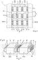
- a tread 11 of Example 2 has a configuration wherein projecting portions 16, 16, 16 corresponding to configurations obtained by trisecting the projecting portion 6 in Example 1 in the tread circumferential direction A project from side surfaces of the land portions 5 into the circumferential groove 2.
- Closely opposed end surfaces 16s, 16s of the projecting portions 16, 16 are both formed with rough surfaces having a high frictional resistance.
- the rough surfaces are configured in the same manner as the rough surfaces in Example 1.
- the opposed end surfaces 16s, 16s make contact with each other, the rough surfaces engage each other, and they do not slip on each other but together support the land portions 5. By this, rigidity of the land portions 5 is secured, and rolling resistance performance and wet grip performance are enhanced.
- Example 2 also, spaces are present between the three projecting portions 16, 16, 16 projecting from the land portion 5, so that draining property is superior to that in Example 1, and, particularly, enhanced wet grip performance is realized.
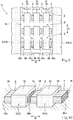
- a tread 21 of Example 3 has a configuration wherein two small-width projecting portions 26, 26 adjacent to each other in the circumferential direction A project from one of opposed side surfaces of land portions 5, 5 located adjacent to each other with the circumferential groove 2 therebetween, one large-width projecting portion 27 projects from the other of the opposed side surfaces, and closely opposed end surfaces 26s, 26s and end surface 27s of the two small-width projecting portions 26, 26 and the one large-width projecting portion 27 are formed with rough surfaces having a high frictional resistance.
- the rough surfaces are configured in the same manner as the rough surfaces in Example 1.
- Example 3 also, spaces are provided between the two small-width projecting portions 26, 26, so that draining property is superior to that in Example 1, and, particularly, enhanced wet grip performance is realized.
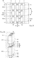
- a tread 31 of Example 4 has a configuration wherein a projecting portion 36 is formed to project from one of opposed side surfaces of land portions 5, 5 located adjacent to each other with the circumferential groove 2 therebetween toward the other of the side surfaces.
- An end surface 36s of the projecting portion 36 and an opposed surface 5s as a side surface of the land portion 5 opposed to the end surface 36s, which are close to each other, are both formed to be rough surfaces having a high frictional resistance.
- the rough surfaces are configured in the same manner as the rough surfaces in Example 1.
- a tread 41 of Example 5 has a configuration wherein two small-width projecting portions 46, 46 adjacent to each other in the circumferential direction A project from one of opposed side surfaces of land portions 5, 5 located adjacent to each other with the circumferential groove 2 therebetween toward the other of the side surfaces, and one small-width projecting portion 47 projects from the other of the side surfaces toward the one of the side surfaces, into a space between the two small-width projecting portions 46, 46.
- An end surface 46s of the small-width projecting portion 46 and an opposed surface 5s as a side surface of the land portion 5 opposed to the end surface 46s, which are close to each other, are both formed to be rough surfaces having a high frictional resistance.
- an end surface 47s of the small-width projecting portion 47 and an opposed surface 5s as a side surface of the land portion 5 opposed to the end surface 47s are both formed to be rough surfaces having a high frictional resistance.
- the rough surfaces are configured in the same manner as the rough surfaces in Example 1.
- Examples 6, 7, 8, 9, and 10 according to a second embodiment wherein projecting portions are provided in transverse grooves extending in a tread width direction in a tread of a pneumatic tire are illustrated in FIGS. 13 to 22 , and will be described below.
- Examples 6, 7, 8, 9, and 10 have the same tread pattern as in Example 1, and the circumferential grooves 2, transverse grooves 3, and land portions 5 are denoted by the same reference symbols as used in Example 1.
- a tread 51 of Example 6 has a configuration wherein projecting portions 56, 56 are formed to project from both of opposed side surfaces of inside land portions 5I, 5I located adjacent to each other with the transverse groove 3 therebetween toward each other.
- the projecting portion 56 projecting in the circumferential direction is formed to project in a quadrangular prismatic shape into a region that is higher than the groove bottom 1b and lower than the tread surface (outer surface) 5f of the land portion 5.
- the projecting portions 56, 56 facing each other are formed in symmetry to project by the same projection amount c until they come close to each other.
- the projecting portion 56 projects to an intermediate depth position in the transverse groove 3, in a quadrangular prismatic shape having a thickness t in the tire radial direction, a width length w in the tread width direction, and a projection amount c in the tread circumferential direction.
- an outside surface (outer surface) of the projecting portion 56 is located at a position deeper by a spacing d1 than the tread surface 5f of the land portion 5 in the tire redial direction in the transverse groove 3, and an inside surface (inner surface) of the projecting portion 56 is located at a depth position higher by a spacing d2 than the groove bottom 1b of the transverse groove 3.
- side surfaces of the projecting portion 56 are located at positions deviated toward the inner sides by a distance e from both ends in regard of the tire width direction of that projection side surface of the inside land portion 5I from which the projecting portion 56 projects.
- the projecting portion 56 is formed to project in a quadrangular prismatic shape from the land portion 5 into the transverse groove 3.
- closely opposed end surfaces 56s, 56s of the projecting portions 56, 56 projecting from opposed side surfaces of the land portions 5, 5 located adjacent to each other with the transverse groove 3 therebetween are both formed to be rough surfaces having a high frictional resistance.
- Example 6 the end surface 56s of the projecting portion 56 forms a rough surface wherein quadrangular pyramidal minute projections 7 are arranged in a matrix pattern, like the end surface 6s of the projecting portion 6 in Example 1, as depicted in FIG. 3 .
- the land portions 5 when the land portions 5 are grounded and a load F is exerted on the tread surface 5f, the land portions 5 undergo compressive deformation, the projecting portions 56, 56 formed to project from opposed side surfaces of the land portions 5, 5 located adjacent to each other with the transverse groove 3 therebetween come close to each other, the rough surfaces of the opposed end surfaces 56s, 56s of the projecting portions 56, 56 make contact with each other, the rugged patterns formed by the projections engage each other, whereby slipping is restrained, and the projecting portions 56, 56 making contact with each other can together firmly support the land portions 5, 5 on both sides thereof.
- the pneumatic tire of Example 6 has a tire size of 315/70R22.5, like in Example 1, and the tread pattern of the same size is configured.
- the projecting portion 56 of Example 6 has a configuration wherein the thickness t in the tire radial direction is 14 mm, the width length w in the tread circumferential direction is 25 mm, the projection amount c in the tread width direction is 4.8 mm, the spacing d1 between the tread surface 5f and the upper surface of the projecting portion 56 is 3 mm, the spacing d2 between the groove bottom 1b and the lower surface of the projecting portion 56 is 3 mm, and the distance e from both ends in regard of the tread width direction of that projection side surface of the inside land portion 5I from which the projecting portion 56 projects to the projecting portion 56 is 5 mm.
- the pneumatic tire of Prior Art Example 4 has a configuration wherein the same projecting portions as above are formed to project from both of opposed side surfaces of the land portions located adjacent to each other with the transverse groove therebetween toward each other.
- the end surfaces 56s of the projecting portions 56 in Example 6 are formed with rough surfaces wherein quadrangular pyramidal minute projections 7 are arranged in a matrix pattern
- the end surfaces of the projecting portions in Prior Art Example 4 are not formed with rough surfaces but formed to be simple flat surfaces.
- Example 6 wherein the end surfaces 56s of the projecting portions 56 were rough surfaces, the rolling resistance coefficient RRC was 130 and the wet grip index was 114, which shows further enhancement of rolling resistance performance and wet grip performance as compared to Prior Art Example 4.
- a tread 61 of Example 7 in the second embodiment wherein projecting portions are provided in transverse grooves of the tread has a configuration wherein projecting portions 66, 66, 66 obtained by trisecting the projecting portion 56 of Example 6 in the width direction project from side surfaces of the land portions 5 into the transverse groove 3.
- End surfaces 66s, 66s of the projecting portions 66, 66 that are closely opposed to each other are both formed with rough surfaces having a high frictional resistance.
- the three sets of opposed end surfaces 66s, 66s make contact with each other, the rough surfaces engage each other, and they do not slip on each other but together support the land portions 5. By this, rigidity of the land portions 5 is secured, and rolling resistance performance and wet grip performance are enhanced.
- Example 7 since spaces are present between the three projecting portions 66, 66, 66 projecting from the land portion 5, the draining property is superior to that in Example 6, and, particularly, enhanced wet grip performance is realized.
- a tread 71 of Example 8 has a configuration wherein two small-width projecting portions 76, 76 project from one of opposed side surfaces of land portions 5, 5 located adjacent to each other with the transverse groove 3 therebetween, one large-width projecting portion 77 projects from the other of the side surfaces, and closely opposed end surfaces 76s, 76s and end surface 77s of the two small-width projecting portions 76, 76 and one large-width projecting portion 77 are formed with rough surfaces having a high frictional resistance.
- the opposed end surfaces 76s, 76s and end surface 77s make contact with each other, the rough surfaces engage each other, and they do not slip on each other but together support the land portions 5. By this, rigidity of the land portions 5 is secured, and rolling resistance performance and wet grip performance are enhanced.
- Example 8 also, a space is present between the two small-width projecting portions 76, 76, so that the draining property is further better than in Example 6, and, particularly, enhanced wet grip performance is realized.
- a tread 81 of Example 9 has a configuration wherein a projecting portion 86 is formed to project from one of opposed side surfaces of land portions 5, 5 located adjacent to each other with the transverse groove 3 therebetween toward the other of the side surfaces.
- An end surface 86s of the projecting portion 86 and an opposed surface 5s as a side surface opposed to the end surface 86s, which are close to each other, are both formed to be rough surfaces having a high frictional resistance.
- the end surface 86s of the projecting portion 86 and the opposed surface 5s as the side surface opposed to the end surface 86s make contact with each other, the rough surfaces engage each other, and they do not slip on each other but together support the land portions 5.
- rigidity of the land portions 5 is secured, and rolling resistance performance and wet grip performance are enhanced.
- a tread 91 of Example 10 has a configuration wherein two small-width projecting portions 96, 96 project from one of opposed side surfaces of land portions 5, 5 located adjacent to each other with the transverse groove 3 therebetween toward the other of the side surfaces, and one small-width projecting portion 97 projects from the other of the side surfaces toward the one of the side surfaces, into a space between the two small-width projecting portions 96, 96.
- An end surface 96s of the small-width projecting portion 96 and an opposed surface 5s as a side surface opposed to the end surface 96s, which are close to each other, are both formed to be rough surfaces having a high frictional resistance.
- the three sets of the end surfaces 96s of the small-width projecting portions 96 and the opposed surfaces 5s as the side surfaces opposed to the end surfaces 96s make contact with each other, the rough surfaces engage each other, and they do not slip on each other but together support the land portions 5.
- rigidity of the land portions 5 is secured, and rolling resistance performance and wet grip performance are enhanced.
- a structure may be adopted wherein the projecting portions are not provided in some of the plurality of circumferential grooves 2.
- a structure may be adopted wherein the projecting portions are not provided in some of the plurality of transverse grooves 3.
- the rough surface at the end surface of the projecting portion is not limited to the one wherein quadrangular pyramidal minute projections are arranged; it is only required that surface roughness be great and a high frictional resistance be generated upon contact of the rough surfaces, and a minutely rugged surface shape may be adopted so long as engagement of the rugged patterns increases frictional resistance.
- circumferential grooves may not necessarily be parallel to the tire equatorial direction, and the transverse grooves may not necessarily be perpendicular to the tire equatorial direction; the grooves may be oblique at an angle relative to the tire equatorial direction.
Landscapes
- Engineering & Computer Science (AREA)
- Mechanical Engineering (AREA)
- Tires In General (AREA)
Abstract
Description
- The present invention relates to a pneumatic tire having a tread formed with a plurality of line grooves, particularly to a tread structure of a pneumatic tire.
- In a pneumatic tire having a tread formed with a plurality of land portions defined by a plurality of line grooves, the line grooves promote drainage to thereby secure a frictional force (wet grip performance) even on a wet road surface.
- However, when the land portions defined by the line grooves are grounded and the rigidity of the land portions cannot be maintained to undergo considerable compressive deformation and falling-down (collapsing), uneven wear of the tread is liable to occur, energy loss due to hysteresis loss arising from the deformation is increased, and rolling resistance is increased.
- In view of this, an example has been proposed wherein projecting portions are formed to project from a side surface of the land portion toward the land portion on the other side such that when the land portions are grounded, compressive deformation of the land portion causes the projecting portion to contact the land portion on the other side, and the contacting projecting portion supports the land portions on both sides, whereby rigidity of the land portions is maintained and deformation is suppressed (see, for example,
Patent Documents 1 and 2). -
- [Patent Document 1]
JP No. 2011-245996 A - [Patent Document 2]
JP No. 2012-11799 A -
Patent Document 1 discloses a tread structure wherein side walls on both sides of each circumferential groove extending in the tread circumferential direction are both provided with projecting portions projecting into the groove, and the opposed projecting portions make contact with each other at the time of grounding. - In addition,
Patent Document 2 discloses a tread structure wherein a wall surface on one side of a communication portion where a transverse groove extending in the tread width direction communicates with a circumferential groove is provided with a projection (projecting portion) projecting toward a wall surface on the other side. - In the tread structure described in
Patent Document 1, when the grounded land portions undergo compressive deformation and the projecting portions facing each other come close to each other to cause the end surfaces to contact each other, forces may not necessarily be exerted evenly, and the contact surfaces of the end surfaces may slip on each other (sliding contact). When the end surfaces make sliding contact with each other, the force with which the projecting portions support the land portions on both sides thereof is weakened, making it difficult to suppress the deformation of the land portions and to support them. Thus, it may become difficult to restrain uneven wear of the tread and an increase in rolling resistance. - In addition, the deformation of the land portions and the deformation of the projecting portions due to the sliding contact may obstruct the draining property of the line grooves, resulting in a lowering in wet grip performance.
- In the tread structure described in
Patent Document 2, when the grounded land portions undergo compressive deformation and the projection (projecting portion) contacts the wall surface on the other side, the contact surfaces may slip on each other, like in the structure described inPatent Document 1. As a result of the sliding contact, the force with which the projection supports the land portions on both sides thereof is weakened, and, eventually, it may become difficult to restrain uneven wear of the tread and an increase in rolling resistance. - Besides, since the projection extends from the wall surface on one side to the vicinity of the wall surface on the other side, rigidity of the projection itself is poor, and the force with which the projection supports the land portions on both sides is weakened. As a result, the deformation of the land portions may obstruct the draining property and may lower the wet grip performance.
- The present invention has been made in consideration of the above-mentioned points. Accordingly, it is an object of the present invention to provide a pneumatic tire wherein a projecting portion, coming into contact with an opposed surface by compressive deformation of land portions due to grounding of a tread, firmly supports the land portions on both sides of a line groove, and suppresses deformation of the land portions, whereby rolling resistance can be reduced while maintaining the wet grip performance.
- In order to achieve the above object, the present invention provides a pneumatic tire having a tread formed with a plurality of land portions defined by a plurality of line grooves, wherein projecting portions are formed to project from both of opposed side surfaces of the land portions located adjacent to each other with the line groove therebetween toward each other, the projecting portions each being formed in that region of the land portion which is deeper than a tread surface, and closely opposed end surfaces of the projecting portions facing each other are both formed to be rough surfaces having a high frictional resistance.
- The present invention further provides a pneumatic tire having a tread formed with a plurality of land portions defined by a plurality of line grooves, wherein a projecting portion is formed to project from one of opposed side surfaces of the land portions located adjacent to each other with the line groove therebetween toward the other of the side surfaces, the projecting portion being formed in that region of the land portion which is deeper than a tread surface, and an end surface of the projecting portion and the side surface opposed to the end surface, which are closed to each other, are both formed to be rough surfaces having a high frictional resistance.
- According to the present invention, the rough surface may include a multiplicity of tapered-off projections formed on a flat surface.
- According to the present invention, preferably, the angle of a tapered-off tip of the projection is around 90 degrees.
- In a preferred embodiment of the present invention, the line grooves are circumferential grooves extending in a tread circumferential direction, and the projecting portions are formed to project into the circumferential grooves.
- In a preferred embodiment of the present invention, the line grooves are transverse grooves extending in a tread width direction, and the projecting portions are formed to project into the transverse grooves.
- According to a preferred embodiment of the present invention, the line grooves are circumferential grooves extending in a tread circumferential direction and transverse grooves extending in a tread width direction, and the projecting portions are formed to project into the circumferential grooves and the transverse grooves.
- According to the present invention, in a pneumatic tire having a tread formed with a plurality of land portions defined by a plurality of line grooves, projecting portions project from both of opposed side surfaces of the land portions located adjacent to each other with the line groove therebetween toward each other. When the land portions undergo compressive deformation due to grounding, the projecting portions projecting from both of the opposed side surfaces of the adjacent land portions toward each other come close to each other, and the closely opposed end surfaces make contact with each other.
- Since the end surfaces contacting each other are both formed with rough surfaces having a high frictional resistance, they engage each other upon contact and their slippage is restrained, whereby the projecting portions contacting each other can together firmly support the land portions on both sides thereof. Therefore, compressive deformation of the land portions is suppressed, and falling-down (collapsing) of the land portions is prevented. Accordingly, the rigidity of the land portions is maintained, whereby uneven wear of the tread is restrained, energy loss due to hysteresis loss arising from the deformation can be suppressed, and rolling resistance can be reduced.
- Note that since the projecting portion is formed in that region of the land portion which is deeper than the tread surface and deformation of the land portions and deformation of the projecting portions due to sliding contact are restrained, the draining property of the line grooves is secured, and wet grip performance can be maintained.
- According to the present invention, in a pneumatic tire having a tread formed with a plurality of land portions defined by a plurality of line grooves, projecting portions are formed to project from one of opposed side surfaces of the land portions located adjacent to each other with the line groove therebetween toward the other side surface. When the land portions undergo compressive deformation upon grounding, the projecting portion projecting from one of the opposed side surfaces of the adjacent land portions toward the other side surface comes closer to, and makes contact with the other side surface opposed.
- Since the end surface of the projecting portion and the side surface opposed to the end surface making contact with each other are both formed with rough surfaces having a high frictional resistance, they engage each other upon contact, and slippage thereat is restrained. This ensures that the projecting portions making contact can firmly support the land portions on both sides thereof. Accordingly, compressive deformation of the land portions is suppressed, falling-down (collapsing) of the land portions is prevented, and rigidity of the land portions is maintained, whereby uneven wear is restrained, energy loss due to hysteresis loss arising from the deformation can be suppressed, and rolling resistance can be reduced.
- Note that since the projecting portion is formed in that region of the land portion which is deeper than the tread surface and the deformation of the land portions and the deformation of the projecting portions due to sliding contact are restrained, the draining property of the line grooves is secured, and wet grip performance can be maintained.
- According to a pneumatic tire of a preferred embodiment of the present invention, when rough surfaces each having a multiplicity of tapered-off projections formed on a flat surface make contact with each other, the rugged patterns formed by the projections engage each other, to increase frictional resistance and minimize slippage thereat. As a result, the projecting portions making contact can firmly support the land portions on both sides thereof, uneven wear of the tread due to deformation can be restrained, and rolling resistance can be reduced.
- According to a pneumatic tire of a preferred embodiment of the present invention, the angle of the tapered-off tips of the projections is around 90 degrees, so that the rugged patterns formed by the projections firmly engage each other to restrain slippage thereat assuredly. As a result, the projecting portions making contact can firmly support the land portions on both sides thereof, uneven wear due to deformation can be restrained more securely, and rolling resistance can be further reduced.
- According to a pneumatic tire of a preferred embodiment of the present invention, the projecting portions are formed to project into circumferential grooves. Therefore, particularly at the time of cornering, falling-down (collapsing) of the land portions is restrained, uneven wear can be restrained, and rolling resistance can be reduced.
- According to a pneumatic tire of a preferred embodiment of the present invention, the projecting portions are formed to project into transverse grooves. Therefore, particularly at the time of acceleration or deceleration, falling-down (collapsing) of the land portions is restrained, uneven wear of the tread can be restrained, and rolling resistance can be reduced.
- According to a pneumatic tire of a preferred embodiment of the present invention, the projecting portions are formed to project into circumferential grooves and transverse grooves. Therefore, both at the time of cornering and at the time of acceleration or deceleration of a vehicle, falling-down (collapsing) of the land portions is restrained, uneven wear of the tread can be restrained, and rolling resistance can be reduced.
-
-
FIG. 1 is a partial plan view of a tread of a pneumatic tire of Example 1 according to a first embodiment of the present invention. -
FIG. 2 is a partial enlarged perspective view of the tread. -
FIG. 3 is a partial enlarged perspective view of an end surface of a projecting portion projecting from a land portion of the tread. -
FIG. 4 is a partial enlarged perspective view showing a deformed state of the land portions of the tread when a load is exerted thereon. -
FIG. 5 is a plan view of a tread of a pneumatic tire of Example 2. -
FIG. 6 is a partial enlarged perspective view of the tread. -
FIG. 7 is a plan view of a tread of a pneumatic tire of Example 3. -
FIG. 8 is a partial enlarged perspective view of the tread. -
FIG. 9 is a plan view of a tread of a pneumatic tire of Example 4. -
FIG. 10 is a partial enlarged perspective view of the tread. -
FIG. 11 is a plan view of a tread of a pneumatic tire of Example 5. -
FIG. 12 is a partial enlarged perspective view of the tread. -
FIG. 13 is a plan view of a tread of a pneumatic tire of Example 6 according to a second embodiment. -
FIG. 14 is a partial enlarged perspective view of the tread. -
FIG. 15 is a plan view of a tread of a pneumatic tire of Example 7. -
FIG. 16 is a partial enlarged perspective view of the tread. -
FIG. 17 is a plan view of a tread of a pneumatic tire of Example 8. -
FIG. 18 is a partial enlarged perspective view of the tread. -
FIG. 19 is a plan view of a tread of a pneumatic tire of Example 9. -
FIG. 20 is a partial enlarged perspective view of the tread. -
FIG. 21 is a plan view of a tread of a pneumatic tire of Example 10. -
FIG. 22 is a partial enlarged perspective view of the tread. - Embodiments of the present invention will be described below by referring to the drawings.
- A first embodiment of the present invention is illustrated in
FIGS. 1 to 12 . - The first embodiment relates to a tread of a pneumatic tire which is provided with projecting portions in circumferential grooves extending in a tread circumferential direction A, and Example 1 as one example thereof will be described based on
FIGS. 1 to 4 . - A
tread 1 of a pneumatic tire of Example 1 forms a tread pattern wherein fourcircumferential grooves 2 extending in the tread circumferential direction A are formed at regular intervals, and a multiplicity oftransverse grooves 3 extending in a tread width direction B between the outsidecircumferential grooves - The four
circumferential grooves 2 have the same groove width Dw, and, also, thetransverse grooves 3 all have the same groove width Dc (seeFIG. 1 ). - The
circumferential grooves 2 and thetransverse grooves 3 are both line grooves havinggroove bottoms 1b at the same depth. - The
tread 1 is formed with a multiplicity ofland portions 5 defined by the fourcircumferential grooves 2 and the multiplicity oftransverse grooves 3. - The
land portions 5 include a multiplicity of rectangular parallelepiped inside land portions 5I formed on the inner sides of the outsidecircumferential grooves land portions circumferential grooves - As depicted in
FIG. 2 , the inside land portion 5I is a rectangular parallelepiped having a thickness T from thegroove bottom 1b in a tire radial direction (corresponding to the depth of the grooves), a width length C in the tread circumferential direction, and a width length W in the tread width direction. - In Example 1, projecting
portions land portions circumferential groove 2 therebetween toward each other. - The projecting
portion 6 projecting in the tread width direction B is formed to project in a quadrangular prismatic shape wherein an inside surface is located at a position higher than thegroove bottom 1b and an outside surface is located at a position lower than a tread surface (outer surface) 5f of theland portion 5. - The projecting
portions - Referring to
FIG. 2 , the projectingportion 6 projects into an intermediate depth region of thecircumferential groove 2, in a quadrangular prismatic shape having a thickness t in the tire radial direction, a width length c in the tread circumferential direction, and a projection amount w in the tread width direction. - Specifically, an outside surface (outer surface) of the projecting
portion 6 is located at a position deeper by a spacing d1 than thetread surface 5f, which is the outer surface of theland portion 5 in regard of the tire radial direction, in thecircumferential groove 2, and an inside surface (inner surface) of the projectingportion 6 is located at a position higher by a spacing d2 than thegroove bottom 1b of thecircumferential groove 2. - In addition, side surfaces of the projecting
portion 6 are located at positions deviated to the inner sides by a distance e from both ends in regard of the tire circumferential direction of that projection side surface of the inside land portion 5I from which the projectingportion 6 projects. - Thus, the projecting
portion 6 is formed to project in the quadrangular prismatic shape, from theland portion 5 into thecircumferential groove 2. - In addition, closely
opposed end surfaces portions land portions circumferential groove 2 therebetween are both formed to be rough surfaces having a high frictional resistance. - In Example 1, as shown in enlarged form in
FIG. 3 , theend surface 6s of the projectingportion 6 forms a rough surface wherein quadrangularpyramidal minute projections 7 are arranged in a matrix pattern. - Where the height of the quadrangular pyramid of the
projection 7 is h and the angle of the tapered-off tip of theprojection 7 is represented by an angle θ formed between opposed triangular side surfaces of the quadrangular pyramid, the height h of theprojection 7 in Example 1 is 2.0 mm, and the tip angle θ is approximately 90 degrees. - Note that such a rough surface can be formed at the end surface of the projecting
portion 6 by, for example, a method in which a belt-shaped member formed with a rough surface is preliminarily produced and it is adhered to the end surface of the projectingportion 6. - The
tread 1 in Example 1 has the structure as described above, and its state, when theland portions 5 are grounded and a load F is exerted on thetread surface 5f, is schematically illustrated inFIG. 4 . Theland portions 5 undergo compressive deformation by receiving the load F on thetread surface 5f. - The four side surfaces of the
land portion 5 are swelled at their central portions under the influence of the load F, the projectingportions land portions circumferential groove 2 therebetween come close to each other, and theopposed end surfaces portions - Since the end surfaces 6s, 6s making contact with each other are formed to be rough surfaces wherein the quadrangular
pyramidal minute projections 7 are arranged in a matrix pattern, rugged patterns composed of theprojections 7 engage each other, whereby slipping is restrained. Therefore, the projectingportions land portions - Consequently, compressive deformation of the
land portions 5 is suppressed, falling-down (collapsing) of theland portions 5 is prevented, and rigidity of theland portions 5 is maintained, whereby uneven wear is restrained, energy loss due to hysteresis loss arising from deformation can be suppressed, and rolling resistance can be reduced. - Particularly at the time of cornering of a vehicle, falling-down (collapsing) of the
land portions 5 is restrained, uneven wear can be restrained, and rolling resistance can be reduced. - In addition, the projecting
portion 6 is located in an intermediate depth region of thecircumferential groove 2. As shown inFIG. 4 , when theland portions 5 are grounded and the opposed projectingportions portions circumferential groove 2. - Besides, the
land portions 5 do not fall down (collapse) into thecircumferential groove 2 to hamper drainage. Further, the end surfaces 6s, 6s of the projectingportions projections 7. Therefore, a situation in which the end surfaces 6s, 6s slip on each other to project to the upper and lower sides, thereby blocking the spaces formed on the upper and lower sides of the projectingportions circumferential grooves 2 is secured, and wet grip performance can be enhanced. - With respect to a pneumatic tire having the tread structure of Example 1, rolling resistance performance and wet grip performance were tested, and the test results were compared with those of Prior Art Examples 1 and 2 for evaluation, the evaluation results being set forth in Table 1.
- Specifications are also set forth in Table 1.
[Table 1] Tread structure Prior Art Example 1 (without projecting portions) Prior Art Example 2 (without rough surfaces) Example 1 (with rough surfaces) Groove width Dw(mm) 10.0 10.0 10.0 Dc(mm) 10.0 10.0 10.0 Land portion T(mm) 20.0 20.0 20.0 C(mm) 60.0 60.0 60.0 W(mm) 35.0 35.0 35.0 Projecting portion t(mm) - 14.0 14.0 c(mm) - 50.0 50.0 w(mm) - 4.8 4.8 d1(mm) - 3.0 3.0 d2(mm) - 3.0 3.0 e(mm) - 5.0 5.0 Rough surface h(mm) - - 2.0 θ(°) - - 90 Rolling resistance coefficient, RRC (index) 100 127 133 Wet grip index 100 106 110 - The pneumatic tire of Example 1 has a tire size of 315/70R22.5, and the tread has a tread pattern wherein four
circumferential grooves 2 extending in the circumferential direction with a groove width Dw of 10 mm are arranged in the tread width direction, and a multiplicity oftransverse grooves 3 extending in the tread width direction with a groove width Dc of 10 mm are arranged in the tread circumferential direction, to form a multiplicity ofland portions 5 defined by thecircumferential grooves 2 and thetransverse grooves 3. - The
land portions 5 each have a rectangular parallelepiped shape with a thickness T in the tire radial direction of 20 mm, a width length C in the tread circumferential direction of 60 mm, and a width length W in the tread width direction of 35 mm. - The pneumatic tires of Prior Art Examples 1 and 2 also have the same tire size as that in Example 1, and their treads have the same tread pattern as that in Example 1.
- In Prior Art Example 1, the land portions are not formed with the projecting portions, and in Prior Art Example 2, the land portions are formed with the same projecting portions as those of Example 1.
- The projecting
portion 6 in Example 1 has a configuration wherein the thickness t in the tire radial direction is 14 mm, the width length c in the tread circumferential direction is 50 mm, the projection amount w in the tread width direction is 4.8 mm, the spacing d1 between thetread surface 5f and the upper surface of the projectingportion 6 is 3 mm, the spacing d2 between thegroove bottom 1b and the lower surface of the projectingportion 6 is 3 mm, and the distance e from both ends in regard of the tread circumferential direction of that projection side surface of the inside land portion 5I from which the projectingportion 6 projects to the side surfaces of the projectingportion 6 is 5 mm. - In the pneumatic tire of Prior Art Example 2, the same projecting portions as above are formed to project from both of opposed side surfaces of the land portions located adjacent to each other with the circumferential groove therebetween toward each other.
- However, while the end surfaces 6s of the projecting
portions 6 in Example 1 are formed with rough surfaces wherein quadrangularpyramidal minute projections 7 are arranged in a matrix pattern, the end surfaces of the projecting portions in Prior Art Example 2 are not formed with rough surfaces but formed to be simple flat surfaces. - The pneumatic tires of Example 1 and Prior Art Examples 1 and 2 as above were put to performance tests of rolling resistance performance and wet grip performance, and the evaluation results are set forth in Table 1.
- In the rolling resistance test, the rolling resistance was measured by the force method according to the international standard International Organization for Standardization (ISO) 28580.
- The evaluation results of the rolling resistance coefficient RRC shown in Table 1 were obtained by a method wherein with respect to rolling resistance coefficient RRC obtained by dividing the measured value of rolling resistance by load, the reciprocal of the rolling resistance coefficient RRC is used, and is expressed in index while taking the value for Prior Art Example 1 as 100.
- A higher value of this index means a lower rolling resistance.
- In the wet grip test, the wet grip was measured by the passenger car method according to the international standard ISO 15222.
- The evaluation results of the wet grip index shown in Table 1 are measured values of wet grip, expressed in index while taking the value for Prior Art Example 1 as 100.
- A higher value of this index means better wet grip performance.
- As shown in Table 1, in Prior Art Example 2 wherein the projecting portions were present but their end surfaces were not rough surfaces, the rolling resistance coefficient RRC was 127 and the wet grip index was 106, both of which are superior to those in Prior Art Example 1 wherein the projecting portions were not provided.
- On the other hand, in Example 1 wherein the end surfaces 6s of the projecting
portions 6 were rough surfaces, the rolling resistance coefficient RRC was 133 and the wet grip index was 110, which shows further enhancement of rolling resistance performance and wet grip performance as compared to Prior Art Example 2. - Now, other Examples 2, 3, 4, and 5 of the first embodiment wherein projecting portions are provided in circumferential grooves of a tread will be described below.
- Examples 2, 3, 4, and 5 have the same tread pattern as that in Example 1, wherein the
circumferential grooves 2,transverse grooves 3 andland portions 5 are denoted by the same reference symbols as used in Example 1. - First, as shown in
FIGS. 5 and 6 , atread 11 of Example 2 has a configuration wherein projectingportions portion 6 in Example 1 in the tread circumferential direction A project from side surfaces of theland portions 5 into thecircumferential groove 2. - Closely
opposed end surfaces portions - When the
land portions 5 are grounded, theopposed end surfaces land portions 5. By this, rigidity of theland portions 5 is secured, and rolling resistance performance and wet grip performance are enhanced. - In Example 2, also, spaces are present between the three projecting
portions land portion 5, so that draining property is superior to that in Example 1, and, particularly, enhanced wet grip performance is realized. - As illustrated in
FIGS. 7 and 8 , atread 21 of Example 3 has a configuration wherein two small-width projecting portions land portions circumferential groove 2 therebetween, one large-width projecting portion 27 projects from the other of the opposed side surfaces, and closelyopposed end surfaces surface 27s of the two small-width projecting portions width projecting portion 27 are formed with rough surfaces having a high frictional resistance. The rough surfaces are configured in the same manner as the rough surfaces in Example 1. - When the
land portions 5 are grounded, the three sets ofend surfaces surfaces 27s, which are opposite to each other, make contact with one another, the rough surfaces engage one another, and they do not slip on one another but together support theland portions 5. By this, rigidity of theland portions 5 is secured, and rolling resistance performance and wet grip performance are enhanced. - In Example 3, also, spaces are provided between the two small-
width projecting portions - As shown in
FIGS. 9 and 10 , atread 31 of Example 4 has a configuration wherein a projectingportion 36 is formed to project from one of opposed side surfaces ofland portions circumferential groove 2 therebetween toward the other of the side surfaces. - An
end surface 36s of the projectingportion 36 and anopposed surface 5s as a side surface of theland portion 5 opposed to theend surface 36s, which are close to each other, are both formed to be rough surfaces having a high frictional resistance. The rough surfaces are configured in the same manner as the rough surfaces in Example 1. - When the
land portions 5 are grounded, the end surfaces 36s of the projectingportions 36 and theopposed surfaces 5s as the side surfaces opposed to the end surfaces 36s make contact with each other, the rough surfaces engage each other, and they do not slip on each other but together support theland portions 5. By this, rigidity of theland portions 5 is secured, and rolling resistance performance and wet grip performance are enhanced. - As illustrated in
FIGS. 11 and 12 , atread 41 of Example 5 has a configuration wherein two small-width projecting portions land portions circumferential groove 2 therebetween toward the other of the side surfaces, and one small-width projecting portion 47 projects from the other of the side surfaces toward the one of the side surfaces, into a space between the two small-width projecting portions - An
end surface 46s of the small-width projecting portion 46 and anopposed surface 5s as a side surface of theland portion 5 opposed to theend surface 46s, which are close to each other, are both formed to be rough surfaces having a high frictional resistance. In addition, anend surface 47s of the small-width projecting portion 47 and anopposed surface 5s as a side surface of theland portion 5 opposed to theend surface 47s are both formed to be rough surfaces having a high frictional resistance. The rough surfaces are configured in the same manner as the rough surfaces in Example 1. - When the
land portions 5 are grounded, the end surfaces 46s and 47s of the three sets of small-width projecting portions opposed surfaces 5s as side surfaces of theland portions 5 opposed to the end surfaces 46s and 47s make contact with each other, the rough surfaces engage each other, and they do not slip on each other but together support theland portions 5. By this, rigidity of theland portions 5 is secured, and rolling resistance performance and wet grip performance are enhanced. - Now, Examples 6, 7, 8, 9, and 10 according to a second embodiment wherein projecting portions are provided in transverse grooves extending in a tread width direction in a tread of a pneumatic tire are illustrated in
FIGS. 13 to 22 , and will be described below. - Note that Examples 6, 7, 8, 9, and 10 have the same tread pattern as in Example 1, and the
circumferential grooves 2,transverse grooves 3, andland portions 5 are denoted by the same reference symbols as used in Example 1. - First, as shown in
FIGS. 13 and 14 , atread 51 of Example 6 has a configuration wherein projectingportions transverse groove 3 therebetween toward each other. - The projecting
portion 56 projecting in the circumferential direction is formed to project in a quadrangular prismatic shape into a region that is higher than thegroove bottom 1b and lower than the tread surface (outer surface) 5f of theland portion 5. - The projecting
portions - Referring to
FIG. 14 , the projectingportion 56 projects to an intermediate depth position in thetransverse groove 3, in a quadrangular prismatic shape having a thickness t in the tire radial direction, a width length w in the tread width direction, and a projection amount c in the tread circumferential direction. - Specifically, an outside surface (outer surface) of the projecting
portion 56 is located at a position deeper by a spacing d1 than thetread surface 5f of theland portion 5 in the tire redial direction in thetransverse groove 3, and an inside surface (inner surface) of the projectingportion 56 is located at a depth position higher by a spacing d2 than thegroove bottom 1b of thetransverse groove 3. - In addition, side surfaces of the projecting
portion 56 are located at positions deviated toward the inner sides by a distance e from both ends in regard of the tire width direction of that projection side surface of the inside land portion 5I from which the projectingportion 56 projects. - Thus, the projecting
portion 56 is formed to project in a quadrangular prismatic shape from theland portion 5 into thetransverse groove 3. - Besides, closely
opposed end surfaces portions land portions transverse groove 3 therebetween are both formed to be rough surfaces having a high frictional resistance. - In Example 6, the
end surface 56s of the projectingportion 56 forms a rough surface wherein quadrangularpyramidal minute projections 7 are arranged in a matrix pattern, like theend surface 6s of the projectingportion 6 in Example 1, as depicted inFIG. 3 . - Therefore, when the
land portions 5 are grounded and a load F is exerted on thetread surface 5f, theland portions 5 undergo compressive deformation, the projectingportions land portions transverse groove 3 therebetween come close to each other, the rough surfaces of theopposed end surfaces portions portions land portions - Therefore, compressive deformation of the
land portions 5 is suppressed, falling-down (collapsing) of theland portions 5 is prevented, and rigidity of theland portions 5 is maintained, whereby uneven wear is restrained, energy loss due to hysteresis loss arising from deformation can be suppressed, and rolling resistance can be reduced. - Particularly at the time of acceleration or deceleration, falling-down (collapsing) of the
land portions 5 is restrained, uneven wear can be restrained, and rolling resistance can be reduced. - In addition, spaces permitting drainage are formed on the inner and outer sides of the projecting
portions transverse grooves 3, and, since there is no projecting portion in thecircumferential grooves 2, good draining property is realized, and wet grip performance can be enhanced. - With respect to a pneumatic tire having the tread structure of Example 6, rolling resistance performance and wet grip performance were tested, and the test results were compared with those of Prior Art Examples 3 and 4 for evaluation, the evaluation results being set forth in Table 2.
- Specifications are also set forth in Table 2.
[Table 2] Tread structure Prior Art Example 3 (without projecting portions) Prior Art Example 4 (without rough surfaces) Example 6 (with rough surfaces) Groove width Dw(mm) 10.0 10.0 10.0 Dc(mm) 10.0 10.0 10.0 Land portion T(mm) 20.0 20.0 20.0 C(mm) 60.0 60.0 60.0 W(mm) 35.0 35.0 35.0 Projecting portion t(mm) - 14.0 14.0 c(mm) - 4.8 4.8 w(mm) - 25.0 25.0 d1(mm) - 3.0 3.0 d2(mm) - 3.0 3.0 e(mm) - 5.0 5.0 Rough surface h(mm) - - 2.0 θ(°) - - 90 Rolling resistance coefficient, RRC (index) 100 120 130 Wet grip index 100 107 114 - The pneumatic tire of Example 6 has a tire size of 315/70R22.5, like in Example 1, and the tread pattern of the same size is configured.
- The pneumatic tires of Prior Art Examples 3 and 4 also had the same tire size and their treads were provided with the same tread pattern, as in Example 6.
- In addition, the land portions in Prior Art Example 3 were not formed with projecting portions, and the land portions in Prior Art Example 4 were formed with the same projecting portions as those in Example 6.
- The projecting
portion 56 of Example 6 has a configuration wherein the thickness t in the tire radial direction is 14 mm, the width length w in the tread circumferential direction is 25 mm, the projection amount c in the tread width direction is 4.8 mm, the spacing d1 between thetread surface 5f and the upper surface of the projectingportion 56 is 3 mm, the spacing d2 between thegroove bottom 1b and the lower surface of the projectingportion 56 is 3 mm, and the distance e from both ends in regard of the tread width direction of that projection side surface of the inside land portion 5I from which the projectingportion 56 projects to the projectingportion 56 is 5 mm. - The pneumatic tire of Prior Art Example 4 has a configuration wherein the same projecting portions as above are formed to project from both of opposed side surfaces of the land portions located adjacent to each other with the transverse groove therebetween toward each other.
- However, while the end surfaces 56s of the projecting
portions 56 in Example 6 are formed with rough surfaces wherein quadrangularpyramidal minute projections 7 are arranged in a matrix pattern, the end surfaces of the projecting portions in Prior Art Example 4 are not formed with rough surfaces but formed to be simple flat surfaces. - The pneumatic tires of Example 6 and Prior Art Examples 3 and 4 as above were put to the above-mentioned performance tests of rolling resistance performance and wet grip performance, and the evaluation results are set forth in Table 2.
- As shown in Table 2, in Prior Art Example 4 wherein the projecting portions were present but their end surfaces were not rough surfaces, the rolling resistance coefficient RRC was 120 and the wet grip index was 107, both of which are superior to those in Prior Art Example 3 wherein the projecting portions were not provided.
- On the other hand, in Example 6 wherein the end surfaces 56s of the projecting
portions 56 were rough surfaces, the rolling resistance coefficient RRC was 130 and the wet grip index was 114, which shows further enhancement of rolling resistance performance and wet grip performance as compared to Prior Art Example 4. - Next, as shown in
FIGS. 15 and 16 , atread 61 of Example 7 in the second embodiment wherein projecting portions are provided in transverse grooves of the tread has a configuration wherein projectingportions portion 56 of Example 6 in the width direction project from side surfaces of theland portions 5 into thetransverse groove 3. - End surfaces 66s, 66s of the projecting
portions - When the
land portions 5 are grounded, the three sets ofopposed end surfaces land portions 5. By this, rigidity of theland portions 5 is secured, and rolling resistance performance and wet grip performance are enhanced. - In Example 7, since spaces are present between the three projecting
portions land portion 5, the draining property is superior to that in Example 6, and, particularly, enhanced wet grip performance is realized. - As illustrated in
FIGS. 17 and 18 , atread 71 of Example 8 has a configuration wherein two small-width projecting portions land portions transverse groove 3 therebetween, one large-width projecting portion 77 projects from the other of the side surfaces, and closelyopposed end surfaces surface 77s of the two small-width projecting portions width projecting portion 77 are formed with rough surfaces having a high frictional resistance. - When the
land portions 5 are grounded, theopposed end surfaces surface 77s make contact with each other, the rough surfaces engage each other, and they do not slip on each other but together support theland portions 5. By this, rigidity of theland portions 5 is secured, and rolling resistance performance and wet grip performance are enhanced. - In Example 8, also, a space is present between the two small-
width projecting portions - As shown in
FIGS. 19 and 20 , atread 81 of Example 9 has a configuration wherein a projectingportion 86 is formed to project from one of opposed side surfaces ofland portions transverse groove 3 therebetween toward the other of the side surfaces. - An
end surface 86s of the projectingportion 86 and anopposed surface 5s as a side surface opposed to theend surface 86s, which are close to each other, are both formed to be rough surfaces having a high frictional resistance. - When the
land portions 5 are grounded, theend surface 86s of the projectingportion 86 and theopposed surface 5s as the side surface opposed to theend surface 86s make contact with each other, the rough surfaces engage each other, and they do not slip on each other but together support theland portions 5. By this, rigidity of theland portions 5 is secured, and rolling resistance performance and wet grip performance are enhanced. - As illustrated in
FIGS. 21 and 22 , atread 91 of Example 10 has a configuration wherein two small-width projecting portions land portions transverse groove 3 therebetween toward the other of the side surfaces, and one small-width projecting portion 97 projects from the other of the side surfaces toward the one of the side surfaces, into a space between the two small-width projecting portions - An
end surface 96s of the small-width projecting portion 96 and anopposed surface 5s as a side surface opposed to theend surface 96s, which are close to each other, are both formed to be rough surfaces having a high frictional resistance. - When the
land portions 5 are grounded, the three sets of the end surfaces 96s of the small-width projecting portions 96 and theopposed surfaces 5s as the side surfaces opposed to the end surfaces 96s make contact with each other, the rough surfaces engage each other, and they do not slip on each other but together support theland portions 5. By this, rigidity of theland portions 5 is secured, and rolling resistance performance and wet grip performance are enhanced. - As has been described above, in the first embodiment, Examples 1, 2, 3, 4, and 5 wherein the projecting portions project into the
circumferential grooves 2 have been shown, and, in the second embodiment, Examples 6, 7, 8, 9, and 10 wherein the projecting portions project into thetransverse grooves 3 have been shown. However, a configuration may be adopted wherein the projecting portions project into both thecircumferential grooves 2 and thetransverse grooves 3. By such a configuration, both at the time of cornering and at the time of acceleration or deceleration of a vehicle, falling-down (collapsing) of the land portions is particularly restrained, uneven wear of the tread can be restrained, and rolling resistance can be reduced. - In addition, in the first embodiment, a structure may be adopted wherein the projecting portions are not provided in some of the plurality of
circumferential grooves 2. In the second embodiment, also, a structure may be adopted wherein the projecting portions are not provided in some of the plurality oftransverse grooves 3. - Further, even in the case where the projecting portions project into both the
circumferential grooves 2 and thetransverse grooves 3, a structure may be adopted wherein the projecting portions are not provided in some of thecircumferential grooves 2 and thetransverse grooves 3. - While the tread structures of the pneumatic tires in the embodiments of the present invention have been described above, the mode of carrying out the present invention is not limited to the above embodiments, and the invention can be carried out in various modes within the scope of the gist of the invention.
- For example, the rough surface at the end surface of the projecting portion is not limited to the one wherein quadrangular pyramidal minute projections are arranged; it is only required that surface roughness be great and a high frictional resistance be generated upon contact of the rough surfaces, and a minutely rugged surface shape may be adopted so long as engagement of the rugged patterns increases frictional resistance.
- In addition, the circumferential grooves may not necessarily be parallel to the tire equatorial direction, and the transverse grooves may not necessarily be perpendicular to the tire equatorial direction; the grooves may be oblique at an angle relative to the tire equatorial direction.
-
- 1 ···Tread, 2 ··· Circumferential groove, 3 ··· Transverse groove, 5 ··· Land portion, 5s ··· Opposed surface, 6 ··· Projecting portion, 6s ··· End surface, 7 ··· Projection;
- 11 ··· Tread, 16 ··· Projecting portion, 16s ··· End surface;
- 21 ··· Tread, 26 ··· Small-width projecting portion, 26s ··· End surface, 27 ··· Large-width projecting portion, 27s ··· End surface;
- 31 ··· Tread, 36 ··· Projecting portion, 36s ··· End surface;
- 41 ··· Tread, 46 ··· Small-width projecting portion, 46s ··· End surface, 47 ··· Small-width projecting portion, 47s ··· End surface;
- 51 ··· Tread, 56 ··· Projecting portion, 56s ··· End surface;
- 61 ··· Tread, 66 ··· Projecting portion, 66s ··· End surface;
- 71 ··· Tread, 76 ··· Small-width projecting portion, 76s ··· End surface, 77 ··· Large-width projecting portion, 77s ··· End surface;
- 81 ··· Tread, 86 ··· Projecting portion, 86s ··· End surface;
- 91 ··· Tread, 96 ··· Small-width projecting portion, 96s ··· End surface, 97 ··· Small-width projecting portion.
Claims (7)
- A pneumatic tire having a tread formed with a plurality of land portions defined by a plurality of line grooves,
wherein projecting portions are formed to project from both of opposed side surfaces of the land portions located adjacent to each other with the line groove therebetween toward each other, the projecting portions each being formed in that region of the land portion which is deeper than a tread surface, and
closely opposed end surfaces of the projecting portions facing each other are both formed to be rough surfaces having a high frictional resistance. - A pneumatic tire having a tread formed with a plurality of land portions defined by a plurality of line grooves,
wherein a projecting portion is formed to project from one of opposed side surfaces of the land portions located adjacent to each other with the line groove therebetween toward the other of the side surfaces, the projecting portion being formed in that region of the land portion which is deeper than a tread surface, and
an end surface of the projecting portion and the side surface opposed to the end surface, which are closed to each other, are both formed to be rough surfaces having a high frictional resistance. - The pneumatic tire according to claim 1 or 2, wherein the rough surface includes a multiplicity of tapered-off projections formed on a flat surface.
- The pneumatic tire according to claim 3, wherein the angle of a tapered-off tip of the projection is around 90 degrees.
- The pneumatic tire according to any one of claims 1 to 4,
wherein the line grooves are circumferential grooves extending in a tread circumferential direction, and
the projecting portions are formed to project into the circumferential grooves. - The pneumatic tire according to any one of claims 1 to 4,
wherein the line grooves are transverse grooves extending in a tread width direction, and
the projecting portions are formed to project into the transverse grooves. - The pneumatic tire according to any one of claims 1 to 4,
wherein the line grooves are circumferential grooves extending in a tread circumferential direction and transverse grooves extending in a tread width direction, and
the projecting portions are formed to project into the circumferential grooves and the transverse grooves.
Applications Claiming Priority (2)
| Application Number | Priority Date | Filing Date | Title |
|---|---|---|---|
| JP2014225028A JP6434279B2 (en) | 2014-11-05 | 2014-11-05 | Pneumatic tire |
| PCT/JP2015/074371 WO2016072133A1 (en) | 2014-11-05 | 2015-08-28 | Pneumatic tire |
Publications (3)
| Publication Number | Publication Date |
|---|---|
| EP3216626A1 true EP3216626A1 (en) | 2017-09-13 |
| EP3216626A4 EP3216626A4 (en) | 2017-11-29 |
| EP3216626B1 EP3216626B1 (en) | 2019-10-16 |
Family
ID=55908863
Family Applications (1)
| Application Number | Title | Priority Date | Filing Date |
|---|---|---|---|
| EP15857826.0A Active EP3216626B1 (en) | 2014-11-05 | 2015-08-28 | Pneumatic tire |
Country Status (3)
| Country | Link |
|---|---|
| EP (1) | EP3216626B1 (en) |
| JP (1) | JP6434279B2 (en) |
| WO (1) | WO2016072133A1 (en) |
Cited By (2)
| Publication number | Priority date | Publication date | Assignee | Title |
|---|---|---|---|---|
| EP4303037A1 (en) * | 2022-07-07 | 2024-01-10 | Kumho Tire Co., Inc. | Pneumatic tire tread having protruding shape structure in groove |
| EP4520551A1 (en) * | 2023-09-07 | 2025-03-12 | Continental Reifen Deutschland GmbH | Tread for a vehicle tyre and vehicle tyre with winter suitability |
Families Citing this family (4)
| Publication number | Priority date | Publication date | Assignee | Title |
|---|---|---|---|---|
| JP6762266B2 (en) | 2017-06-01 | 2020-09-30 | 株式会社ブリヂストン | Pneumatic tires |
| JP6937615B2 (en) * | 2017-06-07 | 2021-09-22 | 株式会社ブリヂストン | tire |
| DE102017010053A1 (en) | 2017-10-27 | 2019-05-02 | Daimler Ag | Floating bearing for a pressurized gas container |
| KR101957640B1 (en) * | 2018-08-13 | 2019-03-12 | 한국타이어 주식회사 | Noise reduction tire |
Family Cites Families (11)
| Publication number | Priority date | Publication date | Assignee | Title |
|---|---|---|---|---|
| JP3204741B2 (en) * | 1992-07-06 | 2001-09-04 | オーツタイヤ株式会社 | Tire tread structure |
| JP4873514B2 (en) * | 2001-01-29 | 2012-02-08 | 東洋ゴム工業株式会社 | Pneumatic tire |
| JP4138688B2 (en) * | 2004-03-25 | 2008-08-27 | 住友ゴム工業株式会社 | Pneumatic tire |
| JP2005297845A (en) * | 2004-04-14 | 2005-10-27 | Yokohama Rubber Co Ltd:The | Pneumatic tire |
| JP2009029255A (en) * | 2007-07-26 | 2009-02-12 | Bridgestone Corp | Pneumatic tire |
| FR2954221B1 (en) * | 2009-12-17 | 2012-03-16 | Michelin Soc Tech | TIRE WITH IMPROVED RUNNING PERFORMANCE |
| FR2954220B1 (en) * | 2009-12-17 | 2012-03-23 | Michelin Soc Tech | TIRE WITH LOW ROLLING RESISTANCE. |
| JP2011245996A (en) * | 2010-05-27 | 2011-12-08 | Bridgestone Corp | Pneumatic tire |
| JP2012011799A (en) * | 2010-06-29 | 2012-01-19 | Yokohama Rubber Co Ltd:The | Pneumatic tire |
| MX2013012707A (en) * | 2011-04-29 | 2013-12-09 | Michelin Rech Tech | Tire with tread having bridged areas with split contact faces within a lateral groove. |
| FR3014746B1 (en) * | 2013-12-13 | 2017-08-11 | Michelin & Cie | EVOLUTIVE BEARING TAPE FOR TIRES. |
-
2014
- 2014-11-05 JP JP2014225028A patent/JP6434279B2/en not_active Expired - Fee Related
-
2015
- 2015-08-28 WO PCT/JP2015/074371 patent/WO2016072133A1/en not_active Ceased
- 2015-08-28 EP EP15857826.0A patent/EP3216626B1/en active Active
Cited By (2)
| Publication number | Priority date | Publication date | Assignee | Title |
|---|---|---|---|---|
| EP4303037A1 (en) * | 2022-07-07 | 2024-01-10 | Kumho Tire Co., Inc. | Pneumatic tire tread having protruding shape structure in groove |
| EP4520551A1 (en) * | 2023-09-07 | 2025-03-12 | Continental Reifen Deutschland GmbH | Tread for a vehicle tyre and vehicle tyre with winter suitability |
Also Published As
| Publication number | Publication date |
|---|---|
| WO2016072133A1 (en) | 2016-05-12 |
| EP3216626B1 (en) | 2019-10-16 |
| JP2016088288A (en) | 2016-05-23 |
| JP6434279B2 (en) | 2018-12-05 |
| EP3216626A4 (en) | 2017-11-29 |
Similar Documents
| Publication | Publication Date | Title |
|---|---|---|
| EP3216626B1 (en) | Pneumatic tire | |
| EP3381718B1 (en) | Pneumatic tire | |
| US10369847B2 (en) | Heavy duty tire | |
| US9878585B2 (en) | Pneumatic tire | |
| KR101782164B1 (en) | Pneumatic tire | |
| US10632795B2 (en) | Pneumatic tire | |
| US20190255889A1 (en) | Pneumatic tire | |
| EP2586627A1 (en) | Pneumatic tire | |
| US10427468B2 (en) | Pneumatic tire | |
| EP4265441A1 (en) | Pneumatic tire | |
| EP3730316A1 (en) | Pneumatic tire | |
| CN111070973A (en) | Pneumatic tire | |
| US20160361953A1 (en) | Pneumatic tire | |
| CN111070971A (en) | Pneumatic tire | |
| US10343460B2 (en) | Pneumatic tire | |
| JP7117326B2 (en) | tire | |
| EP3323636B1 (en) | Pneumatic tire for two-wheeled automotive vehicle | |
| JP2011116319A (en) | Pneumatic tire | |
| US20190255890A1 (en) | Pneumatic tire | |
| EP4541604B1 (en) | Tire | |
| US11498366B2 (en) | Tire | |
| EP4375089A1 (en) | Tire | |
| US11052709B2 (en) | Pneumatic tire | |
| JP2009067348A (en) | Pneumatic tire | |
| JP2011037383A (en) | Pneumatic tire |
Legal Events
| Date | Code | Title | Description |
|---|---|---|---|
| STAA | Information on the status of an ep patent application or granted ep patent |
Free format text: STATUS: THE INTERNATIONAL PUBLICATION HAS BEEN MADE |
|
| PUAI | Public reference made under article 153(3) epc to a published international application that has entered the european phase |
Free format text: ORIGINAL CODE: 0009012 |
|
| STAA | Information on the status of an ep patent application or granted ep patent |
Free format text: STATUS: REQUEST FOR EXAMINATION WAS MADE |
|
| 17P | Request for examination filed |
Effective date: 20170411 |
|
| AK | Designated contracting states |
Kind code of ref document: A1 Designated state(s): AL AT BE BG CH CY CZ DE DK EE ES FI FR GB GR HR HU IE IS IT LI LT LU LV MC MK MT NL NO PL PT RO RS SE SI SK SM TR |
|
| AX | Request for extension of the european patent |
Extension state: BA ME |
|
| A4 | Supplementary search report drawn up and despatched |
Effective date: 20171030 |
|
| RIC1 | Information provided on ipc code assigned before grant |
Ipc: B60C 11/03 20060101ALI20171024BHEP Ipc: B60C 11/13 20060101AFI20171024BHEP |
|
| DAV | Request for validation of the european patent (deleted) | ||
| DAX | Request for extension of the european patent (deleted) | ||
| STAA | Information on the status of an ep patent application or granted ep patent |
Free format text: STATUS: EXAMINATION IS IN PROGRESS |
|
| 17Q | First examination report despatched |
Effective date: 20180910 |
|
| RIC1 | Information provided on ipc code assigned before grant |
Ipc: B60C 11/13 20060101AFI20190301BHEP Ipc: B60C 11/11 20060101ALI20190301BHEP Ipc: B60C 11/03 20060101ALI20190301BHEP |
|
| GRAP | Despatch of communication of intention to grant a patent |
Free format text: ORIGINAL CODE: EPIDOSNIGR1 |
|
| STAA | Information on the status of an ep patent application or granted ep patent |
Free format text: STATUS: GRANT OF PATENT IS INTENDED |
|
| INTG | Intention to grant announced |
Effective date: 20190429 |
|
| GRAS | Grant fee paid |
Free format text: ORIGINAL CODE: EPIDOSNIGR3 |
|
| GRAA | (expected) grant |
Free format text: ORIGINAL CODE: 0009210 |
|
| STAA | Information on the status of an ep patent application or granted ep patent |
Free format text: STATUS: THE PATENT HAS BEEN GRANTED |
|
| AK | Designated contracting states |
Kind code of ref document: B1 Designated state(s): AL AT BE BG CH CY CZ DE DK EE ES FI FR GB GR HR HU IE IS IT LI LT LU LV MC MK MT NL NO PL PT RO RS SE SI SK SM TR |
|
| REG | Reference to a national code |
Ref country code: GB Ref legal event code: FG4D |
|
| REG | Reference to a national code |
Ref country code: CH Ref legal event code: EP |
|
| REG | Reference to a national code |
Ref country code: DE Ref legal event code: R096 Ref document number: 602015040042 Country of ref document: DE |
|
| REG | Reference to a national code |
Ref country code: IE Ref legal event code: FG4D |
|
| REG | Reference to a national code |
Ref country code: AT Ref legal event code: REF Ref document number: 1190920 Country of ref document: AT Kind code of ref document: T Effective date: 20191115 |
|
| REG | Reference to a national code |
Ref country code: NL Ref legal event code: MP Effective date: 20191016 |
|
| REG | Reference to a national code |
Ref country code: LT Ref legal event code: MG4D |
|
| REG | Reference to a national code |
Ref country code: AT Ref legal event code: MK05 Ref document number: 1190920 Country of ref document: AT Kind code of ref document: T Effective date: 20191016 |
|
| PG25 | Lapsed in a contracting state [announced via postgrant information from national office to epo] |
Ref country code: PL Free format text: LAPSE BECAUSE OF FAILURE TO SUBMIT A TRANSLATION OF THE DESCRIPTION OR TO PAY THE FEE WITHIN THE PRESCRIBED TIME-LIMIT Effective date: 20191016 Ref country code: LT Free format text: LAPSE BECAUSE OF FAILURE TO SUBMIT A TRANSLATION OF THE DESCRIPTION OR TO PAY THE FEE WITHIN THE PRESCRIBED TIME-LIMIT Effective date: 20191016 Ref country code: NL Free format text: LAPSE BECAUSE OF FAILURE TO SUBMIT A TRANSLATION OF THE DESCRIPTION OR TO PAY THE FEE WITHIN THE PRESCRIBED TIME-LIMIT Effective date: 20191016 Ref country code: AT Free format text: LAPSE BECAUSE OF FAILURE TO SUBMIT A TRANSLATION OF THE DESCRIPTION OR TO PAY THE FEE WITHIN THE PRESCRIBED TIME-LIMIT Effective date: 20191016 Ref country code: NO Free format text: LAPSE BECAUSE OF FAILURE TO SUBMIT A TRANSLATION OF THE DESCRIPTION OR TO PAY THE FEE WITHIN THE PRESCRIBED TIME-LIMIT Effective date: 20200116 Ref country code: SE Free format text: LAPSE BECAUSE OF FAILURE TO SUBMIT A TRANSLATION OF THE DESCRIPTION OR TO PAY THE FEE WITHIN THE PRESCRIBED TIME-LIMIT Effective date: 20191016 Ref country code: LV Free format text: LAPSE BECAUSE OF FAILURE TO SUBMIT A TRANSLATION OF THE DESCRIPTION OR TO PAY THE FEE WITHIN THE PRESCRIBED TIME-LIMIT Effective date: 20191016 Ref country code: FI Free format text: LAPSE BECAUSE OF FAILURE TO SUBMIT A TRANSLATION OF THE DESCRIPTION OR TO PAY THE FEE WITHIN THE PRESCRIBED TIME-LIMIT Effective date: 20191016 Ref country code: PT Free format text: LAPSE BECAUSE OF FAILURE TO SUBMIT A TRANSLATION OF THE DESCRIPTION OR TO PAY THE FEE WITHIN THE PRESCRIBED TIME-LIMIT Effective date: 20200217 Ref country code: BG Free format text: LAPSE BECAUSE OF FAILURE TO SUBMIT A TRANSLATION OF THE DESCRIPTION OR TO PAY THE FEE WITHIN THE PRESCRIBED TIME-LIMIT Effective date: 20200116 Ref country code: GR Free format text: LAPSE BECAUSE OF FAILURE TO SUBMIT A TRANSLATION OF THE DESCRIPTION OR TO PAY THE FEE WITHIN THE PRESCRIBED TIME-LIMIT Effective date: 20200117 |
|
| PG25 | Lapsed in a contracting state [announced via postgrant information from national office to epo] |
Ref country code: IS Free format text: LAPSE BECAUSE OF FAILURE TO SUBMIT A TRANSLATION OF THE DESCRIPTION OR TO PAY THE FEE WITHIN THE PRESCRIBED TIME-LIMIT Effective date: 20200224 Ref country code: HR Free format text: LAPSE BECAUSE OF FAILURE TO SUBMIT A TRANSLATION OF THE DESCRIPTION OR TO PAY THE FEE WITHIN THE PRESCRIBED TIME-LIMIT Effective date: 20191016 Ref country code: RS Free format text: LAPSE BECAUSE OF FAILURE TO SUBMIT A TRANSLATION OF THE DESCRIPTION OR TO PAY THE FEE WITHIN THE PRESCRIBED TIME-LIMIT Effective date: 20191016 |
|
| PG25 | Lapsed in a contracting state [announced via postgrant information from national office to epo] |
Ref country code: AL Free format text: LAPSE BECAUSE OF FAILURE TO SUBMIT A TRANSLATION OF THE DESCRIPTION OR TO PAY THE FEE WITHIN THE PRESCRIBED TIME-LIMIT Effective date: 20191016 |
|
| REG | Reference to a national code |
Ref country code: DE Ref legal event code: R097 Ref document number: 602015040042 Country of ref document: DE |
|
| PG2D | Information on lapse in contracting state deleted |
Ref country code: IS |
|
| PG25 | Lapsed in a contracting state [announced via postgrant information from national office to epo] |
Ref country code: RO Free format text: LAPSE BECAUSE OF FAILURE TO SUBMIT A TRANSLATION OF THE DESCRIPTION OR TO PAY THE FEE WITHIN THE PRESCRIBED TIME-LIMIT Effective date: 20191016 Ref country code: ES Free format text: LAPSE BECAUSE OF FAILURE TO SUBMIT A TRANSLATION OF THE DESCRIPTION OR TO PAY THE FEE WITHIN THE PRESCRIBED TIME-LIMIT Effective date: 20191016 Ref country code: CZ Free format text: LAPSE BECAUSE OF FAILURE TO SUBMIT A TRANSLATION OF THE DESCRIPTION OR TO PAY THE FEE WITHIN THE PRESCRIBED TIME-LIMIT Effective date: 20191016 Ref country code: EE Free format text: LAPSE BECAUSE OF FAILURE TO SUBMIT A TRANSLATION OF THE DESCRIPTION OR TO PAY THE FEE WITHIN THE PRESCRIBED TIME-LIMIT Effective date: 20191016 Ref country code: DK Free format text: LAPSE BECAUSE OF FAILURE TO SUBMIT A TRANSLATION OF THE DESCRIPTION OR TO PAY THE FEE WITHIN THE PRESCRIBED TIME-LIMIT Effective date: 20191016 Ref country code: IS Free format text: LAPSE BECAUSE OF FAILURE TO SUBMIT A TRANSLATION OF THE DESCRIPTION OR TO PAY THE FEE WITHIN THE PRESCRIBED TIME-LIMIT Effective date: 20200216 |
|
| PLBE | No opposition filed within time limit |
Free format text: ORIGINAL CODE: 0009261 |
|
| STAA | Information on the status of an ep patent application or granted ep patent |
Free format text: STATUS: NO OPPOSITION FILED WITHIN TIME LIMIT |
|
| PG25 | Lapsed in a contracting state [announced via postgrant information from national office to epo] |
Ref country code: IT Free format text: LAPSE BECAUSE OF FAILURE TO SUBMIT A TRANSLATION OF THE DESCRIPTION OR TO PAY THE FEE WITHIN THE PRESCRIBED TIME-LIMIT Effective date: 20191016 Ref country code: SM Free format text: LAPSE BECAUSE OF FAILURE TO SUBMIT A TRANSLATION OF THE DESCRIPTION OR TO PAY THE FEE WITHIN THE PRESCRIBED TIME-LIMIT Effective date: 20191016 Ref country code: SK Free format text: LAPSE BECAUSE OF FAILURE TO SUBMIT A TRANSLATION OF THE DESCRIPTION OR TO PAY THE FEE WITHIN THE PRESCRIBED TIME-LIMIT Effective date: 20191016 |
|
| 26N | No opposition filed |
Effective date: 20200717 |
|
| PG25 | Lapsed in a contracting state [announced via postgrant information from national office to epo] |
Ref country code: SI Free format text: LAPSE BECAUSE OF FAILURE TO SUBMIT A TRANSLATION OF THE DESCRIPTION OR TO PAY THE FEE WITHIN THE PRESCRIBED TIME-LIMIT Effective date: 20191016 |
|
| PG25 | Lapsed in a contracting state [announced via postgrant information from national office to epo] |
Ref country code: MC Free format text: LAPSE BECAUSE OF FAILURE TO SUBMIT A TRANSLATION OF THE DESCRIPTION OR TO PAY THE FEE WITHIN THE PRESCRIBED TIME-LIMIT Effective date: 20191016 |
|
| REG | Reference to a national code |
Ref country code: CH Ref legal event code: PL |
|
| GBPC | Gb: european patent ceased through non-payment of renewal fee |
Effective date: 20200828 |
|
| PG25 | Lapsed in a contracting state [announced via postgrant information from national office to epo] |
Ref country code: LU Free format text: LAPSE BECAUSE OF NON-PAYMENT OF DUE FEES Effective date: 20200828 Ref country code: LI Free format text: LAPSE BECAUSE OF NON-PAYMENT OF DUE FEES Effective date: 20200831 Ref country code: CH Free format text: LAPSE BECAUSE OF NON-PAYMENT OF DUE FEES Effective date: 20200831 |
|
| REG | Reference to a national code |
Ref country code: BE Ref legal event code: MM Effective date: 20200831 |
|
| PG25 | Lapsed in a contracting state [announced via postgrant information from national office to epo] |
Ref country code: BE Free format text: LAPSE BECAUSE OF NON-PAYMENT OF DUE FEES Effective date: 20200831 Ref country code: GB Free format text: LAPSE BECAUSE OF NON-PAYMENT OF DUE FEES Effective date: 20200828 Ref country code: IE Free format text: LAPSE BECAUSE OF NON-PAYMENT OF DUE FEES Effective date: 20200828 |
|
| PG25 | Lapsed in a contracting state [announced via postgrant information from national office to epo] |
Ref country code: TR Free format text: LAPSE BECAUSE OF FAILURE TO SUBMIT A TRANSLATION OF THE DESCRIPTION OR TO PAY THE FEE WITHIN THE PRESCRIBED TIME-LIMIT Effective date: 20191016 Ref country code: MT Free format text: LAPSE BECAUSE OF FAILURE TO SUBMIT A TRANSLATION OF THE DESCRIPTION OR TO PAY THE FEE WITHIN THE PRESCRIBED TIME-LIMIT Effective date: 20191016 Ref country code: CY Free format text: LAPSE BECAUSE OF FAILURE TO SUBMIT A TRANSLATION OF THE DESCRIPTION OR TO PAY THE FEE WITHIN THE PRESCRIBED TIME-LIMIT Effective date: 20191016 |
|
| PG25 | Lapsed in a contracting state [announced via postgrant information from national office to epo] |
Ref country code: MK Free format text: LAPSE BECAUSE OF FAILURE TO SUBMIT A TRANSLATION OF THE DESCRIPTION OR TO PAY THE FEE WITHIN THE PRESCRIBED TIME-LIMIT Effective date: 20191016 |
|
| P01 | Opt-out of the competence of the unified patent court (upc) registered |
Effective date: 20230531 |
|
| PGFP | Annual fee paid to national office [announced via postgrant information from national office to epo] |
Ref country code: FR Payment date: 20230825 Year of fee payment: 9 Ref country code: DE Payment date: 20230821 Year of fee payment: 9 |
|
| REG | Reference to a national code |
Ref country code: DE Ref legal event code: R119 Ref document number: 602015040042 Country of ref document: DE |
|
| PG25 | Lapsed in a contracting state [announced via postgrant information from national office to epo] |
Ref country code: DE Free format text: LAPSE BECAUSE OF NON-PAYMENT OF DUE FEES Effective date: 20250301 |
|
| PG25 | Lapsed in a contracting state [announced via postgrant information from national office to epo] |
Ref country code: FR Free format text: LAPSE BECAUSE OF NON-PAYMENT OF DUE FEES Effective date: 20240831 |