EP3216436B1 - Surgery table load monitoring system - Google Patents
Surgery table load monitoring system Download PDFInfo
- Publication number
- EP3216436B1 EP3216436B1 EP17160371.5A EP17160371A EP3216436B1 EP 3216436 B1 EP3216436 B1 EP 3216436B1 EP 17160371 A EP17160371 A EP 17160371A EP 3216436 B1 EP3216436 B1 EP 3216436B1
- Authority
- EP
- European Patent Office
- Prior art keywords
- table structure
- medical table
- base member
- patient support
- strain gauge
- Prior art date
- Legal status (The legal status is an assumption and is not a legal conclusion. Google has not performed a legal analysis and makes no representation as to the accuracy of the status listed.)
- Active
Links
Images




Classifications
-
- G—PHYSICS
- G01—MEASURING; TESTING
- G01G—WEIGHING
- G01G3/00—Weighing apparatus characterised by the use of elastically-deformable members, e.g. spring balances
- G01G3/12—Weighing apparatus characterised by the use of elastically-deformable members, e.g. spring balances wherein the weighing element is in the form of a solid body stressed by pressure or tension during weighing
- G01G3/14—Weighing apparatus characterised by the use of elastically-deformable members, e.g. spring balances wherein the weighing element is in the form of a solid body stressed by pressure or tension during weighing measuring variations of electrical resistance
- G01G3/1402—Special supports with preselected places to mount the resistance strain gauges; Mounting of supports
-
- A—HUMAN NECESSITIES
- A61—MEDICAL OR VETERINARY SCIENCE; HYGIENE
- A61G—TRANSPORT, PERSONAL CONVEYANCES, OR ACCOMMODATION SPECIALLY ADAPTED FOR PATIENTS OR DISABLED PERSONS; OPERATING TABLES OR CHAIRS; CHAIRS FOR DENTISTRY; FUNERAL DEVICES
- A61G13/00—Operating tables; Auxiliary appliances therefor
- A61G13/10—Parts, details or accessories
-
- A—HUMAN NECESSITIES
- A61—MEDICAL OR VETERINARY SCIENCE; HYGIENE
- A61G—TRANSPORT, PERSONAL CONVEYANCES, OR ACCOMMODATION SPECIALLY ADAPTED FOR PATIENTS OR DISABLED PERSONS; OPERATING TABLES OR CHAIRS; CHAIRS FOR DENTISTRY; FUNERAL DEVICES
- A61G13/00—Operating tables; Auxiliary appliances therefor
- A61G13/02—Adjustable operating tables; Controls therefor
-
- G—PHYSICS
- G01—MEASURING; TESTING
- G01G—WEIGHING
- G01G19/00—Weighing apparatus or methods adapted for special purposes not provided for in the preceding groups
- G01G19/52—Weighing apparatus combined with other objects, e.g. furniture
-
- G—PHYSICS
- G01—MEASURING; TESTING
- G01G—WEIGHING
- G01G3/00—Weighing apparatus characterised by the use of elastically-deformable members, e.g. spring balances
- G01G3/12—Weighing apparatus characterised by the use of elastically-deformable members, e.g. spring balances wherein the weighing element is in the form of a solid body stressed by pressure or tension during weighing
-
- A—HUMAN NECESSITIES
- A61—MEDICAL OR VETERINARY SCIENCE; HYGIENE
- A61G—TRANSPORT, PERSONAL CONVEYANCES, OR ACCOMMODATION SPECIALLY ADAPTED FOR PATIENTS OR DISABLED PERSONS; OPERATING TABLES OR CHAIRS; CHAIRS FOR DENTISTRY; FUNERAL DEVICES
- A61G2203/00—General characteristics of devices
- A61G2203/30—General characteristics of devices characterised by sensor means
-
- A—HUMAN NECESSITIES
- A61—MEDICAL OR VETERINARY SCIENCE; HYGIENE
- A61G—TRANSPORT, PERSONAL CONVEYANCES, OR ACCOMMODATION SPECIALLY ADAPTED FOR PATIENTS OR DISABLED PERSONS; OPERATING TABLES OR CHAIRS; CHAIRS FOR DENTISTRY; FUNERAL DEVICES
- A61G2203/00—General characteristics of devices
- A61G2203/30—General characteristics of devices characterised by sensor means
- A61G2203/44—General characteristics of devices characterised by sensor means for weight
-
- A—HUMAN NECESSITIES
- A61—MEDICAL OR VETERINARY SCIENCE; HYGIENE
- A61G—TRANSPORT, PERSONAL CONVEYANCES, OR ACCOMMODATION SPECIALLY ADAPTED FOR PATIENTS OR DISABLED PERSONS; OPERATING TABLES OR CHAIRS; CHAIRS FOR DENTISTRY; FUNERAL DEVICES
- A61G2203/00—General characteristics of devices
- A61G2203/70—General characteristics of devices with special adaptations, e.g. for safety or comfort
Definitions
- the present invention relates to a novel and useful surgery table load monitoring system.
- Surgery tables are often constructed with moveable elements to allow orientation of a patient on the surgery table platform in order to allow a surgeon to perform medical procedures.
- Document DE 10 2006 008505 discloses a patient support table (1) has at least one sensor (7) on the table top (2) for determining the force for table top movement which is exerted on the table top by a user.
- the sensor communicates with the control unit (4) of the motor, which controls the motor in dependence upon the sensor signal with regard to a predetermined reference force value in such a way that the reference force value is not exceeded during movement of the table.
- WO2008022642 discloses a lifting column comprising two or more telescopically arranged column elements, where each column element comprises at least two column sub-elements arranged symmetrically on either side of a first vertical plane, one set of sub-column elements closer to the plane than the other set of sub-elements, where the outer sub-elements are slidingly connected to adjacent inner sub-elements by means of guiding sledges, and further where each column sub-element comprises at least two pulley wheels, one up- per and one lower, and further where one first continuous flexible member runs from an upper pulley wheel of a first sub-element to a lower pulley wheel on an adjacent sub-element, so that the first flexible member runs on the upper or lower pulley wheels of the innermost sub-elements on either side of the vertical plane, and that the flexible member is shortened or lengthened by rolling at least one end of the flexible member around a drive wheel on a rotatable axle of an actuating motor.
- the invention
- the monitoring system of the present invention is intended to prevent a motorized surgery table from being overloaded to the point of failure.
- the system of the present invention utilizes a base member having detectors, which may be in the form of strain gauges that are mounted to a portion of the surgery table.
- the base member may be connected to the head plate of a motorized surgery table such as that found in United States Patent 8,584,281 .
- Each strain gauge may be in the form of a strain-bridge that is sensitive to tension/compression, and moment loading to the structure of the surgery table.
- Such structural components of the motorized surgery table are typically in the form of spars or the like found near the platform supporting the patient.
- the analog output from the strain-gage bridges feed a hardware-only comparator that may be integrated into an existing processor on the surgery table, such as a processor that monitors the loads imposed on the surgery table patient support components.
- the hardware-only circuit will remove power from motors used to position the table. In this manner, additional stress on the table is prevented. The power may be restored to the surgery table motors only when the load on the table is reduced by some means. This usually occurs when the strain-gage output falls below a preset threshold.
- the analog output from the strain-gage bridges may be fed to an existing processor or controller associated with the motorized table such as one found in U.S. Patent 8,584,281 .
- the processor will monitor and track the load on the table component, such as the head plate, to warn the user when the table is approaching a danger threshold.
- the hardware-only circuit activates and the user of the table will be prompted to reboot the table.
- Another object of the present invention is to provide a surgery table load monitoring system that limits its risks associated with a motorized surgery table that is not operating properly.
- Another object of the present invention is to provide a surgery table load monitoring system that prevents damage to a surgery table and injury to a patient, when a software program associated with a control fails during use of the surgery table.
- a further object of the present invention is to provide a surgery table load monitoring system that serves as a shut-off device due to electronic or software failures associated with the manipulating and positioning a surgery table.
- Another object of the present invention is to provide a surgery table load monitoring system that includes detectors or gages that monitor tension, compression, and moment loads on spars that are associated with the support of a patient on a surgical table.
- a further object of the present invention is to provide a system for monitoring loads on a surgery table in order to interrupt power to the motors manipulating such surgery table according to a system of zone limits or thresholds for particular load forces.
- Another object of the present invention is to provide a surgery table load monitoring system which is easily integrated into a known processor associated with a motorized surgery table.
- the surgery table load monitoring system is indicated by reference character 10 to show the physical components of the same as a whole.
- spars 12 and 14 are connected to spars 18 and 20 by hinges 22 and 24 in a surgery table 16.
- Motor mechanism 26 shown partially in FIG. 1 , operates the movement of spars 12, 14, 18, and 20 to produce hinged-up, hinged-down, lateral tilt, Trendelenburg, reverse Trendelenburg, and like positions of surgery table 16.
- a patient support (not shown) may also be employed to lie against spars 12, 14, 18, and 20 and may be of conventional construction.
- Surgery table 16 includes a head plate 28.
- a base member 30 of system 10 lies against and is connected to head plate 28.
- Spar 12 and hinge linked spar 18 is shown as being linked to base member 30.
- Spar 14 and hinged connected spar 20 are indicated on FIG. 1 as being linked to base member 30 by directional arrow 32.
- FIG. 2 illustrating spar 14 as being connected to base member 30, represents the particular loads that may be imposed upon spars 12, 14, 18, and 20, as well as any platform supported by such spars.
- tension, compression, and moment or torque forces may act on spars 12, 14, 18 and 20, and are indicated by force arrows 34, 36, and 38, respectively.
- FIGS 3A & 3B it may be observed that schematic representations of base member 30 are shown.
- FIG. 3A represents a top plan view while FIG 3B represents a right side view of base member 30.
- End portions 40 and 42 on FIG. 3A in dashed line format, indicate the exaggerated deformation of base member 30 under tension, directional arrows 44 and 46.
- End portions 48 and 50 of base member 30, shown in dashed format represent the exaggerated movement of base member 30 under compression, directional arrows 52 and 54.
- FIG. 3B represents the moment force, directional arrow 56, exerted on base member 30 and the exaggerated deformation of base member 30 is shown by dashed-line figure 58. It should be understood, that the movements depicted in FIGS. 3A and 3B originate with forces exerted on spars 12, 14, 18, and/or 20 due to the patient placed on surgery table 16 and manipulated for surgical procedures.
- FIG. 4 illustrates base member 30 that lies against head plate 28. It should be noted that base member 30 may be located in other areas of surgery table 16 such as a foot plate, a support structure, and the like, to obtain a reading of the forces on spars 12, 14, 18, and/or 20.
- Base member 30 includes a surface 60 supporting moment strain gauges 60 and 62, as well as tension/compression strain gauges 64 and 66. Arrows 68 and 70, indicate the strain direction for strain gauges 64 and 66, respectively.
- Oval portion 72 denotes placement of electrical and electronic components such as, amplifiers and the like which are linked to strain gauges, 60, 62, 64, and 68, and which will be further discussed hereinafter.
- FIG. 5 shows the overall operation of system 10 in which the power to motor mechanism 26 of table 16, FIG. 1 , is either enabled or disabled according to the measurements of the loads on spars 12, 14, 18, and/or 20 detected by strain gauges 60, 62, 66, and/or 68.
- strain gauges 60, 62, 66, and/or 68 To monitor the loads placed on spars 12, 14, 16, 18, and/or 20 during the normal operation of motorized surgery table 16, limits as to the quantity of tension, compression and moment forces have been established.
- the analog outputs from strain gauges 60, 62, 64, and 66 are fed to a controller processor, the details of which will be shown hereinafter.
- the processor essentially monitors and tracks the load on linked head plate 28, FIG. 1 , and warns the user of table 16 when it is approaching a threshold at which power to motor 26 is disabled. The user will then be prompted to adjust such load on table 16 and reboot the table when it is possible to do so.
- FIG. 6 represents the zone limits of tension, compression, upward moment and downward moment forces on spars 12, 14, 18, and/or 20.
- zones are indicated by the colors white, green, yellow, and red. Values in the green or white zones are considered safe, based on the table operating normally where there is no fault condition or lack of coordinated motion by the motorized power, partially shown in FIG. 1 as motor mechanism 26.
- FIG. 6 also indicates typical measured voltages related to the quantity of tension, compression, upward moment and/or downward moment forces, shown in pounds or, in the case of moment forces, in inch-pounds. Values found in the yellow zones measured by strain gauges 60, 62, 64, and/or 66 indicate the approach of a situation where the power to motor 26 will be disabled according to FIG. 5 .
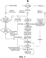
- FIG. 7 diagrams the operation of the software associated with the system 10 of the present invention, identified by "IMS".
- the software acts in accordance with the measurements obtained from strain gauges 60, 62, 64, and/or 66. If any of the strain gauges shows a load on table greater than the yellow threshold, vertical lines 82, 84, 86 and 88 on FIG. 6 , the software will display and "overload" error and ask the user to reboot the motorization of table 16. In other words, table 16 must be rebooted before any motion of spars 12, 14, 18, and 20 is permitted. If after reboot, table 16 still shows a load greater than the yellow limits indicated by vertical lines 82, 84, 86, and 88 of FIG.
- an overload message will be displayed in a particular electronic component by the software. Such error message will persist until acknowledged by the user after such acknowledgment, the display component will return to its home screen and the table will be allowed to move.
- the hand pendant depicted in United States Patent 8,584,281 would suffice in this regard.
- any of the signals from strain gauges 62, 64, 66, and/or 68 indicate that a voltage value is greater than any of the red threshold lines of demarcation, 74, 76, 78, and/or 80, the power will be cut to the motor mechanism 26 of table 16., an error message will be displayed on an electronics components screen, and the error message will persist until the user reboots table 16 or the offending force is removed from table 16.
- the software provides means to detect the state where any of the strain gauges, 60, 62, 64, and/or 66 are not connected to system 10. Again, such error message will be displayed.
- a momentary switch may be provided to override the disabling effects of the software on the motor mechanism of table 16 for the purposes of servicing table 16.
- FIGS. 8A and 8B detail the circuitry of a controller involved with the operation of system 10 of the present invention.
- the strain gauges 60, 62, 64, and 66 inputs comprise sensors that are fed into the circuit of FIG. 8A .
- P3 shows such inputs where the numeral 1 represents the excitation voltage (Vexcite), numeral 2 represents the tension/compression signal 100, numeral 3 represents the moment signal 102, and numeral 4 denotes a ground.
- C4 serves as a filter for Vexcite, the power supply.
- R8 and C3 comprise a low pass filter.
- R41 is a pull-down resistor for signal 100.
- R2, R3, R4, R12, and R34 are voltage dividers for U2A.
- R10, R13, R14, R19, and R28 serve the same purpose for U2C. Fixing the voltage value for U2A and U2C would obviate the need for such voltage dividers.
- Amps U2A, U2B, and U2C represent the high point voltage, the buffering voltage, and the low point voltage, respectively.
- U2A and U2C serve as trip points for the input from strain gauges 60, 62, 64, and 66.
- Comparators U3A and U3B represents the high and low limits for operation of the motorized mechanism 26 of surgery table 16. In other words, the U2B analog voltage signal SG1 is compared to the outputs of U2A and U2C at U3A and U3B.
- U3A receives a plus-side signal from U2A and a minus-side signal SG1 from U2B.
- U3B receives a plus-side signal SG1 from U2B and a minus-side signal from U2C.
- D1 and D3 will provide visual alerts when the high or low Ref. signals, RefHi or RefLo, are exceeded by SG1, respectively.
- D2 and D4 are wired "or" gates that trigger the U5 buffer to relay U4.
- U4 is a power supply relay linked to motor relay P92, that intercepts power to motor 26.
- SW-PB switch S1 is the manual override switch to reactivate motor 26.
- the components of the circuitry of FIGS. 8A and 8B with respect to the tension/compression signal 100 also describes the components associated with the SG2 signal emanating from U2D, namely the moment signal 102 from table 16.
Landscapes
- Health & Medical Sciences (AREA)
- Engineering & Computer Science (AREA)
- Biomedical Technology (AREA)
- Life Sciences & Earth Sciences (AREA)
- Animal Behavior & Ethology (AREA)
- General Health & Medical Sciences (AREA)
- Public Health (AREA)
- Veterinary Medicine (AREA)
- Physics & Mathematics (AREA)
- General Physics & Mathematics (AREA)
- Accommodation For Nursing Or Treatment Tables (AREA)
Description
- The present invention relates to a novel and useful surgery table load monitoring system.
- Surgery tables are often constructed with moveable elements to allow orientation of a patient on the surgery table platform in order to allow a surgeon to perform medical procedures. For example, reference is made to United States Patent
8,584,281 which depicts a surgery table having coordinated motion and a platform that is hinged. - In the past, various movements of a motorized surgery table have been monitored by the operator. Unfortunately, recognition of abnormal movements of a motorized surgical table by personal may be overlooked or be untimely, resulting in injury to a patient.
-
Document DE 10 2006 008505 discloses a patient support table (1) has at least one sensor (7) on the table top (2) for determining the force for table top movement which is exerted on the table top by a user. The sensor communicates with the control unit (4) of the motor, which controls the motor in dependence upon the sensor signal with regard to a predetermined reference force value in such a way that the reference force value is not exceeded during movement of the table. -
WO2008022642 discloses a lifting column comprising two or more telescopically arranged column elements, where each column element comprises at least two column sub-elements arranged symmetrically on either side of a first vertical plane, one set of sub-column elements closer to the plane than the other set of sub-elements, where the outer sub-elements are slidingly connected to adjacent inner sub-elements by means of guiding sledges, and further where each column sub-element comprises at least two pulley wheels, one up- per and one lower, and further where one first continuous flexible member runs from an upper pulley wheel of a first sub-element to a lower pulley wheel on an adjacent sub-element, so that the first flexible member runs on the upper or lower pulley wheels of the innermost sub-elements on either side of the vertical plane, and that the flexible member is shortened or lengthened by rolling at least one end of the flexible member around a drive wheel on a rotatable axle of an actuating motor. The invention also relates to a patient support table, comprising a patient support surface, a lifting column and a foundation structure for fastening said patient support ta ble to a floor surface. - In accordance with the present invention, as defined by the appended claims, a novel and useful surgery table load monitoring system is herein provided.
- The monitoring system of the present invention is intended to prevent a motorized surgery table from being overloaded to the point of failure.
- The system of the present invention utilizes a base member having detectors, which may be in the form of strain gauges that are mounted to a portion of the surgery table. For example, the base member may be connected to the head plate of a motorized surgery table such as that found in United States Patent
8,584,281 . Each strain gauge may be in the form of a strain-bridge that is sensitive to tension/compression, and moment loading to the structure of the surgery table. Such structural components of the motorized surgery table are typically in the form of spars or the like found near the platform supporting the patient. The analog output from the strain-gage bridges feed a hardware-only comparator that may be integrated into an existing processor on the surgery table, such as a processor that monitors the loads imposed on the surgery table patient support components. In the present invention, if the load as measured by the strain-gages exceeds a preset threshold, the hardware-only circuit will remove power from motors used to position the table. In this manner, additional stress on the table is prevented. The power may be restored to the surgery table motors only when the load on the table is reduced by some means. This usually occurs when the strain-gage output falls below a preset threshold. - As heretofore discussed, the analog output from the strain-gage bridges may be fed to an existing processor or controller associated with the motorized table such as one found in
U.S. Patent 8,584,281 . The processor will monitor and track the load on the table component, such as the head plate, to warn the user when the table is approaching a danger threshold. At this juncture, the hardware-only circuit activates and the user of the table will be prompted to reboot the table. - It may be apparent that a novel and useful surgery table load monitoring system has hereinabove described.
- It is therefore an object of the present invention to provide a surgery table load monitoring system that prevents injury to the patient should the surgery table be weight overloaded in some manner.
- Another object of the present invention is to provide a surgery table load monitoring system that limits its risks associated with a motorized surgery table that is not operating properly.
- Another object of the present invention is to provide a surgery table load monitoring system that prevents damage to a surgery table and injury to a patient, when a software program associated with a control fails during use of the surgery table.
- A further object of the present invention is to provide a surgery table load monitoring system that serves as a shut-off device due to electronic or software failures associated with the manipulating and positioning a surgery table.
- Another object of the present invention is to provide a surgery table load monitoring system that includes detectors or gages that monitor tension, compression, and moment loads on spars that are associated with the support of a patient on a surgical table.
- A further object of the present invention is to provide a system for monitoring loads on a surgery table in order to interrupt power to the motors manipulating such surgery table according to a system of zone limits or thresholds for particular load forces.
- Another object of the present invention is to provide a surgery table load monitoring system which is easily integrated into a known processor associated with a motorized surgery table.
- The invention possesses other objects and advantages especially as concerns particular characteristics and features thereof which will become apparent as the specification continues.
-
-
FIG. 1 is a prospective view of a portion of a motorized surgery table having a pair of spars connectable to the base member of the present invention. -
FIG. 2 is a partial side elevational view of a motorized surgery table utilizing the present invention in which the forces on a spar connected to the base member of the present invention are delineated. -
FIG. 3A & 3B are schematic views of the base member of the present invention showing various strains thereupon due to forces on the spar or other supports for the patient of a motorized surgery table. -
FIG. 4 is a front elevational view of the base member of the present invention. -
FIG. 5 is a block diagram showing overall loading on the surgery table patient support as well as the enabling and disabling of the motor power. -
FIG. 6 is a diagram depicting the zone limits established for the various forces loaded/on a motorized surgery table. -
FIG. 7 is a diagram indicting the operation of the software associated with the system of the present invention. -
FIGS. 8A and8B are contiguous circuit diagrams with overlapping elements showing the operation of the signals generated by the detectors mounted on a base member of a motorized surgery table. - For a better understanding of the invention reference is made to the following detailed description of the preferred embodiments of the invention which should be taken in conjunction with the above described drawings.
- Various aspects of the present invention will evolve from the following detailed description of the preferred embodiments thereof which should be referenced to the prior described drawings.
- The surgery table load monitoring system is indicated by
reference character 10 to show the physical components of the same as a whole. With reference toFIG. 1 , it may be seen that spars 12 and 14 are connected tospars hinges Motor mechanism 26, shown partially inFIG. 1 , operates the movement ofspars 8,584,281 heretofore noted. A patient support (not shown) may also be employed to lie againstspars - Surgery table 16 includes a
head plate 28. Abase member 30 ofsystem 10 lies against and is connected tohead plate 28.Spar 12 and hinge linkedspar 18 is shown as being linked tobase member 30.Spar 14 and hinged connectedspar 20 are indicated onFIG. 1 as being linked tobase member 30 bydirectional arrow 32. -
FIG. 2 , illustratingspar 14 as being connected tobase member 30, represents the particular loads that may be imposed uponspars spars force arrows - Turning to
FIGS 3A & 3B , it may be observed that schematic representations ofbase member 30 are shown.FIG. 3A represents a top plan view whileFIG 3B represents a right side view ofbase member 30. Endportions FIG. 3A , in dashed line format, indicate the exaggerated deformation ofbase member 30 under tension,directional arrows End portions base member 30, shown in dashed format, represent the exaggerated movement ofbase member 30 under compression,directional arrows FIG. 3B represents the moment force,directional arrow 56, exerted onbase member 30 and the exaggerated deformation ofbase member 30 is shown by dashed-line figure 58. It should be understood, that the movements depicted inFIGS. 3A and 3B originate with forces exerted onspars -
FIG. 4 illustratesbase member 30 that lies againsthead plate 28. It should be noted thatbase member 30 may be located in other areas of surgery table 16 such as a foot plate, a support structure, and the like, to obtain a reading of the forces onspars Base member 30 includes asurface 60 supporting moment strain gauges 60 and 62, as well as tension/compression strain gauges 64 and 66.Arrows strain gauges 64 and 66, respectively.Oval portion 72 denotes placement of electrical and electronic components such as, amplifiers and the like which are linked to strain gauges, 60, 62, 64, and 68, and which will be further discussed hereinafter. -
FIG. 5 shows the overall operation ofsystem 10 in which the power tomotor mechanism 26 of table 16,FIG. 1 , is either enabled or disabled according to the measurements of the loads onspars strain gauges spars strain gauges head plate 28,FIG. 1 , and warns the user of table 16 when it is approaching a threshold at which power tomotor 26 is disabled. The user will then be prompted to adjust such load on table 16 and reboot the table when it is possible to do so. -
FIG. 6 represents the zone limits of tension, compression, upward moment and downward moment forces onspars FIG. 6 , zones are indicated by the colors white, green, yellow, and red. Values in the green or white zones are considered safe, based on the table operating normally where there is no fault condition or lack of coordinated motion by the motorized power, partially shown inFIG. 1 asmotor mechanism 26.FIG. 6 also indicates typical measured voltages related to the quantity of tension, compression, upward moment and/or downward moment forces, shown in pounds or, in the case of moment forces, in inch-pounds. Values found in the yellow zones measured bystrain gauges motor 26 will be disabled according toFIG. 5 . Vertical lines of demarcation, 74, 76, 78 or 80, mark the boundaries between yellow zones and red zones, the latter zone triggering a disabling of themotor 26 power to table 16. The measurements obtained fromstrain gauges thresholds strain gauges system 10 of the present invention, which will be discussed hereinafter. -
FIG. 7 diagrams the operation of the software associated with thesystem 10 of the present invention, identified by "IMS". In essence, the software acts in accordance with the measurements obtained fromstrain gauges vertical lines FIG. 6 , the software will display and "overload" error and ask the user to reboot the motorization of table 16. In other words, table 16 must be rebooted before any motion ofspars vertical lines FIG. 6 , an overload message will be displayed in a particular electronic component by the software. Such error message will persist until acknowledged by the user after such acknowledgment, the display component will return to its home screen and the table will be allowed to move. For example, the hand pendant depicted in United States Patent8,584,281 would suffice in this regard. - Should any of the signals from
strain gauges motor mechanism 26 of table 16., an error message will be displayed on an electronics components screen, and the error message will persist until the user reboots table 16 or the offending force is removed from table 16. In addition, the software provides means to detect the state where any of the strain gauges, 60, 62, 64, and/or 66 are not connected tosystem 10. Again, such error message will be displayed. A momentary switch may be provided to override the disabling effects of the software on the motor mechanism of table 16 for the purposes of servicing table 16. -
FIGS. 8A and8B detail the circuitry of a controller involved with the operation ofsystem 10 of the present invention. The strain gauges 60, 62, 64, and 66 inputs comprise sensors that are fed into the circuit ofFIG. 8A . P3 shows such inputs where thenumeral 1 represents the excitation voltage (Vexcite),numeral 2 represents the tension/compression signal 100, numeral 3 represents the moment signal 102, and numeral 4 denotes a ground. C4 serves as a filter for Vexcite, the power supply. Following the path of tension/compression signal 100, R8 and C3 comprise a low pass filter. R41 is a pull-down resistor forsignal 100. R2, R3, R4, R12, and R34 are voltage dividers for U2A. R10, R13, R14, R19, and R28 serve the same purpose for U2C. Fixing the voltage value for U2A and U2C would obviate the need for such voltage dividers. Amps U2A, U2B, and U2C represent the high point voltage, the buffering voltage, and the low point voltage, respectively. Thus, U2A and U2C serve as trip points for the input fromstrain gauges motorized mechanism 26 of surgery table 16. In other words, the U2B analog voltage signal SG1 is compared to the outputs of U2A and U2C at U3A and U3B. U3A receives a plus-side signal from U2A and a minus-side signal SG1 from U2B. Likewise, U3B receives a plus-side signal SG1 from U2B and a minus-side signal from U2C. D1 and D3 will provide visual alerts when the high or low Ref. signals, RefHi or RefLo, are exceeded by SG1, respectively. D2 and D4 are wired "or" gates that trigger the U5 buffer to relay U4. U4 is a power supply relay linked to motor relay P92, that intercepts power tomotor 26. SW-PB switch S1 is the manual override switch to reactivatemotor 26. The components of the circuitry ofFIGS. 8A and8B with respect to the tension/compression signal 100, also describes the components associated with the SG2 signal emanating from U2D, namely the moment signal 102 from table 16. - While in the foregoing, embodiments of the present invention have been set forth in considerable detail for the purposes of making a complete disclosure of the invention, it may be apparent to those of skill in the art that numerous changes may be made in such detail without departing from the principles of the invention as defined by the appended claims.
Claims (6)
- A medical table structure comprising an apparatus for monitoring a load applied to said medical table structure (16), the medical table structure (16) including a head rest, a patient support and a motor mechanism (26) for positioning the patient support, the apparatus comprising:a base member (30), said base member being linked to the medical table structure (16) and the patient support, said base member (30) comprising a plate (28);at least one strain gauge (60, 62, 64, 66) connected to the medical table structure (16), said one strain gauge detecting a load imposed on the patient support and generating an output signal representing the quantity of said load;a controller, said controller receiving said output signal from said at least one strain gauge (60, 62, 64, 66) and determining the functioning of the motor mechanism (26) thereby;wherein said plate (28) is affixed to said head support.
- The medical table structure of claim 1 wherein the apparatus which additionally comprises another strain gauge (60, 62, 64, 66) connected to the medical table structure (16) for detecting a load imposed on the patient support, said one and another strain gauges (60, 62, 64, 66) detecting loads including tension, compression, and moment.
- The medical table structure of claim 1 in which the patient support structure(16) includes a spar (12, 14, 16, 18) and the spar is connected to said base member plate (28).
- The medical table structure of claim 1 in which said controller comprises a comparator receiving said output signal from said strain gauge and a reference signal, said comparator generating an output signal, and which further comprises a relay linked to said motor mechanism (26), said relay disabling said motor mechanism (28) when said strain gauge output signal exceeds said reference signal.
- The medical table structure of claim 3 wherein the apparatus additionally comprises another strain gauge (64, 66) connected to the medical table structure for detecting a load imposed on the patient support, said one and another strain gauges (60, 62, 64, 66) detecting loads including tension, compression, and moment.
- The medical table structure of claim 4 in which the patient support structure includes a spar and the spar is connected to said base member plate.
Applications Claiming Priority (1)
| Application Number | Priority Date | Filing Date | Title |
|---|---|---|---|
| US15/066,907 US9958313B2 (en) | 2016-03-10 | 2016-03-10 | Surgery table load monitoring system |
Publications (2)
| Publication Number | Publication Date |
|---|---|
| EP3216436A1 EP3216436A1 (en) | 2017-09-13 |
| EP3216436B1 true EP3216436B1 (en) | 2018-12-05 |
Family
ID=58266972
Family Applications (1)
| Application Number | Title | Priority Date | Filing Date |
|---|---|---|---|
| EP17160371.5A Active EP3216436B1 (en) | 2016-03-10 | 2017-03-10 | Surgery table load monitoring system |
Country Status (8)
| Country | Link |
|---|---|
| US (1) | US9958313B2 (en) |
| EP (1) | EP3216436B1 (en) |
| JP (1) | JP6600657B2 (en) |
| KR (1) | KR101955085B1 (en) |
| CN (1) | CN107174464B (en) |
| AU (1) | AU2017201551B2 (en) |
| CA (1) | CA2959398C (en) |
| TR (1) | TR201902462T4 (en) |
Family Cites Families (10)
| Publication number | Priority date | Publication date | Assignee | Title |
|---|---|---|---|---|
| US4869266A (en) * | 1985-12-31 | 1989-09-26 | Stonecrest Systems, Inc. | Patient monitoring unit for surgical use |
| JP2515132Y2 (en) * | 1991-10-17 | 1996-10-30 | 株式会社長田中央研究所 | Dental care unit |
| JPH10165462A (en) * | 1996-12-05 | 1998-06-23 | Olympus Optical Co Ltd | Medical bed device |
| EP1858469A4 (en) * | 2005-02-23 | 2012-05-16 | Stryker Canadian Man Inc | Hospital patient support |
| EP1931298B1 (en) * | 2005-08-10 | 2017-05-31 | Mizuho Orthopedic Systems, Inc. | Medical table having controlled movement |
| DE102006008505A1 (en) * | 2006-02-23 | 2007-08-30 | Siemens Ag | Patient support table has at least one sensor on table top for determining force for table top movement which is exerted on table top by user, wherein sensor communicates with control unit of motor |
| EP2059208B1 (en) * | 2006-08-24 | 2010-07-14 | NRT-Nordisk Røntgen Teknik A/S | Lifting column with patient support table |
| US8584281B2 (en) * | 2011-04-07 | 2013-11-19 | Mizuho Orthopedic Systems, Inc | Surgery table having coordinated motion |
| DE102011078567B4 (en) * | 2011-07-04 | 2014-08-28 | Siemens Aktiengesellschaft | Patient storage device for a medical imaging device, and a medical imaging device with the patient support device |
| WO2014151642A1 (en) * | 2013-03-15 | 2014-09-25 | Intuitive Surgical Operations, Inc. | Surgical patient side cart with steering interface |
-
2016
- 2016-03-10 US US15/066,907 patent/US9958313B2/en active Active
-
2017
- 2017-02-28 CA CA2959398A patent/CA2959398C/en active Active
- 2017-03-06 JP JP2017041326A patent/JP6600657B2/en active Active
- 2017-03-07 AU AU2017201551A patent/AU2017201551B2/en active Active
- 2017-03-08 CN CN201710135664.2A patent/CN107174464B/en active Active
- 2017-03-09 KR KR1020170030011A patent/KR101955085B1/en active Active
- 2017-03-10 EP EP17160371.5A patent/EP3216436B1/en active Active
- 2017-03-10 TR TR2019/02462T patent/TR201902462T4/en unknown
Non-Patent Citations (1)
| Title |
|---|
| None * |
Also Published As
| Publication number | Publication date |
|---|---|
| US20170261363A1 (en) | 2017-09-14 |
| CN107174464A (en) | 2017-09-19 |
| KR20170106228A (en) | 2017-09-20 |
| CA2959398C (en) | 2020-06-30 |
| CN107174464B (en) | 2019-05-28 |
| KR101955085B1 (en) | 2019-05-17 |
| CA2959398A1 (en) | 2017-09-10 |
| AU2017201551B2 (en) | 2018-06-07 |
| JP6600657B2 (en) | 2019-10-30 |
| TR201902462T4 (en) | 2019-03-21 |
| US9958313B2 (en) | 2018-05-01 |
| JP2017159040A (en) | 2017-09-14 |
| EP3216436A1 (en) | 2017-09-13 |
| AU2017201551A1 (en) | 2017-09-28 |
Similar Documents
| Publication | Publication Date | Title |
|---|---|---|
| US8858409B2 (en) | Patient support apparatuses with exercise functionalities | |
| US6439341B1 (en) | Apparatus for monitoring loading of a lift | |
| US7493987B2 (en) | Platform load sensing for vertical lifts | |
| CN108455489A (en) | Improvement stabilizer for self-propelled Work machine | |
| US20170014256A1 (en) | Method and Apparatus for Applying and Controlling Surgical Traction | |
| US7690056B2 (en) | Stretcher supporter for a storable patient lift and transfer device and method for doing the same | |
| CA2976453A1 (en) | Operator protection apparatus with an over-center linkage | |
| US8931124B2 (en) | Surgical table having overload detection means | |
| CA2959398C (en) | Surgery table load monitoring system | |
| JP5692125B2 (en) | Walking assistance system and control method thereof | |
| US20120128448A1 (en) | Lifting device with distributed-sensing scale | |
| US20250383253A1 (en) | Safety system for detecting a collision of a medical table | |
| CN220917556U (en) | Digital electronic tractor | |
| AU2015224374B2 (en) | A Surgical Table having Overload Detection Means | |
| KR20110137150A (en) | Safety mechanism of lower extremity rehabilitation exercise machine | |
| US12465545B2 (en) | Walking training system, control method thereof, and control program | |
| CN207166288U (en) | A kind of skiing simulating machine and its lift control system | |
| CN121154400A (en) | Rehabilitation protector with fall protection function |
Legal Events
| Date | Code | Title | Description |
|---|---|---|---|
| PUAI | Public reference made under article 153(3) epc to a published international application that has entered the european phase |
Free format text: ORIGINAL CODE: 0009012 |
|
| STAA | Information on the status of an ep patent application or granted ep patent |
Free format text: STATUS: THE APPLICATION HAS BEEN PUBLISHED |
|
| AK | Designated contracting states |
Kind code of ref document: A1 Designated state(s): AL AT BE BG CH CY CZ DE DK EE ES FI FR GB GR HR HU IE IS IT LI LT LU LV MC MK MT NL NO PL PT RO RS SE SI SK SM TR |
|
| AX | Request for extension of the european patent |
Extension state: BA ME |
|
| STAA | Information on the status of an ep patent application or granted ep patent |
Free format text: STATUS: REQUEST FOR EXAMINATION WAS MADE |
|
| 17P | Request for examination filed |
Effective date: 20180312 |
|
| RBV | Designated contracting states (corrected) |
Designated state(s): AL AT BE BG CH CY CZ DE DK EE ES FI FR GB GR HR HU IE IS IT LI LT LU LV MC MK MT NL NO PL PT RO RS SE SI SK SM TR |
|
| GRAP | Despatch of communication of intention to grant a patent |
Free format text: ORIGINAL CODE: EPIDOSNIGR1 |
|
| STAA | Information on the status of an ep patent application or granted ep patent |
Free format text: STATUS: GRANT OF PATENT IS INTENDED |
|
| INTG | Intention to grant announced |
Effective date: 20180621 |
|
| GRAS | Grant fee paid |
Free format text: ORIGINAL CODE: EPIDOSNIGR3 |
|
| GRAA | (expected) grant |
Free format text: ORIGINAL CODE: 0009210 |
|
| STAA | Information on the status of an ep patent application or granted ep patent |
Free format text: STATUS: THE PATENT HAS BEEN GRANTED |
|
| AK | Designated contracting states |
Kind code of ref document: B1 Designated state(s): AL AT BE BG CH CY CZ DE DK EE ES FI FR GB GR HR HU IE IS IT LI LT LU LV MC MK MT NL NO PL PT RO RS SE SI SK SM TR |
|
| REG | Reference to a national code |
Ref country code: GB Ref legal event code: FG4D |
|
| REG | Reference to a national code |
Ref country code: CH Ref legal event code: EP |
|
| REG | Reference to a national code |
Ref country code: AT Ref legal event code: REF Ref document number: 1072156 Country of ref document: AT Kind code of ref document: T Effective date: 20181215 |
|
| REG | Reference to a national code |
Ref country code: IE Ref legal event code: FG4D |
|
| REG | Reference to a national code |
Ref country code: DE Ref legal event code: R096 Ref document number: 602017001144 Country of ref document: DE |
|
| REG | Reference to a national code |
Ref country code: SE Ref legal event code: TRGR |
|
| REG | Reference to a national code |
Ref country code: NL Ref legal event code: FP |
|
| REG | Reference to a national code |
Ref country code: AT Ref legal event code: MK05 Ref document number: 1072156 Country of ref document: AT Kind code of ref document: T Effective date: 20181205 |
|
| REG | Reference to a national code |
Ref country code: LT Ref legal event code: MG4D |
|
| PG25 | Lapsed in a contracting state [announced via postgrant information from national office to epo] |
Ref country code: NO Free format text: LAPSE BECAUSE OF FAILURE TO SUBMIT A TRANSLATION OF THE DESCRIPTION OR TO PAY THE FEE WITHIN THE PRESCRIBED TIME-LIMIT Effective date: 20190305 Ref country code: LT Free format text: LAPSE BECAUSE OF FAILURE TO SUBMIT A TRANSLATION OF THE DESCRIPTION OR TO PAY THE FEE WITHIN THE PRESCRIBED TIME-LIMIT Effective date: 20181205 Ref country code: HR Free format text: LAPSE BECAUSE OF FAILURE TO SUBMIT A TRANSLATION OF THE DESCRIPTION OR TO PAY THE FEE WITHIN THE PRESCRIBED TIME-LIMIT Effective date: 20181205 Ref country code: BG Free format text: LAPSE BECAUSE OF FAILURE TO SUBMIT A TRANSLATION OF THE DESCRIPTION OR TO PAY THE FEE WITHIN THE PRESCRIBED TIME-LIMIT Effective date: 20190305 Ref country code: AT Free format text: LAPSE BECAUSE OF FAILURE TO SUBMIT A TRANSLATION OF THE DESCRIPTION OR TO PAY THE FEE WITHIN THE PRESCRIBED TIME-LIMIT Effective date: 20181205 Ref country code: FI Free format text: LAPSE BECAUSE OF FAILURE TO SUBMIT A TRANSLATION OF THE DESCRIPTION OR TO PAY THE FEE WITHIN THE PRESCRIBED TIME-LIMIT Effective date: 20181205 Ref country code: LV Free format text: LAPSE BECAUSE OF FAILURE TO SUBMIT A TRANSLATION OF THE DESCRIPTION OR TO PAY THE FEE WITHIN THE PRESCRIBED TIME-LIMIT Effective date: 20181205 |
|
| PG25 | Lapsed in a contracting state [announced via postgrant information from national office to epo] |
Ref country code: AL Free format text: LAPSE BECAUSE OF FAILURE TO SUBMIT A TRANSLATION OF THE DESCRIPTION OR TO PAY THE FEE WITHIN THE PRESCRIBED TIME-LIMIT Effective date: 20181205 Ref country code: RS Free format text: LAPSE BECAUSE OF FAILURE TO SUBMIT A TRANSLATION OF THE DESCRIPTION OR TO PAY THE FEE WITHIN THE PRESCRIBED TIME-LIMIT Effective date: 20181205 Ref country code: GR Free format text: LAPSE BECAUSE OF FAILURE TO SUBMIT A TRANSLATION OF THE DESCRIPTION OR TO PAY THE FEE WITHIN THE PRESCRIBED TIME-LIMIT Effective date: 20190306 |
|
| PG25 | Lapsed in a contracting state [announced via postgrant information from national office to epo] |
Ref country code: PL Free format text: LAPSE BECAUSE OF FAILURE TO SUBMIT A TRANSLATION OF THE DESCRIPTION OR TO PAY THE FEE WITHIN THE PRESCRIBED TIME-LIMIT Effective date: 20181205 Ref country code: PT Free format text: LAPSE BECAUSE OF FAILURE TO SUBMIT A TRANSLATION OF THE DESCRIPTION OR TO PAY THE FEE WITHIN THE PRESCRIBED TIME-LIMIT Effective date: 20190405 Ref country code: ES Free format text: LAPSE BECAUSE OF FAILURE TO SUBMIT A TRANSLATION OF THE DESCRIPTION OR TO PAY THE FEE WITHIN THE PRESCRIBED TIME-LIMIT Effective date: 20181205 Ref country code: IT Free format text: LAPSE BECAUSE OF FAILURE TO SUBMIT A TRANSLATION OF THE DESCRIPTION OR TO PAY THE FEE WITHIN THE PRESCRIBED TIME-LIMIT Effective date: 20181205 Ref country code: CZ Free format text: LAPSE BECAUSE OF FAILURE TO SUBMIT A TRANSLATION OF THE DESCRIPTION OR TO PAY THE FEE WITHIN THE PRESCRIBED TIME-LIMIT Effective date: 20181205 |
|
| PG25 | Lapsed in a contracting state [announced via postgrant information from national office to epo] |
Ref country code: RO Free format text: LAPSE BECAUSE OF FAILURE TO SUBMIT A TRANSLATION OF THE DESCRIPTION OR TO PAY THE FEE WITHIN THE PRESCRIBED TIME-LIMIT Effective date: 20181205 Ref country code: IS Free format text: LAPSE BECAUSE OF FAILURE TO SUBMIT A TRANSLATION OF THE DESCRIPTION OR TO PAY THE FEE WITHIN THE PRESCRIBED TIME-LIMIT Effective date: 20190405 Ref country code: EE Free format text: LAPSE BECAUSE OF FAILURE TO SUBMIT A TRANSLATION OF THE DESCRIPTION OR TO PAY THE FEE WITHIN THE PRESCRIBED TIME-LIMIT Effective date: 20181205 Ref country code: SM Free format text: LAPSE BECAUSE OF FAILURE TO SUBMIT A TRANSLATION OF THE DESCRIPTION OR TO PAY THE FEE WITHIN THE PRESCRIBED TIME-LIMIT Effective date: 20181205 Ref country code: SK Free format text: LAPSE BECAUSE OF FAILURE TO SUBMIT A TRANSLATION OF THE DESCRIPTION OR TO PAY THE FEE WITHIN THE PRESCRIBED TIME-LIMIT Effective date: 20181205 |
|
| REG | Reference to a national code |
Ref country code: DE Ref legal event code: R097 Ref document number: 602017001144 Country of ref document: DE |
|
| PLBE | No opposition filed within time limit |
Free format text: ORIGINAL CODE: 0009261 |
|
| STAA | Information on the status of an ep patent application or granted ep patent |
Free format text: STATUS: NO OPPOSITION FILED WITHIN TIME LIMIT |
|
| PG25 | Lapsed in a contracting state [announced via postgrant information from national office to epo] |
Ref country code: MC Free format text: LAPSE BECAUSE OF FAILURE TO SUBMIT A TRANSLATION OF THE DESCRIPTION OR TO PAY THE FEE WITHIN THE PRESCRIBED TIME-LIMIT Effective date: 20181205 Ref country code: DK Free format text: LAPSE BECAUSE OF FAILURE TO SUBMIT A TRANSLATION OF THE DESCRIPTION OR TO PAY THE FEE WITHIN THE PRESCRIBED TIME-LIMIT Effective date: 20181205 Ref country code: SI Free format text: LAPSE BECAUSE OF FAILURE TO SUBMIT A TRANSLATION OF THE DESCRIPTION OR TO PAY THE FEE WITHIN THE PRESCRIBED TIME-LIMIT Effective date: 20181205 |
|
| 26N | No opposition filed |
Effective date: 20190906 |
|
| PG25 | Lapsed in a contracting state [announced via postgrant information from national office to epo] |
Ref country code: LU Free format text: LAPSE BECAUSE OF NON-PAYMENT OF DUE FEES Effective date: 20190310 |
|
| PG25 | Lapsed in a contracting state [announced via postgrant information from national office to epo] |
Ref country code: IE Free format text: LAPSE BECAUSE OF NON-PAYMENT OF DUE FEES Effective date: 20190310 |
|
| PG25 | Lapsed in a contracting state [announced via postgrant information from national office to epo] |
Ref country code: MT Free format text: LAPSE BECAUSE OF NON-PAYMENT OF DUE FEES Effective date: 20190310 |
|
| REG | Reference to a national code |
Ref country code: CH Ref legal event code: PL |
|
| PG25 | Lapsed in a contracting state [announced via postgrant information from national office to epo] |
Ref country code: LI Free format text: LAPSE BECAUSE OF NON-PAYMENT OF DUE FEES Effective date: 20200331 Ref country code: CH Free format text: LAPSE BECAUSE OF NON-PAYMENT OF DUE FEES Effective date: 20200331 |
|
| PG25 | Lapsed in a contracting state [announced via postgrant information from national office to epo] |
Ref country code: CY Free format text: LAPSE BECAUSE OF FAILURE TO SUBMIT A TRANSLATION OF THE DESCRIPTION OR TO PAY THE FEE WITHIN THE PRESCRIBED TIME-LIMIT Effective date: 20181205 |
|
| PG25 | Lapsed in a contracting state [announced via postgrant information from national office to epo] |
Ref country code: HU Free format text: LAPSE BECAUSE OF FAILURE TO SUBMIT A TRANSLATION OF THE DESCRIPTION OR TO PAY THE FEE WITHIN THE PRESCRIBED TIME-LIMIT; INVALID AB INITIO Effective date: 20170310 |
|
| PG25 | Lapsed in a contracting state [announced via postgrant information from national office to epo] |
Ref country code: MK Free format text: LAPSE BECAUSE OF FAILURE TO SUBMIT A TRANSLATION OF THE DESCRIPTION OR TO PAY THE FEE WITHIN THE PRESCRIBED TIME-LIMIT Effective date: 20181205 |
|
| PGFP | Annual fee paid to national office [announced via postgrant information from national office to epo] |
Ref country code: FR Payment date: 20251231 Year of fee payment: 10 |
|
| PGFP | Annual fee paid to national office [announced via postgrant information from national office to epo] |
Ref country code: NL Payment date: 20260106 Year of fee payment: 10 |
|
| PGFP | Annual fee paid to national office [announced via postgrant information from national office to epo] |
Ref country code: SE Payment date: 20260105 Year of fee payment: 10 |
|
| PGFP | Annual fee paid to national office [announced via postgrant information from national office to epo] |
Ref country code: GB Payment date: 20260106 Year of fee payment: 10 |
|
| PGFP | Annual fee paid to national office [announced via postgrant information from national office to epo] |
Ref country code: DE Payment date: 20260102 Year of fee payment: 10 |
|
| PGFP | Annual fee paid to national office [announced via postgrant information from national office to epo] |
Ref country code: BE Payment date: 20260105 Year of fee payment: 10 |
|
| PGFP | Annual fee paid to national office [announced via postgrant information from national office to epo] |
Ref country code: TR Payment date: 20260306 Year of fee payment: 10 |