EP3216420A1 - Blank for producing a dental element - Google Patents
Blank for producing a dental element Download PDFInfo
- Publication number
- EP3216420A1 EP3216420A1 EP17165754.7A EP17165754A EP3216420A1 EP 3216420 A1 EP3216420 A1 EP 3216420A1 EP 17165754 A EP17165754 A EP 17165754A EP 3216420 A1 EP3216420 A1 EP 3216420A1
- Authority
- EP
- European Patent Office
- Prior art keywords
- blanks
- clamping
- blank
- holding
- clamped
- Prior art date
- Legal status (The legal status is an assumption and is not a legal conclusion. Google has not performed a legal analysis and makes no representation as to the accuracy of the status listed.)
- Granted
Links
Images


Classifications
-
- A—HUMAN NECESSITIES
- A61—MEDICAL OR VETERINARY SCIENCE; HYGIENE
- A61C—DENTISTRY; APPARATUS OR METHODS FOR ORAL OR DENTAL HYGIENE
- A61C13/00—Dental prostheses; Making same
- A61C13/0003—Making bridge-work, inlays, implants or the like
- A61C13/0022—Blanks or green, unfinished dental restoration parts
-
- A—HUMAN NECESSITIES
- A61—MEDICAL OR VETERINARY SCIENCE; HYGIENE
- A61C—DENTISTRY; APPARATUS OR METHODS FOR ORAL OR DENTAL HYGIENE
- A61C13/00—Dental prostheses; Making same
-
- A—HUMAN NECESSITIES
- A61—MEDICAL OR VETERINARY SCIENCE; HYGIENE
- A61C—DENTISTRY; APPARATUS OR METHODS FOR ORAL OR DENTAL HYGIENE
- A61C5/00—Filling or capping teeth
- A61C5/70—Tooth crowns; Making thereof
- A61C5/77—Methods or devices for making crowns
-
- A—HUMAN NECESSITIES
- A61—MEDICAL OR VETERINARY SCIENCE; HYGIENE
- A61C—DENTISTRY; APPARATUS OR METHODS FOR ORAL OR DENTAL HYGIENE
- A61C13/00—Dental prostheses; Making same
- A61C13/12—Tools for fastening artificial teeth; Holders, clamps, or stands for artificial teeth
-
- B—PERFORMING OPERATIONS; TRANSPORTING
- B23—MACHINE TOOLS; METAL-WORKING NOT OTHERWISE PROVIDED FOR
- B23C—MILLING
- B23C2226/00—Materials of tools or workpieces not comprising a metal
- B23C2226/18—Ceramic
-
- B—PERFORMING OPERATIONS; TRANSPORTING
- B23—MACHINE TOOLS; METAL-WORKING NOT OTHERWISE PROVIDED FOR
- B23C—MILLING
- B23C2240/00—Details of connections of tools or workpieces
-
- Y—GENERAL TAGGING OF NEW TECHNOLOGICAL DEVELOPMENTS; GENERAL TAGGING OF CROSS-SECTIONAL TECHNOLOGIES SPANNING OVER SEVERAL SECTIONS OF THE IPC; TECHNICAL SUBJECTS COVERED BY FORMER USPC CROSS-REFERENCE ART COLLECTIONS [XRACs] AND DIGESTS
- Y10—TECHNICAL SUBJECTS COVERED BY FORMER USPC
- Y10T—TECHNICAL SUBJECTS COVERED BY FORMER US CLASSIFICATION
- Y10T409/00—Gear cutting, milling, or planing
- Y10T409/30—Milling
Definitions
- the invention relates to an arrangement with two blanks and a holding device for holding the two blanks, wherein the two blanks each have a first side formed as a front side and a rear side formed as a second side.
- Such a holding or clamping two blanks in a work table insert goes out of the DE 10 2010 061 116 A1 (equals to EP 2 462 894 A2 ) and in particular from Figure 9.1d.
- the two clamped blanks abut each other via a contact surface.
- the disadvantage is that these blanks are clamped over a large part of the front and rear sides in the work table insert. Thus, only a small protruding area is even editable.
- the object of the present invention is therefore to provide an arrangement which allows a simple and effective processing of two clamped blanks.
- both blanks have at least one auxiliary holding surface spaced from the rear side for holding the blank on a holding device, wherein the blank has a special holding thickness between the at least one auxiliary holding surface and the rear side and wherein the standard holding thickness is twice as large how the special holding thicknesses are.
- the holding device has at least one, preferably three, clamping device, wherein the blanks are clamped on their auxiliary holding surfaces of de clamping device on the holding device.
- each clamping device has a movable clamping part and a clamping surface, wherein in the clamped state, an auxiliary holding surface of a blank rests on the clamping surface and an auxiliary holding surface of the other blank rests on the clamping part.
- each clamping device has a movable clamping part and a clamping surface, wherein in the clamped state, an auxiliary holding surface of a blank rests on the clamping surface and an auxiliary holding surface of the other blank rests on the clamping part.
- the clamping device is suitable to clamp different thickness blanks.
- the clamping device can have mutually adjustable clamping parts and clamping surfaces.
- the movable clamping part and the clamping surface of the clamping device to each other have a substantially invariable, preferably the standard holding thickness corresponding distance.
- both a blank and two blank can be clamped in one and the same, simple clamping device.
- the blanks do not have to touch each other when clamped over their backs.
- the blanks in the clamped state over the mutually facing backs partially or completely abut each other.
- such an arrangement also has a processing device for processing the two blanks clamped in the holding device, wherein both blanks can be processed by the processing device via the substantially completely accessible front sides.
- the processing device and the holding device are relatively movable relative to each other, that both front sides are machined.
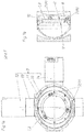
- Fig. 1a shows a holding device 3 for a blank 1, 2, as it has been manufactured for some time by the Applicant, offered and sold.
- a holding device has a substantially C-shaped carrier 12, on which the drive motors 13 and 14 are arranged.
- the outer retaining ring 11 is rotatably mounted.
- the inner retaining ring 10 is rotatably mounted on this outer retaining ring 11.
- the clamping device 6 In the inner retaining ring 10 is about the clamping device 6 and the clamping parts 7 of the blank 1, 2 clamped, wherein the clamping parts 7 in Fig. 1a in a passive position P are.
- Fig. 1a is indicated by the arrows on a cutting axis, the corresponding section in Fig. 1b is shown.
- the blank 1, 2 is inserted into the inner retaining ring 10 and rests on a clamping surface 8.
- the blank 1, 2 in this case has a first side (corresponding to a front side V) and a second side (corresponding to a rear side R).
- the clamping parts 7 are rotated about the clamping bolt 15 of the clamping device 6, whereby the clamping parts 7 reach a clamping position K.
- the blank 1, 2 is clamped over the main holding surfaces K 1 formed on the blank 1, 2 and the rear side (R) between the clamping surfaces 8 and the clamping parts 7 of the clamping device 6.
- the blank 1, 2 points between its back (R) and each Main holding surface K 1 a standard holding thickness D 1 on. In a preferred embodiment, this standard holding thickness D 1 is 10 mm.
- Fig. 2c the holding device 3 together with clamped blank 1, 2 is shown in a 3D view. There are also the axes of rotation for the two retaining rings 10 and 11 can be seen.
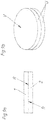
- Fig. 3a is in a side view of the substantially circular cylinder jacket-shaped peripheral surface U of a blank 1, 2 shown.
- this circular cylinder jacket-shaped peripheral surface U more recesses 4 are present. Through these recesses 4 are parallel to the front V and the back R main holding surfaces K 1 and auxiliary holding surfaces K 2 on the blank 1, 2 are formed.
- a part of the second side (corresponding to the rear side R) forms counter-holding surfaces G (see FIG Fig. 3g ).
- the main holding surfaces K 1 in the region of the recesses 4 and the rear side R are each spaced apart from each other by the standard holding thickness D 1 .
- the blank 1, 2 has the special holding thickness D 2 as a distance to the rear side R.
- the special holding thickness D 2 is smaller, preferably half as large as the standard holding thickness D 1 .
- the same components or surfaces are recognizable.
- the at least one positioning groove 16 can be seen, via which the blanks 1, 2 are clamped at a suitable location in the holding device 3. This also guarantees that when clamping two blanks 1, 2, the auxiliary holding surfaces K 2 of the two blanks 1, 2 correctly - that is axially opposite each other - to each other are positioned. Alternatively, it is also possible to realize a positioning via the position bores 19 formed in the rear side R.
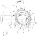
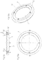
- Fig. 4a shows a holding device 3, which has an inner retaining ring 10, an outer retaining ring 11, a preferably C-shaped support 12 and two drive motors 13 and 14 for the two retaining rings 10 and 11.
- the inner retaining ring 10 are - as in Fig. 4b visible - the two blanks 1 and 2 used.
- the first blank 1 rests on the clamping surfaces 8 of the clamping device 6 via its auxiliary holding surfaces K 2 .
- the tensioning device 6 is formed by the clamping surfaces 8, the clamping parts 7 and the clamping bolt 15.
- the Fig. 4a and 4b are the clamping parts 7 still in the passive position P.
- the blanks 1, 2 according to the Fig. 6a to 6g be pre-processed or pre-milled.
- the blanks 1, 2 (blocks) are formed so that the remaining geometry of a denture modeled is. This has the advantage that it is no longer necessary to cut the complete block.
- the cutouts 17 thus no longer need to be incorporated by a device at the dental technician, but are already delivered with cutouts 17.
- the bit-shaped inner region of this blank 1, 2 is connected by connecting webs 18 with the outer region.
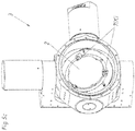
- Fig. 7a shows an assembly 5 with a holding device 3, two clamped in the holding device 3 blanks 1 and 2 and a processing device 9.
- This processing device 9 can, as in Fig. 7b shown to have a spindle.
- a milling cutter or the like may be arranged to machine the individual blanks 1 and 2 successively from the front side V, respectively.
- the inner retaining ring 10 can rotate at least by 180 °, preferably complete 360 °, about an axis. From this Fig. 7b is also clearly visible that in the clamped state, the entire front V of the blanks 1 and 2 is substantially completely accessible. As a result, unnecessary re-clamping is prevented and a complete working out of the dental elements E of two blanks 1 and 2 is feasible without intervening work by a dental technician would be necessary.
- the Fig. 8a and 8b show two blanks 1 and 2, wherein from the second blank 2 already only a schematically indicated dental element E is worked out. This dental element E is still connected via the webs 18 with the remaining area of the blank 2. In a later sequence, this dental element E is then removed from the second blank 2 by a dental technician or by special devices.
- Dental elements E can be, for example, crowns, bridges, or the like. Dental models are preferably produced from these blanks in order subsequently to perform teeth movement simulations. Also carrier models for dentures can be produced.
- the blanks 1 and 2 may, for example, zircon, metal, gypsum or plastic.
- the special holding thicknesses D 2 in the area of the auxiliary holding surfaces K 2 together give the standard holding thickness D 1 .
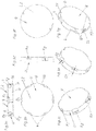
- Fig. 9a and 9b show two blanks 1 and 2, which abut each other over their respective rear side R.
- Such simple, cylindrical blanks 1 and 2 can be clamped in an arrangement according to the invention and processed over both substantially completely accessible front sides V.
- Fig. 11 a and 11 b show blanks 1 and 2, each with a continuous, peripheral gradation 21st
- Such gradation 21 is also in the blanks according to the Fig. 12a to 12c available.
- a tensioning device 6 In the Fig. 13a to 16c an alternative embodiment of a tensioning device 6 is shown. Thus, all these representations have in common that the tensioning device 6 has an annular, one-piece clamping part 7, a plurality of clamping bolts 15 in the form of screws and the (inner) retaining ring 10 formed clamping surfaces 8.
- Fig. 15c shows that the retaining ring 10 additionally has an intermediate piece 22 which forms the clamping surface 8.
- Fig. 16a to 16c are two blanks 1 and 2 clamped in such a holding device 3.
- a second, lower annular clamping part 7 is provided.
- a tensioning bolt 15 suitable internal thread may be formed in this lower clamping part 7.
- the lower clamping part 7 via two "coming from below” and from there screwed to the retaining ring 10 clamping bolt 15 with the retaining ring 10 is connectable.
- Fig. 16a is through the dashed lines indicated that more than two blanks 1 and 2 can be held in a holding device 3.
- two separate, spaced and smaller (in this case approximately semicircular) blanks 1 can be clamped in "one plane".
- the second blank 2 can be processed by the processing device 9 at least partially via its rear side R. This is also possible if previously a sufficient range was already released by processing the first blank 1, which allows access to the back R of the second blank 2.
Abstract
Anordnung (5) mit wenigstens zwei Rohlingen (1, 2) und einer Haltevorrichtung (3) zum Festspannen der beiden Rohlinge (1, 2), wobei die beiden Rohlinge (1, 2) jeweils eine als Vorderseite (V) ausgebildete erste Seite und jeweils eine als Rückseite (R) ausgebildete zweite Seite aufweisen, wobei in eingespanntem Zustand die beiden Rohlinge (1, 2) mit den Rückseiten (R) einander zugewandt sind und im Wesentlichen die kompletten Vorderseiten (V) der Rohlinge (1, 2) zugänglich sind.Arrangement (5) with at least two blanks (1, 2) and a holding device (3) for clamping the two blanks (1, 2), wherein the two blanks (1, 2) each formed as a front (V) first side and each having a trained as a rear side (R) second side, wherein in the clamped state, the two blanks (1, 2) with the rear sides (R) facing each other and substantially the complete front sides (V) of the blanks (1, 2) accessible are.
Description
Die Erfindung betrifft eine Anordnung mit zwei Rohlingen und einer Haltevorrichtung zum Festhalten der beiden Rohlinge, wobei die beiden Rohlinge jeweils eine als Vorderseite ausgebildete erste Seite und eine als Rückseite ausgebildete zweite Seite aufweisen.The invention relates to an arrangement with two blanks and a holding device for holding the two blanks, wherein the two blanks each have a first side formed as a front side and a rear side formed as a second side.
Ein derartiges Festhalten bzw. Einspannen von zwei Rohlingen in einem Werktischeinsatz (Haltevorrichtung) geht aus der
Die Aufgabe der vorliegenden Erfindung besteht daher darin, eine Anordnung zu schaffen, die eine einfache und effektive Bearbeitung von zwei eingespannten Rohlingen ermöglicht.The object of the present invention is therefore to provide an arrangement which allows a simple and effective processing of two clamped blanks.
Dies wird durch eine Anordnung mit den Merkmalen von Anspruch 1 gelöst. Demnach ist vorgesehen, dass in eingespanntem Zustand die beiden Rohlinge mit den Rückseiten einander zugewandt sind und im Wesentlichen die kompletten Vorderseiten der Rohlinge zugänglich sind. Dadurch ist es nicht mehr notwendig, die Rohlinge umzuspannen oder anders einzusetzen, um aus möglichst dem gesamten Rohling die gewünschten Dentalelemente herauszuarbeiten. "Im Wesentlichen die kompletten Vorderseiten" bedeutet dabei, dass (in einer Draufsicht gesehen) zumindest 80 %, vorzugsweise zumindest 90%, besonders bevorzugt zumindest 95%, der Vorderseiten in eingespanntem Zustand für eine Bearbeitungsvorrichtung frei zugänglich sind.This is achieved by an arrangement having the features of
Bei einer derartigen Anordnung kann das Festhalten der beiden Rohlinge an sich auf beliebige Art und Weise erfolgen, solange eben die beiden Vorderseiten möglichst komplett zugänglich sind. Bevorzugt ist aber vorgesehen, dass beide Rohlinge zumindest eine, von der Rückseite beabstandete Hilfshaltefläche zum Festhalten des Rohlings an einer Haltevorrichtung aufweist, wobei der Rohling zwischen der zumindest einen Hilfshaltefläche und der Rückseite eine Sonder-Haltedicke aufweist und wobei die Standard-Haltedicke doppelt so groß wie die Sonder-Haltedicken ist.In such an arrangement, the holding of the two blanks can be done in any way, as long as the two front sides are completely accessible. Preferably, however, it is provided that both blanks have at least one auxiliary holding surface spaced from the rear side for holding the blank on a holding device, wherein the blank has a special holding thickness between the at least one auxiliary holding surface and the rear side and wherein the standard holding thickness is twice as large how the special holding thicknesses are.
Für ein einfaches Festspannen der beiden Rohlinge ist bevorzugt vorgesehen, dass die Haltevorrichtung zumindest eine, vorzugsweise drei, Spannvorrichtung aufweist, wobei die Rohlinge über ihre Hilfshalteflächen von de Spannvorrichtung an der Haltevorrichtung festspannbar sind. Bei einem konkreten Ausführungsbeispiel ist dazu weiters vorgesehen, dass - bei mehreren Spannvorrichtungen - jede Spannvorrichtung ein bewegbares Spannteil und eine Spannfläche aufweist, wobei in eingespanntem Zustand eine Hilfshaltefläche des einen Rohlings an der Spannfläche aufliegt und eine Hilfshaltefläche des anderen Rohlings am Spannteil anliegt. Natürlich kann über dieselbe Spannvorrichtung auch ein einzelner Rohling über die Haupthaltefläche und die Rückseite eingespannt werden.For a simple clamping of the two blanks is preferably provided that the holding device has at least one, preferably three, clamping device, wherein the blanks are clamped on their auxiliary holding surfaces of de clamping device on the holding device. In a concrete embodiment, it is further provided that - with several clamping devices - each clamping device has a movable clamping part and a clamping surface, wherein in the clamped state, an auxiliary holding surface of a blank rests on the clamping surface and an auxiliary holding surface of the other blank rests on the clamping part. Of course, can be clamped on the same clamping device and a single blank on the main holding surface and the back.
Prinzipiell ist es möglich, dass die Spannvorrichtung geeignet ist, um unterschiedlich dicke Rohlinge einzuspannen. So kann die Spannvorrichtung zueinander variabel einstellbare Spannteile und Spannflächen aufweisen. Bevorzugt ist für eine einfache Bauweise allerdings vorgesehen, dass das bewegbare Spannteil und die Spannfläche der Spannvorrichtung zueinander einen im Wesentlichen unveränderlichen, vorzugsweise der Standard-Haltedicke entsprechenden, Abstand aufweisen. Somit können in ein und dieselbe, einfach gebaute Spannvorrichtung sowohl ein Rohling als auch zwei Rohling eingespannt werden.In principle, it is possible that the clamping device is suitable to clamp different thickness blanks. Thus, the clamping device can have mutually adjustable clamping parts and clamping surfaces. Preferably, however, it is provided for a simple design that the movable clamping part and the clamping surface of the clamping device to each other have a substantially invariable, preferably the standard holding thickness corresponding distance. Thus, both a blank and two blank can be clamped in one and the same, simple clamping device.
Für eine einfache Herstellung, Lagerhaltung und Verwendung ist bevorzugt vorgesehen, dass die beiden Rohlinge identisch ausgebildet sind.For ease of manufacture, storage and use is preferably provided that the two blanks are identical.
Grundsätzlich müssen sich die Rohlinge in eingespanntem Zustand über ihre Rückseiten nicht berühren. Für ein einfaches Festhalten ohne irgendein Zwischenstück ist aber bevorzugt vorgesehen, dass die Rohlinge in eingespanntem Zustand über die einander zugewandten Rückseiten teilweise oder vollständig aneinander anliegen.Basically, the blanks do not have to touch each other when clamped over their backs. For a simple hold without any intermediate piece but is preferably provided that the blanks in the clamped state over the mutually facing backs partially or completely abut each other.
Gemäß einem weiteren bevorzugten Ausführungsbeispiel weist eine solche Anordnung auch eine Bearbeitungsvorrichtung zum Bearbeiten der beiden in der Haltevorrichtung eingespannten Rohlinge auf, wobei von der Bearbeitungsvorrichtung über die im Wesentlichen komplett zugänglichen Vorderseiten beide Rohlinge bearbeitbar sind. Mithin sind die Bearbeitungsvorrichtung und die Haltevorrichtung so zueinander relativ bewegbar, dass beide Vorderseiten bearbeitbar sind.According to a further preferred embodiment, such an arrangement also has a processing device for processing the two blanks clamped in the holding device, wherein both blanks can be processed by the processing device via the substantially completely accessible front sides. Thus, the processing device and the holding device are relatively movable relative to each other, that both front sides are machined.
Weitere Einzelheiten und Vorteile der vorliegenden Erfindung werden anhand der Figurenbeschreibung unter Bezugnahme auf die in den Zeichnungen dargestellten Ausführungsbeispiele im Folgenden näher erläutert. Darin zeigen:
- Fig. 1a und 1b
- eine Haltevorrichtung samt Rohling nach dem Stand der Technik mit einer Spannvorrichtung in passiver Stellung,
- Fig. 2a bis 2c
- eine Haltevorrichtung samt Rohling nach dem Stand der Technik mit einer Spannvorrichtung in einer Spannstellung,
- Fig. 3a bis 3g
- unterschiedliche Ansichten eines erfindungsgemäßen Rohlings,
- Fig. 4a und 4b
- zwei in eine Haltevorrichtung eingesetzte Rohlinge,
- Fig. 5a bis 5c
- die beiden eingespannten Rohlinge bei Spannstellung der Spannvorrichtung,
- Fig. 6a bis 6g
- unterschiedliche Ansichten eines bereits vorgefrästen Rohlings,
- Fig. 7a und 7b
- unterschiedliche Ansichten einer Anordnung mitsamt Haltevorrichtung und Bearbeitungsvorrichtung,
- Fig. 8a und 8b
- Rohlinge in unterschiedlichen Ansichten, wobei aus einem Rohling bereits ein dentales Ersatzteil herausgearbeitet wurde,
- Fig. 9a bis 12c
- alternative Ausführungsformen von zwei teilweise aneinander anliegenden Rohlingen und
- Fig. 13a bis 16c
- ein alternatives Ausführungsbeispiel einer Haltevorrichtung mit einem bzw. zwei eingespannten Rohlingen.
- Fig. 1a and 1b
- a holding device together with a blank according to the prior art with a tensioning device in a passive position,
- Fig. 2a to 2c
- a holding device together with a blank according to the prior art with a clamping device in a clamping position,
- Fig. 3a to 3g
- different views of a blank according to the invention,
- Fig. 4a and 4b
- two blanks inserted in a holding device,
- Fig. 5a to 5c
- the two clamped blanks at clamping position of the clamping device,
- Fig. 6a to 6g
- different views of an already pre-milled blank,
- Fig. 7a and 7b
- different views of an arrangement including holding device and processing device,
- Fig. 8a and 8b
- Blanks in different views, wherein a blank has already been worked out from a blank,
- Fig. 9a to 12c
- alternative embodiments of two partially abutting blanks and
- Fig. 13a to 16c
- an alternative embodiment of a holding device with one or two clamped blanks.
Um den Rohling 1, 2 nun an der Haltevorrichtung 3 festzuhalten, werden gemäß den
Ähnliche Rohlinge sind auch aus der
Diese aus dem Stand der Technik bekannten Rohlinge sind in Haltevorrichtungen auf bewährte Art und Weise zeitlich nacheinander bearbeitbar, wodurch dentale Ersatzteile hergestellt werden.These known from the prior art blanks are processed in holding devices in a time-tested manner, whereby dental spare parts are manufactured.
In
Demgegenüber wurden gemäß den
Um die Bearbeitung der Rohlinge 1 und 2 für einen Zahntechniker zu vereinfachen, können die Rohlinge 1, 2 gemäß den
Die
Die bisher gezeigten und beschriebenen Ausführungsbeispiele sind allesamt geeignet, um bei einer konkreten Ausführungsvariante des Anmelders eingesetzt zu werden. Natürlich kann aber die vorliegende Erfindung bei jeder Haltevorrichtung sinngemäß eingesetzt werden, was durch die folgenden Ausführungsbeispiele näher erläutert wird.The embodiments shown and described above are all suitable to be used in a specific embodiment of the applicant. Of course, however, the present invention can be used mutatis mutandis in each holding device, which is explained in more detail by the following embodiments.
Die
Dasselbe gilt für die Rohlinge 1 und 2 gemäß den
Die
Eine derartige Abstufung 21 ist auch bei den Rohlingen gemäß der
In den
Um einen einzelnen Rohling 1 festzuspannen, wird gemäß
Auf sinngemäß gleiche Art und Weise werden gemäß den
Auf
In den
- 11
- erster Rohlingfirst blank
- 22
- zweiter Rohlingsecond blank
- 33
- Haltervorrichtungholder device
- 44
- Ausnehmungenrecesses
- 55
- Anordnungarrangement
- 66
- Spannvorrichtungjig
- 77
- Spannteiltensioning part
- 88th
- Spannflächeclamping surface
- 99
- Bearbeitungsvorrichtungprocessing device
- 1010
- innerer Halteringinner retaining ring
- 1111
- äußerer Halteringouter retaining ring
- 1212
- Trägercarrier
- 1313
- Antriebsmotordrive motor
- 1414
- Antriebsmotordrive motor
- 1515
- Spannbolzenclamping bolt
- 1616
- Positioniernutpositioning groove
- 1717
- VorfräsungVorfräsung
- 1818
- Verbindungsstegeconnecting webs
- 1919
- Positionsbohrungposition hole
- 2020
- abgeschrägte Flächebeveled surface
- 2121
- Abstufunggradation
- 2222
- Zwischenstückconnecting piece
- K1 K 1
- HaupthalteflächenMain support surfaces
- K2 K 2
- HilfshalteflächenAuxiliary support surfaces
- D1 D 1
- Standard-HaltedickeStandard mounting thickness
- D2 D 2
- Sonder-HaltedickeSpecial-holding thickness
- VV
- Vorderseitefront
- RR
- Rückseiteback
- UU
- Umfangsflächeperipheral surface
- PP
- passive Stellungpassive position
- KK
- Spannstellungclamping position
- Ee
- Dentalelementdental element
- GG
- GegenhalteflächeAgainst retaining surface
Claims (3)
Applications Claiming Priority (2)
| Application Number | Priority Date | Filing Date | Title |
|---|---|---|---|
| ATA50352/2015A AT516840B1 (en) | 2015-04-30 | 2015-04-30 | Blank for the production of a dental element |
| EP16164903.3A EP3095412B1 (en) | 2015-04-30 | 2016-04-12 | Blank for producing a dental element |
Related Parent Applications (2)
| Application Number | Title | Priority Date | Filing Date |
|---|---|---|---|
| EP16164903.3A Division-Into EP3095412B1 (en) | 2015-04-30 | 2016-04-12 | Blank for producing a dental element |
| EP16164903.3A Division EP3095412B1 (en) | 2015-04-30 | 2016-04-12 | Blank for producing a dental element |
Publications (2)
| Publication Number | Publication Date |
|---|---|
| EP3216420A1 true EP3216420A1 (en) | 2017-09-13 |
| EP3216420B1 EP3216420B1 (en) | 2018-12-05 |
Family
ID=55745668
Family Applications (2)
| Application Number | Title | Priority Date | Filing Date |
|---|---|---|---|
| EP17165754.7A Active EP3216420B1 (en) | 2015-04-30 | 2016-04-12 | Blank for producing a dental element |
| EP16164903.3A Active EP3095412B1 (en) | 2015-04-30 | 2016-04-12 | Blank for producing a dental element |
Family Applications After (1)
| Application Number | Title | Priority Date | Filing Date |
|---|---|---|---|
| EP16164903.3A Active EP3095412B1 (en) | 2015-04-30 | 2016-04-12 | Blank for producing a dental element |
Country Status (4)
| Country | Link |
|---|---|
| US (1) | US20160317258A1 (en) |
| EP (2) | EP3216420B1 (en) |
| AT (1) | AT516840B1 (en) |
| ES (2) | ES2701129T3 (en) |
Cited By (4)
| Publication number | Priority date | Publication date | Assignee | Title |
|---|---|---|---|---|
| EP3372192A1 (en) * | 2017-03-10 | 2018-09-12 | Johannes Petrus Michael Grobbee | Dental blank positioning device |
| US10905528B2 (en) | 2016-09-21 | 2021-02-02 | Global Dental Science, LLC | System and method for registering implant orientation directly from a dental impression |
| US10952829B2 (en) | 2016-11-27 | 2021-03-23 | Global Dental Science Llc | Tooth fixturing using machinable matrices |
| US11858083B2 (en) | 2017-03-09 | 2024-01-02 | Global Dental Science, LLC | Dental blank positioning device |
Families Citing this family (14)
| Publication number | Priority date | Publication date | Assignee | Title |
|---|---|---|---|---|
| US10905531B2 (en) | 2016-07-29 | 2021-02-02 | Shofu Inc. | Mill blank for dental CAD/CAM with groove not extending over whole of circumference |
| US11806202B2 (en) * | 2016-08-17 | 2023-11-07 | Shofu Inc. | Mill blank for dental CAD/CAM with cutout portion for positioning |
| AT519962B1 (en) * | 2017-06-13 | 2018-12-15 | Steger Heinrich | Processing machine for the production of dental workpieces |
| EP3664744B1 (en) * | 2017-08-08 | 2023-03-08 | Dentsply Sirona Inc. | Method for the positioning of a blank |
| US10799326B2 (en) | 2017-08-08 | 2020-10-13 | Dentsply Sirona Inc. | Method for the positioning of a blank |
| EP3681432A1 (en) * | 2017-09-12 | 2020-07-22 | DeguDent GmbH | Blank and method for the manufacture of at least one molded part |
| JP2019076416A (en) * | 2017-10-25 | 2019-05-23 | Dgshape株式会社 | Machining method of dental technical material |
| EP4241733A3 (en) * | 2018-11-15 | 2023-09-27 | Sirona Dental Systems GmbH | Method for producing ceramic dental prosthesis parts, cad/cam machining station, and blank made of final-strength dental ceramic |
| EP3708114A1 (en) * | 2019-03-11 | 2020-09-16 | DeguDent GmbH | Blank for milling or grinding a dental article |
| AT522091B1 (en) | 2019-03-21 | 2020-08-15 | Steger Heinrich | Method for producing a dental prosthesis |
| AT522915B1 (en) * | 2019-09-12 | 2022-04-15 | Steger Heinrich | Holding device for a dental workpiece |
| DE202021002300U1 (en) | 2021-07-05 | 2021-08-30 | Zirkonzahn Gmbh | Device for positioning a semi-finished dental product |
| EP4279024A1 (en) | 2022-05-19 | 2023-11-22 | Heinrich Steger | Dental blank and positioning aid for dental blanks |
| TWI817833B (en) * | 2022-11-18 | 2023-10-01 | 遠東科技大學 | Moisturizing fixture device |
Citations (8)
| Publication number | Priority date | Publication date | Assignee | Title |
|---|---|---|---|---|
| EP0480209A1 (en) * | 1990-10-10 | 1992-04-15 | Mikrona Technologie Ag | Blank for the manufacture of a dental workpiece and holding device therefor |
| DE20316004U1 (en) | 2003-10-14 | 2004-03-04 | Stührenberg, Birgit | Metallic blank for the production of a denture in a digitally-controlled dental cutting system, has the shape of a flat circular disk which is provided with a peripheral groove and a notch running parallel to its axis |
| US20090130634A1 (en) * | 2007-07-20 | 2009-05-21 | Ivoclar Vivadent Ag | Addressable matrices/cluster blanks for dental cad/cam systems and optimization thereof |
| WO2010094922A1 (en) | 2009-02-19 | 2010-08-26 | Renishaw Plc | Billet and corresponding billet holder |
| EP2462894A2 (en) | 2010-12-08 | 2012-06-13 | Helge Arndt | Method for manufacturing dental workpieces |
| DE102011055393A1 (en) * | 2011-11-15 | 2013-05-16 | Ralph Gerschütz-Rüth | Method for manufacturing different color layers on pointing blank for artificial teeth to provide subsequent treatment to e.g. implant structures, involves bringing plastic layer with bright pigmentation into cavity in injection mold |
| WO2013072287A1 (en) | 2011-11-15 | 2013-05-23 | Kronacher Werkzeugbau Klug Gmbh & Co. Kg | Blank for artificial teeth, comprising a plurality of different coloured layers, and a method for producing same |
| WO2013122662A1 (en) | 2012-02-13 | 2013-08-22 | 3M Innovative Properties Company | Dental milling block containing individualized dental article and process of production |
-
2015
- 2015-04-30 AT ATA50352/2015A patent/AT516840B1/en active
-
2016
- 2016-04-12 ES ES16164903T patent/ES2701129T3/en active Active
- 2016-04-12 EP EP17165754.7A patent/EP3216420B1/en active Active
- 2016-04-12 EP EP16164903.3A patent/EP3095412B1/en active Active
- 2016-04-12 ES ES17165754T patent/ES2714729T3/en active Active
- 2016-04-27 US US15/139,498 patent/US20160317258A1/en not_active Abandoned
Patent Citations (9)
| Publication number | Priority date | Publication date | Assignee | Title |
|---|---|---|---|---|
| EP0480209A1 (en) * | 1990-10-10 | 1992-04-15 | Mikrona Technologie Ag | Blank for the manufacture of a dental workpiece and holding device therefor |
| DE20316004U1 (en) | 2003-10-14 | 2004-03-04 | Stührenberg, Birgit | Metallic blank for the production of a denture in a digitally-controlled dental cutting system, has the shape of a flat circular disk which is provided with a peripheral groove and a notch running parallel to its axis |
| US20090130634A1 (en) * | 2007-07-20 | 2009-05-21 | Ivoclar Vivadent Ag | Addressable matrices/cluster blanks for dental cad/cam systems and optimization thereof |
| WO2010094922A1 (en) | 2009-02-19 | 2010-08-26 | Renishaw Plc | Billet and corresponding billet holder |
| EP2462894A2 (en) | 2010-12-08 | 2012-06-13 | Helge Arndt | Method for manufacturing dental workpieces |
| DE102010061116A1 (en) | 2010-12-08 | 2012-06-14 | Helge Arndt | Process for the production of dental workpieces |
| DE102011055393A1 (en) * | 2011-11-15 | 2013-05-16 | Ralph Gerschütz-Rüth | Method for manufacturing different color layers on pointing blank for artificial teeth to provide subsequent treatment to e.g. implant structures, involves bringing plastic layer with bright pigmentation into cavity in injection mold |
| WO2013072287A1 (en) | 2011-11-15 | 2013-05-23 | Kronacher Werkzeugbau Klug Gmbh & Co. Kg | Blank for artificial teeth, comprising a plurality of different coloured layers, and a method for producing same |
| WO2013122662A1 (en) | 2012-02-13 | 2013-08-22 | 3M Innovative Properties Company | Dental milling block containing individualized dental article and process of production |
Cited By (4)
| Publication number | Priority date | Publication date | Assignee | Title |
|---|---|---|---|---|
| US10905528B2 (en) | 2016-09-21 | 2021-02-02 | Global Dental Science, LLC | System and method for registering implant orientation directly from a dental impression |
| US10952829B2 (en) | 2016-11-27 | 2021-03-23 | Global Dental Science Llc | Tooth fixturing using machinable matrices |
| US11858083B2 (en) | 2017-03-09 | 2024-01-02 | Global Dental Science, LLC | Dental blank positioning device |
| EP3372192A1 (en) * | 2017-03-10 | 2018-09-12 | Johannes Petrus Michael Grobbee | Dental blank positioning device |
Also Published As
| Publication number | Publication date |
|---|---|
| AT516840A4 (en) | 2016-09-15 |
| ES2701129T3 (en) | 2019-02-20 |
| EP3095412B1 (en) | 2018-09-05 |
| ES2714729T3 (en) | 2019-05-29 |
| AT516840B1 (en) | 2016-09-15 |
| EP3095412A3 (en) | 2017-02-22 |
| EP3095412A2 (en) | 2016-11-23 |
| EP3216420B1 (en) | 2018-12-05 |
| US20160317258A1 (en) | 2016-11-03 |
Similar Documents
| Publication | Publication Date | Title |
|---|---|---|
| EP3216420B1 (en) | Blank for producing a dental element | |
| EP2029305B1 (en) | Cutting tool and cutting ring for a cutting tool | |
| EP1616645B1 (en) | Indexable cutting insert for turning | |
| DE102014000664B3 (en) | Workpiece carrier for a milling machine | |
| DE102016124892B4 (en) | Processing device with a program control | |
| EP1752253A1 (en) | Clamping device and method for machining a workpiece clamped on such a clamping device | |
| DE202007018838U1 (en) | Machine tool and machining tool for a machine tool | |
| DE102015004440B3 (en) | radial press | |
| DE19916316B4 (en) | Reamer Set | |
| DE19548978C2 (en) | Clamping device for holding workpieces | |
| DE3130229C2 (en) | Multi-edge tool | |
| LU102049B1 (en) | MODULAR CLAMPING DEVICE FOR HOLDING PROFILE LOCKING CYLINDERS FOR ENGRAVING | |
| DE2848230A1 (en) | DRILLING TOOL | |
| DE19854214C1 (en) | Holder for motor vehicle body panels in laser cutter has posts with clamps to hold sheets in position for cutting | |
| DE19726923C1 (en) | Method of adding wooden part to wooden workpiece to form locking joint | |
| DE2626155A1 (en) | Blank positioning device for machine tool - has honeycomb plate with bushes secured in bores by hardening material | |
| DE933844C (en) | Device for drilling and turning | |
| WO2020178439A1 (en) | Device for fastening a dental blank to a machine tool | |
| DE202020100033U1 (en) | Positioning device for fastening a workpiece in a workpiece holder | |
| DE102013002815A1 (en) | Device for machining | |
| DE487992C (en) | Process for machining end and shell surfaces on bearing shells with a polygonal cross-section, in which the end faces are assigned shell surfaces that are inclined at different angles to one another | |
| DE102014207014A1 (en) | Processing device and processing method | |
| DE102013003771A1 (en) | Gear cutting machine for producing toothing in workpiece e.g. toothed crankshaft, has shock or milling device for generating gearing on crankshaft and chamfering device, such that bevels are generated by milling machined crankshaft | |
| DE1175720B (en) | Process for processing the axle bearing guide surfaces on a locomotive frame | |
| DE1777263C (en) | Punching device for spinnerets |
Legal Events
| Date | Code | Title | Description |
|---|---|---|---|
| PUAI | Public reference made under article 153(3) epc to a published international application that has entered the european phase |
Free format text: ORIGINAL CODE: 0009012 |
|
| STAA | Information on the status of an ep patent application or granted ep patent |
Free format text: STATUS: THE APPLICATION HAS BEEN PUBLISHED |
|
| AC | Divisional application: reference to earlier application |
Ref document number: 3095412 Country of ref document: EP Kind code of ref document: P |
|
| AK | Designated contracting states |
Kind code of ref document: A1 Designated state(s): AL AT BE BG CH CY CZ DE DK EE ES FI FR GB GR HR HU IE IS IT LI LT LU LV MC MK MT NL NO PL PT RO RS SE SI SK SM TR |
|
| AX | Request for extension of the european patent |
Extension state: BA ME |
|
| STAA | Information on the status of an ep patent application or granted ep patent |
Free format text: STATUS: REQUEST FOR EXAMINATION WAS MADE |
|
| 17P | Request for examination filed |
Effective date: 20171006 |
|
| RBV | Designated contracting states (corrected) |
Designated state(s): AL AT BE BG CH CY CZ DE DK EE ES FI FR GB GR HR HU IE IS IT LI LT LU LV MC MK MT NL NO PL PT RO RS SE SI SK SM TR |
|
| GRAP | Despatch of communication of intention to grant a patent |
Free format text: ORIGINAL CODE: EPIDOSNIGR1 |
|
| STAA | Information on the status of an ep patent application or granted ep patent |
Free format text: STATUS: GRANT OF PATENT IS INTENDED |
|
| INTG | Intention to grant announced |
Effective date: 20180824 |
|
| GRAS | Grant fee paid |
Free format text: ORIGINAL CODE: EPIDOSNIGR3 |
|
| GRAA | (expected) grant |
Free format text: ORIGINAL CODE: 0009210 |
|
| STAA | Information on the status of an ep patent application or granted ep patent |
Free format text: STATUS: THE PATENT HAS BEEN GRANTED |
|
| AC | Divisional application: reference to earlier application |
Ref document number: 3095412 Country of ref document: EP Kind code of ref document: P |
|
| AK | Designated contracting states |
Kind code of ref document: B1 Designated state(s): AL AT BE BG CH CY CZ DE DK EE ES FI FR GB GR HR HU IE IS IT LI LT LU LV MC MK MT NL NO PL PT RO RS SE SI SK SM TR |
|
| REG | Reference to a national code |
Ref country code: GB Ref legal event code: FG4D Free format text: NOT ENGLISH |
|
| REG | Reference to a national code |
Ref country code: CH Ref legal event code: EP |
|
| REG | Reference to a national code |
Ref country code: AT Ref legal event code: REF Ref document number: 1072112 Country of ref document: AT Kind code of ref document: T Effective date: 20181215 |
|
| REG | Reference to a national code |
Ref country code: IE Ref legal event code: FG4D Free format text: LANGUAGE OF EP DOCUMENT: GERMAN |
|
| REG | Reference to a national code |
Ref country code: DE Ref legal event code: R096 Ref document number: 502016002728 Country of ref document: DE |
|
| REG | Reference to a national code |
Ref country code: NL Ref legal event code: MP Effective date: 20181205 |
|
| REG | Reference to a national code |
Ref country code: LT Ref legal event code: MG4D |
|
| PG25 | Lapsed in a contracting state [announced via postgrant information from national office to epo] |
Ref country code: FI Free format text: LAPSE BECAUSE OF FAILURE TO SUBMIT A TRANSLATION OF THE DESCRIPTION OR TO PAY THE FEE WITHIN THE PRESCRIBED TIME-LIMIT Effective date: 20181205 Ref country code: LV Free format text: LAPSE BECAUSE OF FAILURE TO SUBMIT A TRANSLATION OF THE DESCRIPTION OR TO PAY THE FEE WITHIN THE PRESCRIBED TIME-LIMIT Effective date: 20181205 Ref country code: NO Free format text: LAPSE BECAUSE OF FAILURE TO SUBMIT A TRANSLATION OF THE DESCRIPTION OR TO PAY THE FEE WITHIN THE PRESCRIBED TIME-LIMIT Effective date: 20190305 Ref country code: BG Free format text: LAPSE BECAUSE OF FAILURE TO SUBMIT A TRANSLATION OF THE DESCRIPTION OR TO PAY THE FEE WITHIN THE PRESCRIBED TIME-LIMIT Effective date: 20190305 Ref country code: LT Free format text: LAPSE BECAUSE OF FAILURE TO SUBMIT A TRANSLATION OF THE DESCRIPTION OR TO PAY THE FEE WITHIN THE PRESCRIBED TIME-LIMIT Effective date: 20181205 Ref country code: HR Free format text: LAPSE BECAUSE OF FAILURE TO SUBMIT A TRANSLATION OF THE DESCRIPTION OR TO PAY THE FEE WITHIN THE PRESCRIBED TIME-LIMIT Effective date: 20181205 |
|
| REG | Reference to a national code |
Ref country code: ES Ref legal event code: FG2A Ref document number: 2714729 Country of ref document: ES Kind code of ref document: T3 Effective date: 20190529 |
|
| PG25 | Lapsed in a contracting state [announced via postgrant information from national office to epo] |
Ref country code: AL Free format text: LAPSE BECAUSE OF FAILURE TO SUBMIT A TRANSLATION OF THE DESCRIPTION OR TO PAY THE FEE WITHIN THE PRESCRIBED TIME-LIMIT Effective date: 20181205 Ref country code: SE Free format text: LAPSE BECAUSE OF FAILURE TO SUBMIT A TRANSLATION OF THE DESCRIPTION OR TO PAY THE FEE WITHIN THE PRESCRIBED TIME-LIMIT Effective date: 20181205 Ref country code: GR Free format text: LAPSE BECAUSE OF FAILURE TO SUBMIT A TRANSLATION OF THE DESCRIPTION OR TO PAY THE FEE WITHIN THE PRESCRIBED TIME-LIMIT Effective date: 20190306 Ref country code: RS Free format text: LAPSE BECAUSE OF FAILURE TO SUBMIT A TRANSLATION OF THE DESCRIPTION OR TO PAY THE FEE WITHIN THE PRESCRIBED TIME-LIMIT Effective date: 20181205 |
|
| PG25 | Lapsed in a contracting state [announced via postgrant information from national office to epo] |
Ref country code: NL Free format text: LAPSE BECAUSE OF FAILURE TO SUBMIT A TRANSLATION OF THE DESCRIPTION OR TO PAY THE FEE WITHIN THE PRESCRIBED TIME-LIMIT Effective date: 20181205 |
|
| PG25 | Lapsed in a contracting state [announced via postgrant information from national office to epo] |
Ref country code: CZ Free format text: LAPSE BECAUSE OF FAILURE TO SUBMIT A TRANSLATION OF THE DESCRIPTION OR TO PAY THE FEE WITHIN THE PRESCRIBED TIME-LIMIT Effective date: 20181205 Ref country code: PT Free format text: LAPSE BECAUSE OF FAILURE TO SUBMIT A TRANSLATION OF THE DESCRIPTION OR TO PAY THE FEE WITHIN THE PRESCRIBED TIME-LIMIT Effective date: 20190405 Ref country code: PL Free format text: LAPSE BECAUSE OF FAILURE TO SUBMIT A TRANSLATION OF THE DESCRIPTION OR TO PAY THE FEE WITHIN THE PRESCRIBED TIME-LIMIT Effective date: 20181205 |
|
| PG25 | Lapsed in a contracting state [announced via postgrant information from national office to epo] |
Ref country code: IS Free format text: LAPSE BECAUSE OF FAILURE TO SUBMIT A TRANSLATION OF THE DESCRIPTION OR TO PAY THE FEE WITHIN THE PRESCRIBED TIME-LIMIT Effective date: 20190405 Ref country code: EE Free format text: LAPSE BECAUSE OF FAILURE TO SUBMIT A TRANSLATION OF THE DESCRIPTION OR TO PAY THE FEE WITHIN THE PRESCRIBED TIME-LIMIT Effective date: 20181205 Ref country code: SM Free format text: LAPSE BECAUSE OF FAILURE TO SUBMIT A TRANSLATION OF THE DESCRIPTION OR TO PAY THE FEE WITHIN THE PRESCRIBED TIME-LIMIT Effective date: 20181205 Ref country code: RO Free format text: LAPSE BECAUSE OF FAILURE TO SUBMIT A TRANSLATION OF THE DESCRIPTION OR TO PAY THE FEE WITHIN THE PRESCRIBED TIME-LIMIT Effective date: 20181205 Ref country code: SK Free format text: LAPSE BECAUSE OF FAILURE TO SUBMIT A TRANSLATION OF THE DESCRIPTION OR TO PAY THE FEE WITHIN THE PRESCRIBED TIME-LIMIT Effective date: 20181205 |
|
| REG | Reference to a national code |
Ref country code: DE Ref legal event code: R097 Ref document number: 502016002728 Country of ref document: DE |
|
| PLBE | No opposition filed within time limit |
Free format text: ORIGINAL CODE: 0009261 |
|
| STAA | Information on the status of an ep patent application or granted ep patent |
Free format text: STATUS: NO OPPOSITION FILED WITHIN TIME LIMIT |
|
| PG25 | Lapsed in a contracting state [announced via postgrant information from national office to epo] |
Ref country code: DK Free format text: LAPSE BECAUSE OF FAILURE TO SUBMIT A TRANSLATION OF THE DESCRIPTION OR TO PAY THE FEE WITHIN THE PRESCRIBED TIME-LIMIT Effective date: 20181205 Ref country code: SI Free format text: LAPSE BECAUSE OF FAILURE TO SUBMIT A TRANSLATION OF THE DESCRIPTION OR TO PAY THE FEE WITHIN THE PRESCRIBED TIME-LIMIT Effective date: 20181205 |
|
| 26N | No opposition filed |
Effective date: 20190906 |
|
| REG | Reference to a national code |
Ref country code: CH Ref legal event code: PL |
|
| REG | Reference to a national code |
Ref country code: BE Ref legal event code: MM Effective date: 20190430 |
|
| PG25 | Lapsed in a contracting state [announced via postgrant information from national office to epo] |
Ref country code: LU Free format text: LAPSE BECAUSE OF NON-PAYMENT OF DUE FEES Effective date: 20190412 Ref country code: MC Free format text: LAPSE BECAUSE OF FAILURE TO SUBMIT A TRANSLATION OF THE DESCRIPTION OR TO PAY THE FEE WITHIN THE PRESCRIBED TIME-LIMIT Effective date: 20181205 |
|
| PG25 | Lapsed in a contracting state [announced via postgrant information from national office to epo] |
Ref country code: LI Free format text: LAPSE BECAUSE OF NON-PAYMENT OF DUE FEES Effective date: 20190430 Ref country code: CH Free format text: LAPSE BECAUSE OF NON-PAYMENT OF DUE FEES Effective date: 20190430 |
|
| PG25 | Lapsed in a contracting state [announced via postgrant information from national office to epo] |
Ref country code: BE Free format text: LAPSE BECAUSE OF NON-PAYMENT OF DUE FEES Effective date: 20190430 |
|
| PG25 | Lapsed in a contracting state [announced via postgrant information from national office to epo] |
Ref country code: TR Free format text: LAPSE BECAUSE OF FAILURE TO SUBMIT A TRANSLATION OF THE DESCRIPTION OR TO PAY THE FEE WITHIN THE PRESCRIBED TIME-LIMIT Effective date: 20181205 |
|
| PG25 | Lapsed in a contracting state [announced via postgrant information from national office to epo] |
Ref country code: IE Free format text: LAPSE BECAUSE OF NON-PAYMENT OF DUE FEES Effective date: 20190412 |
|
| GBPC | Gb: european patent ceased through non-payment of renewal fee |
Effective date: 20200412 |
|
| PG25 | Lapsed in a contracting state [announced via postgrant information from national office to epo] |
Ref country code: GB Free format text: LAPSE BECAUSE OF NON-PAYMENT OF DUE FEES Effective date: 20200412 |
|
| PG25 | Lapsed in a contracting state [announced via postgrant information from national office to epo] |
Ref country code: CY Free format text: LAPSE BECAUSE OF FAILURE TO SUBMIT A TRANSLATION OF THE DESCRIPTION OR TO PAY THE FEE WITHIN THE PRESCRIBED TIME-LIMIT Effective date: 20181205 |
|
| PG25 | Lapsed in a contracting state [announced via postgrant information from national office to epo] |
Ref country code: MT Free format text: LAPSE BECAUSE OF FAILURE TO SUBMIT A TRANSLATION OF THE DESCRIPTION OR TO PAY THE FEE WITHIN THE PRESCRIBED TIME-LIMIT Effective date: 20181205 Ref country code: HU Free format text: LAPSE BECAUSE OF FAILURE TO SUBMIT A TRANSLATION OF THE DESCRIPTION OR TO PAY THE FEE WITHIN THE PRESCRIBED TIME-LIMIT; INVALID AB INITIO Effective date: 20160412 |
|
| PG25 | Lapsed in a contracting state [announced via postgrant information from national office to epo] |
Ref country code: MK Free format text: LAPSE BECAUSE OF FAILURE TO SUBMIT A TRANSLATION OF THE DESCRIPTION OR TO PAY THE FEE WITHIN THE PRESCRIBED TIME-LIMIT Effective date: 20181205 |
|
| PGFP | Annual fee paid to national office [announced via postgrant information from national office to epo] |
Ref country code: IT Payment date: 20230427 Year of fee payment: 8 Ref country code: FR Payment date: 20230427 Year of fee payment: 8 Ref country code: ES Payment date: 20230510 Year of fee payment: 8 Ref country code: DE Payment date: 20230328 Year of fee payment: 8 |
|
| PGFP | Annual fee paid to national office [announced via postgrant information from national office to epo] |
Ref country code: AT Payment date: 20230428 Year of fee payment: 8 |