EP3216419A1 - Method for digital designing a dental restoration - Google Patents
Method for digital designing a dental restoration Download PDFInfo
- Publication number
- EP3216419A1 EP3216419A1 EP17160031.5A EP17160031A EP3216419A1 EP 3216419 A1 EP3216419 A1 EP 3216419A1 EP 17160031 A EP17160031 A EP 17160031A EP 3216419 A1 EP3216419 A1 EP 3216419A1
- Authority
- EP
- European Patent Office
- Prior art keywords
- anatomy
- occlusion
- restoration
- target site
- relative
- Prior art date
- Legal status (The legal status is an assumption and is not a legal conclusion. Google has not performed a legal analysis and makes no representation as to the accuracy of the status listed.)
- Granted
Links
Images

Classifications
-
- A—HUMAN NECESSITIES
- A61—MEDICAL OR VETERINARY SCIENCE; HYGIENE
- A61C—DENTISTRY; APPARATUS OR METHODS FOR ORAL OR DENTAL HYGIENE
- A61C13/00—Dental prostheses; Making same
- A61C13/0003—Making bridge-work, inlays, implants or the like
- A61C13/0004—Computer-assisted sizing or machining of dental prostheses
-
- A—HUMAN NECESSITIES
- A61—MEDICAL OR VETERINARY SCIENCE; HYGIENE
- A61C—DENTISTRY; APPARATUS OR METHODS FOR ORAL OR DENTAL HYGIENE
- A61C11/00—Dental articulators, i.e. for simulating movement of the temporo-mandibular joints; Articulation forms or mouldings
-
- A—HUMAN NECESSITIES
- A61—MEDICAL OR VETERINARY SCIENCE; HYGIENE
- A61C—DENTISTRY; APPARATUS OR METHODS FOR ORAL OR DENTAL HYGIENE
- A61C19/00—Dental auxiliary appliances
- A61C19/04—Measuring instruments specially adapted for dentistry
- A61C19/05—Measuring instruments specially adapted for dentistry for determining occlusion
-
- A—HUMAN NECESSITIES
- A61—MEDICAL OR VETERINARY SCIENCE; HYGIENE
- A61C—DENTISTRY; APPARATUS OR METHODS FOR ORAL OR DENTAL HYGIENE
- A61C5/00—Filling or capping teeth
- A61C5/70—Tooth crowns; Making thereof
- A61C5/77—Methods or devices for making crowns
-
- A—HUMAN NECESSITIES
- A61—MEDICAL OR VETERINARY SCIENCE; HYGIENE
- A61C—DENTISTRY; APPARATUS OR METHODS FOR ORAL OR DENTAL HYGIENE
- A61C9/00—Impression cups, i.e. impression trays; Impression methods
- A61C9/004—Means or methods for taking digitized impressions
- A61C9/0046—Data acquisition means or methods
-
- G—PHYSICS
- G06—COMPUTING OR CALCULATING; COUNTING
- G06F—ELECTRIC DIGITAL DATA PROCESSING
- G06F30/00—Computer-aided design [CAD]
Definitions
- This invention generally relates to digitally designing a dental restoration.
- it relates to a method for digitally designing a dental restoration where the risk that the dental restoration interferes with the current occlusion/bite of the patient is reduced.
- a method for digitally designing a dental restoration comprising:
- a restoration may be designed that does not interrupt the natural occlusion and in many cases will in time place itself in a natural position.
- any reference to occlusion should be understood as dynamic occlusion, i.e. the contact between teeth during movement of a jaws when closed.
- occlusion does not refer to static occlusion.
- step of providing the digital anatomy design comprises,
- the method comprises the steps of,
- the relative offset is provided by arranging the intermediate anatomy with a predetermined offset distance away from the target site.
- the relative offset is represented as a threshold distance applied for determining the contact areas during dynamic occlusion.
- the method further comprises that
- the relative offset can be provided in many different ways, for example the relative offset is provided by offsetting the target site relative to the jaw, or by offsetting the intermediate anatomy relative to the antagonist, or by offsetting the intermediate anatomy relative to the target site.
- Disclosed is also a nontransitory computer readable medium storing thereon a computer program, where said computer program is configured for executing the steps of the method disclosed herein.
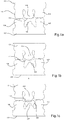
- Figure 1 a shows an upper digital dental model (upper model) 101 and lower digital dental model (lower model) 102.
- the digital dental models represents a section of a patients jaw and have been acquired by scanning the respective section of the jaw with an intra oral scanner, for example the TRIOS manufactured by 3Shape TRIOS.
- the digital dental models could also be obtained from scanning a physical impression or a gypsum model, which both are method known in the art for obtaining digital dental models.
- the upper model 101 has digital representations of three molar teeth 103, 104, 105 and the lower model 102 has digital representations of two molar teeth 106, 107 separated by a target site 108 which in this case is a prepared tooth.
- the dynamic occlusion of the jaw is found by placing the dental models in a virtual/digital articulator.
- virtual articulators are well known and are computer driven simulations and representations of physical articulators, which are used to estimate the jaw movement and occlusion of a patient.
- an occlusion surface 110 is found by tracing the surface of the middle molar 104 opposing the preparation during dynamic occlusion.
- the occlusion surface is subsequently offset 111 a desired distance towards the target site along axis A - A as shown in Fig. 1 b.
- a restoration such as a crown 109 as shown in Fig. 1c with a digital anatomy design is now modelled on the prepared tooth 108 using the offset occlusion surface 111 and the neighboring teeth 106, 107 as design boundaries.
- the digital anatomy design is thus retracted and therefore does not interfere with the occlusion of the existing teeth represented by teeth models 102, 103, 104, 105, 106 and 107.
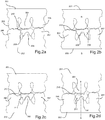
- an upper digital dental model (upper model) 201 and lower digital dental model (lower model) 202 is obtained, for example by means as previously described above.
- the upper model 201 has digital representations of three molar teeth 203, 204, 205 and the lower model 202 has digital representations of two molar teeth 206, 207 separated by a target site 208 which in this case is a prepared tooth as shown in Fig. 2a .
- An occlusion surface 210 is provided by virtual articulation as discussed previously, e.g. in connection with figures 1a - 1c above.
- An intermediate anatomy design 209 of the restoration is provided on the target site.
- a relative offset of the intermediate anatomy design 209 is provided as shown in Fig. 2b by offsetting the intermediate anatomy design 209 along axis B - B away from the target site 208.
- the intermediate anatomy design 209 is modified as shown in Fig. 2c .
- the modified anatomy design 211 is placed on the target site 208 and the dental technician can verify the fit e.g. against the neighboring teeth 206 and 207 and provide further modifications if necessary.
- the disclosed method provides a retracted digital anatomy design that does not interfere with the occlusion of the existing teeth represented by teeth models 202, 203, 204, 205, 206 and 207.
- a 3D representation of an upper model of the jaw 301 and the lower model of the jaw 302 is obtained.
- An upper model 301 is provided and has digital representations of three molar teeth 303, 304, 305 and the lower model 302 has digital representations of two molar teeth 306, 307 separates by a target site 308 which in this case is a prepared tooth.
- An occlusion surface 310 is provided by virtually articulating the jaws and tracing the surface of the molar tooth representation 304 during dynamic occlusion, for example as previously described.
- An intermediate anatomy design 309 of a dental restoration is designed using the antagonist tooth 304, the occlusion surface 310 and the neighboring teeth 306 and 307 as design boundaries.
- the occlusion surface 310 is offset 312 by shifting it towards the target site 308 along line C - C as shown in Fig. 3b .
- a modified anatomy design 311 is subsequently provided by using the offset occlusion surface 312 as a design boundary.
- the method for digitally designing a restoration is provided on computation means for executing the method before a user, such as a dental technician.
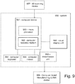
- the method is provided in a computer system as shown in Fig.9 .
- the computer system 950 comprises a computer device 951 comprising a computer readable medium 952 and a processor 953.
- the system further comprises a visual display unit 956, a computer keyboard 954 and a computer mouse 955 for entering data and activating virtual buttons visualized on the visual display unit 956.
- the visual display unit 956 can be a computer screen/monitor.
- the computer device 951 is capable of receiving a digital 3D representation of the patient's set of teeth from a scanning device 957, such as the TRIOS intra-oral scanner manufactured by 3shape A/S, or capable of receiving scan data from such a scanning device and forming a digital 3D representation of the patient's set of teeth based on such scan data.
- the received or formed digital 3D representation can be stored in the computer readable medium 952 and provided to the processor 953.
- the processor 953 is configured for executing computer code that allows for the steps of the method for digitally designing a restoration as disclosed herein. The user is guided through the method steps via a user interface visualized on the visual display unit 956.
- the computer system comprises a unit 958 for transmitting the virtual 3D model to e.g. a computer aided manufacturing (CAM) device 959 for manufacturing the dental restoration or to another computer system e.g. located at a milling center where the dental restoration is manufactured.
- the unit for transmitting the virtual 3D model can be a wired or a wireless connection.
- a cloud based system can be implemented.
- data used for the design steps can be stored remotely on external servers.
- Such servers could be placed abroad and accessed via the Internet.
- the process, or parts thereof, could also be executed on the external servers, such that the user is simply presented with the result of such processes on a visual display unit while the processing occurs remotely.
Landscapes
- Health & Medical Sciences (AREA)
- Life Sciences & Earth Sciences (AREA)
- Public Health (AREA)
- Veterinary Medicine (AREA)
- General Health & Medical Sciences (AREA)
- Animal Behavior & Ethology (AREA)
- Oral & Maxillofacial Surgery (AREA)
- Dentistry (AREA)
- Epidemiology (AREA)
- Engineering & Computer Science (AREA)
- Biophysics (AREA)
- Biomedical Technology (AREA)
- Theoretical Computer Science (AREA)
- Physics & Mathematics (AREA)
- Computer Hardware Design (AREA)
- Evolutionary Computation (AREA)
- General Physics & Mathematics (AREA)
- General Engineering & Computer Science (AREA)
- Geometry (AREA)
- Dental Tools And Instruments Or Auxiliary Dental Instruments (AREA)
- Architecture (AREA)
- Software Systems (AREA)
Abstract


Description
- This invention generally relates to digitally designing a dental restoration. In particular it relates to a method for digitally designing a dental restoration where the risk that the dental restoration interferes with the current occlusion/bite of the patient is reduced.
- When doing restorative work on a patient the dentist always has to be careful not to alter the occlusion of the patient. A changed occlusion may result in a change in chewing motion and bite and may cause discomfort or even pain.
- Accordingly, it is a desire to prevent, or at least reduce the risk, that the occlusion is altered during restorative work.
- Disclosed is a method for digitally designing a dental restoration, comprising:
- obtaining a 3D representation of at least a part of an upper or lower jaw of a patient, representing at least a target site for placing the restoration and at least one antagonist tooth opposing the target site,
- providing a digital anatomy design of the restoration based at least on a dynamic occlusion and a relative offset of the planned restoration position.
- This has the effect that the anatomy design of the dental restoration can be designed slightly lower than the surrounding teeth and thus the occlusion of the patient is maintained.
- It has even been shown that in many cases the restoration, if it is based on a natural tooth, will naturally move towards the antagonist until in contact during occlusion.
- Accordingly, a restoration may be designed that does not interrupt the natural occlusion and in many cases will in time place itself in a natural position.
- Unless specifically stated herein any reference to occlusion should be understood as dynamic occlusion, i.e. the contact between teeth during movement of a jaws when closed. For example, occlusion does not refer to static occlusion.
- In one embodiment the step of providing the digital anatomy design comprises,
- determining an occlusion boundary defined by the at least one antagonist tooth during the dynamic occlusion,
- providing the relative offset by offsetting the occlusion boundary relative to the target site,
- generating the digital anatomy design within the occlusion boundary and the neighboring teeth.
- This advantageously allows the design of the digital anatomy design in one step, basically automating the anatomy design step.
- In other situations, it may be desirable to modify an existing design.
- Accordingly, in another embodiment the method comprises the steps of,
- designing at least an intermediate anatomy of the restoration, and
- determining contact areas between the at least one antagonist tooth and the intermediate anatomy of the restoration based on the dynamic occlusion and the relative offset,
- generating the anatomy design of the restoration by modifying the shape of the intermediate anatomy of the restoration at least in the contact areas.
- In one embodiment the relative offset is provided by arranging the intermediate anatomy with a predetermined offset distance away from the target site.
- This is particularly advantageous as it allows the contact areas to be determined by performing the dynamic occlusion while the intermediate anatomy is arranged in a relative offset away from the target site.
- In yet another embodiment the relative offset is represented as a threshold distance applied for determining the contact areas during dynamic occlusion.
- In one embodiment, the method further comprises that
- the contact areas are determined by establishing an occlusion surface by tracing the relative teeth movement opposite the target site during dynamic occlusion, and providing the relative offset by offsetting the occlusion surface towards the target site, and
- that the anatomy design is generated by using the offset occlusion surface as a cutting surface on the intermediate anatomy.
- In addition, when providing an occlusion surface it is not necessary to rerun the dynamic occlusion every time changes are done to the anatomy design, since the occlusion surface shows if there are any areas that need to be modified or reshaped/remodeled.
- In general the relative offset can be provided in many different ways, for example the relative offset is provided by offsetting the target site relative to the jaw, or by offsetting the intermediate anatomy relative to the antagonist, or by offsetting the intermediate anatomy relative to the target site.
- Disclosed is also a nontransitory computer readable medium storing thereon a computer program, where said computer program is configured for executing the steps of the method disclosed herein.
- The above and/or additional objects, features and advantages of the present invention, will be further elucidated by the following illustrative and nonlimiting detailed description of embodiments of the present invention, with reference to the appended drawings, wherein:
-
Fig. 1 a - 1 c shows the design steps of a method according to one embodiment of the invention, -
Fig. 2a - 1d shows the design steps of a method according to another embodiment of the invention, -
Fig. 3a - 3c shows the design steps of a method according to yet another embodiment of the invention, and -
Fig. 9 shows an embodiment of computer system suitable for working the method disclosed herein. -
Figure 1 a shows an upper digital dental model (upper model) 101 and lower digital dental model (lower model) 102. The digital dental models represents a section of a patients jaw and have been acquired by scanning the respective section of the jaw with an intra oral scanner, for example the TRIOS manufactured by 3Shape TRIOS. The digital dental models could also be obtained from scanning a physical impression or a gypsum model, which both are method known in the art for obtaining digital dental models. - The
upper model 101 has digital representations of threemolar teeth lower model 102 has digital representations of twomolar teeth target site 108 which in this case is a prepared tooth. - The dynamic occlusion of the jaw is found by placing the dental models in a virtual/digital articulator. Such virtual articulators are well known and are computer driven simulations and representations of physical articulators, which are used to estimate the jaw movement and occlusion of a patient. By using the representations of the existing
teeth occlusion surface 110 is found by tracing the surface of themiddle molar 104 opposing the preparation during dynamic occlusion. - The occlusion surface is subsequently offset 111 a desired distance towards the target site along axis A - A as shown in
Fig. 1 b. - A restoration, such as a
crown 109 as shown inFig. 1c with a digital anatomy design is now modelled on the preparedtooth 108 using theoffset occlusion surface 111 and the neighboringteeth - As can be understood, the digital anatomy design is thus retracted and therefore does not interfere with the occlusion of the existing teeth represented by
teeth models - In another embodiment an upper digital dental model (upper model) 201 and lower digital dental model (lower model) 202 is obtained, for example by means as previously described above.
- The
upper model 201 has digital representations of threemolar teeth lower model 202 has digital representations of twomolar teeth target site 208 which in this case is a prepared tooth as shown inFig. 2a . - An
occlusion surface 210 is provided by virtual articulation as discussed previously, e.g. in connection withfigures 1a - 1c above. - An
intermediate anatomy design 209 of the restoration is provided on the target site. - A relative offset of the
intermediate anatomy design 209 is provided as shown inFig. 2b by offsetting theintermediate anatomy design 209 along axis B - B away from thetarget site 208. - Based on the
occlusion surface 210 theintermediate anatomy design 209 is modified as shown inFig. 2c . This results in a modifiedanatomy design 211, which follows the constraints applied by the software as a result of theocclusion surface 210. - Subsequently, as shown in
Fig. 2d , the modifiedanatomy design 211 is placed on thetarget site 208 and the dental technician can verify the fit e.g. against the neighboringteeth - As previously discussed the disclosed method provides a retracted digital anatomy design that does not interfere with the occlusion of the existing teeth represented by
teeth models - In a third embodiment as shown in
Figs. 3a - 3c the digital steps for designing a restoration are shown. - A 3D representation of an upper model of the
jaw 301 and the lower model of thejaw 302 is obtained. E.g. as disclosed previously in connection with other embodiments or as known in the art. Anupper model 301 is provided and has digital representations of threemolar teeth lower model 302 has digital representations of twomolar teeth target site 308 which in this case is a prepared tooth. - An
occlusion surface 310 is provided by virtually articulating the jaws and tracing the surface of themolar tooth representation 304 during dynamic occlusion, for example as previously described. - An
intermediate anatomy design 309 of a dental restoration is designed using theantagonist tooth 304, theocclusion surface 310 and the neighboringteeth - The
occlusion surface 310 is offset 312 by shifting it towards thetarget site 308 along line C - C as shown inFig. 3b . - A modified
anatomy design 311 is subsequently provided by using the offsetocclusion surface 312 as a design boundary. - Again, the digital anatomy design is thus retracted and therefore does not interfere with the occlusion of the existing teeth represented by
teeth models - Other embodiments of digital design methods for providing a digital anatomy design as disclosed herein may be provided within the scope of the claimed invention.
- The method for digitally designing a restoration is provided on computation means for executing the method before a user, such as a dental technician.
- For example, the method is provided in a computer system as shown in
Fig.9 . Thecomputer system 950 comprises acomputer device 951 comprising a computerreadable medium 952 and aprocessor 953. The system further comprises avisual display unit 956, acomputer keyboard 954 and a computer mouse 955 for entering data and activating virtual buttons visualized on thevisual display unit 956. Thevisual display unit 956 can be a computer screen/monitor. Thecomputer device 951 is capable of receiving a digital 3D representation of the patient's set of teeth from ascanning device 957, such as the TRIOS intra-oral scanner manufactured by 3shape A/S, or capable of receiving scan data from such a scanning device and forming a digital 3D representation of the patient's set of teeth based on such scan data. The received or formed digital 3D representation can be stored in the computerreadable medium 952 and provided to theprocessor 953. Theprocessor 953 is configured for executing computer code that allows for the steps of the method for digitally designing a restoration as disclosed herein. The user is guided through the method steps via a user interface visualized on thevisual display unit 956. - The computer system comprises a
unit 958 for transmitting the virtual 3D model to e.g. a computer aided manufacturing (CAM)device 959 for manufacturing the dental restoration or to another computer system e.g. located at a milling center where the dental restoration is manufactured. The unit for transmitting the virtual 3D model can be a wired or a wireless connection. - Alternatively, or in combination with the computer system as disclosed a cloud based system can be implemented. For example data used for the design steps can be stored remotely on external servers. Such servers could be placed abroad and accessed via the Internet. Even further, the process, or parts thereof, could also be executed on the external servers, such that the user is simply presented with the result of such processes on a visual display unit while the processing occurs remotely.
- Although some embodiments have been described and shown in detail, the invention is not restricted to them, but may also be embodied in other ways within the scope of the subject matter defined in the following claims. In particular, it is to be understood that other embodiments may be utilised and structural and functional modifications may be made without departing from the scope of the present invention.
Claims (10)
- A method for digitally designing a dental restoration, comprising:- obtaining a 3D representation of at least a part of an upper or lower jaw of a patient, representing at least a target site for placing the restoration and at least one antagonist tooth opposing the target site,- providing a digital anatomy design of the restoration based at least on a dynamic occlusion and a relative offset of the planned restoration position.
- A method according to claim 1, wherein the step of providing the digital anatomy design comprises,- determining an occlusion boundary defined by the at least one antagonist tooth during the dynamic occlusion,- providing the relative offset by offsetting the occlusion boundary relative to the target site,- generating the digital anatomy design within the occlusion boundary and the neighboring teeth.
- A method according to claim 1, wherein the method further comprises the steps of,- designing at least an intermediate anatomy of the restoration, andwherein the step of providing a digital anatomy design further comprises the steps of,- determining contact areas between the at least one antagonist tooth and the intermediate anatomy of the restoration based on the dynamic occlusion and the relative offset,- generating the anatomy design of the restoration by modifying the shape of the intermediate anatomy of the restoration at least in the contact areas.
- A method according to claim 3, wherein the relative offset is provided by arranging the intermediate anatomy with a predetermined offset distance away from the target site.
- A method according to claim 4, wherein the contact areas are determined by performing the dynamic occlusion while the intermediate anatomy is arranged in a relative offset away from the target site.
- A method according to claim 3, wherein the relative offset is represented as a threshold distance applied for determining the contact areas during dynamic occlusion.
- A method according to claim 3, further comprising that- the contact areas are determined by establishing an occlusion surface by tracing the relative teeth movement opposite the target site during dynamic occlusion, and providing the relative offset by offsetting the occlusion surface towards the target site, and- that the anatomy design is generated by using the offset occlusion surface as a cutting surface on the intermediate anatomy.
- A method according to claim 1 or 3, wherein the relative offset is provided by offsetting the target site relative to the jaw.
- A method according to claim 3, wherein the relative offset is provided by offsetting the intermediate anatomy relative to the antagonist.
- A method according to claim 3, wherein the relative offset is provided by offsetting the intermediate anatomy relative to the target site.
Applications Claiming Priority (1)
| Application Number | Priority Date | Filing Date | Title |
|---|---|---|---|
| DKPA201670139 | 2016-03-10 |
Publications (2)
| Publication Number | Publication Date |
|---|---|
| EP3216419A1 true EP3216419A1 (en) | 2017-09-13 |
| EP3216419B1 EP3216419B1 (en) | 2019-06-05 |
Family
ID=58265866
Family Applications (1)
| Application Number | Title | Priority Date | Filing Date |
|---|---|---|---|
| EP17160031.5A Active EP3216419B1 (en) | 2016-03-10 | 2017-03-09 | Method for digital designing a dental restoration |
Country Status (3)
| Country | Link |
|---|---|
| US (1) | US10251731B2 (en) |
| EP (1) | EP3216419B1 (en) |
| ES (1) | ES2733472T3 (en) |
Cited By (3)
| Publication number | Priority date | Publication date | Assignee | Title |
|---|---|---|---|---|
| CN111150507A (en) * | 2020-01-19 | 2020-05-15 | 四川大学 | A method for transferring occlusal relationship and morphological design in dental occlusal reconstruction and restoration |
| US11318000B2 (en) * | 2018-01-30 | 2022-05-03 | Dio Corporation | Digital dental prosthesis and method for manufacturing same |
| WO2023152303A1 (en) * | 2022-02-10 | 2023-08-17 | Exocad Gmbh | Guiding surface generation |
Families Citing this family (1)
| Publication number | Priority date | Publication date | Assignee | Title |
|---|---|---|---|---|
| US20220409337A1 (en) * | 2019-09-27 | 2022-12-29 | Pusan National University Industry-University Cooperation Foundation | Method for manufacturing implant shape for minimizing the stress applied to implant by using computer, and method and apparatus for recommending optimal occlusal area for implant by using computer |
Citations (3)
| Publication number | Priority date | Publication date | Assignee | Title |
|---|---|---|---|---|
| JPH0549651A (en) * | 1991-08-29 | 1993-03-02 | Nikon Corp | Dental prosthesis design device |
| WO2011103876A1 (en) * | 2010-02-25 | 2011-09-01 | 3Shape A/S | Dynamic virtual articulator |
| DE102012104373A1 (en) * | 2012-05-21 | 2013-12-05 | Albert Mehl | Method for simulating motion of e.g. upper jaw, for optimizing tooth restorations of male patient in clinic, involves directly determining movement parameters of upper jaw and/or lower jaw from measurement records of upper and lower jaws |
Family Cites Families (7)
| Publication number | Priority date | Publication date | Assignee | Title |
|---|---|---|---|---|
| GB0328239D0 (en) | 2003-12-05 | 2004-01-07 | Renishaw Plc | Manufacture of dental prostheses |
| US7819662B2 (en) | 2004-11-30 | 2010-10-26 | Geodigm Corporation | Multi-component dental appliances and a method for constructing the same |
| US20090068617A1 (en) * | 2006-03-03 | 2009-03-12 | Lauren Mark D | Method Of Designing Dental Devices Using Four-Dimensional Data |
| EP2422742B1 (en) | 2010-08-31 | 2013-05-22 | Straumann Holding AG | Computer-implemented method for digitally designing a dental restoration |
| EP3777756B1 (en) * | 2012-02-14 | 2025-04-09 | 3Shape A/S | Modeling a digital design of a denture |
| EP2974690B1 (en) * | 2013-03-11 | 2019-01-09 | Fujitsu Limited | Program for design of dental prostheses, device for design of dental prostheses, and method for design of dental prostheses |
| JP6262179B2 (en) * | 2014-12-05 | 2018-01-17 | ディオ コーポレーションDio Corporation | Surgical guide for dental implant operation and method for manufacturing planted plant |
-
2017
- 2017-03-09 ES ES17160031T patent/ES2733472T3/en active Active
- 2017-03-09 EP EP17160031.5A patent/EP3216419B1/en active Active
- 2017-03-10 US US15/455,735 patent/US10251731B2/en active Active
Patent Citations (3)
| Publication number | Priority date | Publication date | Assignee | Title |
|---|---|---|---|---|
| JPH0549651A (en) * | 1991-08-29 | 1993-03-02 | Nikon Corp | Dental prosthesis design device |
| WO2011103876A1 (en) * | 2010-02-25 | 2011-09-01 | 3Shape A/S | Dynamic virtual articulator |
| DE102012104373A1 (en) * | 2012-05-21 | 2013-12-05 | Albert Mehl | Method for simulating motion of e.g. upper jaw, for optimizing tooth restorations of male patient in clinic, involves directly determining movement parameters of upper jaw and/or lower jaw from measurement records of upper and lower jaws |
Cited By (5)
| Publication number | Priority date | Publication date | Assignee | Title |
|---|---|---|---|---|
| US11318000B2 (en) * | 2018-01-30 | 2022-05-03 | Dio Corporation | Digital dental prosthesis and method for manufacturing same |
| CN111150507A (en) * | 2020-01-19 | 2020-05-15 | 四川大学 | A method for transferring occlusal relationship and morphological design in dental occlusal reconstruction and restoration |
| CN111150507B (en) * | 2020-01-19 | 2021-09-17 | 四川大学 | Method for transferring occlusion relation and morphological design in dental occlusion reconstruction restoration |
| WO2023152303A1 (en) * | 2022-02-10 | 2023-08-17 | Exocad Gmbh | Guiding surface generation |
| US11980511B2 (en) | 2022-02-10 | 2024-05-14 | Exocad Gmbh | Guiding surface generation |
Also Published As
| Publication number | Publication date |
|---|---|
| US20170258561A1 (en) | 2017-09-14 |
| ES2733472T3 (en) | 2019-11-29 |
| EP3216419B1 (en) | 2019-06-05 |
| US10251731B2 (en) | 2019-04-09 |
Similar Documents
| Publication | Publication Date | Title |
|---|---|---|
| US11478330B2 (en) | Dental preparation guide | |
| US20240335253A1 (en) | System For Preparing Teeth For The Placement Of Veneers | |
| US10327873B2 (en) | Method, system and user interface for creating a digital design for use in manufacturing a molding-shell for a dental restoration | |
| EP3478218B1 (en) | Virtual model of articulation from intra-oral scans | |
| EP3223740B1 (en) | Method of digitally designing a modified dental setup | |
| EP3197389B1 (en) | Creating a digital restoration design | |
| KR101413222B1 (en) | An image matching data creation method for orthodontics and remote mock treatment method and providing the information for orthodontics device using the same | |
| US10251731B2 (en) | Method for digital designing a dental restoration | |
| KR101249688B1 (en) | Image matching data creation method for orthognathic surgery and orthodontic treatment simulation and manufacturing information providing method for surgey device using the same | |
| US12426998B2 (en) | Snapping of denture teeth | |
| KR20130044932A (en) | An image matching method for orthodontics and production method for orthodontics device using the same | |
| KR101872393B1 (en) | Personalized tooth modeling method | |
| CN110831540A (en) | Systems and methods for the design and improved retention of orthodontic aligners | |
| KR101801827B1 (en) | Surgical guide system and method | |
| WO2016102451A1 (en) | Using a cbct bone scan to design a dental abutment | |
| KR102332451B1 (en) | Method and apparatus for generation of mandibular movement model |
Legal Events
| Date | Code | Title | Description |
|---|---|---|---|
| PUAI | Public reference made under article 153(3) epc to a published international application that has entered the european phase |
Free format text: ORIGINAL CODE: 0009012 |
|
| STAA | Information on the status of an ep patent application or granted ep patent |
Free format text: STATUS: THE APPLICATION HAS BEEN PUBLISHED |
|
| AK | Designated contracting states |
Kind code of ref document: A1 Designated state(s): AL AT BE BG CH CY CZ DE DK EE ES FI FR GB GR HR HU IE IS IT LI LT LU LV MC MK MT NL NO PL PT RO RS SE SI SK SM TR |
|
| AX | Request for extension of the european patent |
Extension state: BA ME |
|
| STAA | Information on the status of an ep patent application or granted ep patent |
Free format text: STATUS: REQUEST FOR EXAMINATION WAS MADE |
|
| 17P | Request for examination filed |
Effective date: 20180228 |
|
| RBV | Designated contracting states (corrected) |
Designated state(s): AL AT BE BG CH CY CZ DE DK EE ES FI FR GB GR HR HU IE IS IT LI LT LU LV MC MK MT NL NO PL PT RO RS SE SI SK SM TR |
|
| GRAP | Despatch of communication of intention to grant a patent |
Free format text: ORIGINAL CODE: EPIDOSNIGR1 |
|
| STAA | Information on the status of an ep patent application or granted ep patent |
Free format text: STATUS: GRANT OF PATENT IS INTENDED |
|
| INTG | Intention to grant announced |
Effective date: 20181217 |
|
| GRAS | Grant fee paid |
Free format text: ORIGINAL CODE: EPIDOSNIGR3 |
|
| GRAA | (expected) grant |
Free format text: ORIGINAL CODE: 0009210 |
|
| STAA | Information on the status of an ep patent application or granted ep patent |
Free format text: STATUS: THE PATENT HAS BEEN GRANTED |
|
| AK | Designated contracting states |
Kind code of ref document: B1 Designated state(s): AL AT BE BG CH CY CZ DE DK EE ES FI FR GB GR HR HU IE IS IT LI LT LU LV MC MK MT NL NO PL PT RO RS SE SI SK SM TR |
|
| REG | Reference to a national code |
Ref country code: GB Ref legal event code: FG4D |
|
| REG | Reference to a national code |
Ref country code: CH Ref legal event code: EP |
|
| REG | Reference to a national code |
Ref country code: AT Ref legal event code: REF Ref document number: 1139236 Country of ref document: AT Kind code of ref document: T Effective date: 20190615 |
|
| REG | Reference to a national code |
Ref country code: IE Ref legal event code: FG4D |
|
| REG | Reference to a national code |
Ref country code: DE Ref legal event code: R096 Ref document number: 602017004252 Country of ref document: DE |
|
| REG | Reference to a national code |
Ref country code: NL Ref legal event code: FP |
|
| REG | Reference to a national code |
Ref country code: LT Ref legal event code: MG4D |
|
| PG25 | Lapsed in a contracting state [announced via postgrant information from national office to epo] |
Ref country code: FI Free format text: LAPSE BECAUSE OF FAILURE TO SUBMIT A TRANSLATION OF THE DESCRIPTION OR TO PAY THE FEE WITHIN THE PRESCRIBED TIME-LIMIT Effective date: 20190605 Ref country code: NO Free format text: LAPSE BECAUSE OF FAILURE TO SUBMIT A TRANSLATION OF THE DESCRIPTION OR TO PAY THE FEE WITHIN THE PRESCRIBED TIME-LIMIT Effective date: 20190905 Ref country code: LT Free format text: LAPSE BECAUSE OF FAILURE TO SUBMIT A TRANSLATION OF THE DESCRIPTION OR TO PAY THE FEE WITHIN THE PRESCRIBED TIME-LIMIT Effective date: 20190605 Ref country code: HR Free format text: LAPSE BECAUSE OF FAILURE TO SUBMIT A TRANSLATION OF THE DESCRIPTION OR TO PAY THE FEE WITHIN THE PRESCRIBED TIME-LIMIT Effective date: 20190605 Ref country code: SE Free format text: LAPSE BECAUSE OF FAILURE TO SUBMIT A TRANSLATION OF THE DESCRIPTION OR TO PAY THE FEE WITHIN THE PRESCRIBED TIME-LIMIT Effective date: 20190605 Ref country code: AL Free format text: LAPSE BECAUSE OF FAILURE TO SUBMIT A TRANSLATION OF THE DESCRIPTION OR TO PAY THE FEE WITHIN THE PRESCRIBED TIME-LIMIT Effective date: 20190605 |
|
| PG25 | Lapsed in a contracting state [announced via postgrant information from national office to epo] |
Ref country code: RS Free format text: LAPSE BECAUSE OF FAILURE TO SUBMIT A TRANSLATION OF THE DESCRIPTION OR TO PAY THE FEE WITHIN THE PRESCRIBED TIME-LIMIT Effective date: 20190605 Ref country code: LV Free format text: LAPSE BECAUSE OF FAILURE TO SUBMIT A TRANSLATION OF THE DESCRIPTION OR TO PAY THE FEE WITHIN THE PRESCRIBED TIME-LIMIT Effective date: 20190605 Ref country code: GR Free format text: LAPSE BECAUSE OF FAILURE TO SUBMIT A TRANSLATION OF THE DESCRIPTION OR TO PAY THE FEE WITHIN THE PRESCRIBED TIME-LIMIT Effective date: 20190906 Ref country code: BG Free format text: LAPSE BECAUSE OF FAILURE TO SUBMIT A TRANSLATION OF THE DESCRIPTION OR TO PAY THE FEE WITHIN THE PRESCRIBED TIME-LIMIT Effective date: 20190905 |
|
| REG | Reference to a national code |
Ref country code: ES Ref legal event code: FG2A Ref document number: 2733472 Country of ref document: ES Kind code of ref document: T3 Effective date: 20191129 |
|
| REG | Reference to a national code |
Ref country code: AT Ref legal event code: MK05 Ref document number: 1139236 Country of ref document: AT Kind code of ref document: T Effective date: 20190605 |
|
| PG25 | Lapsed in a contracting state [announced via postgrant information from national office to epo] |
Ref country code: CZ Free format text: LAPSE BECAUSE OF FAILURE TO SUBMIT A TRANSLATION OF THE DESCRIPTION OR TO PAY THE FEE WITHIN THE PRESCRIBED TIME-LIMIT Effective date: 20190605 Ref country code: PT Free format text: LAPSE BECAUSE OF FAILURE TO SUBMIT A TRANSLATION OF THE DESCRIPTION OR TO PAY THE FEE WITHIN THE PRESCRIBED TIME-LIMIT Effective date: 20191007 Ref country code: SK Free format text: LAPSE BECAUSE OF FAILURE TO SUBMIT A TRANSLATION OF THE DESCRIPTION OR TO PAY THE FEE WITHIN THE PRESCRIBED TIME-LIMIT Effective date: 20190605 Ref country code: AT Free format text: LAPSE BECAUSE OF FAILURE TO SUBMIT A TRANSLATION OF THE DESCRIPTION OR TO PAY THE FEE WITHIN THE PRESCRIBED TIME-LIMIT Effective date: 20190605 Ref country code: EE Free format text: LAPSE BECAUSE OF FAILURE TO SUBMIT A TRANSLATION OF THE DESCRIPTION OR TO PAY THE FEE WITHIN THE PRESCRIBED TIME-LIMIT Effective date: 20190605 Ref country code: RO Free format text: LAPSE BECAUSE OF FAILURE TO SUBMIT A TRANSLATION OF THE DESCRIPTION OR TO PAY THE FEE WITHIN THE PRESCRIBED TIME-LIMIT Effective date: 20190605 |
|
| PG25 | Lapsed in a contracting state [announced via postgrant information from national office to epo] |
Ref country code: IS Free format text: LAPSE BECAUSE OF FAILURE TO SUBMIT A TRANSLATION OF THE DESCRIPTION OR TO PAY THE FEE WITHIN THE PRESCRIBED TIME-LIMIT Effective date: 20191005 Ref country code: SM Free format text: LAPSE BECAUSE OF FAILURE TO SUBMIT A TRANSLATION OF THE DESCRIPTION OR TO PAY THE FEE WITHIN THE PRESCRIBED TIME-LIMIT Effective date: 20190605 |
|
| REG | Reference to a national code |
Ref country code: DE Ref legal event code: R097 Ref document number: 602017004252 Country of ref document: DE |
|
| PG25 | Lapsed in a contracting state [announced via postgrant information from national office to epo] |
Ref country code: TR Free format text: LAPSE BECAUSE OF FAILURE TO SUBMIT A TRANSLATION OF THE DESCRIPTION OR TO PAY THE FEE WITHIN THE PRESCRIBED TIME-LIMIT Effective date: 20190605 |
|
| PLBE | No opposition filed within time limit |
Free format text: ORIGINAL CODE: 0009261 |
|
| STAA | Information on the status of an ep patent application or granted ep patent |
Free format text: STATUS: NO OPPOSITION FILED WITHIN TIME LIMIT |
|
| PG25 | Lapsed in a contracting state [announced via postgrant information from national office to epo] |
Ref country code: PL Free format text: LAPSE BECAUSE OF FAILURE TO SUBMIT A TRANSLATION OF THE DESCRIPTION OR TO PAY THE FEE WITHIN THE PRESCRIBED TIME-LIMIT Effective date: 20190605 Ref country code: DK Free format text: LAPSE BECAUSE OF FAILURE TO SUBMIT A TRANSLATION OF THE DESCRIPTION OR TO PAY THE FEE WITHIN THE PRESCRIBED TIME-LIMIT Effective date: 20190605 |
|
| 26N | No opposition filed |
Effective date: 20200306 |
|
| PG25 | Lapsed in a contracting state [announced via postgrant information from national office to epo] |
Ref country code: SI Free format text: LAPSE BECAUSE OF FAILURE TO SUBMIT A TRANSLATION OF THE DESCRIPTION OR TO PAY THE FEE WITHIN THE PRESCRIBED TIME-LIMIT Effective date: 20190605 |
|
| PG25 | Lapsed in a contracting state [announced via postgrant information from national office to epo] |
Ref country code: MC Free format text: LAPSE BECAUSE OF FAILURE TO SUBMIT A TRANSLATION OF THE DESCRIPTION OR TO PAY THE FEE WITHIN THE PRESCRIBED TIME-LIMIT Effective date: 20190605 |
|
| REG | Reference to a national code |
Ref country code: CH Ref legal event code: PL |
|
| REG | Reference to a national code |
Ref country code: BE Ref legal event code: MM Effective date: 20200331 |
|
| PG25 | Lapsed in a contracting state [announced via postgrant information from national office to epo] |
Ref country code: LU Free format text: LAPSE BECAUSE OF NON-PAYMENT OF DUE FEES Effective date: 20200309 |
|
| PG25 | Lapsed in a contracting state [announced via postgrant information from national office to epo] |
Ref country code: CH Free format text: LAPSE BECAUSE OF NON-PAYMENT OF DUE FEES Effective date: 20200331 Ref country code: IE Free format text: LAPSE BECAUSE OF NON-PAYMENT OF DUE FEES Effective date: 20200309 Ref country code: LI Free format text: LAPSE BECAUSE OF NON-PAYMENT OF DUE FEES Effective date: 20200331 |
|
| PG25 | Lapsed in a contracting state [announced via postgrant information from national office to epo] |
Ref country code: BE Free format text: LAPSE BECAUSE OF NON-PAYMENT OF DUE FEES Effective date: 20200331 |
|
| PG25 | Lapsed in a contracting state [announced via postgrant information from national office to epo] |
Ref country code: MT Free format text: LAPSE BECAUSE OF FAILURE TO SUBMIT A TRANSLATION OF THE DESCRIPTION OR TO PAY THE FEE WITHIN THE PRESCRIBED TIME-LIMIT Effective date: 20190605 Ref country code: CY Free format text: LAPSE BECAUSE OF FAILURE TO SUBMIT A TRANSLATION OF THE DESCRIPTION OR TO PAY THE FEE WITHIN THE PRESCRIBED TIME-LIMIT Effective date: 20190605 |
|
| PGFP | Annual fee paid to national office [announced via postgrant information from national office to epo] |
Ref country code: NL Payment date: 20220321 Year of fee payment: 6 |
|
| PG25 | Lapsed in a contracting state [announced via postgrant information from national office to epo] |
Ref country code: MK Free format text: LAPSE BECAUSE OF FAILURE TO SUBMIT A TRANSLATION OF THE DESCRIPTION OR TO PAY THE FEE WITHIN THE PRESCRIBED TIME-LIMIT Effective date: 20190605 |
|
| P01 | Opt-out of the competence of the unified patent court (upc) registered |
Effective date: 20230529 |
|
| REG | Reference to a national code |
Ref country code: NL Ref legal event code: MM Effective date: 20230401 |
|
| PG25 | Lapsed in a contracting state [announced via postgrant information from national office to epo] |
Ref country code: NL Free format text: LAPSE BECAUSE OF NON-PAYMENT OF DUE FEES Effective date: 20230401 |
|
| PGFP | Annual fee paid to national office [announced via postgrant information from national office to epo] |
Ref country code: ES Payment date: 20250429 Year of fee payment: 9 |
|
| PGFP | Annual fee paid to national office [announced via postgrant information from national office to epo] |
Ref country code: GB Payment date: 20260223 Year of fee payment: 10 |
|
| PGFP | Annual fee paid to national office [announced via postgrant information from national office to epo] |
Ref country code: DE Payment date: 20260223 Year of fee payment: 10 |
|
| PGFP | Annual fee paid to national office [announced via postgrant information from national office to epo] |
Ref country code: IT Payment date: 20260227 Year of fee payment: 10 |
|
| PGFP | Annual fee paid to national office [announced via postgrant information from national office to epo] |
Ref country code: FR Payment date: 20260223 Year of fee payment: 10 |