EP3214725B1 - Spacesuit with battery - Google Patents
Spacesuit with battery Download PDFInfo
- Publication number
- EP3214725B1 EP3214725B1 EP17158076.4A EP17158076A EP3214725B1 EP 3214725 B1 EP3214725 B1 EP 3214725B1 EP 17158076 A EP17158076 A EP 17158076A EP 3214725 B1 EP3214725 B1 EP 3214725B1
- Authority
- EP
- European Patent Office
- Prior art keywords
- battery
- cells
- battery cell
- switch
- cell
- Prior art date
- Legal status (The legal status is an assumption and is not a legal conclusion. Google has not performed a legal analysis and makes no representation as to the accuracy of the status listed.)
- Active
Links
Images


Classifications
-
- B—PERFORMING OPERATIONS; TRANSPORTING
- B64—AIRCRAFT; AVIATION; COSMONAUTICS
- B64G—COSMONAUTICS; VEHICLES OR EQUIPMENT THEREFOR
- B64G6/00—Space suits
-
- H—ELECTRICITY
- H02—GENERATION; CONVERSION OR DISTRIBUTION OF ELECTRIC POWER
- H02J—ELECTRIC POWER NETWORKS; CIRCUIT ARRANGEMENTS OR SYSTEMS FOR SUPPLYING OR DISTRIBUTING ELECTRIC POWER; SYSTEMS FOR STORING ELECTRIC ENERGY
- H02J7/00—Circuit arrangements for charging or discharging batteries or for supplying loads from batteries
- H02J7/50—Circuit arrangements for charging or discharging batteries or for supplying loads from batteries acting upon multiple batteries simultaneously or sequentially
- H02J7/52—Circuit arrangements for charging or discharging batteries or for supplying loads from batteries acting upon multiple batteries simultaneously or sequentially for charge balancing, e.g. equalisation of charge between batteries
- H02J7/54—Passive balancing, e.g. using resistors or parallel MOSFETs
-
- H—ELECTRICITY
- H02—GENERATION; CONVERSION OR DISTRIBUTION OF ELECTRIC POWER
- H02J—ELECTRIC POWER NETWORKS; CIRCUIT ARRANGEMENTS OR SYSTEMS FOR SUPPLYING OR DISTRIBUTING ELECTRIC POWER; SYSTEMS FOR STORING ELECTRIC ENERGY
- H02J7/00—Circuit arrangements for charging or discharging batteries or for supplying loads from batteries
- H02J7/855—Circuit arrangements for charging or discharging batteries or for supplying loads from batteries with circuits adapted for supplying loads from the battery
-
- H—ELECTRICITY
- H02—GENERATION; CONVERSION OR DISTRIBUTION OF ELECTRIC POWER
- H02J—ELECTRIC POWER NETWORKS; CIRCUIT ARRANGEMENTS OR SYSTEMS FOR SUPPLYING OR DISTRIBUTING ELECTRIC POWER; SYSTEMS FOR STORING ELECTRIC ENERGY
- H02J7/00—Circuit arrangements for charging or discharging batteries or for supplying loads from batteries
- H02J7/90—Regulation of charging or discharging current or voltage
- H02J7/933—Regulation of charging or discharging current or voltage the cycle being controlled or terminated in response to electric parameters
-
- H—ELECTRICITY
- H01—ELECTRIC ELEMENTS
- H01M—PROCESSES OR MEANS, e.g. BATTERIES, FOR THE DIRECT CONVERSION OF CHEMICAL ENERGY INTO ELECTRICAL ENERGY
- H01M10/00—Secondary cells; Manufacture thereof
- H01M10/42—Methods or arrangements for servicing or maintenance of secondary cells or secondary half-cells
- H01M10/48—Accumulators combined with arrangements for measuring, testing or indicating the condition of cells, e.g. the level or density of the electrolyte
- H01M10/482—Accumulators combined with arrangements for measuring, testing or indicating the condition of cells, e.g. the level or density of the electrolyte for several batteries or cells simultaneously or sequentially
-
- H—ELECTRICITY
- H01—ELECTRIC ELEMENTS
- H01M—PROCESSES OR MEANS, e.g. BATTERIES, FOR THE DIRECT CONVERSION OF CHEMICAL ENERGY INTO ELECTRICAL ENERGY
- H01M10/00—Secondary cells; Manufacture thereof
- H01M10/42—Methods or arrangements for servicing or maintenance of secondary cells or secondary half-cells
- H01M10/425—Structural combination with electronic components, e.g. electronic circuits integrated to the outside of the casing
- H01M2010/4271—Battery management systems including electronic circuits, e.g. control of current or voltage to keep battery in healthy state, cell balancing
-
- Y—GENERAL TAGGING OF NEW TECHNOLOGICAL DEVELOPMENTS; GENERAL TAGGING OF CROSS-SECTIONAL TECHNOLOGIES SPANNING OVER SEVERAL SECTIONS OF THE IPC; TECHNICAL SUBJECTS COVERED BY FORMER USPC CROSS-REFERENCE ART COLLECTIONS [XRACs] AND DIGESTS
- Y02—TECHNOLOGIES OR APPLICATIONS FOR MITIGATION OR ADAPTATION AGAINST CLIMATE CHANGE
- Y02E—REDUCTION OF GREENHOUSE GAS [GHG] EMISSIONS, RELATED TO ENERGY GENERATION, TRANSMISSION OR DISTRIBUTION
- Y02E60/00—Enabling technologies; Technologies with a potential or indirect contribution to GHG emissions mitigation
- Y02E60/10—Energy storage using batteries
Definitions
- This application relates to batteries, and more particularly to a battery control circuit that controls whether battery cells are connected to each other.
- Electrical batteries can be used to provide electrical power to devices within specific voltage and current ranges. Electrical batteries are composed of cells connected in series and/or in parallel. The individual cells of a battery provide a voltage which primarily depends on the chemicals composition of the cells. The design of a given cell limits the voltage and current that the cell is able to provide. Connecting additional cells in parallel increases the current output of a battery, and connecting additional cells in series increases a voltage output of a battery.
- KR 20070091814 A relates to a battery having a square part unit.
- US 2013302657 A1 relates to a storage battery system and method of re-configuring a connection.
- US 2004055067 A1 relates to an apparatus and method for putting on a protective suit.
- One aspect of the invention relates to a battery circuit as defined in claim 1. Another aspect of the invention relates to a method of controlling battery cells as defined in claim 2.
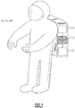
- FIG. 1 schematically illustrates a space suit 10 that includes a battery 12 that powers a load 14.
- the battery comprises a plurality of cells 16 that can be selectively connected in series or in parallel to power the load 14.
- the load 14 may include components such as a motor for cooling and/or distributing air within the space suit 10, for example.
- the space suit 10 also includes a controller 22 that is configured to measure an output of the cells 16 and control which ones of the cells 16 are connected to each other and the load 14.
- a first subset of the battery cells 16 are primary cells that are initially connected in parallel to each other and to the load 14, and a different, second subset of the battery cells 16 are spare cells that are initially disconnected from each other and the first subset of battery cells.
- the controller 22 is able to disconnect primary cells, and connect spare cells as needed. This is especially valuable in space suits, as space walks are logistically challenging to plan, and it would be very burdensome for an astronaut to have to travel back to a space craft during a spacewalk because of a battery failure.
- Fig. 2A schematically illustrates an example circuit 20 for controlling which cells 16 are used in a battery, such as the battery 12.
- Battery cells 16A-D are included, and are connectable in parallel between a shared input node 25 and a shared output node 29.
- Each of the cells 16A-D has an associated switch 18 that controls whether its associated battery cell 16 is connected in parallel to other ones of the battery cells 16 (between nodes 25 and 29) and to the load 14, or is disconnected from the load 14 and the other battery cells 16.
- each switch 18 is connected in series between the output of its battery cell 16 (i.e., its positive terminal) and node 29.
- one or more of the switches 18 could instead be located between the input node 25 and the input of its battery cell 16 (i.e., its negative terminal).
- Controller 22 is operative to control the switches 18 via control lines 23 to selectively connect and disconnect the cells 16 from each other and from the load 14. This can be done based on a detected condition in the cells, such as a diminished voltage and/or current of a given cell 16, for example. Such a condition can be detected via measurement lines 24.
- the controller 22 monitors the output voltages of the cells 16, and is configured to recognize when a voltage of a given cell falls beneath a predefined voltage threshold (or a current of a given cell falls beneath a predefined current threshold).
- cells 16A-C are primary cells that are initially connected (i.e., switches 18A-C are ON), and that cell 16D is a spare cell that is initially disconnected (i.e., switch 18D is OFF).
- the controller 22 detects that an output voltage of cell 16C falls beneath a predefined voltage threshold. If no action is taken, the cell 16C may absorb current from the other cells 16-B, heating the cell 16C and further degrading its condition. To avoid this, the controller may turn OFF switch 18C, which disconnects the cell 16C from cells 16A-B and from the load 14, and turn ON switch 18D to connect cell 16D in its place. This enables the battery 12 to maintain a desired output without relying on depleted cells.
- the controller 22 is configured to control the switches 18 to maintain a predefined quantity of the battery cells 16 in parallel connection with each other (e.g., three cells in Fig. 2A ). Although only four cells have been illustrated and discussed above (e.g., three of which are primary and one of which is a spare), it is understood that any number of cells could be used, and that different quantities of those could be configured as primary cells and spare cells.
- no switches 18 are included between the input node 25 the inputs of the cells (i.e., their negative terminals).
- a single switch for each cell is operative to control whether its associated cell 16 is connected.
- the switches 118 could be relocated to be connected in series between the input node 125 and the inputs of the cells 116. There is no switch between the cell 116 and output node 129. Such a configuration may increase an ON resistance of the switch 118 as compared to the configuration depicted in Fig. 2A for switch 18.
- the controller 22 includes a measurement circuit 26 that is connected to the input (negative) and output (positive) terminals of each of the cells 16 via measurement lines 24.
- the measurement circuit 26 utilizes a multiplexor to alternate for which of the cells 16 it is performing measurements.
- the measurements may be voltage and/or current measurements, for example.
- the measurement circuit 26 may include an analog-to-digital converter to provide digital voltage and/or current values for comparison to a predefined threshold.
- the controller 22 may include a microprocessor and associated memory (not shown) to perform such comparisons.
- the controller 22 also includes a switching control circuit 27 that controls the state of each switch 18 via the control lines 23, which are connected to the gate of each switch 18A-D to control whether the individual switches 18A-D are ON or OFF.
- Fig. 3A schematically illustrates another example circuit 28 for controlling which cells 16 are used in a battery 12.
- battery cells 16A-D are included, and each of the cells 16A-D has a respective input node 34 and output node 36.
- Each battery cell 16A-D also has an associated pair of switches 30, 32 that are configured to implement either a first configuration in which the input and output nodes 34, 36 connect the battery cell 16 in series with other ones of the battery cells 16, or a second configuration in which the input and output nodes 34, 36 are connected via a respective bypass line 38 and the battery cell 16 is disconnected from the other battery cells.
- a first, connection switch 30 of its pair of switches is situated between its input node 34 and an input terminal of the given battery cell (i.e., its negative terminal), and a second, bypass switch 32 of its pair of switches is part of the bypass line 38.
- a given cell 16 to be in the first configuration its associated switch 30 is ON and its associated switch 32 is OFF.
- a cell 16 to be in the second configuration its switch 30 is turned OFF and its switch 32 is turned ON.
- the first switch 130 is instead situated between an output terminal of the battery cell (i.e., its positive terminal) and its output node 136, and there is no switch between the cell 116 and its input node 134.
- Controller 22' is configured to control the switches 30, 32 such that a first subset of the battery cells 16 are primary cells that are initially connected in series to each other, and a different, second subset of the battery cells 16 are spare cells that are initially disconnected from each other and the first subset of battery cells.
- cells 16A-C are primary cells that are initially connected (i.e., switches 30A-C are ON, and switches 32A-C are turned OFF), and that cell 16D is a spare cell that is initially disconnected (i.e., switch 30D is OFF, and switch 32D is ON).
- the controller 22' detects that the output voltage of cell 16C falls beneath a predefined voltage threshold. Based on this detection, the controller 22' turns switch 30C OFF, and turns switch 32C ON, which connects nodes 34C, 36C via bypass line 38 and disconnects cell 16C from the other cells 16A-B and from the load 14. The controller 22' also connects cell 16D to the other cells 16A-B by turning switch 30D ON and turning switch 32D OFF. This enables the battery 12 to maintain a desired output without relying on depleted cells 16.
- Controller 22' includes a switching control circuit 27' that is configured to control the switches 18 via control lines 23' to selectively connect and disconnect the cells 16 from each other and from the load.
- the controller 22' also includes a measurement circuit 26' that is configured to measure an output of each of the cells 16 via measurement lines 24' (e.g., voltage and/or current measurements).
- measurement lines 24' e.g., voltage and/or current measurements.
- analog-to-digital converter, microprocessor, and memory may be included in the measurement circuit 26'.
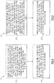
- Fig. 4 is a flowchart of a method 100 for controlling a plurality of battery cells 16 connected in parallel that may be used in conjunction with the circuit of Fig. 2A or 2B .
- An output of one or more of a plurality of battery cells 16 is measured (e.g., an output voltage or current) (block 102).
- Each of the cells 16 are connectable in parallel between an input node 25 and an output node 29.
- Each battery cell has an associated switch 18 that controls whether the battery cell 16 is connected in parallel to the load 14 and with other ones of the battery cells 16 via a shared input node 25 and a shared output node 29, or is disconnected from the load 14 and the other battery cells 16.
- Each switch 18 is connected in series either between the input node 25 and an input of its associated battery cell 16 (i.e., its negative terminal) or between the output node 29 and an output of its associated battery cell 16 (i.e., its positive terminal).
- the switches are controlled (block 104) to selectively disconnect a first one of the battery cells 16 from the load 14 and the other battery cells 16, and connect a second, disconnected one of the battery cells 16 to the load 14 and the other battery cells 16 based on the measuring of block 102.
- Fig. 5 is a flowchart of a method 200 for controlling a plurality of battery cells 16 connected in series that may be used in conjunction with the circuit of Fig. 3A or 3B .
- An output of one or more of a plurality of battery cells 16 is measured (e.g., an output voltage or current) (block 202).
- Each of the battery cells 16 has a respective input node 34 and output node 36, and each of the battery cells 16 also has an associated pair of switches 30, 32 that are configured to implement either a first configuration in which the input and output nodes 34, 36 connect the battery cell 16 in series with other ones of the battery cells 16, or a second configuration in which the input and output nodes 34, 36 are connected via a respective bypass line 38 and the battery cell 16 is disconnected from the other ones of the battery cells 16.
- the pairs of switches 30, 32 are controlled (block 204) to selectively reconfigure a first one of the battery cells to the second configuration and reconfigure a second, disconnected one of the battery cells to the first configuration based on the measuring.
- the various embodiments discussed above facilitate disconnection of a depleted battery cell, which can preserve the power in the rest of the cells of a battery 12, and also facilitate connection of a spare battery cell to maintain a desired battery output. This can be particularly useful for space suits where consistent and reliable power is needed.
- the embodiments discussed above also enable use of a small number of switches to implement the disclosed functionality, which enables complexity reduction in circuit design and an increase in reliability.
Landscapes
- Engineering & Computer Science (AREA)
- Power Engineering (AREA)
- Remote Sensing (AREA)
- Aviation & Aerospace Engineering (AREA)
- Charge And Discharge Circuits For Batteries Or The Like (AREA)
- Secondary Cells (AREA)
- Professional, Industrial, Or Sporting Protective Garments (AREA)
Description
- This application relates to batteries, and more particularly to a battery control circuit that controls whether battery cells are connected to each other.
- Electrical batteries can be used to provide electrical power to devices within specific voltage and current ranges. Electrical batteries are composed of cells connected in series and/or in parallel. The individual cells of a battery provide a voltage which primarily depends on the chemicals composition of the cells. The design of a given cell limits the voltage and current that the cell is able to provide. Connecting additional cells in parallel increases the current output of a battery, and connecting additional cells in series increases a voltage output of a battery.
- As battery cells become depleted, their output will decay. However, the rate of output decay may not be uniform among the cells. This can cause output from the stronger cells to go into the decayed cells rather than to powering a device, which occurs when cells are not close in voltage. This may result in damage to the decayed cells, reduced output from the battery, and/or early failure of the battery.
KR 20070091814 A US 2013302657 A1 relates to a storage battery system and method of re-configuring a connection.US 2004055067 A1 relates to an apparatus and method for putting on a protective suit. - One aspect of the invention relates to a battery circuit as defined in claim 1. Another aspect of the invention relates to a method of controlling battery cells as defined in claim 2.
-
-
Fig. 1 schematically illustrates a space suit that includes a battery having a plurality of cells. -
Fig. 2A schematically illustrates an example parallel circuit for controlling which cells are used in a battery. -
Fig. 2B shows an alternative circuit with control at the negative side of a cell. -
Fig. 3A schematically illustrates another example circuit for controlling which cells in series are used in a battery. -
Fig. 3B shows an alternative circuit with control at both sides of the cell. -
Fig. 4 is a flowchart of a method that may be used in conjunction with the circuit ofFigs. 2A or 2B . -
Fig. 5 is a flowchart of a method that may be used in conjunction with the circuit ofFigs. 3A or 3B . - The embodiments described herein may be taken independently or in any combination. Features described in connection with one embodiment are applicable to all embodiments, unless such features are incompatible.
-
Figure 1 schematically illustrates aspace suit 10 that includes abattery 12 that powers aload 14. The battery comprises a plurality ofcells 16 that can be selectively connected in series or in parallel to power theload 14. Theload 14 may include components such as a motor for cooling and/or distributing air within thespace suit 10, for example. Thespace suit 10 also includes acontroller 22 that is configured to measure an output of thecells 16 and control which ones of thecells 16 are connected to each other and theload 14. A first subset of thebattery cells 16 are primary cells that are initially connected in parallel to each other and to theload 14, and a different, second subset of thebattery cells 16 are spare cells that are initially disconnected from each other and the first subset of battery cells. Thecontroller 22 is able to disconnect primary cells, and connect spare cells as needed. This is especially valuable in space suits, as space walks are logistically challenging to plan, and it would be very burdensome for an astronaut to have to travel back to a space craft during a spacewalk because of a battery failure. -
Fig. 2A schematically illustrates anexample circuit 20 for controlling whichcells 16 are used in a battery, such as thebattery 12.Battery cells 16A-D are included, and are connectable in parallel between a shared input node 25 and a sharedoutput node 29. Each of thecells 16A-D has an associated switch 18 that controls whether its associatedbattery cell 16 is connected in parallel to other ones of the battery cells 16 (between nodes 25 and 29) and to theload 14, or is disconnected from theload 14 and theother battery cells 16. In the example ofFig. 2A , each switch 18 is connected in series between the output of its battery cell 16 (i.e., its positive terminal) andnode 29. However, as discussed below, one or more of the switches 18 could instead be located between the input node 25 and the input of its battery cell 16 (i.e., its negative terminal). -
Controller 22 is operative to control the switches 18 viacontrol lines 23 to selectively connect and disconnect thecells 16 from each other and from theload 14. This can be done based on a detected condition in the cells, such as a diminished voltage and/or current of a givencell 16, for example. Such a condition can be detected viameasurement lines 24. In one example, thecontroller 22 monitors the output voltages of thecells 16, and is configured to recognize when a voltage of a given cell falls beneath a predefined voltage threshold (or a current of a given cell falls beneath a predefined current threshold). - For the discussion below, assume that
cells 16A-C are primary cells that are initially connected (i.e.,switches 18A-C are ON), and thatcell 16D is a spare cell that is initially disconnected (i.e.,switch 18D is OFF). Say thecontroller 22 detects that an output voltage ofcell 16C falls beneath a predefined voltage threshold. If no action is taken, thecell 16C may absorb current from the other cells 16-B, heating thecell 16C and further degrading its condition. To avoid this, the controller may turnOFF switch 18C, which disconnects thecell 16C fromcells 16A-B and from theload 14, and turn ONswitch 18D to connectcell 16D in its place. This enables thebattery 12 to maintain a desired output without relying on depleted cells. - In one or more embodiments, the
controller 22 is configured to control the switches 18 to maintain a predefined quantity of thebattery cells 16 in parallel connection with each other (e.g., three cells inFig. 2A ). Although only four cells have been illustrated and discussed above (e.g., three of which are primary and one of which is a spare), it is understood that any number of cells could be used, and that different quantities of those could be configured as primary cells and spare cells. - In the example of
Fig. 2A , no switches 18 are included between the input node 25 the inputs of the cells (i.e., their negative terminals). In this regard, a single switch for each cell is operative to control whether itsassociated cell 16 is connected. - In an alternative configuration, shown in
Fig. 2B , theswitches 118 could be relocated to be connected in series between theinput node 125 and the inputs of thecells 116. There is no switch between thecell 116 andoutput node 129. Such a configuration may increase an ON resistance of theswitch 118 as compared to the configuration depicted inFig. 2A for switch 18. - The
controller 22 includes ameasurement circuit 26 that is connected to the input (negative) and output (positive) terminals of each of thecells 16 via measurement lines 24. In one example, themeasurement circuit 26 utilizes a multiplexor to alternate for which of thecells 16 it is performing measurements. The measurements may be voltage and/or current measurements, for example. Themeasurement circuit 26 may include an analog-to-digital converter to provide digital voltage and/or current values for comparison to a predefined threshold. Thecontroller 22 may include a microprocessor and associated memory (not shown) to perform such comparisons. - The
controller 22 also includes a switchingcontrol circuit 27 that controls the state of each switch 18 via thecontrol lines 23, which are connected to the gate of eachswitch 18A-D to control whether theindividual switches 18A-D are ON or OFF. -
Fig. 3A schematically illustrates anotherexample circuit 28 for controlling whichcells 16 are used in abattery 12. InFig. 3A ,battery cells 16A-D are included, and each of thecells 16A-D has a respective input node 34 and output node 36. Eachbattery cell 16A-D also has an associated pair of switches 30, 32 that are configured to implement either a first configuration in which the input and output nodes 34, 36 connect thebattery cell 16 in series with other ones of thebattery cells 16, or a second configuration in which the input and output nodes 34, 36 are connected via a respective bypass line 38 and thebattery cell 16 is disconnected from the other battery cells. - For each of the
battery cells 16 inFig. 3A , a first, connection switch 30 of its pair of switches is situated between its input node 34 and an input terminal of the given battery cell (i.e., its negative terminal), and a second, bypass switch 32 of its pair of switches is part of the bypass line 38. For a givencell 16 to be in the first configuration, its associated switch 30 is ON and its associated switch 32 is OFF. For thatcell 16 to be in the second configuration, its switch 30 is turned OFF and its switch 32 is turned ON. - In an alternative configuration, shown in
Fig. 3B , thefirst switch 130 is instead situated between an output terminal of the battery cell (i.e., its positive terminal) and its output node 136, and there is no switch between thecell 116 and itsinput node 134. - Controller 22' is configured to control the switches 30, 32 such that a first subset of the
battery cells 16 are primary cells that are initially connected in series to each other, and a different, second subset of thebattery cells 16 are spare cells that are initially disconnected from each other and the first subset of battery cells. For the discussion below, assume thatcells 16A-C are primary cells that are initially connected (i.e., switches 30A-C are ON, and switches 32A-C are turned OFF), and thatcell 16D is a spare cell that is initially disconnected (i.e., switch 30D is OFF, and switch 32D is ON). - Assume also that the controller 22' detects that the output voltage of
cell 16C falls beneath a predefined voltage threshold. Based on this detection, the controller 22' turns switch 30C OFF, and turns switch 32C ON, which connectsnodes cell 16C from theother cells 16A-B and from theload 14. The controller 22' also connectscell 16D to theother cells 16A-B by turningswitch 30D ON and turning switch 32D OFF. This enables thebattery 12 to maintain a desired output without relying on depletedcells 16. - Here too, although only four cells have been illustrated and discussed above (e.g., three of which are primary and one of which is a spare), it is understood that any number of cells could be used, and that different quantities of those could be configured as primary cells and spare cells.
- Controller 22' includes a switching control circuit 27' that is configured to control the switches 18 via control lines 23' to selectively connect and disconnect the
cells 16 from each other and from the load. The controller 22' also includes a measurement circuit 26' that is configured to measure an output of each of thecells 16 via measurement lines 24' (e.g., voltage and/or current measurements). As in the previous example, and analog-to-digital converter, microprocessor, and memory may be included in the measurement circuit 26'. -
Fig. 4 is a flowchart of amethod 100 for controlling a plurality ofbattery cells 16 connected in parallel that may be used in conjunction with the circuit ofFig. 2A or 2B . An output of one or more of a plurality ofbattery cells 16 is measured (e.g., an output voltage or current) (block 102). Each of thecells 16 are connectable in parallel between an input node 25 and anoutput node 29. Each battery cell has an associated switch 18 that controls whether thebattery cell 16 is connected in parallel to theload 14 and with other ones of thebattery cells 16 via a shared input node 25 and a sharedoutput node 29, or is disconnected from theload 14 and theother battery cells 16. Each switch 18 is connected in series either between the input node 25 and an input of its associated battery cell 16 (i.e., its negative terminal) or between theoutput node 29 and an output of its associated battery cell 16 (i.e., its positive terminal). The switches are controlled (block 104) to selectively disconnect a first one of thebattery cells 16 from theload 14 and theother battery cells 16, and connect a second, disconnected one of thebattery cells 16 to theload 14 and theother battery cells 16 based on the measuring ofblock 102. -
Fig. 5 is a flowchart of amethod 200 for controlling a plurality ofbattery cells 16 connected in series that may be used in conjunction with the circuit ofFig. 3A or 3B . An output of one or more of a plurality ofbattery cells 16 is measured (e.g., an output voltage or current) (block 202). Each of thebattery cells 16 has a respective input node 34 and output node 36, and each of thebattery cells 16 also has an associated pair of switches 30, 32 that are configured to implement either a first configuration in which the input and output nodes 34, 36 connect thebattery cell 16 in series with other ones of thebattery cells 16, or a second configuration in which the input and output nodes 34, 36 are connected via a respective bypass line 38 and thebattery cell 16 is disconnected from the other ones of thebattery cells 16. The pairs of switches 30, 32 are controlled (block 204) to selectively reconfigure a first one of the battery cells to the second configuration and reconfigure a second, disconnected one of the battery cells to the first configuration based on the measuring. - The various embodiments discussed above facilitate disconnection of a depleted battery cell, which can preserve the power in the rest of the cells of a
battery 12, and also facilitate connection of a spare battery cell to maintain a desired battery output. This can be particularly useful for space suits where consistent and reliable power is needed. - The embodiments discussed above also enable use of a small number of switches to implement the disclosed functionality, which enables complexity reduction in circuit design and an increase in reliability.
Claims (2)
- A spacesuit (10) comprising:a battery configured to power a load, the battery comprising a plurality of battery cells (16A-D); characterized in that at least one of the battery cells is connected and at least one of the battery cells is disconnected; and further characterized by comprisinga first switch (18, 30) configured to disconnect a particular one of the at least one connected battery cells;a second switch (18, 32) configured to connect a particular one of the at least one disconnected battery cells; anda controller (22, 22') that is configured to monitor for a diminished current or voltage condition in the plurality of battery cells (16A-D), and to control the first and second switches based on a detected diminished current or voltage condition in the particular connected battery cell: wherein the battery circuit (28) comprises a plurality of switches (30A-D, 18A-D, 32A-D), including the first and second switches (18, 30, 32), each associated with a respective battery cell (16A-D), and wherein the controller (22) is configured to control the plurality of switches to maintain a predefined quantity of the battery cells (16A-D) in connection with each other, and wherein the detected condition in the particular connected battery cell (16A-D) comprises an output of the particular connected battery cell being below a predefined threshold; andwherein the at least one connected battery cell (16A-D) and the at least one disconnected battery cell are part of a plurality of battery cells, each of which has an associated switch (18) that controls whether the battery cell (16A-D) is connected in parallel to a load and other ones of the battery cells (16A-D) via a shared input node (25) and a shared output node (29), or is disconnected from the load and the other battery cells, each switch being connected in series between its associated battery cell and either the shared input node (25) or the shared output node (29); andwherein the first switch (18) is the associated switch for the particular connected battery cell, and the second switch (18) is the associated switch for the particular disconnected battery cell;wherein for each battery cell the associated switch is the only switch that is situated between either of the shared input node and input of the battery cell or the shared output node and output of the battery cell.
- A method of controlling battery cells of a battery in a space suit (10) comprising:detecting a diminished current or voltage condition in at least one connected battery cell (16A-D); andbased on the detecting:controlling a first switch (18, 30) to disconnect a particular one of the at least one connected battery cells; andcontrolling a second switch (18, 32) to connect a particular one of at least one disconnected battery cell (16A-D); andcontrolling a plurality of switches (30A-D, 18A-D, 32A-D), including the first and second switches (18, 30, 32), each associated with a respective battery cell (16A-D) of a plurality of battery cells, which includes the at least one connected battery cell and the at least one disconnected battery cell, to maintain a predefined quantity of the battery cells (16A-D) in connection with each other and a load;wherein each switch controls whether its associated battery cell is connected in parallel to the load and other battery cells via a shared input node (25) and a shared output node (29), or is disconnected from the load and the other battery cells, each switch being connected in series between its associated battery cell and either the shared input node (25) or the shared output node (29);wherein the detecting comprises: measuring an output of the particular connected battery cell (16A-D); and detecting, based on the measuring, that an output of the particular connected battery cell (16A-D) is below a predefined threshold; wherein for each battery cell, the associated switch is the only switch that is situated between either of the shared input node and input of the battery cell or the shared output node of the battery cell.
Applications Claiming Priority (1)
| Application Number | Priority Date | Filing Date | Title |
|---|---|---|---|
| US15/060,986 US10305296B2 (en) | 2016-03-04 | 2016-03-04 | Intelligent battery self repair |
Publications (2)
| Publication Number | Publication Date |
|---|---|
| EP3214725A1 EP3214725A1 (en) | 2017-09-06 |
| EP3214725B1 true EP3214725B1 (en) | 2019-09-18 |
Family
ID=58185385
Family Applications (1)
| Application Number | Title | Priority Date | Filing Date |
|---|---|---|---|
| EP17158076.4A Active EP3214725B1 (en) | 2016-03-04 | 2017-02-27 | Spacesuit with battery |
Country Status (3)
| Country | Link |
|---|---|
| US (1) | US10305296B2 (en) |
| EP (1) | EP3214725B1 (en) |
| JP (1) | JP6853693B2 (en) |
Families Citing this family (2)
| Publication number | Priority date | Publication date | Assignee | Title |
|---|---|---|---|---|
| US11016140B1 (en) * | 2018-10-31 | 2021-05-25 | Wisk Aero Llc | Battery diode fault monitoring |
| US11611241B2 (en) * | 2021-05-17 | 2023-03-21 | Hamilton Sundstrand Corporation | Wireless power transfer to an extravehicular mobility unit |
Family Cites Families (29)
| Publication number | Priority date | Publication date | Assignee | Title |
|---|---|---|---|---|
| US3588359A (en) * | 1968-12-11 | 1971-06-28 | Nasa | Protective suit having an audio transceiver |
| US5610495A (en) | 1994-06-20 | 1997-03-11 | Motorola, Inc. | Circuit and method of monitoring battery cells |
| US5710503A (en) | 1996-02-01 | 1998-01-20 | Aims Systems, Inc. | On-line battery monitoring system with defective cell detection capability |
| US5894212A (en) | 1997-09-19 | 1999-04-13 | Tarrytown Consulting, Inc. | Discharge monitoring and isolating system for batteries |
| US5898291A (en) | 1998-01-26 | 1999-04-27 | Space Systems/Loral, Inc. | Battery cell bypass topology |
| US6166549A (en) | 1998-12-31 | 2000-12-26 | Daimlerchrysler Corporation | Electronic circuit for measuring series connected electrochemical cell voltages |
| US7126310B1 (en) * | 2001-04-20 | 2006-10-24 | Abiomed, Inc. | Apparatus and method for balanced charging of a multiple-cell battery pack |
| US20030190510A1 (en) | 2002-04-04 | 2003-10-09 | James Musselman | Apparatus and method for monitoring individual cells in a fuel-cell based electrical power source |
| DE10232216A1 (en) | 2002-07-17 | 2004-02-05 | Astrium Gmbh | Device for putting on a protective suit |
| JP4196122B2 (en) | 2005-02-25 | 2008-12-17 | パナソニック株式会社 | Battery pack |
| US7586292B1 (en) | 2005-05-09 | 2009-09-08 | Electrochem Solutions, Inc. | Low voltage cutoff circuit for an electrochemical cell |
| KR100885243B1 (en) | 2006-03-07 | 2009-02-24 | 송기학 | Battery unit with spare battery unit |
| US8143851B2 (en) * | 2008-02-15 | 2012-03-27 | Apple Inc. | Power source having a parallel cell topology |
| JP2009213248A (en) * | 2008-03-04 | 2009-09-17 | Nec Corp | Battery device and control method therefor |
| JP5480520B2 (en) * | 2009-03-27 | 2014-04-23 | 伊藤忠商事株式会社 | Battery control device, vehicle, and battery control method |
| JP5722875B2 (en) | 2009-04-10 | 2015-05-27 | ザ リージェンツ オブ ザ ユニバーシティ オブ ミシガン | Dynamically reconfigurable structure for large battery systems |
| US8258792B2 (en) | 2009-05-11 | 2012-09-04 | Semiconductor Components Industries, Llc. | Monitoring system and method |
| US9246337B2 (en) * | 2010-04-23 | 2016-01-26 | Hitachi, Ltd. | Battery pack and battery pack controller |
| DE102010040721A1 (en) | 2010-09-14 | 2012-03-15 | Sb Limotive Company Ltd. | Battery system with cell voltage detection units |
| US8471529B2 (en) * | 2010-10-14 | 2013-06-25 | GM Global Technology Operations LLC | Battery fault tolerant architecture for cell failure modes parallel bypass circuit |
| JP2014063567A (en) * | 2011-01-26 | 2014-04-10 | Sony Corp | Battery pack and power consumption apparatus |
| KR101821334B1 (en) * | 2011-03-17 | 2018-03-08 | 이브이 칩 에너지 리미티드 | Battery Pack System |
| JP5248702B2 (en) * | 2011-09-14 | 2013-07-31 | 株式会社カワハラ技研 | Life support equipment |
| US9341678B2 (en) * | 2011-09-28 | 2016-05-17 | Alliance For Sustainable Energy, Llc | Fail-safe designs for large capacity battery systems |
| JP5667123B2 (en) | 2012-05-11 | 2015-02-12 | 株式会社東芝 | Storage battery system and connection configuration changing method |
| US9069027B2 (en) | 2012-07-17 | 2015-06-30 | Hycon Technology Corp. | Cell voltage monitoring and self-calibrating device |
| US20140167683A1 (en) | 2012-12-13 | 2014-06-19 | John Manford Wade | Multiple cell battery management |
| US9217781B2 (en) | 2014-01-16 | 2015-12-22 | Ford Global Technologies, Llc | Time synchronization between battery controller modules for parameter measurements |
| US9583792B2 (en) | 2014-06-11 | 2017-02-28 | Lenovo Enterprise Solutions (Singapore) Pte. Ltd. | Dynamically configurable auto-healing battery |
-
2016
- 2016-03-04 US US15/060,986 patent/US10305296B2/en active Active
-
2017
- 2017-02-27 EP EP17158076.4A patent/EP3214725B1/en active Active
- 2017-03-03 JP JP2017039986A patent/JP6853693B2/en active Active
Non-Patent Citations (1)
| Title |
|---|
| None * |
Also Published As
| Publication number | Publication date |
|---|---|
| JP2017158427A (en) | 2017-09-07 |
| US20170256963A1 (en) | 2017-09-07 |
| JP6853693B2 (en) | 2021-03-31 |
| EP3214725A1 (en) | 2017-09-06 |
| US10305296B2 (en) | 2019-05-28 |
Similar Documents
| Publication | Publication Date | Title |
|---|---|---|
| ES3037021T3 (en) | Apparatus and method for battery module equalization | |
| JP5020530B2 (en) | Charging method, battery pack and charger thereof | |
| EP3525314B1 (en) | Apparatus and method for preventing overcharge | |
| EP2517327B1 (en) | Battery energy storage system with short circuit protection, and method | |
| JP5748689B2 (en) | Battery system | |
| US7705605B2 (en) | Voltage detecting apparatus | |
| US20140210419A1 (en) | Battery pack and method for minimizing cell voltage deviations | |
| TW201539937A (en) | Battery system and method of operating battery system | |
| US20120306448A1 (en) | Charge balancing topology | |
| US9350168B2 (en) | Voltage equalization apparatus for connecting power storage unit racks and power storage system including the same | |
| KR20180119320A (en) | Apparatus and method for preventing overcharge | |
| EP3240097B1 (en) | Battery pack | |
| AU2008201759A1 (en) | Fail safe battery management system | |
| EP3214725A1 (en) | Intelligent battery self repair | |
| CN108258751B (en) | Charge/discharge control circuit and battery device | |
| US20150061595A1 (en) | Battery protection system and battery protection method using the same | |
| US20230055483A1 (en) | Discharging or charging of battery modules | |
| JP6880988B2 (en) | Battery monitoring integrated circuit device | |
| JP6959046B2 (en) | Charge / discharge control circuit and battery device | |
| KR102363568B1 (en) | Over charge protection system for battery module | |
| JP2023543886A (en) | Battery management device and method | |
| JP5440315B2 (en) | Battery module and module voltage balancing method using the battery module | |
| JP5781456B2 (en) | Power supply system | |
| JP2015146707A (en) | Power storage module controller and power storage module control method | |
| KR102745194B1 (en) | Appratus and method for measuring voltage of battery |
Legal Events
| Date | Code | Title | Description |
|---|---|---|---|
| PUAI | Public reference made under article 153(3) epc to a published international application that has entered the european phase |
Free format text: ORIGINAL CODE: 0009012 |
|
| STAA | Information on the status of an ep patent application or granted ep patent |
Free format text: STATUS: THE APPLICATION HAS BEEN PUBLISHED |
|
| AK | Designated contracting states |
Kind code of ref document: A1 Designated state(s): AL AT BE BG CH CY CZ DE DK EE ES FI FR GB GR HR HU IE IS IT LI LT LU LV MC MK MT NL NO PL PT RO RS SE SI SK SM TR |
|
| AX | Request for extension of the european patent |
Extension state: BA ME |
|
| STAA | Information on the status of an ep patent application or granted ep patent |
Free format text: STATUS: REQUEST FOR EXAMINATION WAS MADE |
|
| 17P | Request for examination filed |
Effective date: 20180306 |
|
| RBV | Designated contracting states (corrected) |
Designated state(s): AL AT BE BG CH CY CZ DE DK EE ES FI FR GB GR HR HU IE IS IT LI LT LU LV MC MK MT NL NO PL PT RO RS SE SI SK SM TR |
|
| STAA | Information on the status of an ep patent application or granted ep patent |
Free format text: STATUS: EXAMINATION IS IN PROGRESS |
|
| 17Q | First examination report despatched |
Effective date: 20180815 |
|
| GRAP | Despatch of communication of intention to grant a patent |
Free format text: ORIGINAL CODE: EPIDOSNIGR1 |
|
| STAA | Information on the status of an ep patent application or granted ep patent |
Free format text: STATUS: GRANT OF PATENT IS INTENDED |
|
| RIC1 | Information provided on ipc code assigned before grant |
Ipc: H02J 7/00 20060101AFI20190314BHEP Ipc: B64G 6/00 20060101ALN20190314BHEP Ipc: H01M 10/42 20060101ALN20190314BHEP Ipc: H01M 10/44 20060101ALN20190314BHEP Ipc: H01M 10/48 20060101ALN20190314BHEP |
|
| INTG | Intention to grant announced |
Effective date: 20190402 |
|
| GRAS | Grant fee paid |
Free format text: ORIGINAL CODE: EPIDOSNIGR3 |
|
| GRAA | (expected) grant |
Free format text: ORIGINAL CODE: 0009210 |
|
| STAA | Information on the status of an ep patent application or granted ep patent |
Free format text: STATUS: THE PATENT HAS BEEN GRANTED |
|
| AK | Designated contracting states |
Kind code of ref document: B1 Designated state(s): AL AT BE BG CH CY CZ DE DK EE ES FI FR GB GR HR HU IE IS IT LI LT LU LV MC MK MT NL NO PL PT RO RS SE SI SK SM TR |
|
| REG | Reference to a national code |
Ref country code: GB Ref legal event code: FG4D |
|
| REG | Reference to a national code |
Ref country code: CH Ref legal event code: EP |
|
| REG | Reference to a national code |
Ref country code: DE Ref legal event code: R096 Ref document number: 602017007064 Country of ref document: DE |
|
| REG | Reference to a national code |
Ref country code: AT Ref legal event code: REF Ref document number: 1182450 Country of ref document: AT Kind code of ref document: T Effective date: 20191015 |
|
| REG | Reference to a national code |
Ref country code: IE Ref legal event code: FG4D |
|
| REG | Reference to a national code |
Ref country code: NL Ref legal event code: MP Effective date: 20190918 |
|
| PG25 | Lapsed in a contracting state [announced via postgrant information from national office to epo] |
Ref country code: LT Free format text: LAPSE BECAUSE OF FAILURE TO SUBMIT A TRANSLATION OF THE DESCRIPTION OR TO PAY THE FEE WITHIN THE PRESCRIBED TIME-LIMIT Effective date: 20190918 Ref country code: HR Free format text: LAPSE BECAUSE OF FAILURE TO SUBMIT A TRANSLATION OF THE DESCRIPTION OR TO PAY THE FEE WITHIN THE PRESCRIBED TIME-LIMIT Effective date: 20190918 Ref country code: BG Free format text: LAPSE BECAUSE OF FAILURE TO SUBMIT A TRANSLATION OF THE DESCRIPTION OR TO PAY THE FEE WITHIN THE PRESCRIBED TIME-LIMIT Effective date: 20191218 Ref country code: NO Free format text: LAPSE BECAUSE OF FAILURE TO SUBMIT A TRANSLATION OF THE DESCRIPTION OR TO PAY THE FEE WITHIN THE PRESCRIBED TIME-LIMIT Effective date: 20191218 Ref country code: SE Free format text: LAPSE BECAUSE OF FAILURE TO SUBMIT A TRANSLATION OF THE DESCRIPTION OR TO PAY THE FEE WITHIN THE PRESCRIBED TIME-LIMIT Effective date: 20190918 Ref country code: FI Free format text: LAPSE BECAUSE OF FAILURE TO SUBMIT A TRANSLATION OF THE DESCRIPTION OR TO PAY THE FEE WITHIN THE PRESCRIBED TIME-LIMIT Effective date: 20190918 |
|
| REG | Reference to a national code |
Ref country code: LT Ref legal event code: MG4D |
|
| PG25 | Lapsed in a contracting state [announced via postgrant information from national office to epo] |
Ref country code: RS Free format text: LAPSE BECAUSE OF FAILURE TO SUBMIT A TRANSLATION OF THE DESCRIPTION OR TO PAY THE FEE WITHIN THE PRESCRIBED TIME-LIMIT Effective date: 20190918 Ref country code: GR Free format text: LAPSE BECAUSE OF FAILURE TO SUBMIT A TRANSLATION OF THE DESCRIPTION OR TO PAY THE FEE WITHIN THE PRESCRIBED TIME-LIMIT Effective date: 20191219 Ref country code: AL Free format text: LAPSE BECAUSE OF FAILURE TO SUBMIT A TRANSLATION OF THE DESCRIPTION OR TO PAY THE FEE WITHIN THE PRESCRIBED TIME-LIMIT Effective date: 20190918 Ref country code: LV Free format text: LAPSE BECAUSE OF FAILURE TO SUBMIT A TRANSLATION OF THE DESCRIPTION OR TO PAY THE FEE WITHIN THE PRESCRIBED TIME-LIMIT Effective date: 20190918 |
|
| REG | Reference to a national code |
Ref country code: AT Ref legal event code: MK05 Ref document number: 1182450 Country of ref document: AT Kind code of ref document: T Effective date: 20190918 |
|
| PG25 | Lapsed in a contracting state [announced via postgrant information from national office to epo] |
Ref country code: PT Free format text: LAPSE BECAUSE OF FAILURE TO SUBMIT A TRANSLATION OF THE DESCRIPTION OR TO PAY THE FEE WITHIN THE PRESCRIBED TIME-LIMIT Effective date: 20200120 Ref country code: PL Free format text: LAPSE BECAUSE OF FAILURE TO SUBMIT A TRANSLATION OF THE DESCRIPTION OR TO PAY THE FEE WITHIN THE PRESCRIBED TIME-LIMIT Effective date: 20190918 Ref country code: AT Free format text: LAPSE BECAUSE OF FAILURE TO SUBMIT A TRANSLATION OF THE DESCRIPTION OR TO PAY THE FEE WITHIN THE PRESCRIBED TIME-LIMIT Effective date: 20190918 Ref country code: NL Free format text: LAPSE BECAUSE OF FAILURE TO SUBMIT A TRANSLATION OF THE DESCRIPTION OR TO PAY THE FEE WITHIN THE PRESCRIBED TIME-LIMIT Effective date: 20190918 Ref country code: EE Free format text: LAPSE BECAUSE OF FAILURE TO SUBMIT A TRANSLATION OF THE DESCRIPTION OR TO PAY THE FEE WITHIN THE PRESCRIBED TIME-LIMIT Effective date: 20190918 Ref country code: IT Free format text: LAPSE BECAUSE OF FAILURE TO SUBMIT A TRANSLATION OF THE DESCRIPTION OR TO PAY THE FEE WITHIN THE PRESCRIBED TIME-LIMIT Effective date: 20190918 Ref country code: RO Free format text: LAPSE BECAUSE OF FAILURE TO SUBMIT A TRANSLATION OF THE DESCRIPTION OR TO PAY THE FEE WITHIN THE PRESCRIBED TIME-LIMIT Effective date: 20190918 Ref country code: ES Free format text: LAPSE BECAUSE OF FAILURE TO SUBMIT A TRANSLATION OF THE DESCRIPTION OR TO PAY THE FEE WITHIN THE PRESCRIBED TIME-LIMIT Effective date: 20190918 |
|
| PG25 | Lapsed in a contracting state [announced via postgrant information from national office to epo] |
Ref country code: SM Free format text: LAPSE BECAUSE OF FAILURE TO SUBMIT A TRANSLATION OF THE DESCRIPTION OR TO PAY THE FEE WITHIN THE PRESCRIBED TIME-LIMIT Effective date: 20190918 Ref country code: SK Free format text: LAPSE BECAUSE OF FAILURE TO SUBMIT A TRANSLATION OF THE DESCRIPTION OR TO PAY THE FEE WITHIN THE PRESCRIBED TIME-LIMIT Effective date: 20190918 Ref country code: IS Free format text: LAPSE BECAUSE OF FAILURE TO SUBMIT A TRANSLATION OF THE DESCRIPTION OR TO PAY THE FEE WITHIN THE PRESCRIBED TIME-LIMIT Effective date: 20200224 Ref country code: CZ Free format text: LAPSE BECAUSE OF FAILURE TO SUBMIT A TRANSLATION OF THE DESCRIPTION OR TO PAY THE FEE WITHIN THE PRESCRIBED TIME-LIMIT Effective date: 20190918 |
|
| REG | Reference to a national code |
Ref country code: DE Ref legal event code: R097 Ref document number: 602017007064 Country of ref document: DE |
|
| PLBE | No opposition filed within time limit |
Free format text: ORIGINAL CODE: 0009261 |
|
| STAA | Information on the status of an ep patent application or granted ep patent |
Free format text: STATUS: NO OPPOSITION FILED WITHIN TIME LIMIT |
|
| PG2D | Information on lapse in contracting state deleted |
Ref country code: IS |
|
| PG25 | Lapsed in a contracting state [announced via postgrant information from national office to epo] |
Ref country code: DK Free format text: LAPSE BECAUSE OF FAILURE TO SUBMIT A TRANSLATION OF THE DESCRIPTION OR TO PAY THE FEE WITHIN THE PRESCRIBED TIME-LIMIT Effective date: 20190918 Ref country code: IS Free format text: LAPSE BECAUSE OF FAILURE TO SUBMIT A TRANSLATION OF THE DESCRIPTION OR TO PAY THE FEE WITHIN THE PRESCRIBED TIME-LIMIT Effective date: 20200119 |
|
| 26N | No opposition filed |
Effective date: 20200619 |
|
| PG25 | Lapsed in a contracting state [announced via postgrant information from national office to epo] |
Ref country code: SI Free format text: LAPSE BECAUSE OF FAILURE TO SUBMIT A TRANSLATION OF THE DESCRIPTION OR TO PAY THE FEE WITHIN THE PRESCRIBED TIME-LIMIT Effective date: 20190918 |
|
| REG | Reference to a national code |
Ref country code: CH Ref legal event code: PL |
|
| REG | Reference to a national code |
Ref country code: BE Ref legal event code: MM Effective date: 20200229 |
|
| PG25 | Lapsed in a contracting state [announced via postgrant information from national office to epo] |
Ref country code: LU Free format text: LAPSE BECAUSE OF NON-PAYMENT OF DUE FEES Effective date: 20200227 Ref country code: MC Free format text: LAPSE BECAUSE OF FAILURE TO SUBMIT A TRANSLATION OF THE DESCRIPTION OR TO PAY THE FEE WITHIN THE PRESCRIBED TIME-LIMIT Effective date: 20190918 |
|
| PG25 | Lapsed in a contracting state [announced via postgrant information from national office to epo] |
Ref country code: CH Free format text: LAPSE BECAUSE OF NON-PAYMENT OF DUE FEES Effective date: 20200229 Ref country code: LI Free format text: LAPSE BECAUSE OF NON-PAYMENT OF DUE FEES Effective date: 20200229 |
|
| PG25 | Lapsed in a contracting state [announced via postgrant information from national office to epo] |
Ref country code: FR Free format text: LAPSE BECAUSE OF NON-PAYMENT OF DUE FEES Effective date: 20200229 Ref country code: IE Free format text: LAPSE BECAUSE OF NON-PAYMENT OF DUE FEES Effective date: 20200227 |
|
| PG25 | Lapsed in a contracting state [announced via postgrant information from national office to epo] |
Ref country code: BE Free format text: LAPSE BECAUSE OF NON-PAYMENT OF DUE FEES Effective date: 20200229 |
|
| PG25 | Lapsed in a contracting state [announced via postgrant information from national office to epo] |
Ref country code: TR Free format text: LAPSE BECAUSE OF FAILURE TO SUBMIT A TRANSLATION OF THE DESCRIPTION OR TO PAY THE FEE WITHIN THE PRESCRIBED TIME-LIMIT Effective date: 20190918 Ref country code: MT Free format text: LAPSE BECAUSE OF FAILURE TO SUBMIT A TRANSLATION OF THE DESCRIPTION OR TO PAY THE FEE WITHIN THE PRESCRIBED TIME-LIMIT Effective date: 20190918 Ref country code: CY Free format text: LAPSE BECAUSE OF FAILURE TO SUBMIT A TRANSLATION OF THE DESCRIPTION OR TO PAY THE FEE WITHIN THE PRESCRIBED TIME-LIMIT Effective date: 20190918 |
|
| PG25 | Lapsed in a contracting state [announced via postgrant information from national office to epo] |
Ref country code: MK Free format text: LAPSE BECAUSE OF FAILURE TO SUBMIT A TRANSLATION OF THE DESCRIPTION OR TO PAY THE FEE WITHIN THE PRESCRIBED TIME-LIMIT Effective date: 20190918 |
|
| P01 | Opt-out of the competence of the unified patent court (upc) registered |
Effective date: 20230522 |
|
| PGFP | Annual fee paid to national office [announced via postgrant information from national office to epo] |
Ref country code: DE Payment date: 20250122 Year of fee payment: 9 |
|
| PGFP | Annual fee paid to national office [announced via postgrant information from national office to epo] |
Ref country code: GB Payment date: 20250123 Year of fee payment: 9 |