EP3214724A1 - Battery energy storage system - Google Patents
Battery energy storage system Download PDFInfo
- Publication number
- EP3214724A1 EP3214724A1 EP17157738.0A EP17157738A EP3214724A1 EP 3214724 A1 EP3214724 A1 EP 3214724A1 EP 17157738 A EP17157738 A EP 17157738A EP 3214724 A1 EP3214724 A1 EP 3214724A1
- Authority
- EP
- European Patent Office
- Prior art keywords
- battery
- power converter
- charging
- discharging
- converter systems
- Prior art date
- Legal status (The legal status is an assumption and is not a legal conclusion. Google has not performed a legal analysis and makes no representation as to the accuracy of the status listed.)
- Granted
Links
Images



Classifications
-
- H—ELECTRICITY
- H02—GENERATION; CONVERSION OR DISTRIBUTION OF ELECTRIC POWER
- H02J—ELECTRIC POWER NETWORKS; CIRCUIT ARRANGEMENTS OR SYSTEMS FOR SUPPLYING OR DISTRIBUTING ELECTRIC POWER; SYSTEMS FOR STORING ELECTRIC ENERGY
- H02J7/00—Circuit arrangements for charging or discharging batteries or for supplying loads from batteries
- H02J7/50—Circuit arrangements for charging or discharging batteries or for supplying loads from batteries acting upon multiple batteries simultaneously or sequentially
-
- H—ELECTRICITY
- H02—GENERATION; CONVERSION OR DISTRIBUTION OF ELECTRIC POWER
- H02J—ELECTRIC POWER NETWORKS; CIRCUIT ARRANGEMENTS OR SYSTEMS FOR SUPPLYING OR DISTRIBUTING ELECTRIC POWER; SYSTEMS FOR STORING ELECTRIC ENERGY
- H02J7/00—Circuit arrangements for charging or discharging batteries or for supplying loads from batteries
- H02J7/02—Circuit arrangements for charging or discharging batteries or for supplying loads from batteries for charging batteries from AC mains by converters
-
- H—ELECTRICITY
- H02—GENERATION; CONVERSION OR DISTRIBUTION OF ELECTRIC POWER
- H02J—ELECTRIC POWER NETWORKS; CIRCUIT ARRANGEMENTS OR SYSTEMS FOR SUPPLYING OR DISTRIBUTING ELECTRIC POWER; SYSTEMS FOR STORING ELECTRIC ENERGY
- H02J7/00—Circuit arrangements for charging or discharging batteries or for supplying loads from batteries
- H02J7/60—Circuit arrangements for charging or discharging batteries or for supplying loads from batteries including safety or protection arrangements
- H02J7/61—Circuit arrangements for charging or discharging batteries or for supplying loads from batteries including safety or protection arrangements against overcharge
-
- H—ELECTRICITY
- H02—GENERATION; CONVERSION OR DISTRIBUTION OF ELECTRIC POWER
- H02J—ELECTRIC POWER NETWORKS; CIRCUIT ARRANGEMENTS OR SYSTEMS FOR SUPPLYING OR DISTRIBUTING ELECTRIC POWER; SYSTEMS FOR STORING ELECTRIC ENERGY
- H02J7/00—Circuit arrangements for charging or discharging batteries or for supplying loads from batteries
- H02J7/70—Circuit arrangements for charging or discharging batteries or for supplying loads from batteries characterised by the mechanical construction
Definitions
- the controller 130 may stop an operation of the charging/discharging device 110 including the battery box or the power converter system, which abnormally operates, and allow the charging/discharging devices 110, which normally operates, to independently operate for charging or discharging, thereby achieving the continuity in charging and discharging.
- the controller 130 may stop the charging/discharging device 100, which abnormally operates, to previously prevent an accident from occurring and allow the charging/discharging devices 110 to operate for charging or discharging and thereby to prevent the system from being stopped.
Landscapes
- Engineering & Computer Science (AREA)
- Power Engineering (AREA)
- Charge And Discharge Circuits For Batteries Or The Like (AREA)
Abstract
Description
- The present application claims the benefit of the priority of
Korean Patent Application Nos. 10-2016-0025584, filed on March 03, 2016 10-2017-0019535, filed on February 13, 2017 - The present invention relates to a battery energy storage system, and more particularly, to a battery energy storage system which is capable of operating by linking a plurality of battery packs or by independently (or individually) using the plurality of battery packs.
- In general, a battery energy storage system (BESS) using a secondary battery is used for stabilizing a voltage and frequency of the system as well as is linked with a renewable energy generation system to store surplus energy, discharges the energy stored in the battery to supply the energy to a load when a peak load or a system accident occurs, and attenuates the excessive energy when the system is recovered.
- [Patent Document 1]
Korean Patent Publication No. 10-2015-0106912 - The battery energy storage system according to the related art has a problem in which the whole batteries are not used even though one battery abnormally operates, or the driving of the battery energy storage system has to be stopped.
- To solve the above-described problem, the present invention provides a battery energy storage system that is capable of operating by using remaining batteries although one battery abnormally operates, particularly, operating by linking the plurality of battery packs or by independently (or individually) using the plurality of battery packs.
- To achieve the object of the present invention, a battery energy storage system according to a first embodiment of the present invention includes: a plurality of battery boxes provided with a plurality of battery packs; a plurality of power converter systems respectively connected to the plurality of battery boxes to selectively charge or discharge the plurality of battery boxes through alternating current supplied from an external power source device; a transformer disposed between the external power source device and the plurality of power converter systems; and a controller controlling the plurality of power converter systems to selectively charge or discharge the plurality of battery boxes.
- When the number of battery boxes and the number of power converter systems are the same, the controller may connect the battery boxes and the power converter systems to one-to-one correspond to each other and thereby to form a plurality of charging/discharging devices, and the plurality of charging/discharging devices may be controlled by the controller to operate to be linked with each other or independently operate.
- When the plurality of charging/discharging devices normally operate, the controller may control the plurality of charging/discharging devices to operate to be linked with each other and thereby to perform charging or discharging.
- When one of the battery boxes or the power converter systems abnormally operates, the controller may stop the charging/discharging devices, which abnormally operate, so that the charging or discharging is not performed and allow the charging/discharging devices to be independently charged or discharged.
- When all the plurality of charging/discharging devices abnormally operate, the controller may stop the plurality of charging/discharging devices so that the charging or discharging is not performed.
- When the number of battery boxes and the number of power converter systems are different from each other, the controller may connect the power converter systems to the plurality of battery boxes to charge or discharge all the plurality of battery boxes or individually charge or discharge the plurality of battery boxes through one power converter system.
- When at least four battery boxes and two power converter systems are provided, the controller may charge or discharge the two battery boxes through the two power converter systems and stop the remaining battery boxes so that the charging or discharging is not performed.
- When at least one of the plurality of battery boxes abnormally operates, the controller may control the plurality of power converter systems to stop the at least one battery box, which abnormally operates, so that the charging or discharging is not performed and to charge or discharge the battery boxes, which normally operate.
- When at least one of the plurality of power converter systems abnormally operates, the controller may stop the at least one power converter system, which abnormally operates, and control the power converter systems, which normally operate, to charge or discharge the plurality of battery boxes.
- The transformer may include a three-winding transformer.
- The controller may control a monitor device to display a connection state between the plurality of battery boxes and the plurality of power converter systems through the monitor device.
- At least one of the plurality of battery boxes may have capacity greater than that of each of remaining battery boxes, and each of the remaining battery boxes may have power greater than that of the at least one battery box.
- A battery energy storage system according to a third embodiment of the present invention includes: a charging/discharging device including one battery box provided with a plurality of battery packs and a plurality of power converter systems connected to the one battery box in parallel to supply alternating current to the one battery box and thereby to perform charging or discharging; a transformer supplying the alternating current supplied from an external power source device to each of the plurality of power converter systems provided in the charging/discharging device; and a controller controlling the plurality of power converter systems to allow the one battery box to be charged or discharged through remaining power converter systems when one power converter system of the plurality of power converter systems abnormally operates.
- When the remaining power converter systems abnormally operate, the controller may control the charging/discharging device to stop an operation of the charging/discharging device.
- The transformer may include a three-winding transformer.
- The controller may control a monitor device to display the battery box or the charging/discharging device, which abnormally operates, through the monitor device.
- The present invention has effects as follows.
- First: The battery energy storage system of the present invention may include the power converter systems that selectively charge or discharge the plurality of battery boxes to achieve the continuity in charging or discharging.
- Second: In the battery energy storage system of the present invention, the plurality of battery boxes and the plurality of power converter systems are one-to-one correspondingly connected to each other to form the plurality of charging/discharging devices. Thus, the plurality of charging/discharging devices may be linked with each other to perform the charging or discharging or be independently used to perform the charging or discharging.
- Third: In the battery energy storage system of the present invention, although one of the plurality of charging/discharging devices abnormally operates, the charging or discharging may be performed through the remaining charging/discharging devices. As a result, the occurrence of the accident may be previously prevented, and the continuity in charging or discharging may be achieved.
- Fourth: In the battery energy storage system of the present invention, all the power converter systems are connected to the plurality of battery boxes. Thus, all the plurality of battery boxes may be charged or discharged through one power converter system, or the plurality of battery boxes may be individually charged or discharged.
- Fifth: In the battery energy storage system of the present invention, although one of the plurality of battery boxes abnormally operates, the charging or discharging may be performed through the remaining battery boxes. Also, although one of the plurality of power converter systems abnormally operates, the plurality of battery boxes may be charged or discharged through the remaining normal power converter systems. As a result, the continuity in charging or discharging may be achieved.
-
-
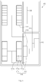
FIG. 1 is a view of a battery energy storage system according to a first embodiment of the present invention. -
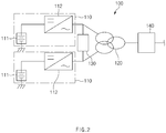
FIG. 2 is a schematic circuit view of the battery energy storage system according to the first embodiment of the present invention. -
FIG. 3 is a circuit view illustrating a state in which an abnormal operation does not occur in the battery energy storage system according to the first embodiment of the present invention. -
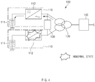
FIG. 4 is a circuit view illustrating a state in which a partial abnormal operation occurs in the battery energy storage system according to the first embodiment of the present invention. -
FIG. 5 is a circuit view illustrating a state in which an overall abnormal operation occurs in the battery energy storage system according to the first embodiment of the present invention. -
FIG. 6 is a schematic circuit view of a battery energy storage system according to a second embodiment of the present invention. -
FIG. 7 is a schematic circuit view of a battery energy storage system according to a third embodiment of the present invention. -
FIG. 8 is a circuit view illustrating a state in which an abnormal operation does not occur in the battery energy storage system according to the third embodiment of the present invention. -
FIG. 9 is a circuit view illustrating a state in which a partial abnormal operation occurs in the battery energy storage system according to the third embodiment of the present invention. - Hereinafter, embodiments of the present invention will be described in detail with reference to the accompanying drawings in such a manner that the technical idea of the present invention may easily be carried out by a person with ordinary skill in the art to which the invention pertains. The present invention may, however, be embodied in different forms and should not be construed as limited to the embodiments set forth herein. In the drawings, anything unnecessary for describing the present invention will be omitted for clarity, and also like reference numerals in the drawings denote like elements.
- As illustrated in
FIGS. 1 and2 , a batteryenergy storage system 100 according to a first embodiment of the present invention may include a plurality ofbattery boxes 111, a plurality of power converter systems (PCSs) 112, atransformer 120, and acontroller 130 so as to control selective charging or discharging of the plurality of battery packs. - The plurality of
battery boxes 111 are provided with a plurality ofbattery packs 111a, and the plurality ofbattery packs 111a are disposed to be connected to each other in series or parallel. Also, thebattery packs 111a are provided with battery cells (not shown) connected to each other in series or parallel. - Here, each of the battery boxes has a feature in which, when the plurality of
battery packs 111a are connected to each other in parallel, thebattery box 111 may increase in capacity, and when the plurality ofbattery packs 111a are connected to each other in series, the battery box may increase in voltage. Thus, due to the feature, a portion of the plurality ofbattery boxes 111 may be provided as abattery box 111 having high capacity, and the remaining battery boxes may be provided asbattery boxes 111, each of which has a high voltage (power). As a result, the battery boxes may be effectively applied to various working environments. - The plurality of
power converter systems 112 may be respectively connected to the plurality ofbattery boxes 111 to selectively charge or discharge the plurality ofbattery boxes 111 through alternating current supplied from an external power source device (not shown). Due to the above-described feature, the plurality ofpower converter systems 112 may charge all the plurality ofbattery boxes 111 and discharge all the plurality ofbattery boxes 111. Also, the plurality ofpower converter systems 112 may charge a portion of the plurality ofbattery boxes 111, discharge a portion of the plurality ofbattery boxes 111, and stop theremaining battery boxes 111 so that the charging or discharging does not occur. As a result, continuity in charging or discharging may be achieved, and various patterns with respect to the charging and discharging may be realized. - The
transformer 120 is disposed between the external power source device and the plurality ofpower converter systems 112 to change a voltage or current value of the alternating current so that the alternating current is stably supplied from the external power source device to the plurality ofpower converter systems 112. Here, a three-winding transformer may be used as thetransformer 120. The three-winding transformer may have three sets of windings to stably supply the alternating current to the plurality ofpower converter systems 112. - The
controller 130 may control the plurality ofpower converter systems 112 so that the plurality ofbattery boxes 111 are selectively charged or discharged. Thus, the plurality ofbattery boxes 111 and the plurality ofpower converter systems 112 may operate to be linked with each other or independently operate through thecontroller 130. - Particularly, when at least one of the plurality of
battery boxes 111 abnormally operates, thecontroller 130 may control the plurality ofpower converter systems 112 to stop the at least onebattery box 111, which abnormally operates, and to charge or discharge the remainingbattery boxes 111. - Also, when at least one of the plurality of
power converter systems 112 abnormally operates, thecontroller 130 may control the power converter systems, which normally operate, to selectively charge or discharge the plurality ofbattery boxes 111. - As described above, the
controller 130 may control the plurality ofpower converter systems 112 so that the plurality ofbattery boxes 111 are selectively charged or discharged, thereby achieving continuity in charging or discharging. - The
controller 130 may control the plurality ofpower converter systems 112 to charge or discharge only thebattery box 111 having the high capacity and also charge or discharge only thebattery box 111 having the high voltage (power). - The
controller 130 may check a normal or abnormal state in real time through a detecting sensor (not shown) mounted on thepower converter systems 112 or thebattery packs 111a when charging or discharging thebattery packs 111a. A temperature detecting senor or a smoke detecting sensor may be used as the detecting sensor. - The battery
energy storage system 100 having the above-described constitutions according to the first embodiment of the present invention will be described with reference to the accompanying drawings. - As illustrated in
FIG. 2 , in the battery energy storage system according to the first embodiment of the present invention, the number ofbattery boxes 111 and the number ofpower converter systems 112 are the same. Thebattery boxes 111 and thepower converter systems 112 are one-to-one correspondingly connected to each other to form a plurality of charging/dischargingdevices 110. Thecontroller 130 may control the plurality of charging/dischargingdevices 110 so that the plurality of charging/discharging devices operate to be linked with each other or independently operate. - Here, the plurality of charging/discharging
devices 110 may abnormally operate by an external impact or deterioration of the devices. That is, when thebattery boxes 111 or thepower converter systems 112 abnormally operate, thecontroller 130 may stop the charging/dischargingdevices 110 including the battery boxes or the power converter systems, which abnormally operate, and allow the remaining charging/dischargingdevices 110, which normally operate, to operate for performing the charging or discharging. - Hereinafter, the battery
energy storage system 100 according to the first embodiment of the present invention will be described in detail. - As illustrated in
FIG. 3 , when all the charging/dischargingdevices 110 normally operate, thecontroller 130 controls the charging/dischargingdevices 110 so that the plurality of charging/dischargingdevices 110 are linked with each other to perform the charging or discharging. That is to say, the charging or discharging may be performed through all the charging/dischargingdevices 110 to maximize continuity and efficiency in charging and discharging. - Particularly, since the plurality of charging/discharging
devices 110 are normal, thecontroller 130 may construct a charging/discharging system in which the plurality of charging/dischargingdevices 110 are linked with each other to perform the charging or discharging and construct a charging/discharging system in which the plurality of charging/dischargingdevices 110 independently operate to perform the charging or discharging. - As illustrated in
FIG. 4 , when one of the charging/dischargingdevices 110 abnormally operates, thecontroller 130 may stop an operation of the charging/dischargingdevice 110 including the battery box or the power converter system, which abnormally operates, and allow the charging/dischargingdevices 110, which normally operates, to independently operate for charging or discharging, thereby achieving the continuity in charging and discharging. - That is to say, the
controller 130 may stop the charging/dischargingdevice 100, which abnormally operates, to previously prevent an accident from occurring and allow the charging/dischargingdevices 110 to operate for charging or discharging and thereby to prevent the system from being stopped. - As illustrated in
FIG. 5 , when all the charging/dischargingdevices 110 abnormally operates, i.e., when all thebattery boxes 111 or thepower converter systems 112 provided in the plurality of charging/dischargingdevices 110 abnormally operate, thecontroller 130 may stop the operation of all the charging/dischargingdevices 110 to previously prevent the accident from occurring. - That is to say, since all the charging/discharging
devices 110 abnormally operate, the normal operation may be impossible. Thus, the operation of all the charging/dischargingdevices 110 may be stopped. - The
controller 130 may control amonitor device 140 to display a connection state between the plurality ofbattery boxes 111 and the plurality ofpower converter systems 112 through themonitor device 140. As a result, a worker may easily confirm the present connection state between the batteries and the power converter systems. - Particularly, when the charging/discharging
devices 110 abnormally operate, thecontroller 130 may control themonitor device 140 so that the charging/dischargingdevices 110 including thebattery boxes 111 or thepower converter systems 112, which abnormally operate, are displayed through themonitor device 140. As a result, the worker may easily confirm the charging/dischargingdevices 110, which abnormally operate. - As described above, in the battery
energy storage system 100 according to the first embodiment of the present invention, all the charging/dischargingdevices 110 or only a portion of the charging/dischargingdevices 110 may operate for charging or discharging, or all the charging/dischargingdevices 110 may be stopped and thus do not operate for charging or discharging according to whether the charging/dischargingdevices 110 normally operate or not. - Hereinafter, in description of another embodiment of the present invention, a constitution having a structure and function similar to those of the constitution according to the first embodiment have been given the same reference numeral in the drawings, and thus duplicated description will be omitted.
- As illustrated in
FIG. 6 , in a battery energy storage system 100' according to the second embodiment of the present invention, the number ofbattery boxes 111 and the number ofpower converter systems 112 are different from each other. Thus, acontroller 130 may connect onepower converter system 112 to all the plurality ofbattery boxes 111 to perform charging or discharging. That is to say, thecontroller 130 connects onepower converter system 112 and theplurality battery boxes 111 to each other in parallel. Thus, all the plurality ofbattery boxes 111 may be charged or discharged, or the plurality ofbattery boxes 111 may be individually charged or discharged through onepower converter system 112. - Hereinafter, the battery energy storage system 100' according to the second embodiment of the present invention will be described in detail.
- As illustrated in
FIG. 6 , the battery energy storage system 100' according to the second embodiment of the present invention includes at least fourbattery boxes 111 and twopower converter systems 112. As a result, thecontroller 130 may charge or discharge the two battery boxes through the twopower converter systems 112 and stop the remainingbattery boxes 111 so that the charging or discharging is not performed. Thus, the charging or discharging of the plurality ofbattery boxes 111 may be performed at the same time, or only the requiredbattery boxes 111 may be charged or discharged. As a result, thebattery boxes 111 may extend in lifespan, and the charging or discharging may be performed in various patterns. - When at least one of the plurality of
battery boxes 111 abnormally operates, thecontroller 130 may control the plurality ofpower converter systems 112 to stop the at least onebattery box 111, which abnormally operates, so that the charging or discharging is not performed and to charge or discharge thebattery boxes 111, which normally operate. Thus, the charging or discharging may be performed by using only onebattery box 111, which normally operates. As a result, the continuity in charging and discharging may be achieved. - When at least one of the
power converter systems 112 abnormally operates, thecontroller 130 may stop the at least onepower converter system 112, which abnormally operates, and control thepower converter systems 112, which normally operate, to charge or discharge the plurality ofbattery boxes 111. Thus, the plurality ofbattery boxes 111 may be charged or discharged by using only one power converter system. As a result, the continuity in charging and discharging may be achieved. - As illustrated in
FIG. 7 , a batteryenergy storage system 100" according to the third embodiment of the present invention includes onebattery box 111 provided with a plurality ofbattery packs 111a, a charging/dischargingdevice 110 provided with a plurality ofpower converter systems 112 connected to the onebattery box 111 in parallel and supplying alternating current to the onebattery box 111 to perform charging or discharging, atransformer 120 supplying the alternating current supplied from an external power source device to each of the plurality ofpower converter systems 112 provided in the charging/dischargingdevice 110, and acontroller 130 controlling the onebattery box 111 to charge or discharge the onebattery box 111 through the remainingpower converter systems 112 when onepower converter system 112 of the plurality ofpower converter systems 112 abnormally operates. - That is, in the battery
energy storage system 100" according to the third embodiment of the present invention, the plurality of power converter systems may be connected to onebattery box 111 to charge or discharge thebattery box 111 through the remainingpower converter systems 112 although onepower converter system 112 abnormally operates. - Hereinafter, the battery
energy storage system 100" according to the third embodiment of the present invention will be described in detail. - The battery
energy storage system 100" according to the third embodiment of the present invention includes a charging/dischargingdevice 110 including onebattery box 111 and twopower converter systems 112. As illustrated inFIG. 8 , thecontroller 130 may control the plurality ofpower converter systems 112 to charge or discharge thebattery box 111 when all thepower converter systems 112 normally operate. - As illustrated in
FIG. 9 , when at least one of the plurality ofpower converter systems 112 abnormally operates, thecontroller 130 may block alternating current to the at least onepower converter system 112, which abnormally operates, and charges or discharge thebattery box 111 through thepower converter systems 112, which normally operate. - When all the plurality of power converter systems abnormally operate, the
controller 130 may stop an operation of the charging/dischargingdevice 110 to prevent an accident from occurring. - Accordingly, the scope of the present invention is defined by the appended claims rather than the foregoing description and the exemplary embodiments described therein. Various modifications made within the meaning of an equivalent of the claims of the invention and within the claims are to be regarded to be in the scope of the present invention.
-
- 100:
- Battery energy storage system
- 110:
- Charging/discharging device
- 111:
- Battery box
- 111a:
- Battery pack
- 112:
- Power converter system
- 120:
- Transformer
- 130:
- Controller
Claims (16)
- A battery energy storage system comprising:a plurality of battery boxes provided with a plurality of battery packs;a plurality of power converter systems respectively connected to the plurality of battery boxes to selectively charge or discharge the plurality of battery boxes through alternating current supplied from an external power source device;a transformer disposed between the external power source device and the plurality of power converter systems; anda controller controlling the plurality of power converter systems to selectively charge or discharge the plurality of battery boxes.
- The battery energy storage system of claim 1, wherein, when the number of battery boxes and the number of power converter systems are the same, the controller connects the battery boxes and the power converter systems to one-to-one correspond to each other and thereby to form a plurality of charging/discharging devices, and
the plurality of charging/discharging devices are controlled by the controller to operate to be linked with each other or independently operate. - The battery energy storage system of claim 2, wherein, when the plurality of charging/discharging devices normally operate, the controller controls the plurality of charging/discharging devices to operate to be linked with each other and thereby to perform charging or discharging.
- The battery energy storage system of claim 2, wherein, when one of the battery boxes or the power converter systems abnormally operates, the controller stops the charging/discharging devices, which abnormally operate, so that the charging or discharging is not performed and allows the charging/discharging devices to be independently charged or discharged.
- The battery energy storage system of claim 2, wherein, when all the plurality of charging/discharging devices abnormally operate, the controller stops the plurality of charging/discharging devices so that the charging or discharging is not performed.
- The battery energy storage system of claim 1, wherein, when the number of battery boxes and the number of power converter systems are different from each other, the controller connects the power converter systems to the plurality of battery boxes to charge or discharge all the plurality of battery boxes or individually charge or discharge the plurality of battery boxes through one power converter system.
- The battery energy storage system of claim 6, wherein, when at least four battery boxes and two power converter systems are provided, the controller charges or discharges the two battery boxes through the two power converter systems and stops the remaining battery boxes so that the charging or discharging is not performed.
- The battery energy storage system of claim 6, wherein, when at least one of the plurality of battery boxes abnormally operates, the controller controls the plurality of power converter systems to stop the at least one battery box, which abnormally operates, so that the charging or discharging is not performed and to charge or discharge the battery boxes, which normally operate.
- The battery energy storage system of claim 6, wherein, when at least one of the plurality of power converter systems abnormally operates, the controller stops the at least one power converter system, which abnormally operates, and controls the power converter systems, which normally operate, to charge or discharge the plurality of battery boxes.
- The battery energy storage system of claim 1, wherein the transformer comprises a three-winding transformer.
- The battery energy storage system of claim 1, wherein the controller controls a monitor device to display a connection state between the plurality of battery boxes and the plurality of power converter systems through the monitor device.
- The battery energy storage system of claim 1, wherein at least one of the plurality of battery boxes has capacity greater than that of each of remaining battery boxes, and
each of the remaining battery boxes has power greater than that of the at least one battery box. - A battery energy storage system comprising:a charging/discharging device comprising one battery box provided with a plurality of battery packs and a plurality of power converter systems connected to the one battery box in parallel to supply alternating current to the one battery box and thereby to perform charging or discharging;a transformer supplying the alternating current supplied from an external power source device to each of the plurality of power converter systems provided in the charging/discharging device; anda controller controlling the plurality of power converter systems to allow the one battery box to be charged or discharged through remaining power converter systems when one power converter system of the plurality of power converter systems abnormally operates.
- The battery energy storage system of claim 13, wherein, when the remaining power converter systems abnormally operate, the controller controls the charging/discharging device to stop an operation of the charging/discharging device.
- The battery energy storage system of claim 13, wherein the transformer comprises a three-winding transformer.
- The battery energy storage system of claim 13, wherein the controller controls a monitor device to display the battery box or the charging/discharging device, which abnormally operates, through the monitor device.
Applications Claiming Priority (2)
| Application Number | Priority Date | Filing Date | Title |
|---|---|---|---|
| KR20160025584 | 2016-03-03 | ||
| KR1020170019535A KR101924931B1 (en) | 2016-03-03 | 2017-02-13 | Battery Energy Storage System |
Publications (2)
| Publication Number | Publication Date |
|---|---|
| EP3214724A1 true EP3214724A1 (en) | 2017-09-06 |
| EP3214724B1 EP3214724B1 (en) | 2020-04-29 |
Family
ID=58185314
Family Applications (1)
| Application Number | Title | Priority Date | Filing Date |
|---|---|---|---|
| EP17157738.0A Active EP3214724B1 (en) | 2016-03-03 | 2017-02-23 | Battery energy storage system |
Country Status (2)
| Country | Link |
|---|---|
| US (1) | US10763677B2 (en) |
| EP (1) | EP3214724B1 (en) |
Cited By (1)
| Publication number | Priority date | Publication date | Assignee | Title |
|---|---|---|---|---|
| EP4618235A4 (en) * | 2023-11-20 | 2026-04-15 | Lg Energy Solution Ltd | BATTERY CHARGING AND DISCHARGING SYSTEM AND CONTROL DEVICE FOR IT |
Families Citing this family (2)
| Publication number | Priority date | Publication date | Assignee | Title |
|---|---|---|---|---|
| JP7200747B2 (en) * | 2019-02-26 | 2023-01-10 | 株式会社デンソー | power supply |
| US12597782B2 (en) | 2021-09-30 | 2026-04-07 | Milwaukee Electric Tool Corporation | Charger including multiple adjustable power sources |
Citations (6)
| Publication number | Priority date | Publication date | Assignee | Title |
|---|---|---|---|---|
| US20050116547A1 (en) * | 2003-12-02 | 2005-06-02 | Hsin-An Lin | Uninterruptible power system with two current conversion units |
| US20130187605A1 (en) * | 2011-12-23 | 2013-07-25 | Eetrex, Inc. | Apparatus and method for active balancing of series cells and series packs in a battery system |
| US20140077595A1 (en) * | 2011-06-01 | 2014-03-20 | Hitachi, Ltd | Battery energy storage system |
| DE102013206808A1 (en) * | 2013-04-16 | 2014-10-16 | Younicos Ag | Method and device for controlling the state of charge of a battery power plant |
| EP2804286A2 (en) * | 2013-05-15 | 2014-11-19 | LG CNS Co., Ltd. | Apparatus and method with active balancing circuit and active balancing algorithm for charging and discharging secondary batteries connected in series |
| KR20150106912A (en) | 2013-03-04 | 2015-09-22 | 가부시끼가이샤 도시바 | Secondary cell system having plurality of cells, and method for distributing charge/discharge electric power |
Family Cites Families (15)
| Publication number | Priority date | Publication date | Assignee | Title |
|---|---|---|---|---|
| JP2833460B2 (en) * | 1993-12-27 | 1998-12-09 | 株式会社日立製作所 | Power system |
| WO2008041755A1 (en) | 2006-10-04 | 2008-04-10 | The Tokyo Electric Power Company, Incorporated | Ac-dc conversion device |
| KR101094055B1 (en) | 2009-12-15 | 2011-12-19 | 삼성에스디아이 주식회사 | Energy storage systems |
| CN102612792B (en) * | 2009-12-15 | 2014-08-06 | 日本碍子株式会社 | Secondary battery control device and secondary battery control method |
| JPWO2012049963A1 (en) * | 2010-10-15 | 2014-02-24 | 三洋電機株式会社 | Power supply system including storage battery |
| WO2012090473A1 (en) * | 2010-12-29 | 2012-07-05 | 川崎重工業株式会社 | Battery module charging system |
| KR101210935B1 (en) * | 2011-03-21 | 2012-12-11 | 일진전기 주식회사 | Power supply for boosting charge |
| CN103247828A (en) * | 2012-02-02 | 2013-08-14 | 凹凸电子(武汉)有限公司 | Apparatus and method for processing battery abnormity, battery system and electric equipment |
| KR101923585B1 (en) * | 2012-07-11 | 2018-11-30 | 삼성전자 주식회사 | Apparatus and method for supplying a power of terminal equipment using a battery |
| US9583794B2 (en) * | 2013-08-26 | 2017-02-28 | Dell International L.L.C. | Scalable highly available modular battery system |
| CN104426157B (en) * | 2013-09-10 | 2017-04-19 | 台达电子企业管理(上海)有限公司 | Energy storage module and energy storage device |
| US10069430B2 (en) * | 2013-11-07 | 2018-09-04 | Regents Of The University Of Minnesota | Modular converter with multilevel submodules |
| KR101538232B1 (en) | 2013-11-28 | 2015-07-20 | 주식회사 포스코아이씨티 | Battery Conditioning System and Battery Energy Storage System Including That Battery Conditioning System |
| JP6199771B2 (en) * | 2014-02-26 | 2017-09-20 | 株式会社日立製作所 | Storage system control method |
| CN203984052U (en) * | 2014-07-28 | 2014-12-03 | 微宏动力系统(湖州)有限公司 | AC-battery power source |
-
2017
- 2017-02-23 EP EP17157738.0A patent/EP3214724B1/en active Active
- 2017-03-02 US US15/447,821 patent/US10763677B2/en active Active
Patent Citations (6)
| Publication number | Priority date | Publication date | Assignee | Title |
|---|---|---|---|---|
| US20050116547A1 (en) * | 2003-12-02 | 2005-06-02 | Hsin-An Lin | Uninterruptible power system with two current conversion units |
| US20140077595A1 (en) * | 2011-06-01 | 2014-03-20 | Hitachi, Ltd | Battery energy storage system |
| US20130187605A1 (en) * | 2011-12-23 | 2013-07-25 | Eetrex, Inc. | Apparatus and method for active balancing of series cells and series packs in a battery system |
| KR20150106912A (en) | 2013-03-04 | 2015-09-22 | 가부시끼가이샤 도시바 | Secondary cell system having plurality of cells, and method for distributing charge/discharge electric power |
| DE102013206808A1 (en) * | 2013-04-16 | 2014-10-16 | Younicos Ag | Method and device for controlling the state of charge of a battery power plant |
| EP2804286A2 (en) * | 2013-05-15 | 2014-11-19 | LG CNS Co., Ltd. | Apparatus and method with active balancing circuit and active balancing algorithm for charging and discharging secondary batteries connected in series |
Cited By (1)
| Publication number | Priority date | Publication date | Assignee | Title |
|---|---|---|---|---|
| EP4618235A4 (en) * | 2023-11-20 | 2026-04-15 | Lg Energy Solution Ltd | BATTERY CHARGING AND DISCHARGING SYSTEM AND CONTROL DEVICE FOR IT |
Also Published As
| Publication number | Publication date |
|---|---|
| US10763677B2 (en) | 2020-09-01 |
| EP3214724B1 (en) | 2020-04-29 |
| US20170256964A1 (en) | 2017-09-07 |
Similar Documents
| Publication | Publication Date | Title |
|---|---|---|
| US10763682B2 (en) | Energy storage system and controlling method thereof | |
| EP3439132B1 (en) | Power supply system, control system and power control method for power supply system | |
| KR101364094B1 (en) | Battery system and energy storage system including the same | |
| JP5725183B2 (en) | Energy storage system and control method thereof | |
| KR101117706B1 (en) | Power supply apparatus | |
| CN103165947B (en) | Electric energy storage system and method of maintaining the same | |
| JP6817987B2 (en) | High-voltage battery management and balancing circuits and their applications | |
| US8384343B2 (en) | Electric accumulators having self regulated battery with integrated bi-directional power management and protection | |
| KR101541960B1 (en) | An energy storage system using high frequency link type dc-dc converter | |
| JP6159809B2 (en) | Test equipment for energy storage devices | |
| EP2632016A1 (en) | Battery pack, method for charging/discharging same, and power consumption device | |
| EP2475064A2 (en) | Battery system and energy storage system including the same | |
| JP2002135986A (en) | Voltage equalizer device and method thereof | |
| KR101587333B1 (en) | High reliabel battery energy storage system | |
| US20120228943A1 (en) | Electric power supply system | |
| US20120235491A1 (en) | Prioritization circuit and electric power supply system | |
| KR20170019971A (en) | Battery Pack and Energy Storage System Including Thereof | |
| EP3214724B1 (en) | Battery energy storage system | |
| US20170301963A1 (en) | Method and apparatus for performing string-level dynamic reconfiguration in an energy system | |
| KR101924931B1 (en) | Battery Energy Storage System | |
| KR20170026695A (en) | Hybrid energy storage system | |
| KR102061308B1 (en) | Control power supplying apparatus and method for battery management and energy stock system using the same | |
| KR101465179B1 (en) | An energy storage system using bidirectional pwm inverter | |
| KR20160007837A (en) | Battery Energy Storage System | |
| EP3270485B1 (en) | Power storage system |
Legal Events
| Date | Code | Title | Description |
|---|---|---|---|
| PUAI | Public reference made under article 153(3) epc to a published international application that has entered the european phase |
Free format text: ORIGINAL CODE: 0009012 |
|
| STAA | Information on the status of an ep patent application or granted ep patent |
Free format text: STATUS: REQUEST FOR EXAMINATION WAS MADE |
|
| 17P | Request for examination filed |
Effective date: 20170223 |
|
| AK | Designated contracting states |
Kind code of ref document: A1 Designated state(s): AL AT BE BG CH CY CZ DE DK EE ES FI FR GB GR HR HU IE IS IT LI LT LU LV MC MK MT NL NO PL PT RO RS SE SI SK SM TR |
|
| AX | Request for extension of the european patent |
Extension state: BA ME |
|
| STAA | Information on the status of an ep patent application or granted ep patent |
Free format text: STATUS: EXAMINATION IS IN PROGRESS |
|
| 17Q | First examination report despatched |
Effective date: 20180305 |
|
| GRAP | Despatch of communication of intention to grant a patent |
Free format text: ORIGINAL CODE: EPIDOSNIGR1 |
|
| STAA | Information on the status of an ep patent application or granted ep patent |
Free format text: STATUS: GRANT OF PATENT IS INTENDED |
|
| INTG | Intention to grant announced |
Effective date: 20200109 |
|
| GRAS | Grant fee paid |
Free format text: ORIGINAL CODE: EPIDOSNIGR3 |
|
| GRAA | (expected) grant |
Free format text: ORIGINAL CODE: 0009210 |
|
| STAA | Information on the status of an ep patent application or granted ep patent |
Free format text: STATUS: THE PATENT HAS BEEN GRANTED |
|
| AK | Designated contracting states |
Kind code of ref document: B1 Designated state(s): AL AT BE BG CH CY CZ DE DK EE ES FI FR GB GR HR HU IE IS IT LI LT LU LV MC MK MT NL NO PL PT RO RS SE SI SK SM TR |
|
| REG | Reference to a national code |
Ref country code: GB Ref legal event code: FG4D |
|
| REG | Reference to a national code |
Ref country code: CH Ref legal event code: EP |
|
| REG | Reference to a national code |
Ref country code: AT Ref legal event code: REF Ref document number: 1264755 Country of ref document: AT Kind code of ref document: T Effective date: 20200515 |
|
| REG | Reference to a national code |
Ref country code: DE Ref legal event code: R096 Ref document number: 602017015462 Country of ref document: DE |
|
| REG | Reference to a national code |
Ref country code: IE Ref legal event code: FG4D |
|
| REG | Reference to a national code |
Ref country code: NL Ref legal event code: MP Effective date: 20200429 |
|
| REG | Reference to a national code |
Ref country code: LT Ref legal event code: MG4D |
|
| PG25 | Lapsed in a contracting state [announced via postgrant information from national office to epo] |
Ref country code: PT Free format text: LAPSE BECAUSE OF FAILURE TO SUBMIT A TRANSLATION OF THE DESCRIPTION OR TO PAY THE FEE WITHIN THE PRESCRIBED TIME-LIMIT Effective date: 20200831 Ref country code: NO Free format text: LAPSE BECAUSE OF FAILURE TO SUBMIT A TRANSLATION OF THE DESCRIPTION OR TO PAY THE FEE WITHIN THE PRESCRIBED TIME-LIMIT Effective date: 20200729 Ref country code: IS Free format text: LAPSE BECAUSE OF FAILURE TO SUBMIT A TRANSLATION OF THE DESCRIPTION OR TO PAY THE FEE WITHIN THE PRESCRIBED TIME-LIMIT Effective date: 20200829 Ref country code: SE Free format text: LAPSE BECAUSE OF FAILURE TO SUBMIT A TRANSLATION OF THE DESCRIPTION OR TO PAY THE FEE WITHIN THE PRESCRIBED TIME-LIMIT Effective date: 20200429 Ref country code: GR Free format text: LAPSE BECAUSE OF FAILURE TO SUBMIT A TRANSLATION OF THE DESCRIPTION OR TO PAY THE FEE WITHIN THE PRESCRIBED TIME-LIMIT Effective date: 20200730 Ref country code: FI Free format text: LAPSE BECAUSE OF FAILURE TO SUBMIT A TRANSLATION OF THE DESCRIPTION OR TO PAY THE FEE WITHIN THE PRESCRIBED TIME-LIMIT Effective date: 20200429 Ref country code: LT Free format text: LAPSE BECAUSE OF FAILURE TO SUBMIT A TRANSLATION OF THE DESCRIPTION OR TO PAY THE FEE WITHIN THE PRESCRIBED TIME-LIMIT Effective date: 20200429 |
|
| REG | Reference to a national code |
Ref country code: AT Ref legal event code: MK05 Ref document number: 1264755 Country of ref document: AT Kind code of ref document: T Effective date: 20200429 |
|
| PG25 | Lapsed in a contracting state [announced via postgrant information from national office to epo] |
Ref country code: LV Free format text: LAPSE BECAUSE OF FAILURE TO SUBMIT A TRANSLATION OF THE DESCRIPTION OR TO PAY THE FEE WITHIN THE PRESCRIBED TIME-LIMIT Effective date: 20200429 Ref country code: BG Free format text: LAPSE BECAUSE OF FAILURE TO SUBMIT A TRANSLATION OF THE DESCRIPTION OR TO PAY THE FEE WITHIN THE PRESCRIBED TIME-LIMIT Effective date: 20200729 Ref country code: RS Free format text: LAPSE BECAUSE OF FAILURE TO SUBMIT A TRANSLATION OF THE DESCRIPTION OR TO PAY THE FEE WITHIN THE PRESCRIBED TIME-LIMIT Effective date: 20200429 Ref country code: HR Free format text: LAPSE BECAUSE OF FAILURE TO SUBMIT A TRANSLATION OF THE DESCRIPTION OR TO PAY THE FEE WITHIN THE PRESCRIBED TIME-LIMIT Effective date: 20200429 |
|
| PG25 | Lapsed in a contracting state [announced via postgrant information from national office to epo] |
Ref country code: NL Free format text: LAPSE BECAUSE OF FAILURE TO SUBMIT A TRANSLATION OF THE DESCRIPTION OR TO PAY THE FEE WITHIN THE PRESCRIBED TIME-LIMIT Effective date: 20200429 Ref country code: AL Free format text: LAPSE BECAUSE OF FAILURE TO SUBMIT A TRANSLATION OF THE DESCRIPTION OR TO PAY THE FEE WITHIN THE PRESCRIBED TIME-LIMIT Effective date: 20200429 |
|
| PG25 | Lapsed in a contracting state [announced via postgrant information from national office to epo] |
Ref country code: DK Free format text: LAPSE BECAUSE OF FAILURE TO SUBMIT A TRANSLATION OF THE DESCRIPTION OR TO PAY THE FEE WITHIN THE PRESCRIBED TIME-LIMIT Effective date: 20200429 Ref country code: SM Free format text: LAPSE BECAUSE OF FAILURE TO SUBMIT A TRANSLATION OF THE DESCRIPTION OR TO PAY THE FEE WITHIN THE PRESCRIBED TIME-LIMIT Effective date: 20200429 Ref country code: EE Free format text: LAPSE BECAUSE OF FAILURE TO SUBMIT A TRANSLATION OF THE DESCRIPTION OR TO PAY THE FEE WITHIN THE PRESCRIBED TIME-LIMIT Effective date: 20200429 Ref country code: CZ Free format text: LAPSE BECAUSE OF FAILURE TO SUBMIT A TRANSLATION OF THE DESCRIPTION OR TO PAY THE FEE WITHIN THE PRESCRIBED TIME-LIMIT Effective date: 20200429 Ref country code: AT Free format text: LAPSE BECAUSE OF FAILURE TO SUBMIT A TRANSLATION OF THE DESCRIPTION OR TO PAY THE FEE WITHIN THE PRESCRIBED TIME-LIMIT Effective date: 20200429 Ref country code: IT Free format text: LAPSE BECAUSE OF FAILURE TO SUBMIT A TRANSLATION OF THE DESCRIPTION OR TO PAY THE FEE WITHIN THE PRESCRIBED TIME-LIMIT Effective date: 20200429 Ref country code: RO Free format text: LAPSE BECAUSE OF FAILURE TO SUBMIT A TRANSLATION OF THE DESCRIPTION OR TO PAY THE FEE WITHIN THE PRESCRIBED TIME-LIMIT Effective date: 20200429 Ref country code: ES Free format text: LAPSE BECAUSE OF FAILURE TO SUBMIT A TRANSLATION OF THE DESCRIPTION OR TO PAY THE FEE WITHIN THE PRESCRIBED TIME-LIMIT Effective date: 20200429 |
|
| REG | Reference to a national code |
Ref country code: DE Ref legal event code: R097 Ref document number: 602017015462 Country of ref document: DE |
|
| PG25 | Lapsed in a contracting state [announced via postgrant information from national office to epo] |
Ref country code: PL Free format text: LAPSE BECAUSE OF FAILURE TO SUBMIT A TRANSLATION OF THE DESCRIPTION OR TO PAY THE FEE WITHIN THE PRESCRIBED TIME-LIMIT Effective date: 20200429 Ref country code: SK Free format text: LAPSE BECAUSE OF FAILURE TO SUBMIT A TRANSLATION OF THE DESCRIPTION OR TO PAY THE FEE WITHIN THE PRESCRIBED TIME-LIMIT Effective date: 20200429 |
|
| PLBE | No opposition filed within time limit |
Free format text: ORIGINAL CODE: 0009261 |
|
| STAA | Information on the status of an ep patent application or granted ep patent |
Free format text: STATUS: NO OPPOSITION FILED WITHIN TIME LIMIT |
|
| 26N | No opposition filed |
Effective date: 20210201 |
|
| PG25 | Lapsed in a contracting state [announced via postgrant information from national office to epo] |
Ref country code: SI Free format text: LAPSE BECAUSE OF FAILURE TO SUBMIT A TRANSLATION OF THE DESCRIPTION OR TO PAY THE FEE WITHIN THE PRESCRIBED TIME-LIMIT Effective date: 20200429 |
|
| PG25 | Lapsed in a contracting state [announced via postgrant information from national office to epo] |
Ref country code: MC Free format text: LAPSE BECAUSE OF FAILURE TO SUBMIT A TRANSLATION OF THE DESCRIPTION OR TO PAY THE FEE WITHIN THE PRESCRIBED TIME-LIMIT Effective date: 20200429 |
|
| REG | Reference to a national code |
Ref country code: BE Ref legal event code: MM Effective date: 20210228 |
|
| PG25 | Lapsed in a contracting state [announced via postgrant information from national office to epo] |
Ref country code: LI Free format text: LAPSE BECAUSE OF NON-PAYMENT OF DUE FEES Effective date: 20210228 Ref country code: LU Free format text: LAPSE BECAUSE OF NON-PAYMENT OF DUE FEES Effective date: 20210223 Ref country code: CH Free format text: LAPSE BECAUSE OF NON-PAYMENT OF DUE FEES Effective date: 20210228 |
|
| PG25 | Lapsed in a contracting state [announced via postgrant information from national office to epo] |
Ref country code: IE Free format text: LAPSE BECAUSE OF NON-PAYMENT OF DUE FEES Effective date: 20210223 |
|
| PG25 | Lapsed in a contracting state [announced via postgrant information from national office to epo] |
Ref country code: BE Free format text: LAPSE BECAUSE OF NON-PAYMENT OF DUE FEES Effective date: 20210228 |
|
| REG | Reference to a national code |
Ref country code: DE Ref legal event code: R081 Ref document number: 602017015462 Country of ref document: DE Owner name: LG ENERGY SOLUTION, LTD., KR Free format text: FORMER OWNER: LG CHEM, LTD., SEOUL, KR |
|
| PG25 | Lapsed in a contracting state [announced via postgrant information from national office to epo] |
Ref country code: HU Free format text: LAPSE BECAUSE OF FAILURE TO SUBMIT A TRANSLATION OF THE DESCRIPTION OR TO PAY THE FEE WITHIN THE PRESCRIBED TIME-LIMIT; INVALID AB INITIO Effective date: 20170223 |
|
| P01 | Opt-out of the competence of the unified patent court (upc) registered |
Effective date: 20230512 |
|
| PG25 | Lapsed in a contracting state [announced via postgrant information from national office to epo] |
Ref country code: CY Free format text: LAPSE BECAUSE OF FAILURE TO SUBMIT A TRANSLATION OF THE DESCRIPTION OR TO PAY THE FEE WITHIN THE PRESCRIBED TIME-LIMIT Effective date: 20200429 |
|
| REG | Reference to a national code |
Ref country code: GB Ref legal event code: 732E Free format text: REGISTERED BETWEEN 20230824 AND 20230831 |
|
| PG25 | Lapsed in a contracting state [announced via postgrant information from national office to epo] |
Ref country code: MK Free format text: LAPSE BECAUSE OF FAILURE TO SUBMIT A TRANSLATION OF THE DESCRIPTION OR TO PAY THE FEE WITHIN THE PRESCRIBED TIME-LIMIT Effective date: 20200429 |
|
| PG25 | Lapsed in a contracting state [announced via postgrant information from national office to epo] |
Ref country code: MT Free format text: LAPSE BECAUSE OF FAILURE TO SUBMIT A TRANSLATION OF THE DESCRIPTION OR TO PAY THE FEE WITHIN THE PRESCRIBED TIME-LIMIT Effective date: 20200429 |
|
| PG25 | Lapsed in a contracting state [announced via postgrant information from national office to epo] |
Ref country code: TR Free format text: LAPSE BECAUSE OF FAILURE TO SUBMIT A TRANSLATION OF THE DESCRIPTION OR TO PAY THE FEE WITHIN THE PRESCRIBED TIME-LIMIT Effective date: 20200429 |
|
| PGFP | Annual fee paid to national office [announced via postgrant information from national office to epo] |
Ref country code: GB Payment date: 20260122 Year of fee payment: 10 |
|
| PGFP | Annual fee paid to national office [announced via postgrant information from national office to epo] |
Ref country code: DE Payment date: 20260120 Year of fee payment: 10 |
|
| PGFP | Annual fee paid to national office [announced via postgrant information from national office to epo] |
Ref country code: FR Payment date: 20260121 Year of fee payment: 10 |