EP3214575A1 - Biological image processing device, biological image processing method, and biological image processing program - Google Patents
Biological image processing device, biological image processing method, and biological image processing program Download PDFInfo
- Publication number
- EP3214575A1 EP3214575A1 EP17155367.0A EP17155367A EP3214575A1 EP 3214575 A1 EP3214575 A1 EP 3214575A1 EP 17155367 A EP17155367 A EP 17155367A EP 3214575 A1 EP3214575 A1 EP 3214575A1
- Authority
- EP
- European Patent Office
- Prior art keywords
- local
- orientation
- palm
- pixels
- orientations
- Prior art date
- Legal status (The legal status is an assumption and is not a legal conclusion. Google has not performed a legal analysis and makes no representation as to the accuracy of the status listed.)
- Granted
Links
Images




Classifications
-
- G—PHYSICS
- G06—COMPUTING OR CALCULATING; COUNTING
- G06V—IMAGE OR VIDEO RECOGNITION OR UNDERSTANDING
- G06V40/00—Recognition of biometric, human-related or animal-related patterns in image or video data
- G06V40/10—Human or animal bodies, e.g. vehicle occupants or pedestrians; Body parts, e.g. hands
- G06V40/12—Fingerprints or palmprints
-
- G—PHYSICS
- G06—COMPUTING OR CALCULATING; COUNTING
- G06T—IMAGE DATA PROCESSING OR GENERATION, IN GENERAL
- G06T7/00—Image analysis
- G06T7/10—Segmentation; Edge detection
- G06T7/12—Edge-based segmentation
-
- G—PHYSICS
- G06—COMPUTING OR CALCULATING; COUNTING
- G06T—IMAGE DATA PROCESSING OR GENERATION, IN GENERAL
- G06T7/00—Image analysis
- G06T7/70—Determining position or orientation of objects or cameras
- G06T7/73—Determining position or orientation of objects or cameras using feature-based methods
-
- G—PHYSICS
- G06—COMPUTING OR CALCULATING; COUNTING
- G06T—IMAGE DATA PROCESSING OR GENERATION, IN GENERAL
- G06T7/00—Image analysis
- G06T7/70—Determining position or orientation of objects or cameras
- G06T7/77—Determining position or orientation of objects or cameras using statistical methods
-
- G—PHYSICS
- G06—COMPUTING OR CALCULATING; COUNTING
- G06V—IMAGE OR VIDEO RECOGNITION OR UNDERSTANDING
- G06V10/00—Arrangements for image or video recognition or understanding
- G06V10/20—Image preprocessing
- G06V10/24—Aligning, centring, orientation detection or correction of the image
- G06V10/242—Aligning, centring, orientation detection or correction of the image by image rotation, e.g. by 90 degrees
-
- G—PHYSICS
- G06—COMPUTING OR CALCULATING; COUNTING
- G06V—IMAGE OR VIDEO RECOGNITION OR UNDERSTANDING
- G06V40/00—Recognition of biometric, human-related or animal-related patterns in image or video data
- G06V40/10—Human or animal bodies, e.g. vehicle occupants or pedestrians; Body parts, e.g. hands
- G06V40/12—Fingerprints or palmprints
- G06V40/1347—Preprocessing; Feature extraction
-
- G—PHYSICS
- G06—COMPUTING OR CALCULATING; COUNTING
- G06T—IMAGE DATA PROCESSING OR GENERATION, IN GENERAL
- G06T2207/00—Indexing scheme for image analysis or image enhancement
- G06T2207/30—Subject of image; Context of image processing
- G06T2207/30196—Human being; Person
Definitions
- a certain aspect of embodiments described herein relates to a biological image processing device, a biological image processing method, and a biological image processing program.
- Patent Document 1 Japanese Laid-Open Patent Publication No. 2009-003492
- the present invention has been made in view of those circumstances, and an object thereof is to provide a biological image processing device, a biological image processing method, and a biological image processing program that are capable of achieving high authentication accuracy at low costs.
- a biological image processing device including: a line extracting unit configured to extract at least one line from contours of a palm and principal lines of the palm shown in an image of the palm; a pixel extracting unit configured to extract pixels of the line extracted by the line extracting unit; a local region setting unit configured to set a local region for each of the pixels, each local region including each corresponding one of the pixels; a local orientation calculating unit configured to calculate, for each local region, local orientations of the line extracted by the line extracting unit, in accordance with gradient intensities related to respective orientations of each corresponding local region; and an orientation calculating unit configured to calculate an orientation of the palm in accordance with a statistical amount of the respective local orientations.
- FIG. 1A is a block diagram for explaining the hardware configuration of a biometric authentication device 100 according to a first embodiment.
- FIG. 1B is a schematic view of a biological object sensor 105, which will be described later.
- the biometric authentication device 100 includes a CPU 101, a RAM 102, a storage device 103, a display device 104, the biological object sensor 105, a communication unit 106, and an attribute information acquiring unit 107. These components are connected by a bus or the like.
- the CPU (Central Processing Unit) 101 is a central processor.
- the CPU 101 includes one or more cores.
- the RAM (Random Access Memory) 102 is a volatile memory that temporarily stores a program to be executed by the CPU 101, data to be processed by the CPU 101, and the like.
- the storage device 103 is a nonvolatile storage.
- a read only memory (ROM), a solid-state drive (SSD) such as a flash memory, a hard disk to be driven by a hard disk drive, or the like can be used as the storage device 103.
- a biometric authentication program according to this embodiment is stored in the storage device 103.
- the display device 104 is a liquid crystal display, an electroluminescence panel, or the like, and displays the results of the later described processes and the like.
- the biological object sensor 105 is a sensor that acquires biological information about a user, and acquires an image of the palm of the user's hand in a non-contact manner in this embodiment.
- the biological object sensor 105 is a complementary metal oxide semiconductor (CMOS) camera, or the like.
- CMOS complementary metal oxide semiconductor
- the biological object sensor 105 can acquire a palm pattern, the contours of the palm, the principal lines of the palm, and the like, in accordance with visible light information, for example.
- the principal lines of the palm include the line of Heart, the line of Head, and the line of Life.
- the biological object sensor 105 can also acquire vein patterns, using near infrared rays.
- an image of the palm is preferably an image of the entire palm including the finger tips, only the palm and the base portions of the fingers may be included in an image of the palm.
- the communication unit 106 is a connection interface to a local area network (LAN), for example.
- the attribute information acquiring unit 107 is an input device such as a keyboard and a mouse, and is a device for inputting the ID, the username, the password, and the like for identifying the user, for example.
- the biometric authentication program stored in the storage device 103 is loaded into the RAM 102 so that the program can be executed.
- the CPU 101 executes the biometric authentication program loaded into the RAM 102.
- the respective processes are carried out by the biometric authentication device 100.
- the registration process is a process of registering biological features obtained from palm images acquired by the biological object sensor 105 in a database, associating the biological features with the respective users.
- palm prints, vein patterns, palm shapes, or the like extracted from palm images are registered as the biological features in the database.
- the authentication process is a process of checking a verification biological feature acquired by the biological object sensor 105 against the corresponding biological feature registered in the database. In this embodiment, if the degree of similarity between a vein pattern acquired during the authentication process and a vein pattern registered in the database is equal to or higher than a threshold value, the user is determined to be a registered user.
- the registration process and the authentication process will be described later in detail.
- FIG. 2 is a block diagram showing the respective functions to be achieved through execution of the biometric authentication program.
- a correcting unit 10 As the biometric authentication program is executed, a correcting unit 10, a biological feature extracting unit 20, a registering unit 30, an authenticating unit 40, a database 50, and the like are formed.
- the correcting unit 10 has the functions of a biological image processing device. Therefore, of the biological authentication program, the program for forming the correcting unit 10 has the functions of a biological image processing program.
- the correcting unit 10 includes a biological curve detecting unit 11, a pixel extracting unit 12, a local region setting unit 13, a local orientation calculating unit 14, a mean orientation calculating unit 15, a correction angle calculating unit 16, and a corrected image acquiring unit 17. The example shown in FIGs.
- 1 and 2 is formed with a stand-alone terminal, but does not necessarily involve such a stand-alone terminal.
- this embodiment can also be applied to a client server system.
- client server system For ease of explanation, an example with a stand-along terminal is described in this embodiment.
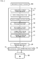
- FIG. 3 is a flowchart showing an example of the registration process in detail. Referring to FIGs. 2 and 3 , the registration process is described below.
- the attribute information acquiring unit 107 acquires attribution information about a user (step S1).
- the biological object sensor 105 acquires a palm image of the user putting a hand above the biological object sensor 105 (step S2).
- the biological curve detecting unit 11 detects biological curves as edges from the palm image acquired by the biological object sensor 105, according to a known edge detection method, such as Sobel filtering or Laplacian filtering (step S3).
- the contours of the palm and the principal lines of the palm are referred to as biological curves
- the pixels constituting the biological curves are referred to as biological curve pixels.
- FIG. 4 shows an example of biological curves.
- the right and left contours, the line of Heart, the line of Head, and the line of Life are shown as an example of biological curves.
- only one biological curve may be used, or two or more biological curves may be used.
- the number and the types of the biological curves to be used are the same between the registration process and the authentication process.
- the local orientation calculating unit 14 calculates the local orientation of the biological curve of each pixel among the pixels constituting a biological curve (step S4).
- the pixel extracting unit 12 extracts the biological curve pixels from the biological curve extracted by the biological curve detecting unit 11.
- the local region setting unit 13 sets a biological curve local region for each biological curve pixel.
- the biological curve local region is a smaller region than the palm image, with the biological curve pixel being the center.
- the biological curve local region may be a rectangle region of i ⁇ j pixels, with the biological curve pixel being the center.
- the biological curve local region may be a circular region having a radius of r pixels, with the biological curve pixel being the center.
- the contour of the little finger side of the palm is used as an example of the biological curve.
- the number of biological curve pixels and the number of biological curve local regions are represented by N.
- Each biological curve local region is a rectangle of 7 ⁇ 7 pixels, with the corresponding biological curve pixel being the center.
- the local orientation calculating unit 14 calculates local gradient intensities in predetermined directions ⁇ for each biological curve local region.
- angles are set so that the upward vertical direction in the image is 0 degrees, and a counterclockwise direction is a positive direction.
- a differential filter of the respective directions ⁇ shown below in the mathematical formula (1) is applied to the palm image, and the total sums of the absolute values of ⁇ -direction differential filter responses in the biological curve local region are set as the local gradient intensities Gk(x, y) in the directions ⁇ in the biological curve local region.
- the local orientation calculating unit 14 then obtains a biological curve vector indicating the orientation of the biological curve pixel of the biological curve, from the local gradient intensities in the four directions in each biological curve local region.
- the mathematical formula (2) shown below represents local gradient intensities as vectors in which the directions are ⁇ , and the size is Gk(x, y). Accordingly, the total sum of the vectors of these four directions is the vector indicating the orientation of the edge of the biological curve.
- the vector is then rotated 90 degrees, so that a biological curve orientation vector can be obtained. That is, ⁇ (x, y) + 90 degrees represents the biological curve local orientation.
- a biological curve orientation vector is calculated from a vector having an angle of a value twice greater than ⁇ , and the orientation obtained by adding 90 degrees to half the angle formed by the biological curve orientation vector is set as the local orientation of the biological curve.
- the mean orientation calculating unit 15 calculates the mean orientation ⁇ of the biological curve from the statistical amount of N local orientations calculated from N biological curve local regions (step S5). For example, the mean orientation calculating unit 15 calculates the mean value or the median value of N values as the mean orientation. In a case where two or more biological curves are used, the mean orientations of the respective biological curves are calculated, and are set as ⁇ 1, ⁇ 2, ..., respectively.
- FIG. 5 is a diagram showing an example of the mean orientations of respective biological curves.
- FIG. 5 shows the mean orientation ⁇ L of the contour of the little finger side (left side), the mean orientation ⁇ R of the contour of the thumb side (right side), and the mean orientation of these orientations.
- the correction angle calculating unit 16 then calculates a rotation correction angle from the mean direction calculated from the respective biological curves (step S6).
- the value obtained by multiplying the mean direction by -1 is set as the rotation correction angle.
- the value obtained by multiplying the mean value of the mean orientations ⁇ 1, ⁇ 2, ... by -1 is set as the rotation correction angle.
- the corrected image acquiring unit 17 then rotates the palm image by the rotation correction angle, to create a corrected image (step S7).
- the center of rotation is the center of the palm image, or is the center of the gravity coordinates of an image that has the foreground region of the palm image as 1 and the background region as 0.
- FIG. 6 shows an example of rotation correction in a case where the right and left contours of the palm are used as the biological curves. Since the mean orientation of the two biological curves is represented by ⁇ mean, the rotation correction angle is - ⁇ mean, and an image obtained by rotating the biological image by - ⁇ mean about the image center O is obtained as the corrected image.
- the biological feature extracting unit 20 then extracts a biological feature from the corrected image (step S8).
- the biological feature is the vein pattern, the palm print, the shape of the palm, or the like.
- the vein pattern includes the coordinates and the orientations of the end points and the branch points of the veins, joint information about two branch points, and the like.
- the registering unit 30 then associates the biological feature extracted in step S8 with the attribute information acquired in step S1, and registers the attribute information and the biological feature in the database 50 (step S9).
- the biological feature registered in step S9 is referred to as a registered biological feature. Through the above procedures, the registration process is completed.
- FIG. 7 is a flowchart showing an example of the authentication process in detail.
- steps S11 through S18 are the same as steps S1 through S8 in FIG. 3 .
- the biological feature obtained in step S18 is referred to as a verification biological feature.
- the authenticating unit 40 reads, from the database 50, the registered biological feature associated with the same attribute information as that acquired in step S11, and checks the verification biological feature against the registered biological feature (step S19). Specifically, the authenticating unit 40 determines whether the degree of similarity between the registered biological feature and the verification biological feature is not lower than a threshold value, and outputs the result of the determination.
- the orientation of a biological curve is determined through calculation related to the pixels constituting the biological curve, so that the size of a positional shift due to rotation of a palm image.
- a rotation angle correction can be obtained at a low computational cost.
- local orientations are turned into a vector and are thus combined in calculating the biological curve. Accordingly, a very small difference in angle can be expressed, and the accuracy of rotation angle calculation becomes higher. Consequently, an image that achieves a high authentication accuracy can be obtained.
- the local orientations of the respective pixels constituting the biological curve are calculated, and the rotation angle of the palm image is calculated from the statistical amount of the calculated local orientations. Even if noise appears in part of the biological curve, the noise can be absorbed. Thus, a robust correction angle calculation can be performed.
- the local orientation calculating unit 14 calculates the local orientations of a biological curve, using Gabor filters.
- the Gabor filter is expressed by the mathematical formula (3) shown below.
- a filter response amplifies. This can be used in calculating the local orientation of each biological curve pixel as described below.
- x' xcos ⁇ + ysin ⁇
- y' -xsin ⁇ + ycos ⁇ .
- the contour of the little finger side of the palm is used as an example of the biological curve.
- the number of biological curve pixels and the number of biological curve local regions are N.
- Each biological curve local region is a rectangle of 7 ⁇ 7 pixels, with the corresponding biological curve pixel being the center.
- the upward vertical direction in the image is 0 degrees
- the horizontal directions are ⁇ 90 degrees.
- x and y represent the coordinates of the pixel
- ⁇ represents the wavelength of the filter
- ⁇ represents the orientation of the filter
- ⁇ represents the size of the Gaussian variance.
- ⁇ and ⁇ are the mean width of the biological curve
- the local orientation calculating unit 14 determines filter responses Gk(x, y, i, j) of the eight directions according to the above mathematical formula (3), and calculates Gk(x, y) by adding up Gk(x, y, i, j) of 7 ⁇ 7 or 49 pixels.
- the local orientation calculating unit 14 then calculates ⁇ (x, y) of each biological curve pixel (x, y) according to the mathematical formula (2) of the first embodiment, with t being 8.
- Gk(x, y) represents the intensity of the edge in each direction
- the total sum of the vectors that have the direction ⁇ and the size Gk(x, y) is calculated, so that the biological curve vector indicating the local orientations of the biological curve can be obtained. That is, ⁇ (x, y) indicates the orientation of the biological curve vector.
- the process to be performed thereafter is the same as that in the first embodiment, with the biological curve local orientation being ⁇ (x, y).
- Gabor filter responses are calculated with respect to the pixels constituting a biological curve of a palm image, and thus, rotation angle correction can be performed at a low computational cost.
- a Gabor filter has discrete orientations, filter responses are turned into a vector and are combined, so that a very small difference in angle between local orientations of the respective pixels constituting the biological curve can be expressed, and the accuracy of rotation angle calculation becomes higher. Thus, an image that achieves a high authentication accuracy can be obtained.
- the local orientation calculating unit 14 calculates local orientations of a biological curve, using orientation concentration ratios IR.
- An orientation concentration ratio IR(x, y) is expressed by the mathematical formula (4) shown below, and is calculated for each biological curve pixel.
- Hypot a b a 2 + b 2 .
- IR is closer to 1 when the variance of the local gradient intensity in the biological curve local region is larger, and is closer to 0 when the variance is smaller.
- a threshold value Th_IR for orientation concentration rates is set.
- a biological curve pixel (x, y) that satisfies IR(x, y) ⁇ Th_IR is a valid pixel
- a biological curve pixel (x, y) that satisfies IR(x, y) ⁇ Th_IR is an invalid pixel.
- the local orientation calculating unit 14 then calculates the mean value or the median value of the local orientations of the valid pixels, and sets the calculated value as the mean orientation ⁇ of the biological curve.
- the process to be performed thereafter is the same as that in the first embodiment.
- the orientation of a biological curve is determined through calculation related to the pixels constituting the biological curve, and thus, rotation angle correction can be performed at a low computational cost. Also, local orientations are turned into a vector and are combined in calculating the biological curve. With this, a very small difference in angle can be expressed, and the accuracy of rotation angle calculation can be increased. Accordingly, an image that achieves a high authentication accuracy can be obtained. In a case where noise that is an edge component not in the curve orientation appears in the biological curve, and the biological curve includes an unclear region, the pixels causing the noise are regarded as invalid pixels and are not used in calculating the biological curve orientation. Thus, the biological curve orientation can be calculated without any influence of noise, and robust rotation correction can be performed.
- FIG. 8 is a block diagram showing the respective functions to be obtained through execution of a biological authentication program according to a third embodiment.
- the configuration of the biometric authentication device is the same as that shown in FIG. 1 .
- the correcting unit 10 further includes a mean orientation correcting unit 18.
- FIG. 9 is a flowchart showing an example process to be performed in place of steps S1 through S7 of FIG. 3 and steps S11 through S17 of FIG. 7 .
- steps S21 through S26 are the same as steps S1 through S6 of FIG. 3 and steps S11 through S16 of FIG. 7 .
- the mean orientation correcting unit 18 calculates a corrected rotation correction angle from the local orientations of the biological curve and the mean orientation of these local orientations (step S27).
- the corrected image acquiring unit 17 rotates the biological image by the rotation correction angle, to acquire a corrected image (step S28).
- the mean orientation correcting unit 18 determines valid pixels that are some of biological curve pixels (x, y) having local orientations ⁇ (x, y) calculated by the local orientation calculating unit 14. The angle differences between the local orientations ⁇ (x, y) of the valid pixels and the mean orientation ⁇ of the biological curve calculated by the mean orientation calculating unit 15 are equal to or smaller than a predetermined threshold value. The mean orientation correcting unit 18 also determines invalid pixels. The angle differences between the local orientations ⁇ (x, y) of the invalid pixels and the mean orientation ⁇ of the biological curve are larger than the predetermined threshold value.
- the angle difference between the mean orientation ⁇ and a local orientation ⁇ (x, y), and the predetermined threshold value are cos( ⁇ - cp(x, y)) and cos( ⁇ /8), respectively, for example.
- the mean orientation correcting unit 18 then calculates the mean value or the median value of the orientation directions of the valid pixels among the biological curve pixels, and sets the calculated value as a corrected biological curve mean orientation ⁇ '. That is, a rotation correction angle is determined.
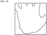
- FIG. 10 is a diagram showing an example of irregular noise.
- FIG. 11 is a diagram showing an example of the biological curve from which the irregular noise has been removed.
- Such irregular noise might appear in a case where an object other than a palm exists in the background region. Even in such a case, the local orientation of the portion of the biological curve at which the irregular noise has appeared greatly deviates from the mean orientation. Thus, only the irregular portion can be removed as shown in FIG. 11 , and the influence of noise can be further reduced.
- the orientation of a biological curve is determined through calculation related to the pixels constituting the biological curve, and thus, rotation angle correction can be performed at a low computational cost. Also, local orientations are turned into a vector and are combined in calculating the biological curve. With this, a very small difference in angle can be expressed, and the accuracy of rotation angle calculation can be increased. Accordingly, an image that achieves a high authentication accuracy can be obtained. In a case where an irregular portion appears in a biological curve, pixels having large angle differences between the mean orientation ⁇ and the local orientations ⁇ (x, y) are regarded as invalid pixels, and these invalid pixels are not used in calculating the biological curve orientation. Thus, the biological curve orientation can be calculated without any influence of irregular noise appearing in the biological curve, and robust rotation correction can be performed.
- the biological curve detecting unit 11 functions as an example of the line extracting unit that extracts at least one line from the contours of a palm and the principal lines of the palm in an image of the palm.
- the pixel extracting unit 12 functions as an example of the pixel extracting unit that extracts the pixels of the line extracted by the line extracting unit.
- the local region setting unit 13 functions as an example of the local region setting unit that sets a local region including each corresponding one of the pixels.
- the local orientation calculating unit 14 functions as an example of the local orientation calculating unit that calculates local orientations of the line extracted by the line extracting unit, in accordance with the gradient intensities of each corresponding one of the local regions.
- the mean orientation calculating unit 15 functions as an example of the orientation calculating unit that calculates the orientation of the palm from the statistical amount of the respective local orientations.
Landscapes
- Engineering & Computer Science (AREA)
- Physics & Mathematics (AREA)
- Theoretical Computer Science (AREA)
- General Physics & Mathematics (AREA)
- Multimedia (AREA)
- Computer Vision & Pattern Recognition (AREA)
- Human Computer Interaction (AREA)
- Bioinformatics & Cheminformatics (AREA)
- Life Sciences & Earth Sciences (AREA)
- Bioinformatics & Computational Biology (AREA)
- Evolutionary Biology (AREA)
- Probability & Statistics with Applications (AREA)
- Collating Specific Patterns (AREA)
- Measurement Of The Respiration, Hearing Ability, Form, And Blood Characteristics Of Living Organisms (AREA)
- Image Analysis (AREA)
- Computer Security & Cryptography (AREA)
- Computer Hardware Design (AREA)
- Software Systems (AREA)
- General Engineering & Computer Science (AREA)
Abstract
Description
- A certain aspect of embodiments described herein relates to a biological image processing device, a biological image processing method, and a biological image processing program.
- To reduce influence of a positional shift in the yaw direction, either a registered image or a verification image is rotated little by little in the yaw direction, and verification scores at all the angles are calculated. The combination having the highest score is then employed in correcting a shift in the yaw rotation (see
Patent Document 1, for example).
Patent Document 1: Japanese Laid-Open Patent Publication No.2009-003492 - However, while the authentication accuracy is increased by the setting of rotation angles at smaller intervals, a larger number of images need to be checked, resulting in higher computational costs.
- The present invention has been made in view of those circumstances, and an object thereof is to provide a biological image processing device, a biological image processing method, and a biological image processing program that are capable of achieving high authentication accuracy at low costs.
- According to an aspect of the present invention, there is provided a biological image processing device including: a line extracting unit configured to extract at least one line from contours of a palm and principal lines of the palm shown in an image of the palm; a pixel extracting unit configured to extract pixels of the line extracted by the line extracting unit; a local region setting unit configured to set a local region for each of the pixels, each local region including each corresponding one of the pixels; a local orientation calculating unit configured to calculate, for each local region, local orientations of the line extracted by the line extracting unit, in accordance with gradient intensities related to respective orientations of each corresponding local region; and an orientation calculating unit configured to calculate an orientation of the palm in accordance with a statistical amount of the respective local orientations.
-
-
FIG. 1A is a block diagram for explaining the hardware configuration of a biometric authentication device according to a first embodiment; -
FIG. 1B is a schematic view of a biological object sensor; -
FIG. 2 is a block diagram showing the respective functions to be achieved through execution of a biometric authentication program; -
FIG. 3 is a flowchart showing an example of a registration process in detail; -
FIG. 4 is a diagram showing an example of a registration process in detail; -
FIG. 5 is a diagram showing an example of the mean orientation of each biological curve; -
FIG. 6 is a diagram showing an example of rotation correction; -
FIG. 7 is a flowchart showing an example of an authentication process in detail; -
FIG. 8 is a block diagram showing the respective functions according to a third embodiment; -
FIG. 9 shows an example of a flowchart; -
FIG. 10 is a diagram showing an example of irregular noise; and -
FIG. 11 is a diagram showing an example of a biological curve from which irregular noise has been removed. - The following is a description of embodiments, with reference to the drawings.
-
FIG. 1A is a block diagram for explaining the hardware configuration of abiometric authentication device 100 according to a first embodiment.FIG. 1B is a schematic view of abiological object sensor 105, which will be described later. As shown inFIG. 1A , thebiometric authentication device 100 includes aCPU 101, aRAM 102, astorage device 103, adisplay device 104, thebiological object sensor 105, acommunication unit 106, and an attributeinformation acquiring unit 107. These components are connected by a bus or the like. - The CPU (Central Processing Unit) 101 is a central processor. The
CPU 101 includes one or more cores. The RAM (Random Access Memory) 102 is a volatile memory that temporarily stores a program to be executed by theCPU 101, data to be processed by theCPU 101, and the like. - The
storage device 103 is a nonvolatile storage. For example, a read only memory (ROM), a solid-state drive (SSD) such as a flash memory, a hard disk to be driven by a hard disk drive, or the like can be used as thestorage device 103. A biometric authentication program according to this embodiment is stored in thestorage device 103. Thedisplay device 104 is a liquid crystal display, an electroluminescence panel, or the like, and displays the results of the later described processes and the like. - The
biological object sensor 105 is a sensor that acquires biological information about a user, and acquires an image of the palm of the user's hand in a non-contact manner in this embodiment. As shown in the example inFIG. 1B , thebiological object sensor 105 is a complementary metal oxide semiconductor (CMOS) camera, or the like. Thebiological object sensor 105 can acquire a palm pattern, the contours of the palm, the principal lines of the palm, and the like, in accordance with visible light information, for example. The principal lines of the palm include the line of Heart, the line of Head, and the line of Life. Thebiological object sensor 105 can also acquire vein patterns, using near infrared rays. Although an image of the palm is preferably an image of the entire palm including the finger tips, only the palm and the base portions of the fingers may be included in an image of the palm. - The
communication unit 106 is a connection interface to a local area network (LAN), for example. The attributeinformation acquiring unit 107 is an input device such as a keyboard and a mouse, and is a device for inputting the ID, the username, the password, and the like for identifying the user, for example. - The biometric authentication program stored in the
storage device 103 is loaded into theRAM 102 so that the program can be executed. TheCPU 101 executes the biometric authentication program loaded into theRAM 102. Thus, the respective processes are carried out by thebiometric authentication device 100. As the biometric authentication program is executed, a registration process, an authentication process, and the like are carried out. - The registration process is a process of registering biological features obtained from palm images acquired by the
biological object sensor 105 in a database, associating the biological features with the respective users. In this embodiment, palm prints, vein patterns, palm shapes, or the like extracted from palm images are registered as the biological features in the database. The authentication process is a process of checking a verification biological feature acquired by thebiological object sensor 105 against the corresponding biological feature registered in the database. In this embodiment, if the degree of similarity between a vein pattern acquired during the authentication process and a vein pattern registered in the database is equal to or higher than a threshold value, the user is determined to be a registered user. The registration process and the authentication process will be described later in detail. -
FIG. 2 is a block diagram showing the respective functions to be achieved through execution of the biometric authentication program. As the biometric authentication program is executed, a correctingunit 10, a biologicalfeature extracting unit 20, a registeringunit 30, anauthenticating unit 40, adatabase 50, and the like are formed. The correctingunit 10 has the functions of a biological image processing device. Therefore, of the biological authentication program, the program for forming the correctingunit 10 has the functions of a biological image processing program. The correctingunit 10 includes a biologicalcurve detecting unit 11, apixel extracting unit 12, a localregion setting unit 13, a localorientation calculating unit 14, a meanorientation calculating unit 15, a correctionangle calculating unit 16, and a correctedimage acquiring unit 17. The example shown inFIGs. 1 and2 is formed with a stand-alone terminal, but does not necessarily involve such a stand-alone terminal. For example, this embodiment can also be applied to a client server system. For ease of explanation, an example with a stand-along terminal is described in this embodiment. - (Registration Process)
FIG. 3 is a flowchart showing an example of the registration process in detail. Referring toFIGs. 2 and3 , the registration process is described below. First, the attributeinformation acquiring unit 107 acquires attribution information about a user (step S1). Thebiological object sensor 105 then acquires a palm image of the user putting a hand above the biological object sensor 105 (step S2). The biologicalcurve detecting unit 11 detects biological curves as edges from the palm image acquired by thebiological object sensor 105, according to a known edge detection method, such as Sobel filtering or Laplacian filtering (step S3). In this specification, the contours of the palm and the principal lines of the palm are referred to as biological curves, and the pixels constituting the biological curves are referred to as biological curve pixels. -
FIG. 4 shows an example of biological curves. InFIG. 4 , the right and left contours, the line of Heart, the line of Head, and the line of Life are shown as an example of biological curves. In the following processes, only one biological curve may be used, or two or more biological curves may be used. However, the number and the types of the biological curves to be used are the same between the registration process and the authentication process. - The local
orientation calculating unit 14 then calculates the local orientation of the biological curve of each pixel among the pixels constituting a biological curve (step S4). First, thepixel extracting unit 12 extracts the biological curve pixels from the biological curve extracted by the biologicalcurve detecting unit 11. The localregion setting unit 13 then sets a biological curve local region for each biological curve pixel. The biological curve local region is a smaller region than the palm image, with the biological curve pixel being the center. For example, the biological curve local region may be a rectangle region of i×j pixels, with the biological curve pixel being the center. Alternatively, the biological curve local region may be a circular region having a radius of r pixels, with the biological curve pixel being the center. In this embodiment, the contour of the little finger side of the palm is used as an example of the biological curve. The number of biological curve pixels and the number of biological curve local regions are represented by N. Each biological curve local region is a rectangle of 7×7 pixels, with the corresponding biological curve pixel being the center. - The local
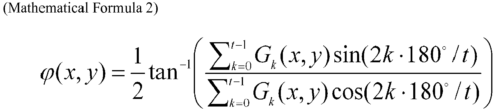
orientation calculating unit 14 then calculates local gradient intensities in predetermined directions θ for each biological curve local region. In the description below, angles are set so that the upward vertical direction in the image is 0 degrees, and a counterclockwise direction is a positive direction. The directions in which local gradient intensities are calculated are the four directions expressed as θ = k × 45 degrees (k = 0, 1, 2, 3). For each pixel in each biological curve local region, a differential filter of the respective directions θ shown below in the mathematical formula (1) is applied to the palm image, and the total sums of the absolute values of θ-direction differential filter responses in the biological curve local region are set as the local gradient intensities Gk(x, y) in the directions θ in the biological curve local region. - The local
orientation calculating unit 14 then obtains a biological curve vector indicating the orientation of the biological curve pixel of the biological curve, from the local gradient intensities in the four directions in each biological curve local region. For each biological curve pixel (x, y), ϕ(x, y) is calculated according to the mathematical formula (2) shown below, where t = 4. The mathematical formula (2) shown below represents local gradient intensities as vectors in which the directions are θ, and the size is Gk(x, y). Accordingly, the total sum of the vectors of these four directions is the vector indicating the orientation of the edge of the biological curve. The vector is then rotated 90 degrees, so that a biological curve orientation vector can be obtained. That is, ϕ(x, y) + 90 degrees represents the biological curve local orientation. - In this embodiment, no distinction is made between directions with a difference of 180 degrees, such as 45 degrees and 225 degrees, and a local orientation is calculated as an angle between 0 degrees and 180 degrees. Therefore, in the mathematical formula (2) shown below, a biological curve orientation vector is calculated from a vector having an angle of a value twice greater than θ, and the orientation obtained by adding 90 degrees to half the angle formed by the biological curve orientation vector is set as the local orientation of the biological curve.

- The mean
orientation calculating unit 15 then calculates the mean orientation Φ of the biological curve from the statistical amount of N local orientations calculated from N biological curve local regions (step S5). For example, the meanorientation calculating unit 15 calculates the mean value or the median value of N values as the mean orientation. In a case where two or more biological curves are used, the mean orientations of the respective biological curves are calculated, and are set as Φ1, Φ2, ..., respectively.FIG. 5 is a diagram showing an example of the mean orientations of respective biological curves.FIG. 5 shows the mean orientation ΦL of the contour of the little finger side (left side), the mean orientation ΦR of the contour of the thumb side (right side), and the mean orientation of these orientations. - The correction
angle calculating unit 16 then calculates a rotation correction angle from the mean direction calculated from the respective biological curves (step S6). In a case where the mean orientation of a single biological curve is calculated, the value obtained by multiplying the mean direction by -1 is set as the rotation correction angle. In a case where the mean orientation of two or more biological curves is calculated, the value obtained by multiplying the mean value of the mean orientations Φ1, Φ2, ... by -1 is set as the rotation correction angle. - The corrected
image acquiring unit 17 then rotates the palm image by the rotation correction angle, to create a corrected image (step S7). In this step, the center of rotation is the center of the palm image, or is the center of the gravity coordinates of an image that has the foreground region of the palm image as 1 and the background region as 0.FIG. 6 shows an example of rotation correction in a case where the right and left contours of the palm are used as the biological curves. Since the mean orientation of the two biological curves is represented by Φmean, the rotation correction angle is -Φmean, and an image obtained by rotating the biological image by -Φmean about the image center O is obtained as the corrected image. - The biological
feature extracting unit 20 then extracts a biological feature from the corrected image (step S8). The biological feature is the vein pattern, the palm print, the shape of the palm, or the like. The vein pattern includes the coordinates and the orientations of the end points and the branch points of the veins, joint information about two branch points, and the like. The registeringunit 30 then associates the biological feature extracted in step S8 with the attribute information acquired in step S1, and registers the attribute information and the biological feature in the database 50 (step S9). The biological feature registered in step S9 is referred to as a registered biological feature. Through the above procedures, the registration process is completed. - (Authentication Process) Next, the authentication process is described.
FIG. 7 is a flowchart showing an example of the authentication process in detail. As shown in the example inFIG. 7 , steps S11 through S18 are the same as steps S1 through S8 inFIG. 3 . The biological feature obtained in step S18 is referred to as a verification biological feature. After step S18 is carried out, the authenticatingunit 40 reads, from thedatabase 50, the registered biological feature associated with the same attribute information as that acquired in step S11, and checks the verification biological feature against the registered biological feature (step S19). Specifically, the authenticatingunit 40 determines whether the degree of similarity between the registered biological feature and the verification biological feature is not lower than a threshold value, and outputs the result of the determination. - According to this embodiment, the orientation of a biological curve is determined through calculation related to the pixels constituting the biological curve, so that the size of a positional shift due to rotation of a palm image. Thus, a rotation angle correction can be obtained at a low computational cost. Also, local orientations are turned into a vector and are thus combined in calculating the biological curve. Accordingly, a very small difference in angle can be expressed, and the accuracy of rotation angle calculation becomes higher. Consequently, an image that achieves a high authentication accuracy can be obtained. Further, the local orientations of the respective pixels constituting the biological curve are calculated, and the rotation angle of the palm image is calculated from the statistical amount of the calculated local orientations. Even if noise appears in part of the biological curve, the noise can be absorbed. Thus, a robust correction angle calculation can be performed.
- In this embodiment, one-to-one authentication in which attribute information is obtained in the authentication process, and the registered biological feature to be checked against is identified with the attribute information has been described. However, this embodiment is not limited to that, and may be applied to one-to-N authentication in which attribute information is not obtained in the authentication process, and a verification biological feature is checked against two or more registered biological features. It should be noted that the same applies to the embodiments described below.
- In a second embodiment, the local
orientation calculating unit 14 calculates the local orientations of a biological curve, using Gabor filters. The Gabor filter is expressed by the mathematical formula (3) shown below. In a case where there is an edge of a component of the filter in a direction θ, a filter response amplifies. This can be used in calculating the local orientation of each biological curve pixel as described below. In the expression below, x' = xcosθ + ysinθ, and y' = -xsinθ + ycosθ.
- In this embodiment, the contour of the little finger side of the palm is used as an example of the biological curve. The number of biological curve pixels and the number of biological curve local regions are N. Each biological curve local region is a rectangle of 7×7 pixels, with the corresponding biological curve pixel being the center. As shown in the example in
FIG. 5 , the upward vertical direction in the image is 0 degrees, and the horizontal directions are ±90 degrees. In the Gabor filter shown in the above mathematical formula (3), x and y represent the coordinates of the pixel, λ represents the wavelength of the filter, θ represents the orientation of the filter, and σ represents the size of the Gaussian variance. As an example of the respective parameters, λ and σ are the mean width of the biological curve, and θ is the eight directions expressed as θ = k × 22.5 degrees (k = 0, ±1, ±2, ±3, 4). - First, for the pixels (i, j) included in each biological curve local region, the local
orientation calculating unit 14 determines filter responses Gk(x, y, i, j) of the eight directions according to the above mathematical formula (3), and calculates Gk(x, y) by adding up Gk(x, y, i, j) of 7×7 or 49 pixels. The localorientation calculating unit 14 then calculates ϕ(x, y) of each biological curve pixel (x, y) according to the mathematical formula (2) of the first embodiment, with t being 8. As Gk(x, y) represents the intensity of the edge in each direction, the total sum of the vectors that have the direction θ and the size Gk(x, y) is calculated, so that the biological curve vector indicating the local orientations of the biological curve can be obtained. That is, ϕ(x, y) indicates the orientation of the biological curve vector. The process to be performed thereafter is the same as that in the first embodiment, with the biological curve local orientation being ϕ(x, y). - According to this embodiment, Gabor filter responses are calculated with respect to the pixels constituting a biological curve of a palm image, and thus, rotation angle correction can be performed at a low computational cost. Although a Gabor filter has discrete orientations, filter responses are turned into a vector and are combined, so that a very small difference in angle between local orientations of the respective pixels constituting the biological curve can be expressed, and the accuracy of rotation angle calculation becomes higher. Thus, an image that achieves a high authentication accuracy can be obtained.
- In a third embodiment, the local
orientation calculating unit 14 calculates local orientations of a biological curve, using orientation concentration ratios IR. An orientation concentration ratio IR(x, y) is expressed by the mathematical formula (4) shown below, and is calculated for each biological curve pixel. In the mathematical formula (4),
orientation calculating unit 14 then calculates the mean value or the median value of the local orientations of the valid pixels, and sets the calculated value as the mean orientation Φ of the biological curve. The process to be performed thereafter is the same as that in the first embodiment.
- According to this embodiment, the orientation of a biological curve is determined through calculation related to the pixels constituting the biological curve, and thus, rotation angle correction can be performed at a low computational cost. Also, local orientations are turned into a vector and are combined in calculating the biological curve. With this, a very small difference in angle can be expressed, and the accuracy of rotation angle calculation can be increased. Accordingly, an image that achieves a high authentication accuracy can be obtained. In a case where noise that is an edge component not in the curve orientation appears in the biological curve, and the biological curve includes an unclear region, the pixels causing the noise are regarded as invalid pixels and are not used in calculating the biological curve orientation. Thus, the biological curve orientation can be calculated without any influence of noise, and robust rotation correction can be performed.
-
FIG. 8 is a block diagram showing the respective functions to be obtained through execution of a biological authentication program according to a third embodiment. The configuration of the biometric authentication device is the same as that shown inFIG. 1 . As shown in the example inFIG. 8 , the difference fromFIG. 2 is that the correctingunit 10 further includes a meanorientation correcting unit 18. -
FIG. 9 is a flowchart showing an example process to be performed in place of steps S1 through S7 ofFIG. 3 and steps S11 through S17 ofFIG. 7 . As shown in the example inFIG. 9 , steps S21 through S26 are the same as steps S1 through S6 ofFIG. 3 and steps S11 through S16 ofFIG. 7 . After step S26 is carried out, the meanorientation correcting unit 18 calculates a corrected rotation correction angle from the local orientations of the biological curve and the mean orientation of these local orientations (step S27). After that, the correctedimage acquiring unit 17 rotates the biological image by the rotation correction angle, to acquire a corrected image (step S28). - In the description below, step S27 is described in detail. The mean
orientation correcting unit 18 determines valid pixels that are some of biological curve pixels (x, y) having local orientations ϕ(x, y) calculated by the localorientation calculating unit 14. The angle differences between the local orientations ϕ(x, y) of the valid pixels and the mean orientation Φ of the biological curve calculated by the meanorientation calculating unit 15 are equal to or smaller than a predetermined threshold value. The meanorientation correcting unit 18 also determines invalid pixels. The angle differences between the local orientations ϕ(x, y) of the invalid pixels and the mean orientation Φ of the biological curve are larger than the predetermined threshold value. The angle difference between the mean orientation Φ and a local orientation ϕ(x, y), and the predetermined threshold value are cos(Φ - cp(x, y)) and cos(π/8), respectively, for example. The meanorientation correcting unit 18 then calculates the mean value or the median value of the orientation directions of the valid pixels among the biological curve pixels, and sets the calculated value as a corrected biological curve mean orientation Φ'. That is, a rotation correction angle is determined. -
FIG. 10 is a diagram showing an example of irregular noise.FIG. 11 is a diagram showing an example of the biological curve from which the irregular noise has been removed. Such irregular noise might appear in a case where an object other than a palm exists in the background region. Even in such a case, the local orientation of the portion of the biological curve at which the irregular noise has appeared greatly deviates from the mean orientation. Thus, only the irregular portion can be removed as shown inFIG. 11 , and the influence of noise can be further reduced. - According to this embodiment, the orientation of a biological curve is determined through calculation related to the pixels constituting the biological curve, and thus, rotation angle correction can be performed at a low computational cost. Also, local orientations are turned into a vector and are combined in calculating the biological curve. With this, a very small difference in angle can be expressed, and the accuracy of rotation angle calculation can be increased. Accordingly, an image that achieves a high authentication accuracy can be obtained. In a case where an irregular portion appears in a biological curve, pixels having large angle differences between the mean orientation Φ and the local orientations ϕ(x, y) are regarded as invalid pixels, and these invalid pixels are not used in calculating the biological curve orientation. Thus, the biological curve orientation can be calculated without any influence of irregular noise appearing in the biological curve, and robust rotation correction can be performed.
- In each of the above described embodiments, the biological
curve detecting unit 11 functions as an example of the line extracting unit that extracts at least one line from the contours of a palm and the principal lines of the palm in an image of the palm. Thepixel extracting unit 12 functions as an example of the pixel extracting unit that extracts the pixels of the line extracted by the line extracting unit. The localregion setting unit 13 functions as an example of the local region setting unit that sets a local region including each corresponding one of the pixels. The localorientation calculating unit 14 functions as an example of the local orientation calculating unit that calculates local orientations of the line extracted by the line extracting unit, in accordance with the gradient intensities of each corresponding one of the local regions. The meanorientation calculating unit 15 functions as an example of the orientation calculating unit that calculates the orientation of the palm from the statistical amount of the respective local orientations.
Claims (15)
- A biological image processing device comprising:a line extracting unit configured to extract at least one line from contours of a palm and principal lines of the palm shown in an image of the palm;a pixel extracting unit configured to extract pixels of the line extracted by the line extracting unit;a local region setting unit configured to set a local region for each of the pixels, each local region including each corresponding one of the pixels;a local orientation calculating unit configured to calculate, for each local region, local orientations of the line extracted by the line extracting unit, in accordance with gradient intensities related to respective orientations of each corresponding local region; andan orientation calculating unit configured to calculate an orientation of the palm in accordance with a statistical amount of the respective local orientations.
- The biological image processing device as claimed in claim 1, wherein:the line extracting unit extracts a plurality of lines from the contours and the principal lines of the palm; andthe orientation calculating unit calculates the orientation of the palm in accordance with a statistical amount of the local orientations of the respective lines.
- The biological image processing device as claimed in claim 1 or 2, wherein the local region setting unit sets rectangular regions including the respective pixels as the local regions.
- The biological image processing device as claimed in claim 1 or 2, wherein the local region setting unit sets circles around the respective pixels as the local regions.
- The biological image processing device as claimed in any of claims 1 through 4, wherein the orientation calculating unit calculates a mean orientation of the at least one line extracted by the line extracting unit, in accordance with a statistical amount of the local orientations, and calculates the orientation of the palm from the mean orientation.
- The biological image processing device as claimed in any of claims 1 through 5, wherein the local orientation calculating unit calculates the local orientations, using a plurality of Gabor filters of different directions.
- The biological image processing device as claimed in any of claims 1 through 5, wherein the local orientation calculating unit classifies the pixels into valid pixels and invalid pixels in accordance with gradient intensity variation among the local regions, calculates the local orientations of the valid pixels, and calculates the orientation of the palm from a statistical amount of the respective local orientations of the valid pixels.
- A biological image processing method, comprising:extracting at least one line from contours of a palm and principal lines of the palm shown in an image of the palm;extracting pixels of the line extracted by the line extracting unit;setting a local region for each of the pixels, each local region including each corresponding one of the pixels;calculating, for each local region, local orientations of the line extracted by the line extracting unit, in accordance with gradient intensities related to respective orientations of each corresponding local region; andcalculating an orientation of the palm in accordance with a statistical amount of the respective local orientations.
- The biological image processing method as claimed in claim 8, wherein:in the extracting of at least one line, a plurality of lines are extracted from the contours and the principal lines of the palm; andin the calculating of an orientation, the orientation of the palm is calculated in accordance with a statistical amount of the local orientations of the respective lines.
- The biological image processing method as claimed in claim 8 or 9, wherein in the setting, rectangular regions including the respective pixels are set as the local regions.
- The biological image processing method as claimed in claim 8 or 9, wherein in the setting, circles around the respective pixels are set as the local regions.
- The biological image processing method as claimed in any of claims 8 through 11, wherein in the calculating of an orientation, a mean orientation of the at least one line extracted by the extracting of at least one line is calculated in accordance with a statistical amount of the local orientations, and the orientation of the palm is calculated from the mean orientation.
- The biological image processing method as claimed in any of claims 8 through 12, wherein in the calculating of an orientation, the local orientations are calculated, using a plurality of Gabor filters of different directions.
- The biological image processing method as claimed in any of claims 8 through 13, wherein in the calculating of an orientation, the pixels are calculated into valid pixels and invalid pixels in accordance with gradient intensity variation among the local regions, the local orientations of the valid pixels are calculated, and the orientation of the palm is calculated from a statistical amount of the respective local orientations of the valid pixels.
- A biological image processing program for causing a computer to carry out:a process of extracting at least one line from contours of a palm and principal lines of the palm shown in an image of the palm;a process of extracting pixels of the extracted line;a process of setting a local region for each of the pixels, each local region including each corresponding one of the pixels;a process of calculating, for each local region, local orientations of the extracted line, in accordance with gradient intensities related to respective orientations of each corresponding local region; anda process of calculating an orientation of the palm in accordance with a statistical amount of the respective local orientations.
Applications Claiming Priority (1)
| Application Number | Priority Date | Filing Date | Title |
|---|---|---|---|
| JP2016041395A JP6776559B2 (en) | 2016-03-03 | 2016-03-03 | Bioimage processing device, bioimage processing method and bioimage processing program |
Publications (2)
| Publication Number | Publication Date |
|---|---|
| EP3214575A1 true EP3214575A1 (en) | 2017-09-06 |
| EP3214575B1 EP3214575B1 (en) | 2019-02-27 |
Family
ID=58016582
Family Applications (1)
| Application Number | Title | Priority Date | Filing Date |
|---|---|---|---|
| EP17155367.0A Active EP3214575B1 (en) | 2016-03-03 | 2017-02-09 | Biological image processing device, biological image processing method, and biological image processing program |
Country Status (3)
| Country | Link |
|---|---|
| US (1) | US10095912B2 (en) |
| EP (1) | EP3214575B1 (en) |
| JP (1) | JP6776559B2 (en) |
Families Citing this family (5)
| Publication number | Priority date | Publication date | Assignee | Title |
|---|---|---|---|---|
| US11017203B1 (en) | 2019-06-19 | 2021-05-25 | Amazon Technologies, Inc. | Utilizing sensor data for automated user identification |
| US10902237B1 (en) | 2019-06-19 | 2021-01-26 | Amazon Technologies, Inc. | Utilizing sensor data for automated user identification |
| US11941629B2 (en) | 2019-09-27 | 2024-03-26 | Amazon Technologies, Inc. | Electronic device for automated user identification |
| US11270102B2 (en) * | 2020-06-29 | 2022-03-08 | Amazon Technologies, Inc. | Electronic device for automated user identification |
| CN117058413A (en) * | 2023-08-03 | 2023-11-14 | 上海银欣高新技术发展股份有限公司 | Palm vein feature extraction method, system, media and electronic equipment |
Citations (1)
| Publication number | Priority date | Publication date | Assignee | Title |
|---|---|---|---|---|
| JP2009003492A (en) | 2007-06-19 | 2009-01-08 | Hitachi Ltd | Mobile terminal with personal authentication function |
Family Cites Families (19)
| Publication number | Priority date | Publication date | Assignee | Title |
|---|---|---|---|---|
| DE69228741T2 (en) * | 1991-10-02 | 1999-09-02 | Fujitsu Ltd. | METHOD FOR DETERMINING THE LOCAL ORIENTATION OF A CONTOUR SEGMENT AND FOR DETERMINING LINES AND CORNERS |
| JP2725599B2 (en) * | 1994-06-21 | 1998-03-11 | 日本電気株式会社 | Ridge direction extraction device |
| US6298157B1 (en) * | 1998-02-27 | 2001-10-02 | Adobe Systems Incorporated | Locating and aligning embedded images |
| JP2002290707A (en) * | 2001-03-26 | 2002-10-04 | Olympus Optical Co Ltd | Image processing device |
| JP2007524143A (en) * | 2003-06-12 | 2007-08-23 | ザ ホンコン ポリテクニック ユニヴァーシティ | Palmprint authentication method |
| US20060165264A1 (en) | 2005-01-26 | 2006-07-27 | Hirofumi Saitoh | Method and apparatus for acquiring images, and verification method and verification apparatus |
| JP2006209363A (en) | 2005-01-26 | 2006-08-10 | Sanyo Electric Co Ltd | Collating method and device |
| MX2009004749A (en) | 2006-11-03 | 2009-09-28 | Snowflake Technologies Corp | Method and apparatus for extraction and matching of biometric detail. |
| JP2008152512A (en) * | 2006-12-18 | 2008-07-03 | Seiko Epson Corp | Image processing apparatus, electronic apparatus, image processing method, and image processing program |
| JP4833115B2 (en) * | 2007-03-02 | 2011-12-07 | Kddi株式会社 | Palmprint authentication device, mobile phone terminal, program, and palmprint authentication method |
| JP2008250774A (en) * | 2007-03-30 | 2008-10-16 | Denso Corp | Information device operation device |
| WO2011030441A1 (en) * | 2009-09-11 | 2011-03-17 | 富士通株式会社 | Biometric authentication device, biometric authentication system, and biometric authentication method |
| JP2011203822A (en) | 2010-03-24 | 2011-10-13 | Sony Corp | Biometrics device, biometrics method and program |
| JP5747642B2 (en) | 2011-05-06 | 2015-07-15 | 富士通株式会社 | Biometric authentication device, biometric authentication system, biometric authentication server, biometric authentication client, and biometric authentication device control method |
| US8811675B2 (en) * | 2012-03-30 | 2014-08-19 | MindTree Limited | Circular object identification system |
| JP2015082287A (en) * | 2013-10-24 | 2015-04-27 | 日本電気株式会社 | Image processing apparatus, image processing method, and image processing program |
| US9646201B1 (en) * | 2014-06-05 | 2017-05-09 | Leap Motion, Inc. | Three dimensional (3D) modeling of a complex control object |
| US20160026857A1 (en) * | 2014-07-23 | 2016-01-28 | Lsi Corporation | Image processor comprising gesture recognition system with static hand pose recognition based on dynamic warping |
| KR102231676B1 (en) * | 2014-12-23 | 2021-03-25 | 한국전자통신연구원 | Apparatus and method for generating sensory effect metadata |
-
2016
- 2016-03-03 JP JP2016041395A patent/JP6776559B2/en not_active Expired - Fee Related
-
2017
- 2017-02-06 US US15/424,946 patent/US10095912B2/en active Active
- 2017-02-09 EP EP17155367.0A patent/EP3214575B1/en active Active
Patent Citations (1)
| Publication number | Priority date | Publication date | Assignee | Title |
|---|---|---|---|---|
| JP2009003492A (en) | 2007-06-19 | 2009-01-08 | Hitachi Ltd | Mobile terminal with personal authentication function |
Non-Patent Citations (3)
| Title |
|---|
| FEI LUNKE ET AL: "Half-orientation extraction of palmprint features", PATTERN RECOGNITION LETTERS, vol. 69, 1 January 2016 (2016-01-01), pages 35 - 41, XP029365739, ISSN: 0167-8655, DOI: 10.1016/J.PATREC.2015.10.003 * |
| LI W ET AL: "Image alignment based on invariant features for palmprint identification", SIGNAL PROCESSING. IMAGE COMMUNICAT, ELSEVIER SCIENCE PUBLISHERS, AMSTERDAM, NL, vol. 18, no. 5, 1 May 2003 (2003-05-01), pages 373 - 379, XP004416075, ISSN: 0923-5965, DOI: 10.1016/S0923-5965(03)00011-0 * |
| WEI JIA ET AL: "Fast palmprint retrieval using principal lines", SYSTEMS, MAN AND CYBERNETICS, 2009. SMC 2009. IEEE INTERNATIONAL CONFERENCE ON, IEEE, PISCATAWAY, NJ, USA, 11 October 2009 (2009-10-11), pages 4118 - 4123, XP031575306, ISBN: 978-1-4244-2793-2 * |
Also Published As
| Publication number | Publication date |
|---|---|
| EP3214575B1 (en) | 2019-02-27 |
| JP6776559B2 (en) | 2020-10-28 |
| US20170255815A1 (en) | 2017-09-07 |
| JP2017157095A (en) | 2017-09-07 |
| US10095912B2 (en) | 2018-10-09 |
Similar Documents
| Publication | Publication Date | Title |
|---|---|---|
| EP3214575A1 (en) | Biological image processing device, biological image processing method, and biological image processing program | |
| US9792512B2 (en) | Device to extract biometric feature vector, method to extract biometric feature vector, and computer-readable, non-transitory medium | |
| US7298874B2 (en) | Iris image data processing for use with iris recognition system | |
| US10460207B2 (en) | Image processing device, image processing method and computer-readable non-transitory medium | |
| US9070025B2 (en) | Biometric information processing apparatus, biometric information processing method | |
| JP2008210141A (en) | Information extraction method, information extraction device, program, registration device, and verification device | |
| CN110717372A (en) | Identity verification method and device based on finger vein recognition | |
| US20160188975A1 (en) | Biometric identification via retina scanning | |
| WO2010119500A1 (en) | Biometric information registration device, biometric information registration method, computer program for registering biometric information, biometric authentication device, biometric authentication method, and computer program for biometric authentication | |
| CN108292440B (en) | Method for identifying characteristic points of a calibration pattern within an image of the calibration pattern | |
| TW200910223A (en) | Image processing apparatus and image processing method | |
| US10349832B2 (en) | Method of detecting boundary between iris and sclera | |
| WO2018176514A1 (en) | Fingerprint registration method and device | |
| WO2017113083A1 (en) | Method and apparatus for iris recognition | |
| JP2019121187A (en) | Image processing apparatus, image processing method, and image processing program | |
| KR101660596B1 (en) | Method for modifying gradient of facial shape, and system for the same | |
| CN112926516B (en) | Robust finger vein image region-of-interest extraction method | |
| Wieclaw | Gradient based fingerprint orientation field estimation | |
| CN112101379B (en) | Shape matching method, computer equipment and storage device | |
| CN104809428A (en) | Biont sign authentication method | |
| JP2015094968A (en) | Biological information extracting device, biological information extraction method, and biological information extraction program | |
| Alonso-Montes et al. | Pixel parallel vessel tree extraction for a personal authentication system | |
| EP4379652A1 (en) | Determination method, determination program, and information processing device | |
| CN117635404A (en) | An image encryption method and device | |
| WO2015056210A2 (en) | Method of authenticating a person |
Legal Events
| Date | Code | Title | Description |
|---|---|---|---|
| PUAI | Public reference made under article 153(3) epc to a published international application that has entered the european phase |
Free format text: ORIGINAL CODE: 0009012 |
|
| STAA | Information on the status of an ep patent application or granted ep patent |
Free format text: STATUS: THE APPLICATION HAS BEEN PUBLISHED |
|
| AK | Designated contracting states |
Kind code of ref document: A1 Designated state(s): AL AT BE BG CH CY CZ DE DK EE ES FI FR GB GR HR HU IE IS IT LI LT LU LV MC MK MT NL NO PL PT RO RS SE SI SK SM TR |
|
| AX | Request for extension of the european patent |
Extension state: BA ME |
|
| STAA | Information on the status of an ep patent application or granted ep patent |
Free format text: STATUS: REQUEST FOR EXAMINATION WAS MADE |
|
| 17P | Request for examination filed |
Effective date: 20180222 |
|
| RBV | Designated contracting states (corrected) |
Designated state(s): AL AT BE BG CH CY CZ DE DK EE ES FI FR GB GR HR HU IE IS IT LI LT LU LV MC MK MT NL NO PL PT RO RS SE SI SK SM TR |
|
| STAA | Information on the status of an ep patent application or granted ep patent |
Free format text: STATUS: EXAMINATION IS IN PROGRESS |
|
| REG | Reference to a national code |
Ref country code: DE Ref legal event code: R079 Ref document number: 602017002255 Country of ref document: DE Free format text: PREVIOUS MAIN CLASS: G06K0009000000 Ipc: G06K0009460000 |
|
| 17Q | First examination report despatched |
Effective date: 20180822 |
|
| GRAP | Despatch of communication of intention to grant a patent |
Free format text: ORIGINAL CODE: EPIDOSNIGR1 |
|
| STAA | Information on the status of an ep patent application or granted ep patent |
Free format text: STATUS: GRANT OF PATENT IS INTENDED |
|
| RIC1 | Information provided on ipc code assigned before grant |
Ipc: G06K 9/00 20060101ALI20180918BHEP Ipc: G06K 9/32 20060101ALI20180918BHEP Ipc: G06K 9/46 20060101AFI20180918BHEP |
|
| INTG | Intention to grant announced |
Effective date: 20181009 |
|
| RAP1 | Party data changed (applicant data changed or rights of an application transferred) |
Owner name: FUJITSU LIMITED |
|
| RIN1 | Information on inventor provided before grant (corrected) |
Inventor name: MATSUNAMI, TOMOAKI |
|
| GRAS | Grant fee paid |
Free format text: ORIGINAL CODE: EPIDOSNIGR3 |
|
| GRAA | (expected) grant |
Free format text: ORIGINAL CODE: 0009210 |
|
| STAA | Information on the status of an ep patent application or granted ep patent |
Free format text: STATUS: THE PATENT HAS BEEN GRANTED |
|
| AK | Designated contracting states |
Kind code of ref document: B1 Designated state(s): AL AT BE BG CH CY CZ DE DK EE ES FI FR GB GR HR HU IE IS IT LI LT LU LV MC MK MT NL NO PL PT RO RS SE SI SK SM TR |
|
| REG | Reference to a national code |
Ref country code: GB Ref legal event code: FG4D |
|
| REG | Reference to a national code |
Ref country code: CH Ref legal event code: EP |
|
| REG | Reference to a national code |
Ref country code: AT Ref legal event code: REF Ref document number: 1102438 Country of ref document: AT Kind code of ref document: T Effective date: 20190315 |
|
| REG | Reference to a national code |
Ref country code: IE Ref legal event code: FG4D |
|
| REG | Reference to a national code |
Ref country code: DE Ref legal event code: R096 Ref document number: 602017002255 Country of ref document: DE |
|
| REG | Reference to a national code |
Ref country code: NL Ref legal event code: MP Effective date: 20190227 |
|
| REG | Reference to a national code |
Ref country code: LT Ref legal event code: MG4D |
|
| PG25 | Lapsed in a contracting state [announced via postgrant information from national office to epo] |
Ref country code: NO Free format text: LAPSE BECAUSE OF FAILURE TO SUBMIT A TRANSLATION OF THE DESCRIPTION OR TO PAY THE FEE WITHIN THE PRESCRIBED TIME-LIMIT Effective date: 20190527 Ref country code: PT Free format text: LAPSE BECAUSE OF FAILURE TO SUBMIT A TRANSLATION OF THE DESCRIPTION OR TO PAY THE FEE WITHIN THE PRESCRIBED TIME-LIMIT Effective date: 20190627 Ref country code: SE Free format text: LAPSE BECAUSE OF FAILURE TO SUBMIT A TRANSLATION OF THE DESCRIPTION OR TO PAY THE FEE WITHIN THE PRESCRIBED TIME-LIMIT Effective date: 20190227 Ref country code: FI Free format text: LAPSE BECAUSE OF FAILURE TO SUBMIT A TRANSLATION OF THE DESCRIPTION OR TO PAY THE FEE WITHIN THE PRESCRIBED TIME-LIMIT Effective date: 20190227 Ref country code: LT Free format text: LAPSE BECAUSE OF FAILURE TO SUBMIT A TRANSLATION OF THE DESCRIPTION OR TO PAY THE FEE WITHIN THE PRESCRIBED TIME-LIMIT Effective date: 20190227 Ref country code: NL Free format text: LAPSE BECAUSE OF FAILURE TO SUBMIT A TRANSLATION OF THE DESCRIPTION OR TO PAY THE FEE WITHIN THE PRESCRIBED TIME-LIMIT Effective date: 20190227 |
|
| PG25 | Lapsed in a contracting state [announced via postgrant information from national office to epo] |
Ref country code: IS Free format text: LAPSE BECAUSE OF FAILURE TO SUBMIT A TRANSLATION OF THE DESCRIPTION OR TO PAY THE FEE WITHIN THE PRESCRIBED TIME-LIMIT Effective date: 20190627 Ref country code: BG Free format text: LAPSE BECAUSE OF FAILURE TO SUBMIT A TRANSLATION OF THE DESCRIPTION OR TO PAY THE FEE WITHIN THE PRESCRIBED TIME-LIMIT Effective date: 20190527 Ref country code: GR Free format text: LAPSE BECAUSE OF FAILURE TO SUBMIT A TRANSLATION OF THE DESCRIPTION OR TO PAY THE FEE WITHIN THE PRESCRIBED TIME-LIMIT Effective date: 20190528 Ref country code: LV Free format text: LAPSE BECAUSE OF FAILURE TO SUBMIT A TRANSLATION OF THE DESCRIPTION OR TO PAY THE FEE WITHIN THE PRESCRIBED TIME-LIMIT Effective date: 20190227 Ref country code: HR Free format text: LAPSE BECAUSE OF FAILURE TO SUBMIT A TRANSLATION OF THE DESCRIPTION OR TO PAY THE FEE WITHIN THE PRESCRIBED TIME-LIMIT Effective date: 20190227 Ref country code: RS Free format text: LAPSE BECAUSE OF FAILURE TO SUBMIT A TRANSLATION OF THE DESCRIPTION OR TO PAY THE FEE WITHIN THE PRESCRIBED TIME-LIMIT Effective date: 20190227 |
|
| REG | Reference to a national code |
Ref country code: AT Ref legal event code: MK05 Ref document number: 1102438 Country of ref document: AT Kind code of ref document: T Effective date: 20190227 |
|
| PG25 | Lapsed in a contracting state [announced via postgrant information from national office to epo] |
Ref country code: RO Free format text: LAPSE BECAUSE OF FAILURE TO SUBMIT A TRANSLATION OF THE DESCRIPTION OR TO PAY THE FEE WITHIN THE PRESCRIBED TIME-LIMIT Effective date: 20190227 Ref country code: AL Free format text: LAPSE BECAUSE OF FAILURE TO SUBMIT A TRANSLATION OF THE DESCRIPTION OR TO PAY THE FEE WITHIN THE PRESCRIBED TIME-LIMIT Effective date: 20190227 Ref country code: CZ Free format text: LAPSE BECAUSE OF FAILURE TO SUBMIT A TRANSLATION OF THE DESCRIPTION OR TO PAY THE FEE WITHIN THE PRESCRIBED TIME-LIMIT Effective date: 20190227 Ref country code: IT Free format text: LAPSE BECAUSE OF FAILURE TO SUBMIT A TRANSLATION OF THE DESCRIPTION OR TO PAY THE FEE WITHIN THE PRESCRIBED TIME-LIMIT Effective date: 20190227 Ref country code: EE Free format text: LAPSE BECAUSE OF FAILURE TO SUBMIT A TRANSLATION OF THE DESCRIPTION OR TO PAY THE FEE WITHIN THE PRESCRIBED TIME-LIMIT Effective date: 20190227 Ref country code: DK Free format text: LAPSE BECAUSE OF FAILURE TO SUBMIT A TRANSLATION OF THE DESCRIPTION OR TO PAY THE FEE WITHIN THE PRESCRIBED TIME-LIMIT Effective date: 20190227 Ref country code: ES Free format text: LAPSE BECAUSE OF FAILURE TO SUBMIT A TRANSLATION OF THE DESCRIPTION OR TO PAY THE FEE WITHIN THE PRESCRIBED TIME-LIMIT Effective date: 20190227 Ref country code: SK Free format text: LAPSE BECAUSE OF FAILURE TO SUBMIT A TRANSLATION OF THE DESCRIPTION OR TO PAY THE FEE WITHIN THE PRESCRIBED TIME-LIMIT Effective date: 20190227 |
|
| REG | Reference to a national code |
Ref country code: DE Ref legal event code: R097 Ref document number: 602017002255 Country of ref document: DE |
|
| PG25 | Lapsed in a contracting state [announced via postgrant information from national office to epo] |
Ref country code: PL Free format text: LAPSE BECAUSE OF FAILURE TO SUBMIT A TRANSLATION OF THE DESCRIPTION OR TO PAY THE FEE WITHIN THE PRESCRIBED TIME-LIMIT Effective date: 20190227 Ref country code: SM Free format text: LAPSE BECAUSE OF FAILURE TO SUBMIT A TRANSLATION OF THE DESCRIPTION OR TO PAY THE FEE WITHIN THE PRESCRIBED TIME-LIMIT Effective date: 20190227 |
|
| PG25 | Lapsed in a contracting state [announced via postgrant information from national office to epo] |
Ref country code: AT Free format text: LAPSE BECAUSE OF FAILURE TO SUBMIT A TRANSLATION OF THE DESCRIPTION OR TO PAY THE FEE WITHIN THE PRESCRIBED TIME-LIMIT Effective date: 20190227 |
|
| PLBE | No opposition filed within time limit |
Free format text: ORIGINAL CODE: 0009261 |
|
| STAA | Information on the status of an ep patent application or granted ep patent |
Free format text: STATUS: NO OPPOSITION FILED WITHIN TIME LIMIT |
|
| 26N | No opposition filed |
Effective date: 20191128 |
|
| PG25 | Lapsed in a contracting state [announced via postgrant information from national office to epo] |
Ref country code: SI Free format text: LAPSE BECAUSE OF FAILURE TO SUBMIT A TRANSLATION OF THE DESCRIPTION OR TO PAY THE FEE WITHIN THE PRESCRIBED TIME-LIMIT Effective date: 20190227 |
|
| PG25 | Lapsed in a contracting state [announced via postgrant information from national office to epo] |
Ref country code: TR Free format text: LAPSE BECAUSE OF FAILURE TO SUBMIT A TRANSLATION OF THE DESCRIPTION OR TO PAY THE FEE WITHIN THE PRESCRIBED TIME-LIMIT Effective date: 20190227 |
|
| REG | Reference to a national code |
Ref country code: CH Ref legal event code: PL |
|
| REG | Reference to a national code |
Ref country code: BE Ref legal event code: MM Effective date: 20200229 |
|
| PG25 | Lapsed in a contracting state [announced via postgrant information from national office to epo] |
Ref country code: LU Free format text: LAPSE BECAUSE OF NON-PAYMENT OF DUE FEES Effective date: 20200209 Ref country code: MC Free format text: LAPSE BECAUSE OF FAILURE TO SUBMIT A TRANSLATION OF THE DESCRIPTION OR TO PAY THE FEE WITHIN THE PRESCRIBED TIME-LIMIT Effective date: 20190227 |
|
| PG25 | Lapsed in a contracting state [announced via postgrant information from national office to epo] |
Ref country code: CH Free format text: LAPSE BECAUSE OF NON-PAYMENT OF DUE FEES Effective date: 20200229 Ref country code: LI Free format text: LAPSE BECAUSE OF NON-PAYMENT OF DUE FEES Effective date: 20200229 |
|
| PG25 | Lapsed in a contracting state [announced via postgrant information from national office to epo] |
Ref country code: IE Free format text: LAPSE BECAUSE OF NON-PAYMENT OF DUE FEES Effective date: 20200209 |
|
| PG25 | Lapsed in a contracting state [announced via postgrant information from national office to epo] |
Ref country code: BE Free format text: LAPSE BECAUSE OF NON-PAYMENT OF DUE FEES Effective date: 20200229 |
|
| REG | Reference to a national code |
Ref country code: DE Ref legal event code: R079 Ref document number: 602017002255 Country of ref document: DE Free format text: PREVIOUS MAIN CLASS: G06K0009460000 Ipc: G06V0030180000 |
|
| PG25 | Lapsed in a contracting state [announced via postgrant information from national office to epo] |
Ref country code: MT Free format text: LAPSE BECAUSE OF FAILURE TO SUBMIT A TRANSLATION OF THE DESCRIPTION OR TO PAY THE FEE WITHIN THE PRESCRIBED TIME-LIMIT Effective date: 20190227 Ref country code: CY Free format text: LAPSE BECAUSE OF FAILURE TO SUBMIT A TRANSLATION OF THE DESCRIPTION OR TO PAY THE FEE WITHIN THE PRESCRIBED TIME-LIMIT Effective date: 20190227 |
|
| PG25 | Lapsed in a contracting state [announced via postgrant information from national office to epo] |
Ref country code: MK Free format text: LAPSE BECAUSE OF FAILURE TO SUBMIT A TRANSLATION OF THE DESCRIPTION OR TO PAY THE FEE WITHIN THE PRESCRIBED TIME-LIMIT Effective date: 20190227 |
|
| PGFP | Annual fee paid to national office [announced via postgrant information from national office to epo] |
Ref country code: GB Payment date: 20221230 Year of fee payment: 7 |
|
| PGFP | Annual fee paid to national office [announced via postgrant information from national office to epo] |
Ref country code: DE Payment date: 20221229 Year of fee payment: 7 |
|
| REG | Reference to a national code |
Ref country code: DE Ref legal event code: R119 Ref document number: 602017002255 Country of ref document: DE |
|
| GBPC | Gb: european patent ceased through non-payment of renewal fee |
Effective date: 20240209 |
|
| PG25 | Lapsed in a contracting state [announced via postgrant information from national office to epo] |
Ref country code: DE Free format text: LAPSE BECAUSE OF NON-PAYMENT OF DUE FEES Effective date: 20240903 |
|
| PG25 | Lapsed in a contracting state [announced via postgrant information from national office to epo] |
Ref country code: GB Free format text: LAPSE BECAUSE OF NON-PAYMENT OF DUE FEES Effective date: 20240209 |
|
| PG25 | Lapsed in a contracting state [announced via postgrant information from national office to epo] |
Ref country code: FR Free format text: LAPSE BECAUSE OF NON-PAYMENT OF DUE FEES Effective date: 20240229 |
|
| PG25 | Lapsed in a contracting state [announced via postgrant information from national office to epo] |
Ref country code: GB Free format text: LAPSE BECAUSE OF NON-PAYMENT OF DUE FEES Effective date: 20240209 Ref country code: FR Free format text: LAPSE BECAUSE OF NON-PAYMENT OF DUE FEES Effective date: 20240229 Ref country code: DE Free format text: LAPSE BECAUSE OF NON-PAYMENT OF DUE FEES Effective date: 20240903 |
|
| PGFP | Annual fee paid to national office [announced via postgrant information from national office to epo] |
Ref country code: FR Payment date: 20230110 Year of fee payment: 7 |