EP3214459A1 - Location determination device and method for operating same - Google Patents
Location determination device and method for operating same Download PDFInfo
- Publication number
- EP3214459A1 EP3214459A1 EP15855785.0A EP15855785A EP3214459A1 EP 3214459 A1 EP3214459 A1 EP 3214459A1 EP 15855785 A EP15855785 A EP 15855785A EP 3214459 A1 EP3214459 A1 EP 3214459A1
- Authority
- EP
- European Patent Office
- Prior art keywords
- sensing signal
- neighboring vehicle
- receiving
- ultrasound sensor
- determining
- Prior art date
- Legal status (The legal status is an assumption and is not a legal conclusion. Google has not performed a legal analysis and makes no representation as to the accuracy of the status listed.)
- Granted
Links
Images

Classifications
-
- G—PHYSICS
- G01—MEASURING; TESTING
- G01S—RADIO DIRECTION-FINDING; RADIO NAVIGATION; DETERMINING DISTANCE OR VELOCITY BY USE OF RADIO WAVES; LOCATING OR PRESENCE-DETECTING BY USE OF THE REFLECTION OR RERADIATION OF RADIO WAVES; ANALOGOUS ARRANGEMENTS USING OTHER WAVES
- G01S11/00—Systems for determining distance or velocity not using reflection or reradiation
- G01S11/14—Systems for determining distance or velocity not using reflection or reradiation using ultrasonic, sonic or infrasonic waves
-
- G—PHYSICS
- G08—SIGNALLING
- G08G—TRAFFIC CONTROL SYSTEMS
- G08G1/00—Traffic control systems for road vehicles
- G08G1/01—Detecting movement of traffic to be counted or controlled
- G08G1/04—Detecting movement of traffic to be counted or controlled using optical or ultrasonic detectors
-
- B—PERFORMING OPERATIONS; TRANSPORTING
- B60—VEHICLES IN GENERAL
- B60R—VEHICLES, VEHICLE FITTINGS, OR VEHICLE PARTS, NOT OTHERWISE PROVIDED FOR
- B60R21/00—Arrangements or fittings on vehicles for protecting or preventing injuries to occupants or pedestrians in case of accidents or other traffic risks
- B60R21/01—Electrical circuits for triggering passive safety arrangements, e.g. airbags, safety belt tighteners, in case of vehicle accidents or impending vehicle accidents
- B60R21/013—Electrical circuits for triggering passive safety arrangements, e.g. airbags, safety belt tighteners, in case of vehicle accidents or impending vehicle accidents including means for detecting collisions, impending collisions or roll-over
-
- G—PHYSICS
- G01—MEASURING; TESTING
- G01S—RADIO DIRECTION-FINDING; RADIO NAVIGATION; DETERMINING DISTANCE OR VELOCITY BY USE OF RADIO WAVES; LOCATING OR PRESENCE-DETECTING BY USE OF THE REFLECTION OR RERADIATION OF RADIO WAVES; ANALOGOUS ARRANGEMENTS USING OTHER WAVES
- G01S15/00—Systems using the reflection or reradiation of acoustic waves, e.g. sonar systems
- G01S15/02—Systems using the reflection or reradiation of acoustic waves, e.g. sonar systems using reflection of acoustic waves
- G01S15/06—Systems determining the position data of a target
- G01S15/46—Indirect determination of position data
-
- G—PHYSICS
- G01—MEASURING; TESTING
- G01S—RADIO DIRECTION-FINDING; RADIO NAVIGATION; DETERMINING DISTANCE OR VELOCITY BY USE OF RADIO WAVES; LOCATING OR PRESENCE-DETECTING BY USE OF THE REFLECTION OR RERADIATION OF RADIO WAVES; ANALOGOUS ARRANGEMENTS USING OTHER WAVES
- G01S15/00—Systems using the reflection or reradiation of acoustic waves, e.g. sonar systems
- G01S15/66—Sonar tracking systems
-
- G—PHYSICS
- G01—MEASURING; TESTING
- G01S—RADIO DIRECTION-FINDING; RADIO NAVIGATION; DETERMINING DISTANCE OR VELOCITY BY USE OF RADIO WAVES; LOCATING OR PRESENCE-DETECTING BY USE OF THE REFLECTION OR RERADIATION OF RADIO WAVES; ANALOGOUS ARRANGEMENTS USING OTHER WAVES
- G01S15/00—Systems using the reflection or reradiation of acoustic waves, e.g. sonar systems
- G01S15/87—Combinations of sonar systems
- G01S15/876—Combination of several spaced transmitters or receivers of known location for determining the position of a transponder or a reflector
-
- G—PHYSICS
- G01—MEASURING; TESTING
- G01S—RADIO DIRECTION-FINDING; RADIO NAVIGATION; DETERMINING DISTANCE OR VELOCITY BY USE OF RADIO WAVES; LOCATING OR PRESENCE-DETECTING BY USE OF THE REFLECTION OR RERADIATION OF RADIO WAVES; ANALOGOUS ARRANGEMENTS USING OTHER WAVES
- G01S15/00—Systems using the reflection or reradiation of acoustic waves, e.g. sonar systems
- G01S15/88—Sonar systems specially adapted for specific applications
- G01S15/93—Sonar systems specially adapted for specific applications for anti-collision purposes
- G01S15/931—Sonar systems specially adapted for specific applications for anti-collision purposes of land vehicles
-
- G—PHYSICS
- G01—MEASURING; TESTING
- G01S—RADIO DIRECTION-FINDING; RADIO NAVIGATION; DETERMINING DISTANCE OR VELOCITY BY USE OF RADIO WAVES; LOCATING OR PRESENCE-DETECTING BY USE OF THE REFLECTION OR RERADIATION OF RADIO WAVES; ANALOGOUS ARRANGEMENTS USING OTHER WAVES
- G01S15/00—Systems using the reflection or reradiation of acoustic waves, e.g. sonar systems
- G01S15/02—Systems using the reflection or reradiation of acoustic waves, e.g. sonar systems using reflection of acoustic waves
- G01S15/06—Systems determining the position data of a target
- G01S15/46—Indirect determination of position data
- G01S2015/465—Indirect determination of position data by Trilateration, i.e. two transducers determine separately the distance to a target, whereby with the knowledge of the baseline length, i.e. the distance between the transducers, the position data of the target is determined
Definitions
- the present invention relates to determining a position of a neighboring vehicle only by using sensing signals received from two ultrasound sensors installed in a vehicle.
- a col lision avoidance device refers to safety devices configured to prevent or avoid a collision of vehicles.
- a driver ends up operating additional operational instruments besides those for driving, such as entertainment systems, convenience systems and air cleaning apparatuses, resulting in an increase of risk in driving due to driver inattention.
- a safety device is required to prevent or avoid a vehicle collision on congested urban roads caused by the momentary inattention of a driver.
- the object of the invention is in that determining a position of a neighboring vehicle by using the differences of the receiving time and strengths between two sensing signals received from two ultrasound sensors installed in a vehicle.
- a position determining device for determining a position of a neighboring vehicle comprises: a receiving unit for receiving a first sensing signal related to the neighboring vehicle from a first ultrasound sensor installed in a vehicle and receiving a second sensing signal related to the neighboring vehicle from a second ultrasound sensor installed at a position separated away from the first ultrasound sensor; and a determination unit for determining the position of the neighboring vehicle on the basis of receiving time and strengths of each of the first sensing signal and the second sensing signal.
- the position determining device may further comprise a confirming unit for confirming the receiving time and strengths of each of the first sensing signal and the second sensing signal, and wherein the confirming unit positions each of the first sensing signal and the second sensing signal on a time-frequency plane to thereby confirm the receiving time and strengths of each of the first sensing signal and the second sensing signal.
- the determination unit may determine a position of the neighboring vehicle on the basis of a difference in the receiving time and strength of each of the first sensing signal and the second sensing signal.
- the difference in the receiving time and strength of each of the first sensing signal and the second sensing signal may be confirmed from a relative signal attenuation-time delay histogram which is generated with respect to one signal of the first and the second sensing signals on the basis of the other signal thereof on the time-frequency plane.
- a method of operating a position determining device for determining a position of a neighboring vehicle comprises the steps of: receiving a first sensing signal related to the neighboring vehicle from a first ultrasound sensor installed in a vehicle and receiving a second sensing signal related to the neighboring vehicle from a second ultrasound sensor installed at a position separated away from the first ultrasound sensor; and determining the position of the neighboring vehicle on the basis of receiving time and strengths of each of the first sensing signal and the second sensing signal.
- the method may further comprise confirming the receiving time and strengths of each of the first sensing signal and the second sensing signal, and wherein the step of confirming positions each of the first sensing signal and the second sensing signal on a time-frequency plane to thereby confirm the receiving time and strengths of each of the first sensing signal and the second sensing signal.
- the step of determining may determine a position of the neighboring vehicle on the basis of a difference in the receiving time and strength of each of the first sensing signal and the second sensing signal.
- the difference in the receiving time and strength of each of the first sensing signal and the second sensing signal may be confirmed from a relative signal attenuation-time delay histogram which is generated with respect to one signal of the first and the second sensing signals on the basis of the other signal thereof on the time-frequency plane.
- a computer program stored in a medium is configured for executing the steps of receiving a first sensing signal relating to a neighboring vehicle from a first ultrasound sensor installed in a vehicle and receiving a second sensing signal related to the neighboring vehicle from a second ultrasound sensor installed at a position separated away from the first ultrasound sensor; and determining the position of the neighboring vehicle on the basis of receiving time and strengths of each of the first sensing signal and the second sensing signal.
- a position of a neighboring vehicle is determined by using the differences of the receiving time and strengths between two sensing signals received from two ultrasound sensors installed in a vehicle. Therefore, it is possible to estimate a position and a moving path for neighboring vehicles while driving a vehicle.
- Fig. 1 is a diagram of a position determining device in accordance with an embodiment of the present invention.
- a position determining device in accordance with an embodiment of the present invention may comprise a receiving unit (100) for receiving sensing signals from ultrasound sensors, a confirming unit (200) for confirming the receiving time and strengths of the sensing signals, and a determination unit (300) for determining a position of a neighboring vehicle on the basis of receiving time and strengths of each of the sensing signals.
- the position determining device comprising the receiving unit (100), the confirming unit (200) and the determination unit (300) may be at least partly implemented in a form of a software module, a hardware module or any combination thereof.
- the position determining device in accordance with an embodiment of the present invention may be operated to determine a position of an approaching vehicle while driving a vehicle.
- a safety device is required to prevent or avoid a vehicle collision on congested urban roads.
- conventional techniques determine a position of a neighboring vehicle by applying a position tracking algorithm using micro array sensors.
- micro array sensors although a plurality of sensors are applied in an array, not all sensing signals received from the plurality of sensors are used to determine the position of the neighboring vehicle, rather sensing signals received from only some of the plurality of sensors are used to determine the position of the neighboring vehicle. Consequently, this is very economically ineffective.
- the two ultrasound sensors for determining a position of the neighboring vehicle are referred to a first ultrasound sensor and a second ultrasound sensor, respectively.
- the first ultrasound sensor and the second ultrasound sensor are installed separated away from each other in a vehicle.
- the receiving unit (100) may receive sensing signals.
- the receiving unit (100) may receive a first sensing signal related to the neighboring vehicle from a first ultrasound sensor instal led in a vehicle and receive a second sensing signal related to the neighboring vehicle from a second ultrasound sensor installed at a position separated away from the first ultrasound sensor.
- the first sensing signal and the second sensing signal may be the ultrasound signals which are generated at the same time, reflected from the neighboring vehicle and then received.
- the first ultrasound sensor and the second ultrasound sensor may be configured to generate ultrasound signals at the same time and receive their reflected signals.
- the first ultrasound sensor and the second ultrasound sensor may be configured to sense an ultrasound signal which is generated from a separate ultrasound generator at a specific point of time by having the separate ultrasound generator generating the ultrasound signal.
- the confirming unit (200) may confirm the receiving time and strengths of the sensing signals. If the first sensing signal and the second sensing signal are received via the receiving unit (100), the confirming unit (200) may confirm the receiving time and strengths of each of the first sensing signal and the second sensing signal. In particular, the confirming unit (200) may position each of the first sensing signal and the second sensing signal on a time-frequency plane to thereby confirm the receiving time and strengths of each of the first sensing signal and the second sensing signal.
- the difference in the receiving time and strength between the first sensing signal and the second sensing signal occurs because, due to the fact of that the first ultrasound sensor and the second ultrasound sensor are installed separated away from each other in a vehicle, the distance difference corresponding to the separation distance in receiving the ultrasound signals reflected from the neighboring vehicle occurs.
- the confirming unit (200) may confirm the difference in the receiving time and strength of each of the first sensing signal and the second sensing signal by using a relative signal attenuation-time delay histogram which is generated with respect to one of the sensing signals on the basis of the other signal on the time-frequency plane as in depicted in Fig. 3 , for example.
- the determination unit (300) may determine a position of the neighboring vehicle.
- the determination unit (300) may determine a position of the neighboring vehicle on the basis of a difference in the receiving time and strength of each of the first sensing signal and the second sensing signal.
- the determination unit (300) may calculate a distance between the first ultrasound sensor and the neighboring vehicle and a distance between the second ultrasound sensor and the neighboring vehicle on the basis of receiving time and strengths of each of the first sensing signal and the second sensing signal. In addition, the determination unit (300) may determine a position of the neighboring vehicle on the basis of the two calculated distances and the separation distance between the first ultrasound sensor and the second ultrasound sensor.
- the determination unit (300) may form a triangle consisting of a straight line corresponding to the calculated distance between the first ultrasound sensor and the neighboring vehicle, a straight line corresponding to the calculated distance between the second ultrasound sensor and the neighboring vehicle and a straight line corresponding to the separation distance between the first ultrasound sensor and the second ultrasound sensor. Then, the determination unit (300) may determine the other vertex rather than two vertexes corresponding to the first ultrasound sensor and the second ultrasound sensor as a position of the neighboring vehicle.
- the difference in the receiving time and strength of each of the first sensing signal and the second sensing signal represents a distance difference of the distance between the first ultrasound sensor and the neighboring vehicle from the distance between the second ultrasound sensor and the neighboring vehicle.
- the determination unit (300) can specifically determine a position of the neighboring vehicle by using the distance difference of the distance between the first ultrasound sensor and the neighboring vehicle from the distance between the second ultrasound sensor and the neighboring vehicle, in addition to the separation distance between the first ultrasound sensor and the second ultrasound sensor.
- the difference in the receiving time and the difference in strength between the first sensing signal and the second sensing signal may change in sequence of '(a)' -> '(b)' as depicted in Fig. 3 as the neighbor ing vehicle moves.
- the confirming unit (200) may periodically confirm the difference in the receiving time and the difference in strength between the first sensing signal and the second sensing signal.
- the determination unit (300) may periodically determine the changing position of the neighboring vehicle by using the periodically confirmed differences. Thus, it is possible to send an alarm to the driver or show the change of the position of the neighboring vehicle over time.
- a position of a neighboring vehicle can be determined by using the differences of the receiving time and strengths between two sensing signals received from two ultrasound sensors installed in a vehicle. Therefore, it is possible to estimate a position and a moving path for neighboring vehicles while driving a vehicle.
- first sensing signal related to the neighboring vehicle from a first ultrasound sensor installed in a vehicle and receiving a second sensing signal related to the neighboring vehicle from a second ultrasound sensor installed at a position separated away from the first ultrasound sensor (S100).
- the first sensing signal and the second sensing signal may be the ultrasound signals which are generated at the same time, reflected from the neighboring vehicle and then received.
- the first ultrasound sensor and the second ultrasound sensor may be configured to generate ultrasound signals at the same time and receive their reflected signals.
- the confirming unit (200) may confirm the receiving time and strengths of each of the first sensing signal and the second sensing signal if the first sensing signal and the second sensing signal are received via the receiving unit (100)(S200).
- the confirming unit (200) may position each of the first sensing signal and the second sensing signal on a time-frequency plane to thereby confirm the receiving time and strengths of each of the first sensing signal and the second sensing signal.
- the confirming unit (200) may confirm the difference in the receiving time and strength of each of the first sensing signal and the second sensing signal (S300).
- the confirming unit (200) may confirm the difference in the receiving time and strength between the first sensing signal and the second sensing signal by using a relative signal attenuation-time delay histogram which is generated with respect to one of the sensing signals on the basis of the other signal on the time-frequency plane.
- the determination unit (300) may determine a position of the neighboring vehicle on the basis of a difference in the receiving time and strength of each of the first sensing signal and the second sensing signal (S400).
- the determination unit (300) may calculate a distance between the first ultrasound sensor and the neighboring vehicle and a distance between the second ultrasound sensor and the neighboring vehicle on the basis of receiving time and strengths of each of the first sensing signal and the second sensing signal. In addition, the determination unit (300) may determine a position of the neighboring vehicle on the basis of the two calculated distances and the separation distance between the first ultrasound sensor and the second ultrasound sensor.
- the confirming unit (200) may periodically confirm the difference in the receiving time and the difference in strength between the first sensing signal and the second sensing signal.
- the determination unit (300) may periodically determine the changing position of the neighboring vehicle by using the periodically confirmed differences. Thus, it is possible to send an alarm to the driver or show the change of the position of the neighboring vehicle over time (S500).
- a position of a neighboring vehicle can be determined by using the differences of the receiving time and strengths between two sensing signals received from two ultrasound sensors installed in a vehicle. Therefore, it is possible to estimate a position and a moving path for neighboring vehicles while driving a vehicle.
- Implementations of the functional operations and subject matter described herein may be realized by digital electronic circuitry, computer software, firmware or hardware including the structures described herein and structural equivalents thereof, or a combination of one or more thereof. Implementations of the subject matter described herein may be implemented as one or more computer program products, that is, one or more modules related to computer program instructions encoded on a tangible program storage medium to control an operation of a processing system or to execute it by the computer program instructions.
Landscapes
- Engineering & Computer Science (AREA)
- Radar, Positioning & Navigation (AREA)
- Remote Sensing (AREA)
- Physics & Mathematics (AREA)
- General Physics & Mathematics (AREA)
- Computer Networks & Wireless Communication (AREA)
- Acoustics & Sound (AREA)
- Mechanical Engineering (AREA)
- Traffic Control Systems (AREA)
- Measurement Of Velocity Or Position Using Acoustic Or Ultrasonic Waves (AREA)
Abstract
Description
- The present invention relates to determining a position of a neighboring vehicle only by using sensing signals received from two ultrasound sensors installed in a vehicle.
- In general, a col lision avoidance device refers to safety devices configured to prevent or avoid a collision of vehicles.
- Recently vehicles have developed into intelligent vehicles that not only enhance fuel efficiency and performance as a means of transportation but also provide improved safety and convenience using evolving information and communication technologies.
- For intelligent vehicles, however, a driver ends up operating additional operational instruments besides those for driving, such as entertainment systems, convenience systems and air cleaning apparatuses, resulting in an increase of risk in driving due to driver inattention.
- As such, a safety device is required to prevent or avoid a vehicle collision on congested urban roads caused by the momentary inattention of a driver.
- The object of the invention is in that determining a position of a neighboring vehicle by using the differences of the receiving time and strengths between two sensing signals received from two ultrasound sensors installed in a vehicle.
- In accordance with an aspect of the present invention, a position determining device for determining a position of a neighboring vehicle comprises: a receiving unit for receiving a first sensing signal related to the neighboring vehicle from a first ultrasound sensor installed in a vehicle and receiving a second sensing signal related to the neighboring vehicle from a second ultrasound sensor installed at a position separated away from the first ultrasound sensor; and a determination unit for determining the position of the neighboring vehicle on the basis of receiving time and strengths of each of the first sensing signal and the second sensing signal.
- The position determining device may further comprise a confirming unit for confirming the receiving time and strengths of each of the first sensing signal and the second sensing signal, and wherein the confirming unit positions each of the first sensing signal and the second sensing signal on a time-frequency plane to thereby confirm the receiving time and strengths of each of the first sensing signal and the second sensing signal.
- The determination unit may determine a position of the neighboring vehicle on the basis of a difference in the receiving time and strength of each of the first sensing signal and the second sensing signal.
- The difference in the receiving time and strength of each of the first sensing signal and the second sensing signal may be confirmed from a relative signal attenuation-time delay histogram which is generated with respect to one signal of the first and the second sensing signals on the basis of the other signal thereof on the time-frequency plane.
- In accordance with another aspect of the present invention, a method of operating a position determining device for determining a position of a neighboring vehicle comprises the steps of: receiving a first sensing signal related to the neighboring vehicle from a first ultrasound sensor installed in a vehicle and receiving a second sensing signal related to the neighboring vehicle from a second ultrasound sensor installed at a position separated away from the first ultrasound sensor; and determining the position of the neighboring vehicle on the basis of receiving time and strengths of each of the first sensing signal and the second sensing signal.
- The method may further comprise confirming the receiving time and strengths of each of the first sensing signal and the second sensing signal, and wherein the step of confirming positions each of the first sensing signal and the second sensing signal on a time-frequency plane to thereby confirm the receiving time and strengths of each of the first sensing signal and the second sensing signal.
- The step of determining may determine a position of the neighboring vehicle on the basis of a difference in the receiving time and strength of each of the first sensing signal and the second sensing signal.
- The difference in the receiving time and strength of each of the first sensing signal and the second sensing signal may be confirmed from a relative signal attenuation-time delay histogram which is generated with respect to one signal of the first and the second sensing signals on the basis of the other signal thereof on the time-frequency plane.
- In accordance with still another aspect of the present invention, a computer program stored in a medium is configured for executing the steps of receiving a first sensing signal relating to a neighboring vehicle from a first ultrasound sensor installed in a vehicle and receiving a second sensing signal related to the neighboring vehicle from a second ultrasound sensor installed at a position separated away from the first ultrasound sensor; and determining the position of the neighboring vehicle on the basis of receiving time and strengths of each of the first sensing signal and the second sensing signal.
- According to the present invention, a position of a neighboring vehicle is determined by using the differences of the receiving time and strengths between two sensing signals received from two ultrasound sensors installed in a vehicle. Therefore, it is possible to estimate a position and a moving path for neighboring vehicles while driving a vehicle.
-
-
Fig. 1 is a diagram of a position determining device in accordance with an embodiment of the present invention. -
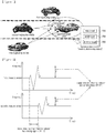
Figs. 2 and3 are for explaining who to determine a position in accordance with an embodiment of the present invention. -
Fig. 4 is a flow chart for explaining the operating of the position determining device in accordance with an embodiment of the present invention. - Hereinafter, an embodiment of the present invention will be described with reference to figures.
-
Fig. 1 is a diagram of a position determining device in accordance with an embodiment of the present invention. - As depicted in
Fig. 1 , a position determining device in accordance with an embodiment of the present invention may comprise a receiving unit (100) for receiving sensing signals from ultrasound sensors, a confirming unit (200) for confirming the receiving time and strengths of the sensing signals, and a determination unit (300) for determining a position of a neighboring vehicle on the basis of receiving time and strengths of each of the sensing signals. - The position determining device comprising the receiving unit (100), the confirming unit (200) and the determination unit (300) may be at least partly implemented in a form of a software module, a hardware module or any combination thereof.
- The position determining device in accordance with an embodiment of the present invention may be operated to determine a position of an approaching vehicle while driving a vehicle.
- Recently, a driver ends up operating additional operational instruments besides those for driving resulting in an increase of risk in driving due to driver inattention. As such, a safety device is required to prevent or avoid a vehicle collision on congested urban roads. To this end, conventional techniques determine a position of a neighboring vehicle by applying a position tracking algorithm using micro array sensors. For micro array sensors, although a plurality of sensors are applied in an array, not all sensing signals received from the plurality of sensors are used to determine the position of the neighboring vehicle, rather sensing signals received from only some of the plurality of sensors are used to determine the position of the neighboring vehicle. Consequently, this is very economically ineffective.
- However, in accordance with an embodiment of the present invention, it is possible to determine a position of a neighboring vehicle only by using two ultrasound sensors, as will be explained in detail. Hereinafter, the two ultrasound sensors for determining a position of the neighboring vehicle are referred to a first ultrasound sensor and a second ultrasound sensor, respectively. The first ultrasound sensor and the second ultrasound sensor are installed separated away from each other in a vehicle.
- The receiving unit (100) may receive sensing signals. The receiving unit (100) may receive a first sensing signal related to the neighboring vehicle from a first ultrasound sensor instal led in a vehicle and receive a second sensing signal related to the neighboring vehicle from a second ultrasound sensor installed at a position separated away from the first ultrasound sensor.
- The first sensing signal and the second sensing signal may be the ultrasound signals which are generated at the same time, reflected from the neighboring vehicle and then received. For this, the first ultrasound sensor and the second ultrasound sensor may be configured to generate ultrasound signals at the same time and receive their reflected signals. Alternatively, the first ultrasound sensor and the second ultrasound sensor may be configured to sense an ultrasound signal which is generated from a separate ultrasound generator at a specific point of time by having the separate ultrasound generator generating the ultrasound signal.
- The confirming unit (200) may confirm the receiving time and strengths of the sensing signals. If the first sensing signal and the second sensing signal are received via the receiving unit (100), the confirming unit (200) may confirm the receiving time and strengths of each of the first sensing signal and the second sensing signal. In particular, the confirming unit (200) may position each of the first sensing signal and the second sensing signal on a time-frequency plane to thereby confirm the receiving time and strengths of each of the first sensing signal and the second sensing signal.
- There may be a difference in the receiving time and strength of each of the first sensing signal and the second sensing signal as depicted in
Fig.2 for example. The difference in the receiving time and strength between the first sensing signal and the second sensing signal occurs because, due to the fact of that the first ultrasound sensor and the second ultrasound sensor are installed separated away from each other in a vehicle, the distance difference corresponding to the separation distance in receiving the ultrasound signals reflected from the neighboring vehicle occurs. - The confirming unit (200) may confirm the difference in the receiving time and strength of each of the first sensing signal and the second sensing signal by using a relative signal attenuation-time delay histogram which is generated with respect to one of the sensing signals on the basis of the other signal on the time-frequency plane as in depicted in
Fig. 3 , for example. - The determination unit (300) may determine a position of the neighboring vehicle. The determination unit (300) may determine a position of the neighboring vehicle on the basis of a difference in the receiving time and strength of each of the first sensing signal and the second sensing signal.
- In particular, the determination unit (300) may calculate a distance between the first ultrasound sensor and the neighboring vehicle and a distance between the second ultrasound sensor and the neighboring vehicle on the basis of receiving time and strengths of each of the first sensing signal and the second sensing signal. In addition, the determination unit (300) may determine a position of the neighboring vehicle on the basis of the two calculated distances and the separation distance between the first ultrasound sensor and the second ultrasound sensor.
- For example, the determination unit (300) may form a triangle consisting of a straight line corresponding to the calculated distance between the first ultrasound sensor and the neighboring vehicle, a straight line corresponding to the calculated distance between the second ultrasound sensor and the neighboring vehicle and a straight line corresponding to the separation distance between the first ultrasound sensor and the second ultrasound sensor. Then, the determination unit (300) may determine the other vertex rather than two vertexes corresponding to the first ultrasound sensor and the second ultrasound sensor as a position of the neighboring vehicle.
- The difference in the receiving time and strength of each of the first sensing signal and the second sensing signal represents a distance difference of the distance between the first ultrasound sensor and the neighboring vehicle from the distance between the second ultrasound sensor and the neighboring vehicle.
- Accordingly, the determination unit (300) can specifically determine a position of the neighboring vehicle by using the distance difference of the distance between the first ultrasound sensor and the neighboring vehicle from the distance between the second ultrasound sensor and the neighboring vehicle, in addition to the separation distance between the first ultrasound sensor and the second ultrasound sensor.
- The difference in the receiving time and the difference in strength between the first sensing signal and the second sensing signal may change in sequence of '(a)' -> '(b)' as depicted in
Fig. 3 as the neighbor ing vehicle moves. Accordingly, the confirming unit (200) may periodically confirm the difference in the receiving time and the difference in strength between the first sensing signal and the second sensing signal. In this case, the determination unit (300) may periodically determine the changing position of the neighboring vehicle by using the periodically confirmed differences. Thus, it is possible to send an alarm to the driver or show the change of the position of the neighboring vehicle over time. - In accordance with a position determining device of the present invention, a position of a neighboring vehicle can be determined by using the differences of the receiving time and strengths between two sensing signals received from two ultrasound sensors installed in a vehicle. Therefore, it is possible to estimate a position and a moving path for neighboring vehicles while driving a vehicle.
- Hereinafter, an operating method of a position determining device in accordance with an embodiment of the present invention will be described with reference to
figure 4 . The same reference numerals are used to designate the same elements as those inFig. 1 . - First, it is performed receiving a first sensing signal related to the neighboring vehicle from a first ultrasound sensor installed in a vehicle and receiving a second sensing signal related to the neighboring vehicle from a second ultrasound sensor installed at a position separated away from the first ultrasound sensor (S100). The first sensing signal and the second sensing signal may be the ultrasound signals which are generated at the same time, reflected from the neighboring vehicle and then received. For this, the first ultrasound sensor and the second ultrasound sensor may be configured to generate ultrasound signals at the same time and receive their reflected signals.
- Next, the confirming unit (200) may confirm the receiving time and strengths of each of the first sensing signal and the second sensing signal if the first sensing signal and the second sensing signal are received via the receiving unit (100)(S200). The confirming unit (200) may position each of the first sensing signal and the second sensing signal on a time-frequency plane to thereby confirm the receiving time and strengths of each of the first sensing signal and the second sensing signal.
- In addition, the confirming unit (200) may confirm the difference in the receiving time and strength of each of the first sensing signal and the second sensing signal (S300). In this case, the confirming unit (200) may confirm the difference in the receiving time and strength between the first sensing signal and the second sensing signal by using a relative signal attenuation-time delay histogram which is generated with respect to one of the sensing signals on the basis of the other signal on the time-frequency plane.
- Next, the determination unit (300) may determine a position of the neighboring vehicle on the basis of a difference in the receiving time and strength of each of the first sensing signal and the second sensing signal (S400).
- In particular, the determination unit (300) may calculate a distance between the first ultrasound sensor and the neighboring vehicle and a distance between the second ultrasound sensor and the neighboring vehicle on the basis of receiving time and strengths of each of the first sensing signal and the second sensing signal. In addition, the determination unit (300) may determine a position of the neighboring vehicle on the basis of the two calculated distances and the separation distance between the first ultrasound sensor and the second ultrasound sensor.
- The confirming unit (200) may periodically confirm the difference in the receiving time and the difference in strength between the first sensing signal and the second sensing signal. In this case, the determination unit (300) may periodically determine the changing position of the neighboring vehicle by using the periodically confirmed differences. Thus, it is possible to send an alarm to the driver or show the change of the position of the neighboring vehicle over time (S500).
- In accordance with a method of operating a position determining device of the present invention, a position of a neighboring vehicle can be determined by using the differences of the receiving time and strengths between two sensing signals received from two ultrasound sensors installed in a vehicle. Therefore, it is possible to estimate a position and a moving path for neighboring vehicles while driving a vehicle.
- Implementations of the functional operations and subject matter described herein may be realized by digital electronic circuitry, computer software, firmware or hardware including the structures described herein and structural equivalents thereof, or a combination of one or more thereof. Implementations of the subject matter described herein may be implemented as one or more computer program products, that is, one or more modules related to computer program instructions encoded on a tangible program storage medium to control an operation of a processing system or to execute it by the computer program instructions.
- Although the operations are illustrated in a particular order in the present disclosure, it is not to be understood that the operations should be sequentially performed according to such order or that all the operations illustrated should be performed, in order to acquire a preferred result. In a particular case, multi-tasking and parallel processing may be advantageous. Further, it should not be understood that the separation of various system components in the above embodiments is required in all embodiments, and it should be noted that the program component and systems may be generally integrated into a single software product or may be packaged into multiple software products.
- Thus, the present disclosure is not intended to limit the invention to the specific terms set forth. Although exemplary embodiments of the present invention have been described for illustrative purposes, those skilled in the art will appreciate that various modifications, additions and substitutions are possible, without departing from the essential features and the scope and spirit of the invention as disclosed in the accompanying claims. Therefore, it should be appreciated that the embodiments described above are not limitative, but only illustrative.
Claims (9)
- A position determining device for determining a position of a neighboring vehicle, comprising:a receiving unit for receiving a first sensing signal related to the neighboring vehicle from a first ultrasound sensor installed in a vehicle and receiving a second sensing signal related to the neighboring vehicle from a second ultrasound sensor installed at a position separated away from the first ultrasound sensor; anda determination unit for determining the position of the neighboring vehicle on the basis of receiving time and strengths of each of the first sensing signal and the second sensing signal.
- The position determining device for determining a position of a neighboring vehicle according to claim 1,
wherein the position determining device further comprises a confirming unit for confirming the receiving time and strengths of each of the first sensing signal and the second sensing signal, and
wherein the confirming unit positions each of the first sensing signal and the second sensing signal on a time-frequency plane to thereby confirm the receiving time and strengths of each of the first sensing signal and the second sensing signal. - The position determining device for determining a position of a neighboring vehicle according to claim 2, wherein the determination unit determines a position of the neighboring vehicle on the basis of a difference in the receiving time and strength of each of the first sensing signal and the second sensing signal.
- The position determining device for determining a position of a neighboring vehicle according to claim 3, wherein the difference in the receiving time and strength of each of the first sensing signal and the second sensing signal is confirmed from a relative signal attenuation-time delay histogram which is generated with respect to one signal of the first and the second sensing signals on the basis of the other signal thereof on the time-frequency plane.
- A method of operating a position determining device for determining a position of a neighboring vehicle, comprising the steps of:receiving a first sensing signal related to the neighboring vehicle from a first ultrasound sensor installed in a vehicle and receiving a second sensing signal related to the neighboring vehicle from a second ultrasound sensor installed at a position separated away from the first ultrasound sensor; anddetermining the position of the neighboring vehicle on the basis of receiving time and strengths of each of the first sensing signal and the second sensing signal.
- The method of operating a position determining device for determining a position of a neighboring vehicle according to claim 5,
wherein the method further comprises confirming the receiving time and strengths of each of the first sensing signal and the second sensing signal, and
wherein the step of confirming positions each of the first sensing signal and the second sensing signal on a time-frequency plane to thereby confirm the receiving time and strengths of each of the first sensing signal and the second sensing signal. - The method of operating a position determining device for determining a position of a neighboring vehicle according to claim 6, wherein the step of determining determines a position of the neighboring vehicle on the basis of a difference in the receiving time and strength of each of the first sensing signal and the second sensing signal.
- The method of operating a position determining device for determining a position of a neighboring vehicle according to claim 7, wherein the difference in the receiving time and strength of each of the first sensing signal and the second sensing signal is confirmed from a relative signal attenuation-time delay histogram which is generated with respect to one signal of the first and the second sensing signals on the basis of the other signal thereof on the time-frequency plane.
- A computer program stored in a medium for executing the steps of:receiving a first sensing signal relating to a neighboring vehicle from a first ultrasound sensor installed in a vehicle and receiving a second sensing signal related to the neighboring vehicle from a second ultrasound sensor instal led at a position separated away from the first ultrasound sensor; anddetermining the position of the neighboring vehicle on the basis of receiving time and strengths of each of the first sensing signal and the second sensing signal.
Applications Claiming Priority (2)
| Application Number | Priority Date | Filing Date | Title |
|---|---|---|---|
| KR1020140149722A KR101528595B1 (en) | 2014-10-31 | 2014-10-31 | Apparatus for location detecting and control method thereof |
| PCT/KR2015/011596 WO2016068657A1 (en) | 2014-10-31 | 2015-10-30 | Location determination device and method for operating same |
Publications (2)
| Publication Number | Publication Date |
|---|---|
| EP3214459A1 true EP3214459A1 (en) | 2017-09-06 |
| EP3214459B1 EP3214459B1 (en) | 2025-08-20 |
Family
ID=53503743
Family Applications (1)
| Application Number | Title | Priority Date | Filing Date |
|---|---|---|---|
| EP15855785.0A Active EP3214459B1 (en) | 2014-10-31 | 2015-10-30 | Location determination device and method for operating same |
Country Status (6)
| Country | Link |
|---|---|
| US (1) | US10515545B2 (en) |
| EP (1) | EP3214459B1 (en) |
| JP (1) | JP2018502277A (en) |
| KR (1) | KR101528595B1 (en) |
| CN (1) | CN107003396A (en) |
| WO (1) | WO2016068657A1 (en) |
Families Citing this family (3)
| Publication number | Priority date | Publication date | Assignee | Title |
|---|---|---|---|---|
| CN117533173A (en) * | 2023-11-07 | 2024-02-09 | 中车株洲电力机车有限公司 | Tramcar parking control system and method |
| CN118386758B (en) * | 2024-06-25 | 2024-09-13 | 江西科技学院 | Intelligent automobile suspension control system |
| US20260160871A1 (en) * | 2024-12-09 | 2026-06-11 | Valeo Schalter Und Sensoren Gmbh | Occupancy grid based dynamic firing of ultrasonic sensors |
Family Cites Families (16)
| Publication number | Priority date | Publication date | Assignee | Title |
|---|---|---|---|---|
| JPS6064273A (en) * | 1983-09-20 | 1985-04-12 | Oki Electric Ind Co Ltd | Target position detecting system |
| KR100246063B1 (en) * | 1997-12-10 | 2000-05-01 | 배길훈 | Car Rear Safety Inspection Method |
| JP2002372577A (en) * | 2001-06-14 | 2002-12-26 | Matsushita Electric Works Ltd | Obstacle detection device |
| JP4396400B2 (en) * | 2004-06-02 | 2010-01-13 | トヨタ自動車株式会社 | Obstacle recognition device |
| CN100514084C (en) * | 2007-09-18 | 2009-07-15 | 澳门科技大学 | Positioning method and device for radio frequency identification system |
| CN101526601B (en) * | 2008-03-04 | 2013-02-13 | 日电(中国)有限公司 | Self-adaptive localization method, equipment and system adopting TOA and RSS fusion mode |
| KR101585460B1 (en) * | 2009-03-12 | 2016-01-15 | 엘지전자 주식회사 | Mobile terminal and inputing method for mobile terminal |
| KR20110012584A (en) * | 2009-07-31 | 2011-02-09 | 삼성전자주식회사 | Ultrasonic Based 3D Position Estimation Apparatus and Method |
| DE102009028992A1 (en) * | 2009-08-28 | 2011-03-03 | Robert Bosch Gmbh | Method and device for determining the position of an obstacle relative to a vehicle, in particular a motor vehicle, for use in a driver assistance system of the vehicle |
| DE102009029465A1 (en) * | 2009-09-15 | 2011-04-21 | Robert Bosch Gmbh | Method for determining e.g. relative speed of object to assist driver of vehicle during parking, involves determining speed vector, speed and motion direction of object from calculated distances, speed components, angles and perpendiculars |
| JP2011174735A (en) * | 2010-02-23 | 2011-09-08 | Toshiba Alpine Automotive Technology Corp | Driving support apparatus and obstacle detection method |
| DE102010045657A1 (en) | 2010-09-17 | 2012-03-22 | Wabco Gmbh | Environment monitoring system for a vehicle |
| KR20120119420A (en) * | 2011-04-21 | 2012-10-31 | 한국전자통신연구원 | Apparatus and method for intelligently controlling moving object |
| JP2013205204A (en) * | 2012-03-28 | 2013-10-07 | Mitsubishi Electric Corp | Obstacle detection device |
| DE102012212894A1 (en) * | 2012-07-24 | 2014-01-30 | Robert Bosch Gmbh | Method for operating an environment detection system of a vehicle with at least two transceiver units and environment detection system |
| CN103442434B (en) | 2013-08-20 | 2016-03-02 | 京信通信系统(中国)有限公司 | A kind of personnel positioning method, Apparatus and system be applied in tunnel environment |
-
2014
- 2014-10-31 KR KR1020140149722A patent/KR101528595B1/en active Active
-
2015
- 2015-10-30 WO PCT/KR2015/011596 patent/WO2016068657A1/en not_active Ceased
- 2015-10-30 EP EP15855785.0A patent/EP3214459B1/en active Active
- 2015-10-30 CN CN201580059166.3A patent/CN107003396A/en active Pending
- 2015-10-30 US US15/520,246 patent/US10515545B2/en active Active
- 2015-10-30 JP JP2017522863A patent/JP2018502277A/en active Pending
Also Published As
| Publication number | Publication date |
|---|---|
| KR101528595B1 (en) | 2015-06-12 |
| JP2018502277A (en) | 2018-01-25 |
| US20170365167A1 (en) | 2017-12-21 |
| WO2016068657A1 (en) | 2016-05-06 |
| EP3214459B1 (en) | 2025-08-20 |
| US10515545B2 (en) | 2019-12-24 |
| CN107003396A (en) | 2017-08-01 |
Similar Documents
| Publication | Publication Date | Title |
|---|---|---|
| US11002849B2 (en) | Driving lane detection device and driving lane detection method | |
| US10101168B2 (en) | Route calculation device for vehicle | |
| JP6224370B2 (en) | Vehicle controller, vehicle system | |
| US10625739B2 (en) | Vehicle control apparatus and vehicle control method | |
| JP5919328B2 (en) | Vehicle collision warning device and vehicle collision warning method | |
| CN102959600B (en) | Device for estimating vehicle travel path | |
| KR101843073B1 (en) | Driving assistance device for vehicles and onboard computer | |
| JP5968064B2 (en) | Traveling lane recognition device and traveling lane recognition method | |
| CN104364832B (en) | Model-following control device | |
| JP2017520056A (en) | Road bifurcation detection method and route selection method for lane centering | |
| EP2784762A1 (en) | Vehicle identification device | |
| CN111352074B (en) | Method and system for localizing a sound source relative to a vehicle | |
| GB2484794A (en) | Determining a restricted detection range of a sensor of a vehicle | |
| EP3499483A1 (en) | Object detection device and vehicle control system comprising object detection device | |
| WO2022130720A1 (en) | Dividing line recognition device | |
| US7557907B2 (en) | Object-detection device for vehicle | |
| CN112462750A (en) | Vehicle control device, vehicle control method, and storage medium | |
| EP3214459B1 (en) | Location determination device and method for operating same | |
| US20120268310A1 (en) | Apparatus and method for intelligently controlling moving object | |
| JP2018179926A (en) | Object recognition processing apparatus, object recognition processing method, and vehicle control system | |
| JP5163087B2 (en) | Object detection device | |
| WO2019078211A1 (en) | Moving object recognition device | |
| JP2009075650A (en) | Collision determination device | |
| JP2018502277A5 (en) | ||
| JP5783163B2 (en) | Target detection device |
Legal Events
| Date | Code | Title | Description |
|---|---|---|---|
| STAA | Information on the status of an ep patent application or granted ep patent |
Free format text: STATUS: THE INTERNATIONAL PUBLICATION HAS BEEN MADE |
|
| PUAI | Public reference made under article 153(3) epc to a published international application that has entered the european phase |
Free format text: ORIGINAL CODE: 0009012 |
|
| STAA | Information on the status of an ep patent application or granted ep patent |
Free format text: STATUS: REQUEST FOR EXAMINATION WAS MADE |
|
| 17P | Request for examination filed |
Effective date: 20170531 |
|
| AK | Designated contracting states |
Kind code of ref document: A1 Designated state(s): AL AT BE BG CH CY CZ DE DK EE ES FI FR GB GR HR HU IE IS IT LI LT LU LV MC MK MT NL NO PL PT RO RS SE SI SK SM TR |
|
| AX | Request for extension of the european patent |
Extension state: BA ME |
|
| DAV | Request for validation of the european patent (deleted) | ||
| DAX | Request for extension of the european patent (deleted) | ||
| R17P | Request for examination filed (corrected) |
Effective date: 20170531 |
|
| RAP1 | Party data changed (applicant data changed or rights of an application transferred) |
Owner name: CONTINENTAL AUTOMOTIVE GMBH |
|
| STAA | Information on the status of an ep patent application or granted ep patent |
Free format text: STATUS: EXAMINATION IS IN PROGRESS |
|
| 17Q | First examination report despatched |
Effective date: 20210709 |
|
| RAP1 | Party data changed (applicant data changed or rights of an application transferred) |
Owner name: CONTINENTAL AUTONOMOUS MOBILITY GERMANY GMBH |
|
| GRAP | Despatch of communication of intention to grant a patent |
Free format text: ORIGINAL CODE: EPIDOSNIGR1 |
|
| STAA | Information on the status of an ep patent application or granted ep patent |
Free format text: STATUS: GRANT OF PATENT IS INTENDED |
|
| INTG | Intention to grant announced |
Effective date: 20250326 |
|
| GRAS | Grant fee paid |
Free format text: ORIGINAL CODE: EPIDOSNIGR3 |
|
| GRAA | (expected) grant |
Free format text: ORIGINAL CODE: 0009210 |
|
| STAA | Information on the status of an ep patent application or granted ep patent |
Free format text: STATUS: THE PATENT HAS BEEN GRANTED |
|
| RAP3 | Party data changed (applicant data changed or rights of an application transferred) |
Owner name: AUMOVIO AUTONOMOUS MOBILITY GERMANY GMBH |
|
| AK | Designated contracting states |
Kind code of ref document: B1 Designated state(s): AL AT BE BG CH CY CZ DE DK EE ES FI FR GB GR HR HU IE IS IT LI LT LU LV MC MK MT NL NO PL PT RO RS SE SI SK SM TR |
|
| REG | Reference to a national code |
Ref country code: GB Ref legal event code: FG4D |
|
| REG | Reference to a national code |
Ref country code: CH Ref legal event code: EP |
|
| REG | Reference to a national code |
Ref country code: IE Ref legal event code: FG4D |
|
| REG | Reference to a national code |
Ref country code: DE Ref legal event code: R096 Ref document number: 602015092222 Country of ref document: DE |
|
| REG | Reference to a national code |
Ref country code: NL Ref legal event code: MP Effective date: 20250820 |
|
| PG25 | Lapsed in a contracting state [announced via postgrant information from national office to epo] |
Ref country code: IS Free format text: LAPSE BECAUSE OF FAILURE TO SUBMIT A TRANSLATION OF THE DESCRIPTION OR TO PAY THE FEE WITHIN THE PRESCRIBED TIME-LIMIT Effective date: 20251220 |
|
| PGFP | Annual fee paid to national office [announced via postgrant information from national office to epo] |
Ref country code: DE Payment date: 20251031 Year of fee payment: 11 |
|
| PGFP | Annual fee paid to national office [announced via postgrant information from national office to epo] |
Ref country code: GB Payment date: 20251021 Year of fee payment: 11 |
|
| PG25 | Lapsed in a contracting state [announced via postgrant information from national office to epo] |
Ref country code: NO Free format text: LAPSE BECAUSE OF FAILURE TO SUBMIT A TRANSLATION OF THE DESCRIPTION OR TO PAY THE FEE WITHIN THE PRESCRIBED TIME-LIMIT Effective date: 20251120 |
|
| REG | Reference to a national code |
Ref country code: LT Ref legal event code: MG9D |
|
| PG25 | Lapsed in a contracting state [announced via postgrant information from national office to epo] |
Ref country code: PT Free format text: LAPSE BECAUSE OF FAILURE TO SUBMIT A TRANSLATION OF THE DESCRIPTION OR TO PAY THE FEE WITHIN THE PRESCRIBED TIME-LIMIT Effective date: 20251222 |
|
| PG25 | Lapsed in a contracting state [announced via postgrant information from national office to epo] |
Ref country code: FI Free format text: LAPSE BECAUSE OF FAILURE TO SUBMIT A TRANSLATION OF THE DESCRIPTION OR TO PAY THE FEE WITHIN THE PRESCRIBED TIME-LIMIT Effective date: 20250820 |
|
| PG25 | Lapsed in a contracting state [announced via postgrant information from national office to epo] |
Ref country code: NL Free format text: LAPSE BECAUSE OF FAILURE TO SUBMIT A TRANSLATION OF THE DESCRIPTION OR TO PAY THE FEE WITHIN THE PRESCRIBED TIME-LIMIT Effective date: 20250820 Ref country code: HR Free format text: LAPSE BECAUSE OF FAILURE TO SUBMIT A TRANSLATION OF THE DESCRIPTION OR TO PAY THE FEE WITHIN THE PRESCRIBED TIME-LIMIT Effective date: 20250820 |
|
| PG25 | Lapsed in a contracting state [announced via postgrant information from national office to epo] |
Ref country code: GR Free format text: LAPSE BECAUSE OF FAILURE TO SUBMIT A TRANSLATION OF THE DESCRIPTION OR TO PAY THE FEE WITHIN THE PRESCRIBED TIME-LIMIT Effective date: 20251121 |
|
| PG25 | Lapsed in a contracting state [announced via postgrant information from national office to epo] |
Ref country code: SE Free format text: LAPSE BECAUSE OF FAILURE TO SUBMIT A TRANSLATION OF THE DESCRIPTION OR TO PAY THE FEE WITHIN THE PRESCRIBED TIME-LIMIT Effective date: 20250820 |
|
| PG25 | Lapsed in a contracting state [announced via postgrant information from national office to epo] |
Ref country code: LV Free format text: LAPSE BECAUSE OF FAILURE TO SUBMIT A TRANSLATION OF THE DESCRIPTION OR TO PAY THE FEE WITHIN THE PRESCRIBED TIME-LIMIT Effective date: 20250820 |
|
| PG25 | Lapsed in a contracting state [announced via postgrant information from national office to epo] |
Ref country code: PL Free format text: LAPSE BECAUSE OF FAILURE TO SUBMIT A TRANSLATION OF THE DESCRIPTION OR TO PAY THE FEE WITHIN THE PRESCRIBED TIME-LIMIT Effective date: 20250820 Ref country code: BG Free format text: LAPSE BECAUSE OF FAILURE TO SUBMIT A TRANSLATION OF THE DESCRIPTION OR TO PAY THE FEE WITHIN THE PRESCRIBED TIME-LIMIT Effective date: 20250820 |
|
| PG25 | Lapsed in a contracting state [announced via postgrant information from national office to epo] |
Ref country code: RS Free format text: LAPSE BECAUSE OF FAILURE TO SUBMIT A TRANSLATION OF THE DESCRIPTION OR TO PAY THE FEE WITHIN THE PRESCRIBED TIME-LIMIT Effective date: 20251120 |
|
| PG25 | Lapsed in a contracting state [announced via postgrant information from national office to epo] |
Ref country code: ES Free format text: LAPSE BECAUSE OF FAILURE TO SUBMIT A TRANSLATION OF THE DESCRIPTION OR TO PAY THE FEE WITHIN THE PRESCRIBED TIME-LIMIT Effective date: 20250820 |
|
| REG | Reference to a national code |
Ref country code: AT Ref legal event code: MK05 Ref document number: 1827857 Country of ref document: AT Kind code of ref document: T Effective date: 20250820 |
|
| PG25 | Lapsed in a contracting state [announced via postgrant information from national office to epo] |
Ref country code: RO Free format text: LAPSE BECAUSE OF FAILURE TO SUBMIT A TRANSLATION OF THE DESCRIPTION OR TO PAY THE FEE WITHIN THE PRESCRIBED TIME-LIMIT Effective date: 20250820 |
|
| PG25 | Lapsed in a contracting state [announced via postgrant information from national office to epo] |
Ref country code: SM Free format text: LAPSE BECAUSE OF FAILURE TO SUBMIT A TRANSLATION OF THE DESCRIPTION OR TO PAY THE FEE WITHIN THE PRESCRIBED TIME-LIMIT Effective date: 20250820 |
|
| PG25 | Lapsed in a contracting state [announced via postgrant information from national office to epo] |
Ref country code: DK Free format text: LAPSE BECAUSE OF FAILURE TO SUBMIT A TRANSLATION OF THE DESCRIPTION OR TO PAY THE FEE WITHIN THE PRESCRIBED TIME-LIMIT Effective date: 20250820 |
|
| PG25 | Lapsed in a contracting state [announced via postgrant information from national office to epo] |
Ref country code: AT Free format text: LAPSE BECAUSE OF FAILURE TO SUBMIT A TRANSLATION OF THE DESCRIPTION OR TO PAY THE FEE WITHIN THE PRESCRIBED TIME-LIMIT Effective date: 20250820 |
|
| PG25 | Lapsed in a contracting state [announced via postgrant information from national office to epo] |
Ref country code: IT Free format text: LAPSE BECAUSE OF FAILURE TO SUBMIT A TRANSLATION OF THE DESCRIPTION OR TO PAY THE FEE WITHIN THE PRESCRIBED TIME-LIMIT Effective date: 20250820 |
|
| PG25 | Lapsed in a contracting state [announced via postgrant information from national office to epo] |
Ref country code: CZ Free format text: LAPSE BECAUSE OF FAILURE TO SUBMIT A TRANSLATION OF THE DESCRIPTION OR TO PAY THE FEE WITHIN THE PRESCRIBED TIME-LIMIT Effective date: 20250820 |
|
| PG25 | Lapsed in a contracting state [announced via postgrant information from national office to epo] |
Ref country code: EE Free format text: LAPSE BECAUSE OF FAILURE TO SUBMIT A TRANSLATION OF THE DESCRIPTION OR TO PAY THE FEE WITHIN THE PRESCRIBED TIME-LIMIT Effective date: 20250820 Ref country code: SK Free format text: LAPSE BECAUSE OF FAILURE TO SUBMIT A TRANSLATION OF THE DESCRIPTION OR TO PAY THE FEE WITHIN THE PRESCRIBED TIME-LIMIT Effective date: 20250820 |
|
| REG | Reference to a national code |
Ref country code: DE Ref legal event code: R097 Ref document number: 602015092222 Country of ref document: DE |
|
| REG | Reference to a national code |
Ref country code: CH Ref legal event code: H13 Free format text: ST27 STATUS EVENT CODE: U-0-0-H10-H13 (AS PROVIDED BY THE NATIONAL OFFICE) Effective date: 20260527 |
|
| PG25 | Lapsed in a contracting state [announced via postgrant information from national office to epo] |
Ref country code: LU Free format text: LAPSE BECAUSE OF NON-PAYMENT OF DUE FEES Effective date: 20251030 |
|
| REG | Reference to a national code |
Ref country code: BE Ref legal event code: MM Effective date: 20251031 |
|
| PLBE | No opposition filed within time limit |
Free format text: ORIGINAL CODE: 0009261 |
|
| STAA | Information on the status of an ep patent application or granted ep patent |
Free format text: STATUS: NO OPPOSITION FILED WITHIN TIME LIMIT |
|
| PG25 | Lapsed in a contracting state [announced via postgrant information from national office to epo] |
Ref country code: LT Free format text: LAPSE BECAUSE OF FAILURE TO SUBMIT A TRANSLATION OF THE DESCRIPTION OR TO PAY THE FEE WITHIN THE PRESCRIBED TIME-LIMIT Effective date: 20250820 Ref country code: MC Free format text: LAPSE BECAUSE OF FAILURE TO SUBMIT A TRANSLATION OF THE DESCRIPTION OR TO PAY THE FEE WITHIN THE PRESCRIBED TIME-LIMIT Effective date: 20250820 |
|
| REG | Reference to a national code |
Ref country code: CH Ref legal event code: L10 Free format text: ST27 STATUS EVENT CODE: U-0-0-L10-L00 (AS PROVIDED BY THE NATIONAL OFFICE) Effective date: 20260701 |
|
| PG25 | Lapsed in a contracting state [announced via postgrant information from national office to epo] |
Ref country code: BE Free format text: LAPSE BECAUSE OF NON-PAYMENT OF DUE FEES Effective date: 20251031 Ref country code: CH Free format text: LAPSE BECAUSE OF NON-PAYMENT OF DUE FEES Effective date: 20251031 |
|
| PG25 | Lapsed in a contracting state [announced via postgrant information from national office to epo] |
Ref country code: FR Free format text: LAPSE BECAUSE OF NON-PAYMENT OF DUE FEES Effective date: 20251031 |
|
| 26N | No opposition filed |
Effective date: 20260521 |