EP3214417A1 - Apparatus and method for monitoring water level within pipe - Google Patents
Apparatus and method for monitoring water level within pipe Download PDFInfo
- Publication number
- EP3214417A1 EP3214417A1 EP14904787.0A EP14904787A EP3214417A1 EP 3214417 A1 EP3214417 A1 EP 3214417A1 EP 14904787 A EP14904787 A EP 14904787A EP 3214417 A1 EP3214417 A1 EP 3214417A1
- Authority
- EP
- European Patent Office
- Prior art keywords
- ultrasonic
- pipe
- water level
- waves
- reflective
- Prior art date
- Legal status (The legal status is an assumption and is not a legal conclusion. Google has not performed a legal analysis and makes no representation as to the accuracy of the status listed.)
- Granted
Links
Images



Classifications
-
- G—PHYSICS
- G01—MEASURING; TESTING
- G01F—MEASURING VOLUME, VOLUME FLOW, MASS FLOW OR LIQUID LEVEL; METERING BY VOLUME
- G01F23/00—Indicating or measuring liquid level or level of fluent solid material, e.g. indicating in terms of volume or indicating by means of an alarm
- G01F23/22—Indicating or measuring liquid level or level of fluent solid material, e.g. indicating in terms of volume or indicating by means of an alarm by measuring physical variables, other than linear dimensions, pressure or weight, dependent on the level to be measured, e.g. by difference of heat transfer of steam or water
- G01F23/28—Indicating or measuring liquid level or level of fluent solid material, e.g. indicating in terms of volume or indicating by means of an alarm by measuring physical variables, other than linear dimensions, pressure or weight, dependent on the level to be measured, e.g. by difference of heat transfer of steam or water by measuring the variations of parameters of electromagnetic or acoustic waves applied directly to the liquid or fluent solid material
- G01F23/296—Acoustic waves
-
- G—PHYSICS
- G01—MEASURING; TESTING
- G01F—MEASURING VOLUME, VOLUME FLOW, MASS FLOW OR LIQUID LEVEL; METERING BY VOLUME
- G01F23/00—Indicating or measuring liquid level or level of fluent solid material, e.g. indicating in terms of volume or indicating by means of an alarm
- G01F23/22—Indicating or measuring liquid level or level of fluent solid material, e.g. indicating in terms of volume or indicating by means of an alarm by measuring physical variables, other than linear dimensions, pressure or weight, dependent on the level to be measured, e.g. by difference of heat transfer of steam or water
- G01F23/28—Indicating or measuring liquid level or level of fluent solid material, e.g. indicating in terms of volume or indicating by means of an alarm by measuring physical variables, other than linear dimensions, pressure or weight, dependent on the level to be measured, e.g. by difference of heat transfer of steam or water by measuring the variations of parameters of electromagnetic or acoustic waves applied directly to the liquid or fluent solid material
- G01F23/296—Acoustic waves
- G01F23/2961—Acoustic waves for discrete levels
-
- G—PHYSICS
- G01—MEASURING; TESTING
- G01N—INVESTIGATING OR ANALYSING MATERIALS BY DETERMINING THEIR CHEMICAL OR PHYSICAL PROPERTIES
- G01N29/00—Investigating or analysing materials by the use of ultrasonic, sonic or infrasonic waves; Visualisation of the interior of objects by transmitting ultrasonic or sonic waves through the object
- G01N29/02—Analysing fluids
- G01N29/024—Analysing fluids by measuring propagation velocity or propagation time of acoustic waves
-
- G—PHYSICS
- G01—MEASURING; TESTING
- G01N—INVESTIGATING OR ANALYSING MATERIALS BY DETERMINING THEIR CHEMICAL OR PHYSICAL PROPERTIES
- G01N29/00—Investigating or analysing materials by the use of ultrasonic, sonic or infrasonic waves; Visualisation of the interior of objects by transmitting ultrasonic or sonic waves through the object
- G01N29/02—Analysing fluids
- G01N29/032—Analysing fluids by measuring attenuation of acoustic waves
-
- G—PHYSICS
- G01—MEASURING; TESTING
- G01N—INVESTIGATING OR ANALYSING MATERIALS BY DETERMINING THEIR CHEMICAL OR PHYSICAL PROPERTIES
- G01N29/00—Investigating or analysing materials by the use of ultrasonic, sonic or infrasonic waves; Visualisation of the interior of objects by transmitting ultrasonic or sonic waves through the object
- G01N29/22—Details, e.g. general constructional or apparatus details
-
- G—PHYSICS
- G01—MEASURING; TESTING
- G01S—RADIO DIRECTION-FINDING; RADIO NAVIGATION; DETERMINING DISTANCE OR VELOCITY BY USE OF RADIO WAVES; LOCATING OR PRESENCE-DETECTING BY USE OF THE REFLECTION OR RERADIATION OF RADIO WAVES; ANALOGOUS ARRANGEMENTS USING OTHER WAVES
- G01S15/00—Systems using the reflection or reradiation of acoustic waves, e.g. sonar systems
- G01S15/88—Sonar systems specially adapted for specific applications
-
- G—PHYSICS
- G08—SIGNALLING
- G08B—SIGNALLING SYSTEMS, e.g. PERSONAL CALLING SYSTEMS; ORDER TELEGRAPHS; ALARM SYSTEMS
- G08B21/00—Alarms responsive to a single specified undesired or abnormal condition and not otherwise provided for
- G08B21/18—Status alarms
-
- G—PHYSICS
- G08—SIGNALLING
- G08B—SIGNALLING SYSTEMS, e.g. PERSONAL CALLING SYSTEMS; ORDER TELEGRAPHS; ALARM SYSTEMS
- G08B21/00—Alarms responsive to a single specified undesired or abnormal condition and not otherwise provided for
- G08B21/18—Status alarms
- G08B21/182—Level alarms, e.g. alarms responsive to variables exceeding a threshold
Definitions
- the present invention relates to an apparatus and method for monitoring a water level within a pipe and, more particularly, to an apparatus and method for monitoring a water level within a pipe in a nondestructive manner using the examination of ultrasonic waves and multiple channels.
- a gas accumulation phenomenon within a pipe of a safety-related system is emerging as a pending issue related to the safety of local and international power plants.
- a safety pending issue has been known to make it difficult to perform the safety function of a safety-related system in the power plant and also to cause a severe accident.
- a method for monitoring a water level within a pipe which is capable of monitoring a water level within a pipe or a gas accumulation tendency.
- methods for measuring a water level within a pipe include methods for measuring a water level using differential pressure or through the direct modification or improvement of the system, such as installing a water level system within a pipe.
- a prior art includes Utility Model No. 200181636 (Device for detecting the water level of water seal valve).
- Utility Model No. 200181636 Device for detecting the water level of water seal valve.
- Such methods are inevitably accompanied by a process of dissembling a system or newly constructing a system in order to measure a water level within a pipe.
- a phenomenon related to the accumulation of gas within a pipe of a safety-related system is an important part from a viewpoint of the safety of a power plant. Accordingly, there is a need for a nondestructive and smooth method for monitoring a water level, which does not directly change a system.
- An object of the present invention is to provide an apparatus and method for monitoring a water level within a pipe in a nondestructive manner using the examination of ultrasonic waves and multiple channels.
- Another object of the present invention is to provide an apparatus and method, which are capable of performing the monitoring of a gas accumulation phenomenon and the monitoring of a water level within a pipe without a direct change in the safety-related system of a nuclear power plant.
- Yet another object of the present invention is to provide an apparatus and method for preventing the excessive accumulation of air within a pipe in a safety-related system, enhancing the safety of a power plant, and constructing a corresponding database by monitoring a water level within the pipe without changing the pipe.
- a system for monitoring a water level within a pipe includes an ultrasonic generation unit including at least one ultrasonic transducer which is disposed at spaced locations on the outside of the pipe and generates an ultrasonic wave, a solid contact medium which is provided on one side of the at least one ultrasonic transducer and brings the at least one ultrasonic transducer into contact with the outside of the pipe, and a support unit which supports the at least one ultrasonic transducer so that the transducer fixedly comes into contact with the outside of the pipe, an ultrasonic examination unit which controls the generation of the ultrasonic wave by driving the at least one ultrasonic transducer, detects the reflective wave of the ultrasonic wave, collects information about the reflective wave, and inputs/outputs the information, and a data processing unit which determines a water level based on the information about the reflective wave and processes or stores the information about the water level.
- an ultrasonic generation unit including at least one ultrasonic transducer which is disposed at spaced locations on the outside of the
- a plurality of ranges may be formed by a cross section of the pipe, based on a disposition of the at least one ultrasonic transducer in a vertical direction on the outside of the pipe, and the data processing unit may determine a range which belongs to the plurality of ranges and to which the water level belongs.
- the number of the at least one ultrasonic transducer may be 3, a first to third ultrasonic transducers may be sequentially disposed from the highest level to the lower side along the outside of the pipe, and the plurality of ranges may include a normal range, a warning range, and a danger range.
- the data processing unit may determine that the water level belongs to the normal range.
- the data processing unit may determine that the water level belongs to the warning range.
- the data processing unit may determine that the water level belongs to the danger range.
- the at least one ultrasonic transducer may be spaced apart in a horizontal direction on the outside of the pipe.
- the support unit may have an annular or a ring-shaped holder and may completely or partly surround the pipe.
- the solid contact medium may be an ultrasonic-transmissive solid material including a polyethylene series material, a material having a polymer characteristic, a metallic or metal material having softness or a hydrophilic polymer compound, and may be coated or attached on a surface of the pipe.
- a system for monitoring a water level within a pipe includes an ultrasonic generation unit which transmits ultrasonic waves to the inside of the pipe through multiple separated channels, wherein each of the channels includes an ultrasonic transducer generating an ultrasonic wave, a solid contact medium provided on one side of the ultrasonic transducer, and a support unit having a ring shape that surrounds the outside of the pipe and fixedly supporting the ultrasonic transducer, an ultrasonic examination unit which controls the transmission of the ultrasonic waves through the multiple channels, detects the reflective waves of the ultrasonic waves, collects information about the reflective waves, and inputs/outputs the information, and a data processing unit which determines a water level based on the information about the reflective waves and processes or stores information about the water level.
- a plurality of ranges may be formed by a cross section of the pipe based on a disposition of the at least one ultrasonic transducer in a vertical direction on the outside of the pipe, and the data processing unit may determine a range which belongs to the plurality of ranges and to which the water level belongs.
- the number of the at least one ultrasonic transducer forming the multiple channels may be 3, a first to third ultrasonic transducers may be sequentially disposed from the highest level to the lower side along the outside of the pipe, and the plurality of ranges may include a normal range, a warning range, and a danger range.
- the data processing unit may determine that the water level belongs to the normal range.
- the data processing unit may determine that the water level belongs to the warning range.
- the data processing unit may determine that the water level belongs to the danger range.
- the at least one ultrasonic transducer may be spaced apart in a horizontal direction on the outside of the pipe.
- the solid contact medium may be a polyethylene-series ultrasonic-transmissive solid material and coated on a surface of the pipe.
- a method for monitoring a water level within a pipe includes the steps of transmitting ultrasonic waves generated by a plurality of ultrasonic transducers spaced apart and disposed on the outside of the pipe to the inside of the pipe through a solid contact medium, checking whether the reflective wave of each of the ultrasonic waves is present or not, and determining a water level based on whether the reflective wave of each of the ultrasonic waves is present or not.
- a plurality of ranges may be formed by a cross section of the pipe based on a disposition of the at least one ultrasonic transducer in a vertical direction on the outside of the pipe.
- the determining step may include determining a range which belongs to the plurality of ranges and to which the water level belongs.
- the number of the plurality of ultrasonic transducers may be 3, a first to third ultrasonic transducers may be sequentially disposed from the highest level to the lower side along the outside of the pipe, and the plurality of ranges may include a normal range, a warning range, and a danger range.
- the determining step may include determining that the water level belongs to the normal range.
- the determining step may include determining that the water level belongs to the warning range.
- the determining step may include determining that the water level belongs to the danger range.
- the at least one ultrasonic transducer may be spaced apart in a horizontal direction on the outside of the pipe.
- the solid contact medium may be an ultrasonic-transmissive solid material including a polyethylene series material, a material having a polymer characteristic, a metallic or metal material having softness or a hydrophilic polymer compound, and may be coated or attached on a surface of the pipe.
- the present invention can construct water-level monitoring equipment within a pipe on a long term basis easily and simply through a nondestructive method, and can solve a pending issue related to the accumulation of gas and improve the safety and operation efficiency of a power plant.
- ... unit means a unit for processing at least one function or operation, and this may be implemented by hardware or software or a combination of them.
- FIG. 1 shows the structure of a system for monitoring a water level within a pipe in accordance with an embodiment.
- the system 100 for monitoring a water level within a pipe includes an ultrasonic generation unit 110, an ultrasonic examination unit 120, and a data processing unit 130.
- the ultrasonic generation unit 110 generates an ultrasonic wave and transfers the ultrasonic wave to the inside of a pipe 10.
- the ultrasonic generation unit 110 may have a structure for effectively transferring the ultrasonic wave to the inside of the pipe 10. That is, the ultrasonic generation unit 110 has a structure which minimizes the extinction of the ultrasonic wave in order to improve the accuracy of monitoring by the examination of the ultrasonic wave.
- FIG. 1 For example for implementing such a structure, referring to FIG.
- the ultrasonic generation unit 110 may include at least one ultrasonic transducer 111 which generates an ultrasonic wave, a solid contact medium 112 which brings the ultrasonic transducer 111 and the pipe 10 into contact with each other and minimizes the extinction of the ultrasonic wave, and a support unit 113 which supports the ultrasonic transducer 111 so that the ultrasonic transducer 111 is accurately fixed without being shaken.
- the ultrasonic generation unit 110 includes a plurality of the ultrasonic transducers 111, and may hierarchically measure a water level h within the pipe 10.
- the three ultrasonic transducers 111 have been illustrated as being provided at different locations in the outside of the pipe 10.
- the first to third ultrasonic transducers 111-1, 111-2, and 111-3 are used to sense a water level.
- the ultrasonic transducers 111 are spaced apart and disposed in the outside of the pipe 10 in a vertical (or traverse section) direction and/or a horizontal (or longitudinal section) direction on the basis of the pipe 10. For example, as in FIG.
- the ultrasonic transducers 111 may be spaced apart and disposed in the vertical direction (or the cross section of the pipe) on the basis of the pipe 10 so that the ultrasonic transducers 111 do not overlap. Furthermore, as in FIG. 3 , the ultrasonic transducers 111 may be spaced apart and disposed in the horizontal direction (or the longitudinal section of the pipe) on the basis of the pipe 10 so that the ultrasonic transducers 111 do not overlap. This is for reducing interference between ultrasonic waves when the ultrasonic waves are transmitted from one side of the pipe 10, reflected by the opposite side (the other side) of the pipe 10 and then returned.
- Each of the ultrasonic transducer 111 is connected to the ultrasonic examination unit 120, generates an ultrasonic wave of a specific waveform on one side of the pipe 10 by control of the ultrasonic examination unit 120, and receives an ultrasonic wave reflected by a metal layer on the opposite side (the other side) of the pipe 10 and then returned. It is to be noted that the three ultrasonic transducers 111 have been illustrated as being configured in the present embodiment, but this is only an example and two or four or more ultrasonic transducers 111 may be configured.
- the solid contact medium 112 is provided on one side of the ultrasonic transducer 111, and may be formed using a material which brings the ultrasonic transducer 111 into contact with the outside of the pipe 10, but whose shape is not changed in order to minimize the extinction of an ultrasonic wave.
- the solid contact medium may be a polymer material.
- the solid contact medium may be a hydrophilic polymer compound.
- the solid contact medium may be a metallic material.
- the solid contact medium may be a metallic material having softness and may be a metallic material having stiffness and may be a metallic material having both softness and stiffness.
- the solid contact medium 112 may be a polyethylene-series ultrasonic-transmissive solid material.
- the outside cover of the solid contact medium 112 may be made of a relatively hard material, and the inside cover thereof may be made of a relatively soft material.
- the solid contact medium 112 may include one or more composite solid materials.
- the solid contact medium 112 may include a single material.
- the solid contact medium 112 may have a form that is coated on a surface of the pipe 10.
- the solid contact medium 112 may have a form that is attached to a surface of the pipe 10.
- the ultrasonic transducer 111 can continue to maintain its shape without being evaporated for a long time in the state in which it has come into contact with the pipe 10, and allows the solid medium to smoothly come into contact with a target object. Furthermore, the solid contact medium 112 removes a gas pocket between the ultrasonic transducer 111 and a surface of the pipe 10. Accordingly, the attenuation of an ultrasonic wave can be minimized when the ultrasonic wave generated by the ultrasonic transducer 111 passes through the pipe 10, the scope of application of a method for examining an ultrasonic wave can be expanded, and the continuous monitoring of a water level can be realized.
- the support unit 113 supports the ultrasonic transducer 111 so that it comes into contact with the pipe 10 stably, fixedly and continuously, and has an annular or ring-shaped holder and may surround some of or the entire pipe 10. That is, if the plurality of ultrasonic transducers 111 is provided at different locations on the outside of the pipe 10 in order to sense a danger range, a warning range and a normal range, a plurality of the support units 113 may be provided to individually support the ultrasonic transducers 111, respectively. However, this is only an example, and the shape or form or number of support units 113 may be implemented in various manners. If the examination of an ultrasonic wave is performed by a combination of one support unit 113 and one ultrasonic transducer 111, the combination is called a channel. A plurality of such combinations is called a multi-channel.
- FIG. 3 is a side view in which a multi-channel has been constructed in a pipe in accordance with an embodiment.
- FIG. 3 is an example in which three combinations of support units 113-1, 113-2, and 113-3 and ultrasonic transducers 111-1, 111-2, and 111-3 form a triple channel.
- the ultrasonic examination unit 120 controls the transmission of an ultrasonic signal by driving the ultrasonic transducer 111 located in each channel, senses and collects the waveform of a reflected ultrasonic wave, and inputs/outputs the collected waveform.
- the ultrasonic examination unit 120 may control an ultrasonic signal so that it is periodically (e.g., at intervals of 10 minutes), and may periodically monitor a reflective wave.
- the ultrasonic examination unit 120 is connected to the data processing unit 130, and may transmits information about the waveform of a collected ultrasonic wave to the data processing unit 130 or receive information stored or processed by the data processing unit 130.
- the data processing unit 130 may determine a water level or a range to which the water level belongs based on a variety of types of information (reflective wave information, etc.) obtained from the ultrasonic examination unit 120, and may process and store information about the water level.
- An ultrasonic wave has a different propagation characteristic in the solid, liquid and air region, and it is divided into an ultrasonic waveform in the gas area and an ultrasonic waveform in the liquid area. Accordingly, the ultrasonic examination unit 120 can deduce information about whether gas and liquid coexist on the internal surface of the pipe 10 or information about the results of an interaction between an ultrasonic wave and the gas area or the liquid area by monitoring and verifying the waveform of an ultrasonic wave reflected and returned from the metal layer on the opposite side of the pipe 10 after an ultrasonic wave that permeates the pipe 10 formed of the metal layer penetrates the thickness of the pipe 10 through a multi-channel. Such information is used to accurately evaluate a water level within the pipe 10.
- FIG. 4 is a cross-sectional view for illustrating the operating principle of the system for monitoring a water level within a pipe according to the present invention.
- a water level h may vary.
- the range of the water level h is defined to be three ranges: a normal range, a warning range, and a danger range.
- the physical heights of the normal range, warning range, and danger range may be previously set.
- a user may select a point on the outside (or surface) of the pipe corresponding to each range set as described above and apply the set point to an on-site pipe.
- each of the ultrasonic transducers 111 may generate an ultrasonic wave and monitor the waveform of an ultrasonic wave reflected by the other side of the pipe 10 after the ultrasonic wave is transmitted from one side of the pipe 10.
- the first ultrasonic transducer 111-1 is located at the highest level (reference location).
- the second ultrasonic transducer 111-2 is located at a level relatively lower than the highest level, that is, at the boundary of the normal range and the warning range.
- the third ultrasonic transducer 111-3 is located at the lowest level, that is, at the boundary of the warning range and the danger range. That is, the plurality of ranges to which water levels may belong along the cross section of the pipe 10 may be formed based on the state in which the plurality of ultrasonic transducers 111 has been spaced apart and disposed on the outside of the pipe 10.
- the widths of the normal range, warning range, and danger range may be different depending on the interval between the ultrasonic transducers 111 or a form in which the ultrasonic transducers 111 have been disposed.
- a method for determining the water level h based on an ultrasonic wave generated by the ultrasonic transducer 111 and a reflective wave thereof is as follows.
- FIG. 5 is a flowchart illustrating a method for configuring the system for monitoring a water level within a pipe according to an embodiment of the present invention.
- the method for installing the system 100 for monitoring a water level within a pipe on the pipe 10 includes step S500 of checking the connection state of the at least one ultrasonic transducer 111+the solid contact medium 112+the ultrasonic examination unit 120, step S505 of checking the waveform of an ultrasonic wave that is generated by the ultrasonic transducer 111 and that then passes through the solid contact medium 112 and the liquid area, and step S510 of checking whether the reflective wave of an ultrasonic wave is present in the liquid area or not.
- a user may check whether the connection state of the elements is corrected by monitoring the waveform of an ultrasonic wave that is generated by the ultrasonic transducer 111 and that is reflected through the solid contact medium 112 and the liquid area. Furthermore, in the method for monitoring a water level according to the present embodiment, it is necessary to prevent an error of information for reliability of the system because accurately checking whether a reflective wave is present or not is an important factor in determining a water level within a pipe.
- step S505 is performed.
- a user connects the ultrasonic transducer 111 and the solid contact medium 112 (S515), selects points on a surface of the pipe by which the normal range, warning range, and danger range of the water level are classified, and disposes the ultrasonic transducers 111 at levels that classify the respective ranges (S520).
- the system for monitoring a water level within a pipe can perform the monitoring of a water level within a pipe on a long term basis in a nondestructive manner in relation to the accumulation of gas in a safety-related system, does not apply a physical change to the shape of a pipe and a power plant system, enables the installation and on-site application of the system to be very simple, and can continue to construct a database for a water level within a pipe through an accumulated system.
- FIG. 6 is a flowchart illustrating an operating method of the system for monitoring a water level within a pipe according to an embodiment of the present invention.
- the system 100 for monitoring a water level within a pipe generates ultrasonic waves using the ultrasonic transducers 111 of a multi-channel (S600).
- the ultrasonic waves generated by the ultrasonic transducer 111 are transmitted to the inside of the pipe 10 through the solid contact medium 112.
- the system 100 for monitoring a water level within a pipe checks whether the reflective waves of the ultrasonic waves of the respective ultrasonic transducers 111-1, 111-2, and 111-3 are present or not (S605).
- the system 100 for monitoring a water level within a pipe determines a water level within the pipe 10 based on information about the reflective waves of the ultrasonic waves of the ultrasonic transducers 111-1, 111-2, and 111-3 (S610).
- the information about the reflective waves is information about a combination of the presence and non-presence of the reflective waves.
- the system 100 for monitoring a water level within a pipe determines that a water level within the pipe belongs to the normal range.
- the system 100 for monitoring a water level within a pipe determines that a water level within the pipe belongs to the warning range.
- the system 100 for monitoring a water level within a pipe determines that a water level within the pipe belongs to the danger range.
- the method for monitoring a water level within a pipe may further include the step of storing information about the determined water level within the pipe in a database.
- efficiency of an operation is enhanced because a water level within a pipe can be continuously monitored while efficiently reducing the time taken to check a power plant through long-distance monitoring without directly measuring the pipe. Furthermore, excessive air can be prevented from being accumulated by continuously monitoring an air accumulation phenomenon related to the safety-pending issue of the accumulation of gas, and safety is enhanced because a water level within a pipe can be monitored without a direct change in the design of a power plant system.
Landscapes
- Physics & Mathematics (AREA)
- General Physics & Mathematics (AREA)
- Acoustics & Sound (AREA)
- Engineering & Computer Science (AREA)
- Remote Sensing (AREA)
- Radar, Positioning & Navigation (AREA)
- Electromagnetism (AREA)
- Fluid Mechanics (AREA)
- Thermal Sciences (AREA)
- Business, Economics & Management (AREA)
- Emergency Management (AREA)
- Life Sciences & Earth Sciences (AREA)
- Health & Medical Sciences (AREA)
- Chemical & Material Sciences (AREA)
- Analytical Chemistry (AREA)
- Biochemistry (AREA)
- General Health & Medical Sciences (AREA)
- Immunology (AREA)
- Pathology (AREA)
- Computer Networks & Wireless Communication (AREA)
- Investigating Or Analyzing Materials By The Use Of Ultrasonic Waves (AREA)
- Measurement Of Levels Of Liquids Or Fluent Solid Materials (AREA)
Abstract
Description
- The present invention relates to an apparatus and method for monitoring a water level within a pipe and, more particularly, to an apparatus and method for monitoring a water level within a pipe in a nondestructive manner using the examination of ultrasonic waves and multiple channels.
- In the case of a power plant, a gas accumulation phenomenon within a pipe of a safety-related system is emerging as a pending issue related to the safety of local and international power plants. Such a safety pending issue has been known to make it difficult to perform the safety function of a safety-related system in the power plant and also to cause a severe accident. In order to solve a pending issue related to the safety of the safety-related system in the power plant and to enhance the safety of the power plant, there has been essentially required a method for monitoring a water level within a pipe, which is capable of monitoring a water level within a pipe or a gas accumulation tendency.
- In a conventional machine and system, methods for measuring a water level within a pipe include methods for measuring a water level using differential pressure or through the direct modification or improvement of the system, such as installing a water level system within a pipe. For example, a prior art includes Utility Model No. 200181636 (Device for detecting the water level of water seal valve). However, such methods are inevitably accompanied by a process of dissembling a system or newly constructing a system in order to measure a water level within a pipe. That is, most of pending methods for monitoring a water level within a pipe have a burden because they are performed through the direct disassembly of a pipe or a modified design of the pipe, and they require a process that requires a lot of time taken to verify the integrity of a pipe. Accordingly, a corresponding approval and authentication process is touch.
- A phenomenon related to the accumulation of gas within a pipe of a safety-related system is an important part from a viewpoint of the safety of a power plant. Accordingly, there is a need for a nondestructive and smooth method for monitoring a water level, which does not directly change a system.
- An object of the present invention is to provide an apparatus and method for monitoring a water level within a pipe in a nondestructive manner using the examination of ultrasonic waves and multiple channels.
- Another object of the present invention is to provide an apparatus and method, which are capable of performing the monitoring of a gas accumulation phenomenon and the monitoring of a water level within a pipe without a direct change in the safety-related system of a nuclear power plant.
- Yet another object of the present invention is to provide an apparatus and method for preventing the excessive accumulation of air within a pipe in a safety-related system, enhancing the safety of a power plant, and constructing a corresponding database by monitoring a water level within the pipe without changing the pipe.
- In accordance with an aspect of the present invention, there is provided a system for monitoring a water level within a pipe. The system includes an ultrasonic generation unit including at least one ultrasonic transducer which is disposed at spaced locations on the outside of the pipe and generates an ultrasonic wave, a solid contact medium which is provided on one side of the at least one ultrasonic transducer and brings the at least one ultrasonic transducer into contact with the outside of the pipe, and a support unit which supports the at least one ultrasonic transducer so that the transducer fixedly comes into contact with the outside of the pipe, an ultrasonic examination unit which controls the generation of the ultrasonic wave by driving the at least one ultrasonic transducer, detects the reflective wave of the ultrasonic wave, collects information about the reflective wave, and inputs/outputs the information, and a data processing unit which determines a water level based on the information about the reflective wave and processes or stores the information about the water level.
- In an embodiment, a plurality of ranges may be formed by a cross section of the pipe, based on a disposition of the at least one ultrasonic transducer in a vertical direction on the outside of the pipe, and the data processing unit may determine a range which belongs to the plurality of ranges and to which the water level belongs.
- In another embodiment, the number of the at least one ultrasonic transducer may be 3, a first to third ultrasonic transducers may be sequentially disposed from the highest level to the lower side along the outside of the pipe, and the plurality of ranges may include a normal range, a warning range, and a danger range.
- In yet another embodiment, when the ultrasonic examination unit detects all of the reflective waves of the ultrasonic waves of the first to third ultrasonic transducers or detects only the reflective waves of ultrasonic waves of the second and the third ultrasonic transducers, the data processing unit may determine that the water level belongs to the normal range.
- In yet another embodiment, when the ultrasonic examination unit detects only the reflective wave of the ultrasonic wave of the third ultrasonic transducer, the data processing unit may determine that the water level belongs to the warning range.
- In yet another embodiment, when the ultrasonic examination unit does not detect any of the reflective waves of the ultrasonic waves of the first to third ultrasonic transducers, the data processing unit may determine that the water level belongs to the danger range.
- In yet another embodiment, the at least one ultrasonic transducer may be spaced apart in a horizontal direction on the outside of the pipe.
- In yet another embodiment, the support unit may have an annular or a ring-shaped holder and may completely or partly surround the pipe.
- In yet another embodiment, the solid contact medium may be an ultrasonic-transmissive solid material including a polyethylene series material, a material having a polymer characteristic, a metallic or metal material having softness or a hydrophilic polymer compound, and may be coated or attached on a surface of the pipe.
- In accordance with another aspect of the present invention, there is provided a system for monitoring a water level within a pipe. The system includes an ultrasonic generation unit which transmits ultrasonic waves to the inside of the pipe through multiple separated channels, wherein each of the channels includes an ultrasonic transducer generating an ultrasonic wave, a solid contact medium provided on one side of the ultrasonic transducer, and a support unit having a ring shape that surrounds the outside of the pipe and fixedly supporting the ultrasonic transducer, an ultrasonic examination unit which controls the transmission of the ultrasonic waves through the multiple channels, detects the reflective waves of the ultrasonic waves, collects information about the reflective waves, and inputs/outputs the information, and a data processing unit which determines a water level based on the information about the reflective waves and processes or stores information about the water level.
- In an embodiment, a plurality of ranges may be formed by a cross section of the pipe based on a disposition of the at least one ultrasonic transducer in a vertical direction on the outside of the pipe, and the data processing unit may determine a range which belongs to the plurality of ranges and to which the water level belongs.
- In another embodiment, the number of the at least one ultrasonic transducer forming the multiple channels may be 3, a first to third ultrasonic transducers may be sequentially disposed from the highest level to the lower side along the outside of the pipe, and the plurality of ranges may include a normal range, a warning range, and a danger range.
- In yet another embodiment, when the ultrasonic examination unit detects all of the reflective waves of the ultrasonic waves of the first to third ultrasonic transducers or detects only the reflective waves of ultrasonic waves of the second and the third ultrasonic transducers, the data processing unit may determine that the water level belongs to the normal range.
- In yet another embodiment, when the ultrasonic examination unit detects only the reflective wave of the ultrasonic wave of the third ultrasonic transducer, the data processing unit may determine that the water level belongs to the warning range.
- In yet another embodiment, when the ultrasonic examination unit does not detect any of the reflective waves of the ultrasonic waves of the first to third ultrasonic transducers, the data processing unit may determine that the water level belongs to the danger range.
- In yet another embodiment, the at least one ultrasonic transducer may be spaced apart in a horizontal direction on the outside of the pipe.
- In yet another embodiment, the solid contact medium may be a polyethylene-series ultrasonic-transmissive solid material and coated on a surface of the pipe.
- In accordance with yet another aspect of the present invention, there is provided a method for monitoring a water level within a pipe. The method includes the steps of transmitting ultrasonic waves generated by a plurality of ultrasonic transducers spaced apart and disposed on the outside of the pipe to the inside of the pipe through a solid contact medium, checking whether the reflective wave of each of the ultrasonic waves is present or not, and determining a water level based on whether the reflective wave of each of the ultrasonic waves is present or not.
- In an embodiment, a plurality of ranges may be formed by a cross section of the pipe based on a disposition of the at least one ultrasonic transducer in a vertical direction on the outside of the pipe. The determining step may include determining a range which belongs to the plurality of ranges and to which the water level belongs.
- In yet another embodiment, the number of the plurality of ultrasonic transducers may be 3, a first to third ultrasonic transducers may be sequentially disposed from the highest level to the lower side along the outside of the pipe, and the plurality of ranges may include a normal range, a warning range, and a danger range.
- In yet another embodiment, if it is checked that the reflective waves of the ultrasonic waves of the first to third ultrasonic transducers are present or only the reflective waves of the ultrasonic waves of the second and the third ultrasonic transducers are present in the checking step, the determining step may include determining that the water level belongs to the normal range.
- In yet another embodiment, if it is checked that only the reflective wave of the ultrasonic wave of the third ultrasonic transducer is present in the checking step, the determining step may include determining that the water level belongs to the warning range.
- In yet another embodiment, if it is checked that the reflective waves of the ultrasonic waves of the first to third ultrasonic transducers are not present in the checking step, the determining step may include determining that the water level belongs to the danger range.
- In yet another embodiment, the at least one ultrasonic transducer may be spaced apart in a horizontal direction on the outside of the pipe.
- In yet another embodiment, the solid contact medium may be an ultrasonic-transmissive solid material including a polyethylene series material, a material having a polymer characteristic, a metallic or metal material having softness or a hydrophilic polymer compound, and may be coated or attached on a surface of the pipe.
- The present invention can construct water-level monitoring equipment within a pipe on a long term basis easily and simply through a nondestructive method, and can solve a pending issue related to the accumulation of gas and improve the safety and operation efficiency of a power plant.
-
-
FIG. 1 shows the structure of a system for monitoring a water level within a pipe in accordance with an embodiment. -
FIG. 2 shows a cross section of an ultrasonic generation unit in accordance with an embodiment. -
FIG. 3 is a side view in which a multi-channel has been constructed in a pipe in accordance with an embodiment. -
FIG. 4 is a cross-sectional view for illustrating the operating principle of the system for monitoring a water level within a pipe according to the present invention. -
FIG. 5 is a flowchart illustrating a method for configuring the system for monitoring a water level within a pipe according to an embodiment of the present invention. -
FIG. 6 is a flowchart illustrating an operating method of the system for monitoring a water level within a pipe according to an embodiment of the present invention. - Hereinafter, embodiments of the present invention are described in detail with reference to the accompanying drawings so that a person having ordinary skill in the art to which the present invention pertains may easily practice the embodiments. However, the present invention may be modified in various different ways and is not limited to the embodiments described herein. Furthermore, in the drawings, in order to clarify a description of the present invention, a description of parts not related to the description is omitted, and similar reference numbers are used throughout the specification to refer to similar parts.
- In the entire specification, when it is said that one element "include" the other element, the word "include" will be understood to imply the inclusion of stated elements but not the exclusion of any other elements, unless explicitly described to the contrary. Furthermore, the term "... unit" described in the specification means a unit for processing at least one function or operation, and this may be implemented by hardware or software or a combination of them.
-
FIG. 1 shows the structure of a system for monitoring a water level within a pipe in accordance with an embodiment. - Referring to
FIG. 1 , thesystem 100 for monitoring a water level within a pipe includes anultrasonic generation unit 110, anultrasonic examination unit 120, and adata processing unit 130. - The
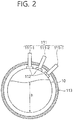
ultrasonic generation unit 110 generates an ultrasonic wave and transfers the ultrasonic wave to the inside of apipe 10. In this case, theultrasonic generation unit 110 may have a structure for effectively transferring the ultrasonic wave to the inside of thepipe 10. That is, theultrasonic generation unit 110 has a structure which minimizes the extinction of the ultrasonic wave in order to improve the accuracy of monitoring by the examination of the ultrasonic wave. As an example for implementing such a structure, referring toFIG. 2 showing a cross section of theultrasonic generation unit 110, theultrasonic generation unit 110 may include at least oneultrasonic transducer 111 which generates an ultrasonic wave, asolid contact medium 112 which brings theultrasonic transducer 111 and thepipe 10 into contact with each other and minimizes the extinction of the ultrasonic wave, and asupport unit 113 which supports theultrasonic transducer 111 so that theultrasonic transducer 111 is accurately fixed without being shaken. - The elements of the
ultrasonic generation unit 110 are described in more detail. Theultrasonic generation unit 110 includes a plurality of theultrasonic transducers 111, and may hierarchically measure a water level h within thepipe 10. For example, in this specification, the threeultrasonic transducers 111 have been illustrated as being provided at different locations in the outside of thepipe 10. The first to third ultrasonic transducers 111-1, 111-2, and 111-3 are used to sense a water level. To this end, theultrasonic transducers 111 are spaced apart and disposed in the outside of thepipe 10 in a vertical (or traverse section) direction and/or a horizontal (or longitudinal section) direction on the basis of thepipe 10. For example, as inFIG. 2 , theultrasonic transducers 111 may be spaced apart and disposed in the vertical direction (or the cross section of the pipe) on the basis of thepipe 10 so that theultrasonic transducers 111 do not overlap. Furthermore, as inFIG. 3 , theultrasonic transducers 111 may be spaced apart and disposed in the horizontal direction (or the longitudinal section of the pipe) on the basis of thepipe 10 so that theultrasonic transducers 111 do not overlap. This is for reducing interference between ultrasonic waves when the ultrasonic waves are transmitted from one side of thepipe 10, reflected by the opposite side (the other side) of thepipe 10 and then returned. - Each of the
ultrasonic transducer 111 is connected to theultrasonic examination unit 120, generates an ultrasonic wave of a specific waveform on one side of thepipe 10 by control of theultrasonic examination unit 120, and receives an ultrasonic wave reflected by a metal layer on the opposite side (the other side) of thepipe 10 and then returned. It is to be noted that the threeultrasonic transducers 111 have been illustrated as being configured in the present embodiment, but this is only an example and two or four or moreultrasonic transducers 111 may be configured. - The
solid contact medium 112 is provided on one side of theultrasonic transducer 111, and may be formed using a material which brings theultrasonic transducer 111 into contact with the outside of thepipe 10, but whose shape is not changed in order to minimize the extinction of an ultrasonic wave. - In relation to a material or property of the
solid contact medium 112, for example, the solid contact medium may be a polymer material. For another example, the solid contact medium may be a hydrophilic polymer compound. For yet another example, the solid contact medium may be a metallic material. For example, the solid contact medium may be a metallic material having softness and may be a metallic material having stiffness and may be a metallic material having both softness and stiffness. For yet another example, thesolid contact medium 112 may be a polyethylene-series ultrasonic-transmissive solid material. For yet another example, the outside cover of thesolid contact medium 112 may be made of a relatively hard material, and the inside cover thereof may be made of a relatively soft material. For yet another example, thesolid contact medium 112 may include one or more composite solid materials. For yet another example, thesolid contact medium 112 may include a single material. In relation to a contact method and form of thesolid contact medium 112, for example, thesolid contact medium 112 may have a form that is coated on a surface of thepipe 10. For another example, thesolid contact medium 112 may have a form that is attached to a surface of thepipe 10. - If such a solid contact medium is used, the
ultrasonic transducer 111 can continue to maintain its shape without being evaporated for a long time in the state in which it has come into contact with thepipe 10, and allows the solid medium to smoothly come into contact with a target object. Furthermore, thesolid contact medium 112 removes a gas pocket between theultrasonic transducer 111 and a surface of thepipe 10. Accordingly, the attenuation of an ultrasonic wave can be minimized when the ultrasonic wave generated by theultrasonic transducer 111 passes through thepipe 10, the scope of application of a method for examining an ultrasonic wave can be expanded, and the continuous monitoring of a water level can be realized. - The
support unit 113 supports theultrasonic transducer 111 so that it comes into contact with thepipe 10 stably, fixedly and continuously, and has an annular or ring-shaped holder and may surround some of or theentire pipe 10. That is, if the plurality ofultrasonic transducers 111 is provided at different locations on the outside of thepipe 10 in order to sense a danger range, a warning range and a normal range, a plurality of thesupport units 113 may be provided to individually support theultrasonic transducers 111, respectively. However, this is only an example, and the shape or form or number ofsupport units 113 may be implemented in various manners. If the examination of an ultrasonic wave is performed by a combination of onesupport unit 113 and oneultrasonic transducer 111, the combination is called a channel. A plurality of such combinations is called a multi-channel. -
FIG. 3 is a side view in which a multi-channel has been constructed in a pipe in accordance with an embodiment.FIG. 3 is an example in which three combinations of support units 113-1, 113-2, and 113-3 and ultrasonic transducers 111-1, 111-2, and 111-3 form a triple channel. - Referring back to
FIG. 1 , theultrasonic examination unit 120 controls the transmission of an ultrasonic signal by driving theultrasonic transducer 111 located in each channel, senses and collects the waveform of a reflected ultrasonic wave, and inputs/outputs the collected waveform. For example, theultrasonic examination unit 120 may control an ultrasonic signal so that it is periodically (e.g., at intervals of 10 minutes), and may periodically monitor a reflective wave. Furthermore, theultrasonic examination unit 120 is connected to thedata processing unit 130, and may transmits information about the waveform of a collected ultrasonic wave to thedata processing unit 130 or receive information stored or processed by thedata processing unit 130. - The
data processing unit 130 may determine a water level or a range to which the water level belongs based on a variety of types of information (reflective wave information, etc.) obtained from theultrasonic examination unit 120, and may process and store information about the water level. - An ultrasonic wave has a different propagation characteristic in the solid, liquid and air region, and it is divided into an ultrasonic waveform in the gas area and an ultrasonic waveform in the liquid area. Accordingly, the
ultrasonic examination unit 120 can deduce information about whether gas and liquid coexist on the internal surface of thepipe 10 or information about the results of an interaction between an ultrasonic wave and the gas area or the liquid area by monitoring and verifying the waveform of an ultrasonic wave reflected and returned from the metal layer on the opposite side of thepipe 10 after an ultrasonic wave that permeates thepipe 10 formed of the metal layer penetrates the thickness of thepipe 10 through a multi-channel. Such information is used to accurately evaluate a water level within thepipe 10. -
FIG. 4 is a cross-sectional view for illustrating the operating principle of the system for monitoring a water level within a pipe according to the present invention. - Referring to
FIG. 4 , when gas is accumulated within thepipe 10 of a safety-related system, a water level h may vary. In the present embodiment, the range of the water level h is defined to be three ranges: a normal range, a warning range, and a danger range. In order to hierarchically divide the water level h into the normal range, the warning range, and the danger range, the physical heights of the normal range, warning range, and danger range may be previously set. A user may select a point on the outside (or surface) of the pipe corresponding to each range set as described above and apply the set point to an on-site pipe. - Furthermore, the user places the
ultrasonic transducers 111 at proper levels so that they form the plurality of ranges. Each of theultrasonic transducers 111 may generate an ultrasonic wave and monitor the waveform of an ultrasonic wave reflected by the other side of thepipe 10 after the ultrasonic wave is transmitted from one side of thepipe 10. - The first ultrasonic transducer 111-1 is located at the highest level (reference location). The second ultrasonic transducer 111-2 is located at a level relatively lower than the highest level, that is, at the boundary of the normal range and the warning range. The third ultrasonic transducer 111-3 is located at the lowest level, that is, at the boundary of the warning range and the danger range. That is, the plurality of ranges to which water levels may belong along the cross section of the
pipe 10 may be formed based on the state in which the plurality ofultrasonic transducers 111 has been spaced apart and disposed on the outside of thepipe 10. The widths of the normal range, warning range, and danger range may be different depending on the interval between theultrasonic transducers 111 or a form in which theultrasonic transducers 111 have been disposed. - A method for determining the water level h based on an ultrasonic wave generated by the
ultrasonic transducer 111 and a reflective wave thereof is as follows. - 1) A case where the water level h belongs to the normal range includes the following two cases.
- i) If all of the
ultrasonic transducers 111 come into contact with the liquid area - ultrasonic waves generated by all of theultrasonic transducers 111 are reflected without being attenuated and returned to theultrasonic transducers 111 again. In this case, the reflected and returned waveforms may be monitored in a Gaussian form. Accordingly, when the reflective waves from all of theultrasonic transducers 111 are monitored, thesystem 100 for monitoring a water level within a pipe determines that the water level h belongs to the normal range. - ii) If the first ultrasonic transducer 111-1 comes into contact with the gas area and the second ultrasonic transducer 111-2 and the third ultrasonic transducer 111-3 come into contact with the liquid area - the reflective wave of an ultrasonic wave generated by the first ultrasonic transducer 111-1 is not monitored. In contrast, the reflective waves of ultrasonic waves generated by the second ultrasonic transducer 111-2 and the third ultrasonic transducer 111-3 are reflected without being attenuated and returned. Accordingly, the
system 100 for monitoring a water level within a pipe determines that the water level h belongs to the normal range up to at least a point at which the second ultrasonic transducer 111-2 monitors the reflective wave.
- i) If all of the
- 2) A case where the water level h belongs to the warning range corresponds to a case where the first ultrasonic transducer 111-1 and the second ultrasonic transducer 111-2 come into contact with the gas area and the third ultrasonic transducer 111-3 comes into contact with the liquid area. The reflective waves of ultrasonic waves generated by the first ultrasonic transducer 111-1 and the second ultrasonic transducer 111-2 are not monitored. In contrast, the reflective wave of an ultrasonic wave generated by the third ultrasonic transducer 111-3 is reflected without being attenuated and returned. Accordingly, the
system 100 for monitoring a water level within a pipe determines that the water level h belongs to the warning range up to at least a point at which the third ultrasonic transducer 111-3 monitors the reflective wave. - 3) A case where the water level h belongs to the danger range corresponds to a case where all of the first ultrasonic transducer 111-1, the second ultrasonic transducer 111-2, and the third ultrasonic transducer 111-3 come into contact with the gas area. Accordingly, the reflective waves of ultrasonic waves generated by the first ultrasonic transducer 111-1, the second ultrasonic transducer 111-2, and the third ultrasonic transducer 111-3 are not monitored. Accordingly, the
system 100 for monitoring a water level within a pipe determines that the water level h belongs to the danger range from a point of time at which all of theultrasonic transducers 111 do not monitor the reflective waves. -
FIG. 5 is a flowchart illustrating a method for configuring the system for monitoring a water level within a pipe according to an embodiment of the present invention. - Referring to
FIG. 5 , the method for installing thesystem 100 for monitoring a water level within a pipe on thepipe 10 includes step S500 of checking the connection state of the at least oneultrasonic transducer 111+the solid contact medium 112+theultrasonic examination unit 120, step S505 of checking the waveform of an ultrasonic wave that is generated by theultrasonic transducer 111 and that then passes through thesolid contact medium 112 and the liquid area, and step S510 of checking whether the reflective wave of an ultrasonic wave is present in the liquid area or not. For example, at the early stage of installation, a user may check whether the connection state of the elements is corrected by monitoring the waveform of an ultrasonic wave that is generated by theultrasonic transducer 111 and that is reflected through thesolid contact medium 112 and the liquid area. Furthermore, in the method for monitoring a water level according to the present embodiment, it is necessary to prevent an error of information for reliability of the system because accurately checking whether a reflective wave is present or not is an important factor in determining a water level within a pipe. - If a reflective wave in the liquid area is not checked at step S510, step S505 is performed. In contrast, if a reflective wave in the liquid area is checked, a user connects the
ultrasonic transducer 111 and the solid contact medium 112 (S515), selects points on a surface of the pipe by which the normal range, warning range, and danger range of the water level are classified, and disposes theultrasonic transducers 111 at levels that classify the respective ranges (S520). - As described above, the system for monitoring a water level within a pipe according to the present embodiment can perform the monitoring of a water level within a pipe on a long term basis in a nondestructive manner in relation to the accumulation of gas in a safety-related system, does not apply a physical change to the shape of a pipe and a power plant system, enables the installation and on-site application of the system to be very simple, and can continue to construct a database for a water level within a pipe through an accumulated system.
-
FIG. 6 is a flowchart illustrating an operating method of the system for monitoring a water level within a pipe according to an embodiment of the present invention. - Referring to
FIG. 6 , thesystem 100 for monitoring a water level within a pipe generates ultrasonic waves using theultrasonic transducers 111 of a multi-channel (S600). The ultrasonic waves generated by theultrasonic transducer 111 are transmitted to the inside of thepipe 10 through thesolid contact medium 112. - The
system 100 for monitoring a water level within a pipe checks whether the reflective waves of the ultrasonic waves of the respective ultrasonic transducers 111-1, 111-2, and 111-3 are present or not (S605). - The
system 100 for monitoring a water level within a pipe determines a water level within thepipe 10 based on information about the reflective waves of the ultrasonic waves of the ultrasonic transducers 111-1, 111-2, and 111-3 (S610). In this case, the information about the reflective waves is information about a combination of the presence and non-presence of the reflective waves. - A method for determining a water level within the
pipe 10 by combining the presence and non-presence of the reflective waves of the respective ultrasonic transducers is described below with reference toFIG. 4 .[Table 1] Water level within pipe Whether reflective wave of ultrasonic wave of first ultrasonic transducer is present or not Whether reflective wave of ultrasonic wave of second ultrasonic transducer is present or not Whether reflective wave of ultrasonic wave of third ultrasonic transducer is present or not Normal range O O O X O O Warning range X X O Danger range X X X - Referring to Table 1, if the reflective waves of the ultrasonic waves of all of the
ultrasonic transducers 111 are checked to be present or if the reflective waves of the ultrasonic waves of the remaining ultrasonic transducers other than the first ultrasonic transducer 111-1 are checked to be present, thesystem 100 for monitoring a water level within a pipe determines that a water level within the pipe belongs to the normal range. - Furthermore, if only the reflective wave of the ultrasonic wave of the third ultrasonic transducer 111-3 is checked to be present, the
system 100 for monitoring a water level within a pipe determines that a water level within the pipe belongs to the warning range. - Furthermore, if the reflective waves of the ultrasonic waves of all of the
ultrasonic transducers 111 are checked to be not present, thesystem 100 for monitoring a water level within a pipe determines that a water level within the pipe belongs to the danger range. - The method for monitoring a water level within a pipe according to the present embodiment may further include the step of storing information about the determined water level within the pipe in a database.
- As described above, efficiency of an operation is enhanced because a water level within a pipe can be continuously monitored while efficiently reducing the time taken to check a power plant through long-distance monitoring without directly measuring the pipe. Furthermore, excessive air can be prevented from being accumulated by continuously monitoring an air accumulation phenomenon related to the safety-pending issue of the accumulation of gas, and safety is enhanced because a water level within a pipe can be monitored without a direct change in the design of a power plant system.
- While some exemplary embodiments of the present invention have been described with reference to the accompanying drawings, those skilled in the art may change and modify the present invention in various ways without departing from the essential characteristic of the present invention. Accordingly, the disclosed embodiments should not be construed as limiting the technological spirit of the present invention, but should be construed as illustrating the technological spirit of the present invention. The scope of the technological spirit of the present invention is not restricted by the embodiments, and the range of protection of the present invention should be interpreted based on the following appended claims. Accordingly, the present invention should be construed as covering all modifications or variations derived from the meaning and scope of the appended claims and their equivalents.
Claims (31)
- A system for monitoring a water level within a pipe, comprising:an ultrasonic generation unit comprising at least one ultrasonic transducer which is disposed at spaced locations on an outside of the pipe and generates an ultrasonic wave, a solid contact medium which is provided on one side of the at least one ultrasonic transducer and brings the at least one ultrasonic transducer into contact with the outside of the pipe, and a support unit which supports the at least one ultrasonic transducer so that the transducer fixedly comes into contact with the outside of the pipe;an ultrasonic examination unit which controls the generation of the ultrasonic wave by driving the at least one ultrasonic transducer, detects a reflective wave of the ultrasonic wave, collects information about the reflective wave, and inputs/outputs the information; anda data processing unit which determines a water level based on the information about the reflective wave and processes or stores the information about the water level.
- The system of claim 1, wherein:a plurality of ranges are formed by at least one cross section of the pipe, based on a disposition of the at least one ultrasonic transducer in a vertical direction on the outside of the pipe, andthe data processing unit determines a range which belongs to the plurality of ranges and to which the water level belongs.
- The system of claim 2, wherein:the number of the at least one ultrasonic transducer is 3,a first to a third ultrasonic transducers are sequentially disposed from a highest level to a lower side along the outside of the pipe, andthe plurality of ranges comprises a normal range, a warning range, and a danger range.
- The system of claim 3, wherein when the ultrasonic examination unit detects all of reflective waves of ultrasonic waves of the first to third ultrasonic transducers or detects only reflective waves of ultrasonic waves of the second and the third ultrasonic transducers, the data processing unit determines that the water level belongs to the normal range.
- The system of claim 3, wherein when the ultrasonic examination unit detects only a reflective wave of an ultrasonic wave of the third ultrasonic transducer, the data processing unit determines that the water level belongs to the warning range.
- The system of claim 3, wherein when the ultrasonic examination unit does not detect any of reflective waves of ultrasonic waves of the first to third ultrasonic transducers, the data processing unit determines that the water level belongs to the danger range.
- The system of claim 1, wherein the at least one ultrasonic transducer is spaced apart in a horizontal direction on the outside of the pipe.
- The system of claim 1, wherein the support unit has an annular or a ring-shaped holder and completely or partly surrounds the pipe.
- The system of claim 1, wherein the solid contact medium is a polyethylene-series ultrasonic-transmissive solid material and coated on a surface of the pipe.
- The system of claim 1, wherein:an outside cover of the solid contact medium is made of a relatively hard material, andan inside cover of the solid contact medium is made of a relatively soft material.
- The system of claim 1, wherein the solid contact medium has a form attached to a surface of the pipe.
- A system for monitoring a water level within a pipe, comprising:an ultrasonic generation unit which transmits ultrasonic waves to an inside of the pipe through multiple separated channels, wherein each of the channels comprises an ultrasonic transducer generating an ultrasonic wave, a solid contact medium provided on one side of the ultrasonic transducer, and a support unit having a ring shape that surrounds an outside of the pipe and fixedly supporting the ultrasonic transducer;an ultrasonic examination unit which controls the transmission of the ultrasonic waves through the multiple channels, detects reflective waves of the ultrasonic waves, collects information about the reflective waves, and inputs/outputs the information; anda data processing unit which determines a water level based on the information about the reflective waves and processes or stores information about the water level.
- The system of claim 12, wherein:a plurality of ranges are formed by at least one cross section of the pipe, based on a disposition of the at least one ultrasonic transducer in a vertical direction on the outside of the pipe, andthe data processing unit determines a range which belongs to the plurality of ranges and to which the water level belongs.
- The system of claim 13, wherein:the number of the at least one ultrasonic transducer forming the multiple channels is 3,a first to third ultrasonic transducers are sequentially disposed from a highest level to a lower side along the outside of the pipe, andthe plurality of ranges comprises a normal range, a warning range, and a danger range.
- The system of claim 14, wherein when the ultrasonic examination unit detects all of reflective waves of ultrasonic waves of the first to third ultrasonic transducers or detects only reflective waves of ultrasonic waves of the second and the third ultrasonic transducers, the data processing unit determines that the water level belongs to the normal range.
- The system of claim 14, wherein when the ultrasonic examination unit detects only a reflective wave of an ultrasonic wave of the third ultrasonic transducer, the data processing unit determines that the water level belongs to the warning range.
- The system of claim 14, wherein when the ultrasonic examination unit does not detect any of reflective waves of ultrasonic waves of the first to third ultrasonic transducers, the data processing unit determines that the water level belongs to the danger range.
- The system of claim 12, wherein the at least one ultrasonic transducer is spaced apart in a horizontal direction on the outside of the pipe.
- The system of claim 12, wherein the solid contact medium is a polyethylene-series ultrasonic-transmissive solid material and coated on a surface of the pipe.
- The system of claim 12, wherein:an outside cover of the solid contact medium is made of a relatively hard material, andan inside cover of the solid contact medium is made of a relatively soft material.
- The system of claim 12, wherein the solid contact medium has a form attached to a surface of the pipe.
- A method for monitoring a water level within a pipe, comprising steps of:transmitting ultrasonic waves generated by a plurality of ultrasonic transducers spaced apart and disposed on an outside of the pipe to an inside of the pipe through a solid contact medium;checking whether a reflective wave of each of the ultrasonic waves is present or not; anddetermining a water level based on whether the reflective wave of each of the ultrasonic waves is present or not.
- The method of claim 22, wherein:a plurality of ranges are formed by at least one cross section of the pipe, based on a disposition of the at least one ultrasonic transducer in a vertical direction on the outside of the pipe, andthe determining step comprises determining a range which belongs to the plurality of ranges and to which the water level belongs.
- The method of claim 23, wherein:the number of the plurality of ultrasonic transducers is 3,a first to third ultrasonic transducers are sequentially disposed from a highest level to a lower side along the outside of the pipe, andthe plurality of ranges comprises a normal range, a warning range, and a danger range.
- The method of claim 24, wherein if it is checked that the reflective waves of the ultrasonic waves of the first to third ultrasonic transducers are present or only the reflective waves of the ultrasonic waves of the second and the third ultrasonic transducers are present in the checking step, the determining step comprises determining that the water level belongs to the normal range.
- The method of claim 24, wherein if it is checked that only the reflective wave of the ultrasonic wave of the third ultrasonic transducer is present in the checking step, the determining step comprises determining that the water level belongs to the warning range.
- The method of claim 24, wherein if it is checked that any of the reflective waves of the ultrasonic waves of the first to third ultrasonic transducers are not present in the checking step, the determining step comprises determining that the water level belongs to the danger range.
- The method of claim 22, wherein the at least one ultrasonic transducer is spaced apart in a horizontal direction on the outside of the pipe.
- The method of claim 22, wherein the solid contact medium is a polyethylene-series ultrasonic-transmissive solid material and coated on a surface of the pipe.
- The method of claim 22, wherein:an outside cover of the solid contact medium is made of a relatively hard material, andan inside cover of the solid contact medium is made of a relatively soft material.
- The method of claim 22, wherein the solid contact medium has a form attached to a surface of the pipe.
Applications Claiming Priority (2)
| Application Number | Priority Date | Filing Date | Title |
|---|---|---|---|
| KR1020140149431A KR101841806B1 (en) | 2014-10-30 | 2014-10-30 | Apparatus and method for monitoring water level in pipe |
| PCT/KR2014/010328 WO2016068360A1 (en) | 2014-10-30 | 2014-10-31 | Apparatus and method for monitoring water level within pipe |
Publications (3)
| Publication Number | Publication Date |
|---|---|
| EP3214417A1 true EP3214417A1 (en) | 2017-09-06 |
| EP3214417A4 EP3214417A4 (en) | 2018-06-27 |
| EP3214417B1 EP3214417B1 (en) | 2022-03-16 |
Family
ID=55857689
Family Applications (1)
| Application Number | Title | Priority Date | Filing Date |
|---|---|---|---|
| EP14904787.0A Active EP3214417B1 (en) | 2014-10-30 | 2014-10-31 | System for monitoring water level within pipe |
Country Status (6)
| Country | Link |
|---|---|
| US (1) | US10416022B2 (en) |
| EP (1) | EP3214417B1 (en) |
| JP (1) | JP2017532568A (en) |
| KR (1) | KR101841806B1 (en) |
| CN (1) | CN107003175B (en) |
| WO (1) | WO2016068360A1 (en) |
Families Citing this family (8)
| Publication number | Priority date | Publication date | Assignee | Title |
|---|---|---|---|---|
| JP6260070B1 (en) * | 2017-08-21 | 2018-01-17 | 三菱重工環境・化学エンジニアリング株式会社 | Heat transfer tube water level detection method and heat transfer tube inspection method |
| CN108627841B (en) * | 2018-01-24 | 2022-05-17 | 天津大学 | Circle center positioning method in ultrasonic detection of shallow buried pipeline |
| CN108198730B (en) * | 2018-02-26 | 2022-02-22 | 广东美的制冷设备有限公司 | Water level switch and air conditioning equipment |
| KR101983817B1 (en) | 2018-11-02 | 2019-05-29 | 주식회사 미래와도전 | Apparatus for monitoring water level using ultrasonic wave and method for calculating water level considering temperature thereof |
| KR102001209B1 (en) | 2018-11-02 | 2019-07-17 | 주식회사 미래와도전 | Clamp for water level monitoring apparatus using ultrasonic wave |
| KR101983816B1 (en) | 2018-11-02 | 2019-05-29 | 주식회사 미래와도전 | Apparatus and method for constantly monitoring and controling water level using ultrasonic wave at high temperature |
| KR102351037B1 (en) * | 2020-09-29 | 2022-01-12 | 한국수력원자력 주식회사 | Water level measurement system |
| CN115791972B (en) * | 2023-01-18 | 2023-06-06 | 河北铁达科技有限公司 | Method, terminal and storage medium for evaluating health state of steel structure upright post |
Family Cites Families (30)
| Publication number | Priority date | Publication date | Assignee | Title |
|---|---|---|---|---|
| JPH0581657A (en) | 1991-09-25 | 1993-04-02 | Matsushita Electric Ind Co Ltd | Magnetic disk |
| JPH0581657U (en) * | 1992-04-09 | 1993-11-05 | 三菱重工業株式会社 | Liquid phase level measuring device |
| JPH06281492A (en) * | 1993-03-25 | 1994-10-07 | Nuclear Fuel Ind Ltd | How to measure the water level in piping such as steam generators |
| US5438868A (en) * | 1993-11-01 | 1995-08-08 | Zevex, Inc. | Noninvasive ultrasonic liquid level indicator |
| US5719329B1 (en) * | 1995-12-28 | 1999-11-16 | Univ Ohio | Ultrasonic measuring system and method of operation |
| RU2183012C2 (en) * | 1996-04-16 | 2002-05-27 | Мобил Ойл Корпорэйшн | Method and device for metering multiphase stream |
| JPH11211877A (en) | 1998-01-30 | 1999-08-06 | Toshiba Corp | Reactor power measuring device and method of manufacturing the same |
| JP2957576B1 (en) * | 1998-09-16 | 1999-10-04 | チャン ミン テック カンパニー リミテッド | Water depth / velocity / water temperature measurement device |
| JP3796706B2 (en) * | 1999-01-22 | 2006-07-12 | 株式会社日立製作所 | Water pipe leakage monitor |
| JP2000329751A (en) | 1999-05-18 | 2000-11-30 | Toshiba Corp | Piping inspection method and equipment |
| DE102005014987A1 (en) * | 2004-04-01 | 2005-11-10 | SONOTEC Dr. zur Horst-Meyer & Münch oHG | Pipe fluid level determination procedure integrates digitised reflected signal over time before processing for use in self learning process |
| GB0428545D0 (en) * | 2004-12-31 | 2005-02-09 | Euroflow Uk Ltd | Flow methods and apparatus for detection in conduits |
| JP2007263697A (en) | 2006-03-28 | 2007-10-11 | Tokyo Electric Power Co Inc:The | Ultrasonic probe device |
| KR20080011782A (en) | 2006-07-31 | 2008-02-11 | 한국전력공사 | Hybrid furnace instrument assembly and measuring method |
| US7963175B2 (en) * | 2008-04-11 | 2011-06-21 | Expro Meters, Inc. | Clamp-on apparatus for measuring a fluid flow that includes a protective sensor housing |
| KR20100004572A (en) | 2008-07-04 | 2010-01-13 | 주식회사 에프피 | Glass frit and glass frit paste composition to sealing flat panel display |
| JP5606703B2 (en) * | 2009-04-27 | 2014-10-15 | 株式会社東芝 | Liquid level measuring device |
| WO2010144590A1 (en) * | 2009-06-09 | 2010-12-16 | Expro Meters, Inc. | Ultrasonic fluid flow meter housing with acoustically matched base |
| KR101218399B1 (en) * | 2009-08-06 | 2013-01-03 | 한국가스안전공사 | Pipe inspection device using plural channel ultra-sonic and the inspection method thereof |
| KR100960228B1 (en) | 2009-12-30 | 2010-06-01 | 주식회사 우진 | Advanced fixed type in-core instrumentation |
| CN201731918U (en) * | 2010-05-28 | 2011-02-02 | 常州联力自动化科技有限公司 | Ultrasonic type water level sensor |
| CN201748941U (en) * | 2010-08-16 | 2011-02-16 | 水利部牧区水利科学研究所 | Venturi automation water measuring device |
| KR20120028127A (en) * | 2010-09-14 | 2012-03-22 | 한국수력원자력 주식회사 | Ultrasonic inspection method of structure in a pipe |
| CA2816935C (en) | 2010-11-05 | 2020-05-05 | National Research Council Of Canada | Ultrasonic transducer assembly and system for monitoring structural integrity |
| JP2012132710A (en) | 2010-12-20 | 2012-07-12 | Toshiba Corp | Full water monitoring device of emergency core cooling system |
| JP6129480B2 (en) | 2012-04-02 | 2017-05-17 | 四国電力株式会社 | Ultrasonic liquid level measuring device |
| CN202869605U (en) * | 2012-04-11 | 2013-04-10 | 赵吉庆 | FM pulse echo method based ultrasonic liquid level measuring device |
| KR101484000B1 (en) | 2012-05-04 | 2015-01-19 | 한국수력원자력 주식회사 | Hybrid Incore Detector Assembly for Core Monitoring And Protection using eXtended Length |
| JP6026227B2 (en) * | 2012-10-31 | 2016-11-16 | 株式会社東芝 | Ultrasonic water level measuring device and ultrasonic water level measuring method |
| CN202928639U (en) * | 2012-11-22 | 2013-05-08 | 哈尔滨市三和佳美科技发展有限公司 | Rectangular section ultrasonic multi-reflection type water meter |
-
2014
- 2014-10-30 KR KR1020140149431A patent/KR101841806B1/en active Active
- 2014-10-31 JP JP2017522537A patent/JP2017532568A/en active Pending
- 2014-10-31 US US15/523,194 patent/US10416022B2/en active Active
- 2014-10-31 EP EP14904787.0A patent/EP3214417B1/en active Active
- 2014-10-31 WO PCT/KR2014/010328 patent/WO2016068360A1/en not_active Ceased
- 2014-10-31 CN CN201480083101.8A patent/CN107003175B/en active Active
Also Published As
| Publication number | Publication date |
|---|---|
| JP2017532568A (en) | 2017-11-02 |
| EP3214417B1 (en) | 2022-03-16 |
| CN107003175A (en) | 2017-08-01 |
| KR101841806B1 (en) | 2018-03-23 |
| KR20160066058A (en) | 2016-06-10 |
| US10416022B2 (en) | 2019-09-17 |
| EP3214417A4 (en) | 2018-06-27 |
| CN107003175B (en) | 2020-02-07 |
| WO2016068360A1 (en) | 2016-05-06 |
| US20170314984A1 (en) | 2017-11-02 |
Similar Documents
| Publication | Publication Date | Title |
|---|---|---|
| EP3214417B1 (en) | System for monitoring water level within pipe | |
| CA1303204C (en) | Acoustic emission leak source location | |
| US20080069290A1 (en) | Integrated monitoring method for nuclear device and system using the same | |
| CN112816835B (en) | Partial discharge positioning method based on electroacoustic combined detection signal propagation delay compensation | |
| US5400645A (en) | Method and apparatus for ultrasonic leak location | |
| CN101551361A (en) | Device for detecting lamination defect with ultrasonic wall thickness inspection and detecting method thereof | |
| JPH06186125A (en) | Ultrasonic leak position measuring method and device | |
| CN121049392B (en) | Method for non-invasively detecting pipeline sediment by using acoustic wave array | |
| WO2021247680A3 (en) | Innovative approach for pulsed neutron and array spinner measurements interpretation | |
| CN102680055A (en) | Water-hammer-preventing ultrasonic water level detection method | |
| CN120628446A (en) | A multi-sensor collaborative intelligent tank leakage diagnosis system, method and equipment | |
| KR20170102849A (en) | Apparatus and method for monitoring water level in pipe | |
| KR20160056862A (en) | Apparatus and method for monitoring water level in pipe | |
| CN112067700B (en) | Method for detecting quality of concrete joint surface by utilizing sound wave energy method | |
| CN117347083A (en) | Condenser quality detection method and system | |
| Zhang et al. | Acoustic-based detection and precise localization of seal failure points in nuclear power plant containment | |
| KR101404027B1 (en) | System, apparatus, method and computer readable recording medium of estimating precise source location for power plant structure by using a 3-d point location technique | |
| CN204201491U (en) | A kind of slug flow detection device based on differential pressure principle | |
| Macleod et al. | Acoustic monitoring techniques for structural integrity | |
| JPH02287133A (en) | Leak detector | |
| KR102788629B1 (en) | Device and Method for Setting Stress Corrosion Cracking Monitoring Indicating Parameters Using an Acoustic Emission Sensor | |
| RU101146U1 (en) | COMBINED HYDROACOUSTIC SYSTEM FOR DETECTION OF OIL PRODUCT PIPELINES | |
| CN115312221B (en) | A leakage positioning and monitoring method and system for a nuclear reactor shielded main pump | |
| CN206002266U (en) | Pressure vessel based on on-line checking | |
| KR102893700B1 (en) | System for determining Wall-Thinning of the pipe and Method for the same |
Legal Events
| Date | Code | Title | Description |
|---|---|---|---|
| STAA | Information on the status of an ep patent application or granted ep patent |
Free format text: STATUS: THE INTERNATIONAL PUBLICATION HAS BEEN MADE |
|
| PUAI | Public reference made under article 153(3) epc to a published international application that has entered the european phase |
Free format text: ORIGINAL CODE: 0009012 |
|
| STAA | Information on the status of an ep patent application or granted ep patent |
Free format text: STATUS: REQUEST FOR EXAMINATION WAS MADE |
|
| 17P | Request for examination filed |
Effective date: 20170428 |
|
| AK | Designated contracting states |
Kind code of ref document: A1 Designated state(s): AL AT BE BG CH CY CZ DE DK EE ES FI FR GB GR HR HU IE IS IT LI LT LU LV MC MK MT NL NO PL PT RO RS SE SI SK SM TR |
|
| AX | Request for extension of the european patent |
Extension state: BA ME |
|
| DAX | Request for extension of the european patent (deleted) | ||
| A4 | Supplementary search report drawn up and despatched |
Effective date: 20180530 |
|
| RIC1 | Information provided on ipc code assigned before grant |
Ipc: G01F 23/296 20060101AFI20180524BHEP Ipc: G08B 21/18 20060101ALI20180524BHEP Ipc: G01S 15/88 20060101ALI20180524BHEP |
|
| GRAP | Despatch of communication of intention to grant a patent |
Free format text: ORIGINAL CODE: EPIDOSNIGR1 |
|
| STAA | Information on the status of an ep patent application or granted ep patent |
Free format text: STATUS: GRANT OF PATENT IS INTENDED |
|
| INTG | Intention to grant announced |
Effective date: 20210924 |
|
| RAP3 | Party data changed (applicant data changed or rights of an application transferred) |
Owner name: KOREA HYDRO & NUCLEAR POWER CO., LTD |
|
| GRAS | Grant fee paid |
Free format text: ORIGINAL CODE: EPIDOSNIGR3 |
|
| GRAA | (expected) grant |
Free format text: ORIGINAL CODE: 0009210 |
|
| STAA | Information on the status of an ep patent application or granted ep patent |
Free format text: STATUS: THE PATENT HAS BEEN GRANTED |
|
| AK | Designated contracting states |
Kind code of ref document: B1 Designated state(s): AL AT BE BG CH CY CZ DE DK EE ES FI FR GB GR HR HU IE IS IT LI LT LU LV MC MK MT NL NO PL PT RO RS SE SI SK SM TR |
|
| REG | Reference to a national code |
Ref country code: GB Ref legal event code: FG4D |
|
| REG | Reference to a national code |
Ref country code: CH Ref legal event code: EP |
|
| REG | Reference to a national code |
Ref country code: DE Ref legal event code: R096 Ref document number: 602014082890 Country of ref document: DE |
|
| REG | Reference to a national code |
Ref country code: IE Ref legal event code: FG4D |
|
| REG | Reference to a national code |
Ref country code: AT Ref legal event code: REF Ref document number: 1476211 Country of ref document: AT Kind code of ref document: T Effective date: 20220415 |
|
| REG | Reference to a national code |
Ref country code: LT Ref legal event code: MG9D |
|
| REG | Reference to a national code |
Ref country code: NL Ref legal event code: MP Effective date: 20220316 |
|
| PG25 | Lapsed in a contracting state [announced via postgrant information from national office to epo] |
Ref country code: SE Free format text: LAPSE BECAUSE OF FAILURE TO SUBMIT A TRANSLATION OF THE DESCRIPTION OR TO PAY THE FEE WITHIN THE PRESCRIBED TIME-LIMIT Effective date: 20220316 Ref country code: RS Free format text: LAPSE BECAUSE OF FAILURE TO SUBMIT A TRANSLATION OF THE DESCRIPTION OR TO PAY THE FEE WITHIN THE PRESCRIBED TIME-LIMIT Effective date: 20220316 Ref country code: NO Free format text: LAPSE BECAUSE OF FAILURE TO SUBMIT A TRANSLATION OF THE DESCRIPTION OR TO PAY THE FEE WITHIN THE PRESCRIBED TIME-LIMIT Effective date: 20220616 Ref country code: LT Free format text: LAPSE BECAUSE OF FAILURE TO SUBMIT A TRANSLATION OF THE DESCRIPTION OR TO PAY THE FEE WITHIN THE PRESCRIBED TIME-LIMIT Effective date: 20220316 Ref country code: HR Free format text: LAPSE BECAUSE OF FAILURE TO SUBMIT A TRANSLATION OF THE DESCRIPTION OR TO PAY THE FEE WITHIN THE PRESCRIBED TIME-LIMIT Effective date: 20220316 Ref country code: BG Free format text: LAPSE BECAUSE OF FAILURE TO SUBMIT A TRANSLATION OF THE DESCRIPTION OR TO PAY THE FEE WITHIN THE PRESCRIBED TIME-LIMIT Effective date: 20220616 |
|
| REG | Reference to a national code |
Ref country code: AT Ref legal event code: MK05 Ref document number: 1476211 Country of ref document: AT Kind code of ref document: T Effective date: 20220316 |
|
| PG25 | Lapsed in a contracting state [announced via postgrant information from national office to epo] |
Ref country code: LV Free format text: LAPSE BECAUSE OF FAILURE TO SUBMIT A TRANSLATION OF THE DESCRIPTION OR TO PAY THE FEE WITHIN THE PRESCRIBED TIME-LIMIT Effective date: 20220316 Ref country code: GR Free format text: LAPSE BECAUSE OF FAILURE TO SUBMIT A TRANSLATION OF THE DESCRIPTION OR TO PAY THE FEE WITHIN THE PRESCRIBED TIME-LIMIT Effective date: 20220617 Ref country code: FI Free format text: LAPSE BECAUSE OF FAILURE TO SUBMIT A TRANSLATION OF THE DESCRIPTION OR TO PAY THE FEE WITHIN THE PRESCRIBED TIME-LIMIT Effective date: 20220316 |
|
| PG25 | Lapsed in a contracting state [announced via postgrant information from national office to epo] |
Ref country code: NL Free format text: LAPSE BECAUSE OF FAILURE TO SUBMIT A TRANSLATION OF THE DESCRIPTION OR TO PAY THE FEE WITHIN THE PRESCRIBED TIME-LIMIT Effective date: 20220316 |
|
| PG25 | Lapsed in a contracting state [announced via postgrant information from national office to epo] |
Ref country code: SM Free format text: LAPSE BECAUSE OF FAILURE TO SUBMIT A TRANSLATION OF THE DESCRIPTION OR TO PAY THE FEE WITHIN THE PRESCRIBED TIME-LIMIT Effective date: 20220316 Ref country code: SK Free format text: LAPSE BECAUSE OF FAILURE TO SUBMIT A TRANSLATION OF THE DESCRIPTION OR TO PAY THE FEE WITHIN THE PRESCRIBED TIME-LIMIT Effective date: 20220316 Ref country code: RO Free format text: LAPSE BECAUSE OF FAILURE TO SUBMIT A TRANSLATION OF THE DESCRIPTION OR TO PAY THE FEE WITHIN THE PRESCRIBED TIME-LIMIT Effective date: 20220316 Ref country code: PT Free format text: LAPSE BECAUSE OF FAILURE TO SUBMIT A TRANSLATION OF THE DESCRIPTION OR TO PAY THE FEE WITHIN THE PRESCRIBED TIME-LIMIT Effective date: 20220718 Ref country code: ES Free format text: LAPSE BECAUSE OF FAILURE TO SUBMIT A TRANSLATION OF THE DESCRIPTION OR TO PAY THE FEE WITHIN THE PRESCRIBED TIME-LIMIT Effective date: 20220316 Ref country code: EE Free format text: LAPSE BECAUSE OF FAILURE TO SUBMIT A TRANSLATION OF THE DESCRIPTION OR TO PAY THE FEE WITHIN THE PRESCRIBED TIME-LIMIT Effective date: 20220316 Ref country code: AT Free format text: LAPSE BECAUSE OF FAILURE TO SUBMIT A TRANSLATION OF THE DESCRIPTION OR TO PAY THE FEE WITHIN THE PRESCRIBED TIME-LIMIT Effective date: 20220316 |
|
| PG25 | Lapsed in a contracting state [announced via postgrant information from national office to epo] |
Ref country code: PL Free format text: LAPSE BECAUSE OF FAILURE TO SUBMIT A TRANSLATION OF THE DESCRIPTION OR TO PAY THE FEE WITHIN THE PRESCRIBED TIME-LIMIT Effective date: 20220316 Ref country code: IS Free format text: LAPSE BECAUSE OF FAILURE TO SUBMIT A TRANSLATION OF THE DESCRIPTION OR TO PAY THE FEE WITHIN THE PRESCRIBED TIME-LIMIT Effective date: 20220716 Ref country code: AL Free format text: LAPSE BECAUSE OF FAILURE TO SUBMIT A TRANSLATION OF THE DESCRIPTION OR TO PAY THE FEE WITHIN THE PRESCRIBED TIME-LIMIT Effective date: 20220316 |
|
| REG | Reference to a national code |
Ref country code: DE Ref legal event code: R097 Ref document number: 602014082890 Country of ref document: DE |
|
| PLBE | No opposition filed within time limit |
Free format text: ORIGINAL CODE: 0009261 |
|
| STAA | Information on the status of an ep patent application or granted ep patent |
Free format text: STATUS: NO OPPOSITION FILED WITHIN TIME LIMIT |
|
| PG25 | Lapsed in a contracting state [announced via postgrant information from national office to epo] |
Ref country code: DK Free format text: LAPSE BECAUSE OF FAILURE TO SUBMIT A TRANSLATION OF THE DESCRIPTION OR TO PAY THE FEE WITHIN THE PRESCRIBED TIME-LIMIT Effective date: 20220316 |
|
| 26N | No opposition filed |
Effective date: 20221219 |
|
| PG25 | Lapsed in a contracting state [announced via postgrant information from national office to epo] |
Ref country code: SI Free format text: LAPSE BECAUSE OF FAILURE TO SUBMIT A TRANSLATION OF THE DESCRIPTION OR TO PAY THE FEE WITHIN THE PRESCRIBED TIME-LIMIT Effective date: 20220316 |
|
| REG | Reference to a national code |
Ref country code: DE Ref legal event code: R119 Ref document number: 602014082890 Country of ref document: DE |
|
| PG25 | Lapsed in a contracting state [announced via postgrant information from national office to epo] |
Ref country code: MC Free format text: LAPSE BECAUSE OF FAILURE TO SUBMIT A TRANSLATION OF THE DESCRIPTION OR TO PAY THE FEE WITHIN THE PRESCRIBED TIME-LIMIT Effective date: 20220316 |
|
| REG | Reference to a national code |
Ref country code: CH Ref legal event code: PL |
|
| REG | Reference to a national code |
Ref country code: BE Ref legal event code: MM Effective date: 20221031 |
|
| PG25 | Lapsed in a contracting state [announced via postgrant information from national office to epo] |
Ref country code: LU Free format text: LAPSE BECAUSE OF NON-PAYMENT OF DUE FEES Effective date: 20221031 |
|
| PG25 | Lapsed in a contracting state [announced via postgrant information from national office to epo] |
Ref country code: LI Free format text: LAPSE BECAUSE OF NON-PAYMENT OF DUE FEES Effective date: 20221031 Ref country code: IT Free format text: LAPSE BECAUSE OF FAILURE TO SUBMIT A TRANSLATION OF THE DESCRIPTION OR TO PAY THE FEE WITHIN THE PRESCRIBED TIME-LIMIT Effective date: 20220316 Ref country code: DE Free format text: LAPSE BECAUSE OF NON-PAYMENT OF DUE FEES Effective date: 20230503 Ref country code: CH Free format text: LAPSE BECAUSE OF NON-PAYMENT OF DUE FEES Effective date: 20221031 |
|
| PG25 | Lapsed in a contracting state [announced via postgrant information from national office to epo] |
Ref country code: BE Free format text: LAPSE BECAUSE OF NON-PAYMENT OF DUE FEES Effective date: 20221031 |
|
| PG25 | Lapsed in a contracting state [announced via postgrant information from national office to epo] |
Ref country code: IE Free format text: LAPSE BECAUSE OF NON-PAYMENT OF DUE FEES Effective date: 20221031 |
|
| PG25 | Lapsed in a contracting state [announced via postgrant information from national office to epo] |
Ref country code: HU Free format text: LAPSE BECAUSE OF FAILURE TO SUBMIT A TRANSLATION OF THE DESCRIPTION OR TO PAY THE FEE WITHIN THE PRESCRIBED TIME-LIMIT; INVALID AB INITIO Effective date: 20141031 |
|
| PG25 | Lapsed in a contracting state [announced via postgrant information from national office to epo] |
Ref country code: CY Free format text: LAPSE BECAUSE OF FAILURE TO SUBMIT A TRANSLATION OF THE DESCRIPTION OR TO PAY THE FEE WITHIN THE PRESCRIBED TIME-LIMIT Effective date: 20220316 |
|
| PG25 | Lapsed in a contracting state [announced via postgrant information from national office to epo] |
Ref country code: MK Free format text: LAPSE BECAUSE OF FAILURE TO SUBMIT A TRANSLATION OF THE DESCRIPTION OR TO PAY THE FEE WITHIN THE PRESCRIBED TIME-LIMIT Effective date: 20220316 |
|
| PG25 | Lapsed in a contracting state [announced via postgrant information from national office to epo] |
Ref country code: TR Free format text: LAPSE BECAUSE OF FAILURE TO SUBMIT A TRANSLATION OF THE DESCRIPTION OR TO PAY THE FEE WITHIN THE PRESCRIBED TIME-LIMIT Effective date: 20220316 |
|
| PG25 | Lapsed in a contracting state [announced via postgrant information from national office to epo] |
Ref country code: MT Free format text: LAPSE BECAUSE OF FAILURE TO SUBMIT A TRANSLATION OF THE DESCRIPTION OR TO PAY THE FEE WITHIN THE PRESCRIBED TIME-LIMIT Effective date: 20220316 |
|
| PGFP | Annual fee paid to national office [announced via postgrant information from national office to epo] |
Ref country code: GB Payment date: 20251024 Year of fee payment: 12 |
|
| PGFP | Annual fee paid to national office [announced via postgrant information from national office to epo] |
Ref country code: FR Payment date: 20251024 Year of fee payment: 12 |
|
| PGFP | Annual fee paid to national office [announced via postgrant information from national office to epo] |
Ref country code: CZ Payment date: 20251003 Year of fee payment: 12 |