EP3214408A1 - Device and method for the determination of a route intersection - Google Patents
Device and method for the determination of a route intersection Download PDFInfo
- Publication number
- EP3214408A1 EP3214408A1 EP17156159.0A EP17156159A EP3214408A1 EP 3214408 A1 EP3214408 A1 EP 3214408A1 EP 17156159 A EP17156159 A EP 17156159A EP 3214408 A1 EP3214408 A1 EP 3214408A1
- Authority
- EP
- European Patent Office
- Prior art keywords
- route
- determination
- moving body
- distance information
- continuous body
- Prior art date
- Legal status (The legal status is an assumption and is not a legal conclusion. Google has not performed a legal analysis and makes no representation as to the accuracy of the status listed.)
- Granted
Links
Images




Classifications
-
- G—PHYSICS
- G01—MEASURING; TESTING
- G01C—MEASURING DISTANCES, LEVELS OR BEARINGS; SURVEYING; NAVIGATION; GYROSCOPIC INSTRUMENTS; PHOTOGRAMMETRY OR VIDEOGRAMMETRY
- G01C21/00—Navigation; Navigational instruments not provided for in groups G01C1/00 - G01C19/00
- G01C21/26—Navigation; Navigational instruments not provided for in groups G01C1/00 - G01C19/00 specially adapted for navigation in a road network
- G01C21/34—Route searching; Route guidance
- G01C21/36—Input/output arrangements for on-board computers
- G01C21/3602—Input other than that of destination using image analysis, e.g. detection of road signs, lanes, buildings, real preceding vehicles using a camera
-
- B—PERFORMING OPERATIONS; TRANSPORTING
- B60—VEHICLES IN GENERAL
- B60W—CONJOINT CONTROL OF VEHICLE SUB-UNITS OF DIFFERENT TYPE OR DIFFERENT FUNCTION; CONTROL SYSTEMS SPECIALLY ADAPTED FOR HYBRID VEHICLES; ROAD VEHICLE DRIVE CONTROL SYSTEMS FOR PURPOSES NOT RELATED TO THE CONTROL OF A PARTICULAR SUB-UNIT
- B60W40/00—Estimation or calculation of non-directly measurable driving parameters for road vehicle drive control systems not related to the control of a particular sub unit, e.g. by using mathematical models
- B60W40/02—Estimation or calculation of non-directly measurable driving parameters for road vehicle drive control systems not related to the control of a particular sub unit, e.g. by using mathematical models related to ambient conditions
- B60W40/06—Road conditions
-
- G—PHYSICS
- G01—MEASURING; TESTING
- G01C—MEASURING DISTANCES, LEVELS OR BEARINGS; SURVEYING; NAVIGATION; GYROSCOPIC INSTRUMENTS; PHOTOGRAMMETRY OR VIDEOGRAMMETRY
- G01C21/00—Navigation; Navigational instruments not provided for in groups G01C1/00 - G01C19/00
- G01C21/26—Navigation; Navigational instruments not provided for in groups G01C1/00 - G01C19/00 specially adapted for navigation in a road network
- G01C21/34—Route searching; Route guidance
- G01C21/36—Input/output arrangements for on-board computers
- G01C21/3697—Output of additional, non-guidance related information, e.g. low fuel level
-
- G—PHYSICS
- G01—MEASURING; TESTING
- G01S—RADIO DIRECTION-FINDING; RADIO NAVIGATION; DETERMINING DISTANCE OR VELOCITY BY USE OF RADIO WAVES; LOCATING OR PRESENCE-DETECTING BY USE OF THE REFLECTION OR RERADIATION OF RADIO WAVES; ANALOGOUS ARRANGEMENTS USING OTHER WAVES
- G01S13/00—Systems using the reflection or reradiation of radio waves, e.g. radar systems; Analogous systems using reflection or reradiation of waves whose nature or wavelength is irrelevant or unspecified
- G01S13/02—Systems using reflection of radio waves, e.g. primary radar systems; Analogous systems
- G01S13/06—Systems determining position data of a target
- G01S13/42—Simultaneous measurement of distance and other co-ordinates
-
- G—PHYSICS
- G05—CONTROLLING; REGULATING
- G05D—SYSTEMS FOR CONTROLLING OR REGULATING NON-ELECTRIC VARIABLES
- G05D1/00—Control of position, course, altitude or attitude of land, water, air or space vehicles, e.g. using automatic pilots
- G05D1/02—Control of position or course in two dimensions
- G05D1/021—Control of position or course in two dimensions specially adapted to land vehicles
- G05D1/0231—Control of position or course in two dimensions specially adapted to land vehicles using optical position detecting means
- G05D1/0238—Control of position or course in two dimensions specially adapted to land vehicles using optical position detecting means using obstacle or wall sensors
- G05D1/024—Control of position or course in two dimensions specially adapted to land vehicles using optical position detecting means using obstacle or wall sensors in combination with a laser
-
- G—PHYSICS
- G05—CONTROLLING; REGULATING
- G05D—SYSTEMS FOR CONTROLLING OR REGULATING NON-ELECTRIC VARIABLES
- G05D1/00—Control of position, course, altitude or attitude of land, water, air or space vehicles, e.g. using automatic pilots
- G05D1/02—Control of position or course in two dimensions
- G05D1/021—Control of position or course in two dimensions specially adapted to land vehicles
- G05D1/0259—Control of position or course in two dimensions specially adapted to land vehicles using magnetic or electromagnetic means
-
- G—PHYSICS
- G06—COMPUTING OR CALCULATING; COUNTING
- G06V—IMAGE OR VIDEO RECOGNITION OR UNDERSTANDING
- G06V20/00—Scenes; Scene-specific elements
- G06V20/50—Context or environment of the image
- G06V20/56—Context or environment of the image exterior to a vehicle by using sensors mounted on the vehicle
-
- G—PHYSICS
- G06—COMPUTING OR CALCULATING; COUNTING
- G06V—IMAGE OR VIDEO RECOGNITION OR UNDERSTANDING
- G06V20/00—Scenes; Scene-specific elements
- G06V20/40—Scenes; Scene-specific elements in video content
- G06V20/44—Event detection
-
- G—PHYSICS
- G08—SIGNALLING
- G08G—TRAFFIC CONTROL SYSTEMS
- G08G1/00—Traffic control systems for road vehicles
- G08G1/16—Anti-collision systems
- G08G1/165—Anti-collision systems for passive traffic, e.g. including static obstacles, trees
-
- G—PHYSICS
- G08—SIGNALLING
- G08G—TRAFFIC CONTROL SYSTEMS
- G08G1/00—Traffic control systems for road vehicles
- G08G1/16—Anti-collision systems
- G08G1/166—Anti-collision systems for active traffic, e.g. moving vehicles, pedestrians, bikes
-
- G—PHYSICS
- G08—SIGNALLING
- G08G—TRAFFIC CONTROL SYSTEMS
- G08G1/00—Traffic control systems for road vehicles
- G08G1/16—Anti-collision systems
- G08G1/167—Driving aids for lane monitoring, lane changing, e.g. blind spot detection
Definitions
- the present disclosure relates to a determination device communicable with a direction distance sensor, a determination method, and a recording medium recording a program.
- in-vehicle data including first data to be used in the case of examining a state around a moving body and first position information indicating a position of the moving body and map data including second position information indicating the position of an intersection are first acquired. Subsequently, the in-vehicle data acquired at a spot within a predetermined distance from the intersection is selected on the basis of the first position information and the second position information and whether or not the characteristics of the intersection exist in the first data of the selected in-vehicle data is determined.
- the start position of a search range is determined on the basis of this specified in-vehicle data. Further, after the search direction of the in-vehicle data is determined as a time direction which is reverse to the recording time direction of the in-vehicle data, the in-vehicle data to be determined is successively selected in accordance with the search direction and whether or not characteristics corresponding to an intersection start position appear in the in-vehicle data to be determined is determined. Consequently, the in-vehicle data of the intersection start position is specified.
- the warning device for vehicle disclosed in Japanese Patent No. 5338371 includes an acquisition unit which acquires information on a state of a vehicle and information on a state around the vehicle, a determination unit which determines whether or not a warning which promotes deceleration or stop is required to be outputted based on acquired information of the acquisition unit, a warning unit which outputs a warning based on a determination result of the determination unit, and a detection unit which detects a sign which promotes deceleration or stop and is placed in a vehicle traveling direction.
- the warning unit does not output a warning or the warning unit does not output a warning until a predetermined condition is satisfied.
- One non-limiting and exemplary embodiment facilitates providing a determination device, a determination method, and a recording medium recording a program, by which detailed information on a specific region with poor visibility can be provided.
- the techniques disclosed here feature a determination device including: an input terminal which receives one or more first direction distance information representing a direction and a distance to one or more objects existing in a first range, from a first sensor mounted on a moving body; route detection circuitry which detects, a first continuous body as a first part of the one or more first direction distance information with respect to a first object among the one or more objects, and a second continuous body as a second part of the one or more first direction distance information with respect to a second object which is located farther from the moving body than the first object, among the one or more objects, in a first direction along a first route on which the moving body moves, and a third continuous body as the second part of the one or more first direction distance information, in a second direction different from the first direction; route determination circuitry which determines presence or absence of a second route along the third continuous body in a case where a length of the third continuous body is equal to or more than a first value; and an output terminal which outputs the determination result to a moving
- a determination device, a determination method, a program, and a recording medium recording a program according to the present disclosure will be detailed below with reference to the above-mentioned drawings.
- the x axis and the y axis respectively represent the width direction and the length direction of a transport machine T and the origin P0 of the both axes represents an attachment position of a direction distance sensor 1 R with respect to the transport machine T on a current position.
- an advancing direction of the transport machine T has positive values on the y axis and the right side of the advancing direction has positive values on the x axis.
- the transport machine T is an example of a moving body and is typically a vehicle.
- a specific region C is an intersection or a bending point in a route network (typically, a road network) in which the transport machine T can travel.
- a right T-junction (T-junction having right exit and straight exit) or a left T-junction (T-junction having left exit and straight exit) is a trifurcate road in which a second route R2 connects to a first route R1, on which the transport machine T travels, from the right side or the left side.
- a lower T-junction (T-junction having left exit and right exit) is a trifurcate road in which the second routes R2 connect to the first route R1, on which the transport machine T travels, from both of the right side and the left side.
- a right L-junction (right corner) and a left L-junction (left corner) are routes which are bent by approximately 90° to the right direction and the left direction respectively with respect to the advancing direction of the transport machine T.
- Fig. 1 illustrates an example of the hardware configuration of a determination device.
- Fig. 1 exemplifies a vehicle as the transport machine T.
- the direction distance sensor 1R, a direction distance sensor 1L, and a determination device 2 are mounted.
- the direction distance sensor 1 R is a laser radar or a millimeter wave radar, for example, and is attached on the right front of the transport machine T.
- the direction distance sensor 1 R scans within a measurable range thereof (in other words, within a measurable range on the right front direction of the transport machine T) by predetermined angular steps so as to emit a ranging wave for measuring a distance between an object and the direction distance sensor 1 R to a direction which is defined for every predetermined angular step, for example.
- the direction distance sensor 1 R receives a reflection wave with respect to the emitted wave (ranging wave) and derives a spatial distance to an object existing in each direction (not only a moving body but also a wall, a tree, a sign, and so on) based on the time of flight (TOF) system, for example, so as to generate direction distance information DR, which is a combination of a spatial distance and a direction corresponding to an object, for one frame.
- TOF time of flight
- the determination device 2 is housed in a casing of an electronic control unit (ECU), for example, and includes an input unit 21, a control unit 22, a non-volatile memory 23, an SRAM 24, and an output unit 25.
- ECU electronice control unit
- the input unit 21 receives the direction distance information DR from the direction distance sensor 1 R. Further, the input unit 21 forwards the received direction distance information DR to the SRAM 24 under the control of the control unit 22.
- the output unit 25 outputs information generated by the control unit 22 which will be described later to a moving body control device 3 (for example, a display device or an automatic travel control device) which is mounted on the transport machine T.
- the control unit 22 is a microcomputer, for example, and executes a program which is preliminarily stored in the non-volatile memory 23 by using the SRAM 24 as an operating region so as to function as an occlusion detection unit 31R, an occlusion detection unit 31 L, and a specific region determination unit 32 as illustrated in Fig. 2 .
- the occlusion detection unit 31R includes a recognition unit 41R, an information processing unit 42R, a past data buffer unit 43R, a coordinate transformation unit 44R, and an occlusion determination unit 45R as functional blocks.
- the recognition unit 41 R selects direction distance information DR satisfying a predetermined condition from a plurality of direction distance information DR which are obtained in a frame unit.
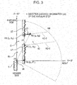
- the direction distance information DR satisfying a predetermined condition will be described below with reference to Fig. 3 .
- a region surrounded by a dashed-dotted sector is an example of a measurable range RR.
- the direction distance information DR for every angular step is denoted by a "+" mark.
- Fig. 3 illustrates direction distance information DR, which are obtained on the nearer side of (a negative direction side of the y axis) a specific region C (for example, an intersection) on the first route R1, for all angular steps.
- a narrow street (referred to below as a second route) R2 connects from the diagonally forward right, for example, on the basis of the transport machine T.
- the acquisition amount of the direction distance information DR on a first boundary R2-1 of the second route R2 (that is, a part on the negative direction side of the y axis) is small.
- the acquisition amount of the direction distance information DR on a second boundary R2-2 of the second route R2 (that is, a part on the positive direction side of the y axis) is small in a region blocked by the first continuous body U1 of the first route R1.
- a first position PA, a second position PB, and a third position PC in the xy coordinate system in the present embodiment are defined here.
- the first position PA is an intersection point between a second continuous body U2 which is a second object along the first route R1 and the second boundary R2-2 of the second route R2.
- the third position PC is an intersection point between the first continuous body U1 which is the first object along the first route R1 and the first boundary R2-1 of the second route R2.
- the break zone U4 has the width in a direction along the first route R1 in the specific region C.
- the second position PB is positioned apart from the second continuous body U2 and positioned on a third continuous body U3 along the second boundary R2-2 of the second route R2. Further, the second position PB is a right end point which can be seen from a current position P0 of the transport machine T.
- the direction distance sensor 1 R selects and outputs at least a plurality of direction distance information DR which are mostly distributed between the first position PA and the second position PB and the direction distance information DR on the third position PC among direction distance information DR for all angular steps.
- the recognition unit 41 R first selects direction distance information DR which satisfies conditional expression (1) below among direction distance information DR obtained in a frame unit as first direction distance information DR and accordingly recognizes the first continuous body U1 and the second continuous body U2 along the first route R1 on which the transport machine T travels.
- the first continuous body U1 and the second continuous body U2 are respectively the first object and the second object which partition the first route R1, such as a wall and a curb.
- I and ⁇ respectively denote a spatial distance and an azimuth in the direction distance information DR.
- I D denotes a spatial distance included in the direction distance information DR an azimuth ⁇ of which is 0°.
- ⁇ TH1 denotes a threshold value for considering that the x direction distance I ⁇ cos ⁇ of each position is substantially same as the distance I D and is a value which can be changed by setting.
- Fig. 4 illustrates an example of direction distance information DR for all angular steps on a coordinate system whose horizontal axis is denoted as ⁇ and whose vertical axis is denoted as I ⁇ cos ⁇ , to facilitate understanding.
- I A ⁇ cos ⁇ A on the first position PA and I C ⁇ cos ⁇ C on the third position PC are estimated to be within ⁇ TH1 of the distance I D of a point PD.
- the second position PB is defined by the direction distance information DR which is positioned apart from the second continuous body U2 along the first route R1 and has the smallest azimuth ⁇ among direction distance information DR which do not satisfy the conditional expression (1) above, in the present embodiment.
- the third position PC is defined by the direction distance information DR which is smaller by one angular step with respect to the second position PB.
- the first position PA is positioned apart from the third position PC by a predetermined number of (a plurality of) angular steps among first direction distance information DR which satisfy the conditional expression (1).
- the recognition unit 41 R specifies the first position PA and the third position PC described above based on first direction distance information DR which satisfy the conditional expression (1), the recognition unit 41 R recognizes that there is the break zone U4 between the first continuous body U1 and the second continuous body U2.
- the recognition unit 41 R recognizes that there is the second position PB in direction distance information DR which do not satisfy the conditional expression (1) above, the recognition unit 41 R selects direction distance information DR which are mostly distributed between the second position PB and the first position PA as the second direction distance information DR, in the present embodiment.
- the recognition unit 41 R After selecting the first direction distance information DR and the second direction distance information DR described above, the recognition unit 41 R progresses the following processing on the premise that the transport machine T is to next pass through the specific region C having poor visibility.
- the recognition unit 41 R determines whether or not there is direction distance information DR which satisfies the following conditional expression (2), based on direction distance information DR having the azimuth 0 which is larger than the azimuth ⁇ A of the first position PA.
- ⁇ TH2 denotes a threshold value for determining whether or not the specific region C is a T-junction and is a value which can be changed by setting.
- ⁇ A ⁇ 90° is satisfied.
- Fig. 5 illustrates direction distance information DR for all angular steps on a coordinate system whose horizontal axis is denoted as 0 and whose vertical axis is denoted as I ⁇ sin ⁇ , to facilitate understanding.
- the T-junction is constituted of the specific region C
- the recognition unit 41 R sets a T-junction determination flag with respect to a current frame.
- Fig. 2 is referred to again.
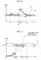
- the information processing unit 42R After transforming the direction distance information DR which are selected by the recognition unit 41 R into xy coordinate values, the information processing unit 42R linearly approximates a plurality of xy coordinate values which are distributed between the first position PA and the second position PB (refer to Fig. 6 ).
- FIG. 7 A calculation process in the information processing unit 42R will be described with reference to Fig. 7 .
- data illustrated in Fig. 7(a) is inputted from the recognition unit 41 R.
- the information processing unit 42R transforms polar coordinates from AB 1 (the point PA) to AB m (the point PB) and of the point PC into XY coordinates an origin of which is a radar position among the data illustrated in Fig. 7(a) .
- the information processing unit 42R does not process the distance I B from the radar to the point PB, the distance I C to the point PC, and the T-junction determination flag.
- the information processing unit 42R does not process the XY coordinates of the point PA, the point PB, and the point PC, the distance I B from the radar to PB, the distance I C to PC, and the T-junction determination flag.
- the information processing unit 42R outputs data illustrated in Fig. 7(c) (that is, the regression line expression, the correlation coefficient CC, the xy coordinate values from the first position PA to the third position PC, the distances I B and I C to the second position PB and the third position PC, and the T-junction determination flag) to the occlusion determination unit 45R and the past data buffer unit 43R which are on the following stages.
- data illustrated in Fig. 7(c) that is, the regression line expression, the correlation coefficient CC, the xy coordinate values from the first position PA to the third position PC, the distances I B and I C to the second position PB and the third position PC, and the T-junction determination flag
- Fig. 2 is referred to again.
- the past data buffer unit 43R an output result of the information processing unit 42R, data of current speed and steering angle, for example, of the transport machine T, and direction distance information DR for all angular steps (that is, data for one frame) are stored.
- the past data buffer unit 43R is capable of buffering data for the maximum N frames and accordingly, data for the latest n frames are accumulated when a natural number n which is equal to or smaller than N is set.
- the coordinate transformation unit 44R transforms xy coordinate values accumulated in the past data buffer unit 43R into values of a current xy coordinate system in a frame unit.
- a method for transforming direction distance information DR of n frames before from the current frame, for example, into a current coordinate system is illustrated in Fig. 8 .
- the xy coordinate system of n frames before is shifted to the x-axis direction and the y-axis direction by an amount expressed by the following expression (3) compared to the current xy coordinate system.
- ⁇ ⁇ i 1 n v 1 ⁇ cos ⁇ 1 ⁇ T f
- ⁇ ⁇ i 1 n v 1 ⁇ sin ⁇ 1 ⁇ T f
- v t denotes a speed of the transport machine T of t frames before.
- ⁇ t denotes a steering angle of t frames before.
- the steering angle represents an azimuth of the current origin P0 with respect to the origin P0 of t frames before.
- T f denotes a frame cycle.
- Fig. 2 is referred to again.
- the occlusion determination unit 45R determines presence/absence of the third continuous body U3 (that is, occlusion) along the second route R2 which connects to the specific region C and has poor visibility, based on data output illustrated in Fig. 7 (that is, current data) and data for the past n frames which are accumulated in the past data buffer unit 43R.
- the occlusion determination unit 45R includes a first position determination unit 51R, a second position determination unit 52R, a second route width determination unit 53R, a second route inclination determination unit 54R, a third position determination unit 55R, a first likelihood calculation unit 56R, and a T-junction determination unit 57R as functional blocks, as illustrated in Fig. 9 , so as to execute occlusion determination and obtain detailed information of the specific region C.
- the first position determination unit 51 R determines whether or not an xy coordinate of the first position PA (a corner on a farther side of the specific region C or a left end of the third continuous body U3) keeps indicating the same position throughout n+1 frames, based on the data output illustrated in Fig. 7 (that is, current data) and the data for the past n frames which are accumulated in the past data buffer unit 43R. Specifically, a standard deviation ( ⁇ AX , ⁇ AY ) of each of coordinates PA 0 (x A0 ,y A0 ), PA 1 (x A1 ,y A1 ), PA 2 (x A2 ,y A2 ), ..., PA n (x An ,y An ) is first calculated.
- ⁇ A denotes a threshold value for considering that a position indicated by the first position PA has not substantially changed and is a parameter which can be arbitrarily changed by setting.
- the first position determination unit 51R outputs a determination result to the first likelihood calculation unit 56R and outputs an average value of the coordinates PA 0 (x A0 ,y A0 ) to PA n (x An ,y An ) (an xy coordinate value of the first position PA) to the specific region determination unit 32.
- the second position determination unit 52R determines whether or not an xy coordinate of the third position PC keeps indicating the same position throughout n+1 frames, based on the data output illustrated in Fig. 7 (that is, current data) and the data for the past n frames which are accumulated in the past data buffer unit 43R. Specifically, the second position determination unit 52R first calculates a standard deviation ( ⁇ CX , ⁇ CY ) of each of coordinates PC 0 (x C0 ,y C0 ), PC 1 (c C1 ,y C1 ), PC 2 (x C2 ,y C2 ),..., PC n (n Cn ,y Cn ).
- the second position determination unit 52R determines that the position of the third position PC (an end portion on a front side of the specific region) has not changed.
- ⁇ C denotes a threshold value for considering that a position indicated by the third position PC has not substantially changed and is a parameter which can be arbitrarily changed by setting.
- the second position determination unit 52R outputs a determination result to the first likelihood calculation unit 56R and outputs an average value of the coordinates PC 0 (x C0 ,y C0 ) to PC n (x Cn ,y Cn ) (an xy coordinate value of the third position PC) to the specific region determination unit 32.
- the second route width determination unit 53R determines a possibility of appearance of another moving body from the second route R2 toward the specific region C. Specifically, the second route width determination unit 53R calculates the distance AC between the first position PA and the third position PC (for example, AC 0 ) based on xy coordinate values of the first position PA and the third position PC of the same frame (for example, coordinates PA 0 and PC 0 ). Subsequently, the second route width determination unit 53R calculates an average value AC AVE of the distances AC 0 to AC n for n+1 frames.
- the second route width determination unit 53R determines that another moving body is highly likely to appear from the second route R2 and outputs the average value AC AVE . Specifically, the second route width determination unit 53R outputs a determination result to the first likelihood calculation unit 56R and outputs the average value AC AVE as the width of the second route R2 to the specific region determination unit 32.
- AC MIN is selected as such a small value that there is no possibility that another moving body appears from the second route R2 and AC MAX is selected as such a large value that another moving body appearing from the second route R2 can be favorably seen.
- AC MIN and AC MAx are parameters which can be arbitrarily changed by setting.
- the second route inclination determination unit 54R determines that the third continuous body U3 based on the first position PA extends to a direction different from that of the second continuous body U2.
- ⁇ LEAN denotes a threshold value for considering that the distances E calculated in a frame unit are distances same as each other and is a parameter which can be arbitrarily changed by setting.
- the second route inclination determination unit 54R outputs a determination result to the first likelihood calculation unit 56R and outputs the inclination of the current regression line as the inclination of the third continuous body U3 (that is, the second route R2) to the specific region determination unit 32.
- the third position determination unit 55R determines whether or not elongation of the length of the third continuous body U3 based on the first position PA is equal to or more than a predetermined value when the transport machine T moves.
- a current coordinate of the second position PB is set as PB 0 (x B0 ,y B0 )
- a coordinate of the third position PC is set as PC 0 (x C0 ,y C0 )
- the length P0 0 PC 0 is denoted as I C0
- the length P0 0 PB 0 is denoted as I B0
- a coordinate of the second position PB of one frame before is set as B 1 (x B1 ,y B1 )
- a coordinate of the third position PC is set as C 1 (x C1 ,y C1 )
- I BC0 I BC0 -I C0
- I BC1 I BC1 -I C1 .
- the third position determination unit 55R determines that the length of the third continuous body U3 based on the first position PA has increased by a predetermined value or more.
- ⁇ OCL denotes a threshold value for considering that the second position PB is moved by the substantially same distance as the transport machine T and is a parameter which can be arbitrarily changed by setting.
- the third position determination unit 55R outputs a determination result to the first likelihood calculation unit 56R.
- the first likelihood calculation unit 56R calculates a first likelihood S R which represents whether or not the second route R2 connects with the first route R1 at the specific region C ahead, based on the outputs of the functional blocks 51 R to 55R.
- Table 1 illustrates an example of a method for calculating a likelihood.
- points are preliminarily set with respect to various determination items (in other words, the functional blocks 51 R to 55R). A point value can be arbitrarily changed.
- Each of the functional blocks 51 R to 55R sets 1 with respect to a positive determination result and sets 0 with respect to a negative determination result.
- the first likelihood calculation unit 56R multiplies a determination result by a point value for each of the determination items so as to output a sum of multiplied values as the first likelihood S R .
- Table 1 Example of likelihood calculation method Determination item Point Example of determination result (1/0) Likelihood Position of first position PA (first position determination) 10 1 10 Position of third position PC (second position determination) 10 1 10 Second route width determination 10 0 0 Second route inclination determination 10 1 10 Position of second position PB (third position determination) 10 0 0 Sum (first likelihood S R ) - - 30
- the T-junction determination unit 57R determines whether or not there is a possibility that the specific region C ahead is a T-junction, based on T-junction determination flags of a current frame and past n frames and outputs the determination result. In the present embodiment, when more than half of the T-junction determination flags of the n+1 frames are 1, the T-junction determination unit 57R outputs 1 as a determination result representing presence of a possibility of a T-junction. When more than half of the T-junction determination flags are not 1, the T-junction determination unit 57R outputs 0.
- the occlusion determination unit 45R determines whether or not the second route R2 with poor visibility connects with the specific region C ahead, and outputs a position of the first position PA (a corner on a farther side of the specific region C or a left end of the second route R2), a position of the third position PC (a corner on a front side of the specific region C), and the width and the inclination of the second route R2 in addition to the first likelihood S R , as respects the second route R2, to the specific region determination unit 32 (refer to Fig. 2 ).
- the transport machine T further includes the direction distance sensor 1 L as described above.
- the direction distance sensor 1 L is attached on a symmetrical position to the direction distance sensor 1 R based on a longitudinal center surface of the transport machine T, for example, and outputs direction distance information DL similar to the direction distance information DR.
- the input unit 21 receives the direction distance information DL from the direction distance sensor 1 L and forwards the direction distance information DL to the SRAM 24.
- the occlusion detection unit 31 L executes a method similar to that of the occlusion detection unit 31 R with respect to the direction distance information DL, and outputs a position of the first position PA, a position of the third position PC, and the width and the inclination of the second route in addition to the first likelihood S L , as respects the second route which connects to the specific region from the left side, to the specific region determination unit 32 (refer to Fig. 2 ).
- the detailed configuration of an occlusion determination unit 45L of the occlusion detection unit 31 L is illustrated with reference characters with suffix L in Fig. 9 .
- the specific region determination unit 32 calculates a final second likelihood S out relating to the specific region C, based on outputs of the occlusion detection units 31 R and 31 L. Further, the specific region determination unit 32 outputs a distance from the transport machine T to the specific region C, a shape of the specific region C, the width of an entering part from the first route R1 to the specific region C, the width of the second route R2, and an angle of the second route R2 with respect to the first route R1.
- the specific region determination unit 32 may output data relating to the second route R2 which connects to the specific region C from both of right and left sides.
- the specific region determination unit 32 will be detailed below with reference to Fig. 11 .
- the specific region determination unit 32 includes a first inclination determination unit 61, a second inclination determination unit 62, a second route width determination unit 63, a specific region shape determination unit 64, a specific region information output unit 65, and a second likelihood calculation unit 66, as illustrated in Fig. 11 .
- the first inclination determination unit 61 determines whether or not the second routes R2 on the left and right sides are approximately on the same straight line.
- a coordinate of the first position PA on the left side and a coordinate of the first position PA on the right side are first set as (x AL ,y AL ) and (x AR ,y AR ) respectively
- the inclination L M of a segment obtained by connecting these first positions PA is obtained by expression (8) below.
- L M y AR ⁇ y AL x AR ⁇ x AL
- the first inclination determination unit 61 determines whether the inclination of the second route R2 on the left side is closer to the inclination L M or the inclination of the second route R2 on the right side is closer to the inclination L M .
- L L the inclination of the second route R2 on the left side
- L R the inclination of the second route R2 on the right side
- Table 2 Determination result of first inclination determination unit 61
- L th1 denotes a threshold value for considering that the left and right crossroads are on the same straight line and is a parameter which can be arbitrarily changed by setting.
- the second inclination determination unit 62 determines whether or not the inclination of the second route R2 on the left side and the inclination of the second route R2 on the right side are not largely different from each other. Specifically, in the case where
- L th2 is a parameter which can be arbitrarily changed by setting.
- the second route width determination unit 63 determines whether or not the widths of the second routes R2 on the left and right sides are not largely different from each other. Specifically, in the case where
- D th denotes a threshold value for considering that the widths of the left and right crossroads are not largely different from each other and is a parameter which can be arbitrarily changed by setting.
- the specific region shape determination unit 64 selects a shape of the specific region corresponding to first likelihoods S L and S R of the second routes R2 on the left and right sides (outputs of the first likelihood calculation unit 56R and the like), left and right T-junction determination results (outputs of the T-junction determination unit 57R and the like), and a determination result of the first inclination determination unit 61, from a table preliminarily held (refer to Table 3 below) so as to determine a shape of the intersection ahead and output a determination result among determination results 1 to 7 shown below.
- Table 3 Example of determination result of specific region shape determination unit 64 Left and right T-junction determination results Determination result of first inclination determination unit 61 Determination result of specific region shape determination unit 64 S L >S th and S R >S th S L >S th and S R ⁇ S th S L ⁇ S th and S R >S th S L ⁇ S th and S R ⁇ S th 0 1 1: Crossroads intersection 2: Left T-junction 3: Right T-junction 0: No intersection 2 2: Left T-junction 3 3: Right T-junction Other than 0 1 4: Lower T-junction 5: Left L-junction 6: Right L-junction 7: Others (unclear) 2 7: Others (unclear) 3
- the specific region shape determination unit 64 determines the specific region as a crossroads intersection and outputs 1 as a determination result.
- S th denotes a threshold value for determining that the likelihoods S L and S R are large and is a parameter which can be arbitrarily changed by setting.
- the specific region shape determination unit 64 determines the specific region as a left T-junction and outputs 2 as a determination result.
- the specific region shape determination unit 64 determines the specific region as a lower T-junction (T-junction having left exit and right exit) and outputs 4 as a determination result.
- the specific region information output unit 65 outputs detailed information which can be derived from the first positions PA of the left and right second routes R2, the third position PC, the inclination, and the width (that is, a distance to the specific region, the width of an entering part to the specific region, an angle and the width of the second route R2 with respect to the first route R1, and the like) in addition to the determination result by the specific region shape determination unit 64.
- An output example of the specific region information output unit 65 is shown in Table 4.
- Table 4 Output example of specific region information output unit 65 Shape of specific region Distance to specific region Width of entering part Angle of second route Width of second route 0: No intersection No output No output No output No output No output 1: Crossroads intersection (y CL +y CR )/2
- y CL denotes a y coordinate on the third position PC of the second route R2 on the left side
- y CR denotes a y coordinate on the third position PC of the second route R2 on the right side
- x AL denotes an x coordinate on the first position PA of the second route R2 on the left side
- x AR denotes an x coordinate on the first position PA of the second route R2 on the right side.
- R LR denotes an interval between attachment positions of the direction distance sensors 1R and 1 L
- L L and L R denote inclinations of the left side crossroad and the right side crossroad
- D L and D R denote the widths of the left side crossroad and the right side crossroad.
- the second likelihood calculation unit 66 adds an additional value based on the determination results obtained in the second inclination determination unit 62, the second route width determination unit 63, and the specific region shape determination unit 64 to the first likelihoods S R and S L from the first likelihood calculation units 56R and 56L so as to calculate the second likelihood S out with respect to the specific region.
- Table 5 shows an example of a method for calculating an additional value.
- points for example, 10 points
- a value of a point can be arbitrarily changed.
- the second inclination determination unit 62 and the second route width determination unit 63 set 1 with respect to a positive determination result and set 0 with respect to a negative determination result.
- the second likelihood calculation unit 66 multiplies a value of a determination result by a point for each of the determination items so as to output a sum of multiplied values as an additional value.
- Table 5 Example of additional value calculation method Determination item Point Example of determination result (1/0) Likelihood Difference between inclinations of left and right crossroads 10 1 10 Difference between widths of left and right crossroads 10 0 0 Sum (additional value) - - 10
- the second likelihood calculation unit 66 calculates the second likelihood (output value) S out with respect to the intersection ahead, in accordance with an arithmetic expression defined for every determination result of the specific region shape determination unit 64.
- Table 6 shows an example of a method for calculating the second likelihood.
- the control unit 22 controls each unit based on the final second likelihood S out obtained by the above-mentioned method. For example, in the case where the second likelihood S out obtained as the second likelihood calculation unit 66 is larger than a predetermined threshold value, the control unit 22 may display information obtained as the specific region information output unit 65 on a display device, which is an example of the moving body control device 3, via the output unit 25. In addition, in the case where the transport machine T can be automatically operated and the second likelihood S out obtained as the second likelihood calculation unit 66 is larger than a predetermined threshold value, the control unit 22 may output information for automatically slowing down a speed of the transport machine T to an automatic traveling control device, which is another example of the moving body control device 3, via the output unit 25.
- the determination device 2 receives the direction distance information DR and DL which represent a distance between the transport machine T and an object existing around the transport machine T from the direction distance sensors 1 R and 1 L respectively via the input unit 21.
- the occlusion detection units 31 R and 31 L recognize the first continuous body U1 and the second continuous body U2 along the first route R1 on which the transport machine T travels, from the received direction distance information DR and DL, based on the above-mentioned expression (1).
- the occlusion detection units 31 R and 31 L specify the first position PA and the third position PC from first direction distance information DR which satisfies the conditional expression (1), the occlusion detection units 31 R and 31 L recognize that there is a break zone between the first continuous body U1 and the second continuous body U2.
- the occlusion detection units 31 R and 31 L determine the following two points on the premise that the transport machine T is to pass the specific region C with poor visibility from now. Whether or not the third continuous body U3 based on the first position PA extends to a different direction from that of the second continuous body U2 is determined as the first point, and whether or not the elongation of the length of the third continuous body U3 based on the first position PA is equal to or larger than a predetermined value is determined as the second point.
- the occlusion detection units 31 R and 31 L output a detection result relating to the second route R2.
- This detection result serves as a foundation for the second likelihood S out which is used in a control device (a display device displaying various types of information or a control device for automatic operation, for example) mounted on the transport machine T.
- this determination device 2 is capable of detecting the connection of the second route R2 having poor visibility to the specific region C through the above-described processing. Further, the determination device 2 is capable of outputting many detailed information about the specific region C which are favorable for an operator or automatic operation of the transport machine T. For example, an operator or the like of the transport machine T can grasp a shape of and the distance to a specific region existing before entering the specific region. «1-5. Additional statement»
- the transport machine T includes the direction distance sensors 1R and 1 L and the determination device 2.
- the determination device 2 may be implemented on a server device which is provided to be remote from this probe car in a data-communicable manner.
- the description in the item 1-5 is applicable to modification of the item 2 below.
- a determination device 8 is connected with direction distance sensors 7R and 7L in a communicable manner.
- the direction distance sensors 7R and 7L and the determination device 8 are mounted on a vehicle is described.
- the direction distance sensor 7R generates direction distance information DR for every frame cycle so as to output the direction distance information DR to the determination device 8 as is the case with the direction distance sensor 1 R described above. Further, it is preferable that after detecting and capturing a moving body (a human or another transport machine) within a measurable range, the direction distance sensor 7R assigns a tracking ID to this moving body so as to be able to track the moving body through a plurality of frames.
- the control unit 22 executes a program stored in the non-volatile memory 23 by using the SRAM 24 so as to function as a moving body detection unit 91R and a moving body detection unit 91 L as well as the occlusion detection unit 31R, the occlusion detection unit 31 L, and the specific region determination unit 32 as illustrated in Fig. 14 .
- processing of the occlusion detection units 31R and 31 L and the specific region determination unit 32 includes slight additions when compared with that of the above-described embodiment, so that the additions of the processing will be described below as appropriate.
- the moving body detection unit 91 R is divided into a coordinate transformation unit 101 R and a moving body determination unit 102R as functional blocks.
- the coordinate transformation unit 101R transforms a value of the direction distance information DR of a moving body received from the direction distance sensor 7R into a value of a current xy coordinate system in a frame unit.
- the definition of the current xy coordinate system is same as that in the above-described embodiment.
- the coordinate transformation unit 101R accumulates coordinate values of the moving body in the past data buffer unit 43R in a frame unit so as to output the coordinate values to the moving body determination unit 102R.
- the past data buffer unit 43R accumulates data for the latest n frames as is the case with the above-described embodiment. Further, in addition to the processing same as that of the above-described embodiment, the coordinate transformation unit 44R transforms xy coordinate values of the moving body which are accumulated in the past data buffer unit 43R and are xy coordinate values of past frames into values of a current xy coordinate system and outputs the values of the current xy coordinate system to the moving body determination unit 102R.
- the moving body determination unit 102R determines whether or not the moving body is moving in a direction substantially orthogonal to a traveling direction of the transport machine T, as respects the moving body, based on the current xy coordinate values and the xy coordinate values of the past n frames. In the case where the moving body determination unit 102R determines that the moving body is moving in the substantially orthogonal direction, the moving body determination unit 102R further receives a position of the first position PA, a position of the third position PC, an inclination of the second route R2, and the first likelihood S R which are outputted from the occlusion determination unit 45R and determines whether or not to be a moving body existing in the specific region C based on these outputs. Further, the moving body determination unit 102R calculates the third likelihood S MVR based on the determination result so as to output the third likelihood S MVR to the specific region determination unit 32.
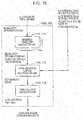
- the moving body determination unit 102R is divided into a movement trajectory calculation unit 111R, an intra-crossroad surface determination unit 112R, and a third likelihood calculation unit 113R as functional blocks as illustrated in Fig. 15 .
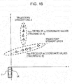
- the movement trajectory calculation unit 111 R receives xy coordinate values for n+1 frames. However, the xy coordinate value of the moving body does not always exist in all xy coordinate values. In the case where the number of xy coordinate values of the moving body is k MV pieces (k MV ⁇ n+1), the movement trajectory calculation unit 111 R applies the least squares method or the like to the k MV xy coordinate values so as to obtain an expression of a regression line (referred to below as a trajectory straight line expression) and approximate a movement trajectory of the moving body, as illustrated in Fig. 16 , by a straight line. Further, the movement trajectory calculation unit 111R calculates a correlation coefficient with respect to a regression line of the k MV xy coordinate values as well. Here, the movement trajectory calculation unit 111 R performs the above-mentioned calculation in a tracking ID unit of the moving body.
- a regression line referred to below as a trajectory straight line expression
- the movement trajectory calculation unit 111 R selects a tracking ID of an expression of a trajectory straight line an inclination of which is within I MV_th and is closest to the traveling direction of the transport machine T from the obtained trajectory straight line expressions.
- I MV_th denotes a threshold value by which an inclination can be considered to be close to the traveling direction of the transport machine T and is a parameter which can be arbitrarily changed by setting.
- the movement trajectory calculation unit 111 R outputs the tracking ID to the intra-crossroad surface determination unit 112R with a moving body determination flag set as 1 and also outputs the trajectory straight line expression to the intra-crossroad surface determination unit 112R.
- the intra-crossroad surface determination unit 112R sets a determination result as 1 in the case where all of the following expressions (9) to (12) are satisfied, while the intra-crossroad surface determination unit 112R sets a determination result as 0 in other cases.
- the intra-crossroad surface determination unit 112R outputs the determination result to the third likelihood calculation unit 113R.
- F MV 1 S R > S th L MV ⁇ L ⁇ L th 3 Y C ⁇ L MV * X A + X C / 2 + M MV ⁇ Y A
- (x A ,y A ) denotes an xy coordinate value of the first position PA
- (x C ,y C ) denotes an xy coordinate value of the third position PC
- L denotes an inclination of the second route R2
- S R denotes the first likelihood.
- S th denotes a threshold value for determining whether or not the first likelihood S R is high
- L th3 denotes a threshold value for determining whether or not the moving body is moving in the same direction as that of the second route R2
- each of S th and L th3 is a parameter which can be arbitrarily changed by setting.
- the third likelihood calculation unit 113R calculates the third likelihood S MVR representing whether or not a moving body is present on the second route R2, based on a determination result of the intra-crossroad surface determination unit 112R.
- Table 7 shows an example of a method for calculating a likelihood.
- points are preliminarily set with respect to various determination items (that is, the intra-crossroad surface determination unit 112R). A point value can be arbitrarily changed.
- the intra-crossroad surface determination unit 112R sets 1 with respect to a positive determination result and sets 0 with respect to a negative determination result.
- the first likelihood calculation unit 56R outputs the third likelihood S MVR obtained by multiplying a determination result by a point value for each of the determination items.
- Table 7 Example of method for calculating third likelihood Determination item Point
- Example of determination result (1/0) Likelihood Determination in crossroad surface 10 1 10 Sum (third likelihood) - - 10
- the moving body detection unit 91 L calculates the third likelihood S MVL on the left side by using the method same as that of the moving body detection unit 91R, and outputs the third likelihood S MVL on the left side to the specific region determination unit 32.
- the detailed configurations of the moving body detection unit 91 L are illustrated with reference characters with suffix L in Figs. 14 and 15 .
- the specific region determination unit 32 takes into account the third likelihoods S MVR and S MVL of the moving body determination units 102R and 102L in addition to the processing described in the embodiment above, in calculation of the second likelihood S out .
- Table 8 shows an example of a method for calculating the second likelihood S out .
- a moving body which can be detected by the direction distance sensors 7R and 7L are also taken into account, being able to further enhance accuracy of a likelihood of the specific region C.
- the determination device 2 receives direction distance information from the direction distance sensor 1 R as information representing a peripheral state of the transport machine T.
- the determination device 2 may acquire information of a color and luminance for every pixel from a camera as information representing a peripheral state of the transport machine T.
- the control unit 22 performs feature point detection and the like with respect to information received from the camera so as to detect feature points and thus obtain position information representing a boundary between the first route R1 and the second route R2, in the determination device 2.
- the above-mentioned program may be not only stored in the non-volatile memory 23 to be provided but also provided by a recording medium such as a digital versatile disc (DVD) or via a communication network.
- a recording medium such as a digital versatile disc (DVD) or via a communication network.
- a determination device includes: an input terminal which receives one or more first direction distance information representing a direction and a distance to one or more objects existing in a first range, from a first sensor mounted on a moving body; route detection circuitry which detects, a first continuous body as a first part of the one or more first direction distance information with respect to a first object among the one or more objects, and a second continuous body as a second part of the one or more first direction distance information with respect to a second object which is located farther from the moving body than the first object, among the one or more objects, in a first direction along a first route on which the moving body moves, and a third continuous body as the second part of the one or more first direction distance information, in a second direction different from the first direction; route determination circuitry which determines presence or absence of a second route along the third continuous body in a case where a length of the third continuous body is equal to or more than a first value; and an output terminal which outputs the determination result to a moving body control device, the
- a determination device is the determination device of the above-mentioned first disclosure in which the first part and the second part of the one or more first direction distance information are information which are inputted into the input terminal for each determined frame cycle.
- a determination device is the determination device of the above-mentioned first disclosure in which the route detection circuitry calculates a first likelihood of the first range, the first likelihood representing whether or not the first route and the second route connect with each other, based on the detection result of the second route along the third continuous body, and the route determination circuitry determines shapes of routes including the first route and the second route, by using the first likelihood of the first range.
- a determination device is the determination device of the above-mentioned third disclosure in which the route determination circuitry obtains a first position which is an intersection point between the second continuous body and the third continuous body for each determined frame cycle, determines whether or not each first position which is acquired exists on an identical position, obtains a second position which is an end point of the first continuous body for each determined frame cycle, and determines whether or not an existing position of each second position which is acquired changes in the second direction.
- a determination device is the determination device of the above-mentioned fourth disclosure in which the route determination circuitry obtains a distance between the first position and the second position for each determined frame cycle, and determines a change of the existing position of the second position by using the distance which is obtained.
- a determination device is the determination device of the above-mentioned first disclosure in which the input terminal receives one or more second direction distance information representing a direction and a distance to the one or more objects existing in a second range, the second range being different from the first range, from a second sensor mounted on the moving body, the route detection circuitry detects a fourth continuous body as a third part of the one or more second direction distance information with respect to a third object among the one or more objects, and a fifth continuous body as a fourth part of the one or more second direction distance information with respect to a fourth object which is located farther from the moving body than the third object, among the one or more objects, in the first direction, and a sixth continuous body as the fourth part of the one or more second direction distance information, in a third direction different from the first direction, and the route determination circuitry determines presence or absence of a third route along the sixth continuous body in a case where a length of the sixth continuous body is equal to or more than a second value.
- a determination device is the determination device of the above-mentioned sixth disclosure in which the route detection circuitry calculates a first likelihood of the second range, the first likelihood representing whether or not the third route connects to the first route, based on the detection result of the third route along the fourth continuous body, and the route determination circuitry determines shapes of routes including the first route and the third route, by using the first likelihood of the second range.
- a determination device is the determination device of the above-mentioned seventh disclosure in which the route determination circuitry calculates a second likelihood representing whether or not the first route, the second route, and the third route connect with each other, based on the first likelihood of the first range and the first likelihood of the second range.
- a determination device is the determination device of the above-mentioned third disclosure and includes first moving object detection circuitry which calculates a third likelihood of the first range, the third likelihood representing whether or not another moving body exists in the second route, based on the first direction distance information; wherein the route determination circuitry determines presence or absence of the third route by using the third likelihood of the first range.
- a determination device is the determination device of the above-mentioned seventh disclosure and includes second moving object detection circuitry which calculates a third likelihood of the second range, the third likelihood representing whether or not another moving body exists in the third route, based on the second direction distance information; wherein the route determination circuitry determines presence or absence of the third route by using the third likelihood of the second range.
- a determination method includes: receiving one or more first direction distance information representing a direction and a distance to one or more objects existing in a first range, from a first sensor mounted on a moving body; detecting a first continuous body as a first part of the one or more first direction distance information with respect to a first object among the one or more objects, and a second continuous body as a second part of the one or more first direction distance information with respect to a second object which is located farther from the moving body than the first object, among the one or more objects, in a first direction along a first route on which the moving body moves, and a third continuous body as the second part of the one or more first direction distance information, in a second direction different from the first direction; determining presence or absence of a second route along the third continuous body in a case where a length of the third continuous body is equal to or more than a first value; and outputting the determination result to a moving body control device, the determination result causing the moving body control device to control the movement of the moving body.
- a program which makes a computer execute processing including: receiving one or more first direction distance information representing a distance to one or more objects existing in a first range, from a first sensor mounted on a moving body; recognizing a first continuous body as a first part of the one or more first direction distance information with respect to a first object among the one or more objects, and a second continuous body as a second part of the one or more first direction distance information with respect to a second object which is located farther from the moving body than the first object, among the one or more objects, in a first direction along a first route on which the moving body moves, and a third continuous body as the second part of the one or more first direction distance information, in a second direction different from the first direction; determining presence or absence of a second route along the third continuous body in a case where a length of the third continuous body is equal to or more than a first value; and outputting the determination result to a moving body control device, the determination result causing the moving body control device to control the
- a recording medium recording a program which makes a computer execute processing including: receiving one or more first distance information representing a distance to one or more objects existing in a first range, from a first sensor mounted on a moving body; recognizing a first continuous body as one or more first distance information with respect to a first object among the one or more objects, and a second continuous body as one or more second distance information with respect to a second object which is more distant from the moving body than the first object, among the one or more objects, in a first direction along a first route on which the moving body travels, and a third continuous body as one or more second direction distance information, in a second direction different from the first direction; determining presence or absence of a second route along the third continuous body in a case where a length of the third continuous body is equal to or more than a predetermined value; and outputting a determination result to a moving body control device mounted on the moving body.
- LSI is an integrated circuit including an input terminal and an output terminal. These functional blocks may be individually formed into one chip or part or the whole of the functional blocks may be formed into one chip.
- the circuit is sometimes referred to as an IC, a system LSI, a super LSI, or an ultra LSI depending on difference of the degree of integration.
- a method of circuit integration is not limited to LSI, but an integrated circuit may be realized by using a dedicated circuit or a general-purpose processor.
- a field programmable gate array (FPGA) which is programmable and a reconfigurable processor in which connection or setting of circuit cells inside an LSI can be reconfigured may be used after manufacturing of an LSI.
- a determination device, a determination method, and a recording medium recording a program according to the present disclosure are capable of generating information relating to a specific region to which a moving body may run out ahead a transport machine from a lateral side, and are applicable to a peripheral monitoring device of the transport machine or an automatic operation system, for example.
Landscapes
- Engineering & Computer Science (AREA)
- Radar, Positioning & Navigation (AREA)
- Remote Sensing (AREA)
- Physics & Mathematics (AREA)
- General Physics & Mathematics (AREA)
- Automation & Control Theory (AREA)
- Aviation & Aerospace Engineering (AREA)
- Electromagnetism (AREA)
- Computer Vision & Pattern Recognition (AREA)
- Multimedia (AREA)
- Theoretical Computer Science (AREA)
- Mathematical Physics (AREA)
- Transportation (AREA)
- Computer Networks & Wireless Communication (AREA)
- Optics & Photonics (AREA)
- Mechanical Engineering (AREA)
- Traffic Control Systems (AREA)
- Image Analysis (AREA)
- Image Processing (AREA)
- Optical Radar Systems And Details Thereof (AREA)
- Radar Systems Or Details Thereof (AREA)
- Business, Economics & Management (AREA)
- Health & Medical Sciences (AREA)
- Artificial Intelligence (AREA)
- Evolutionary Computation (AREA)
- Game Theory and Decision Science (AREA)
- Medical Informatics (AREA)
- Control Of Position, Course, Altitude, Or Attitude Of Moving Bodies (AREA)
Abstract
Description
- The present disclosure relates to a determination device communicable with a direction distance sensor, a determination method, and a recording medium recording a program.
- Information about an intersection through which own transport machine is to pass next has been conventionally provided to an operator of the transport machine by various methods.
- For example, in the intersection detection method disclosed in Japanese Unexamined Patent Application Publication No.
2014-106147 - Further, the warning device for vehicle disclosed in Japanese Patent No.
5338371 - It is sometimes difficult to see a road connecting to an intersection or a road existing beyond a bending point, in traveling of a vehicle in a road network. Accordingly, more detailed information on such intersection or a bending point (referred to below as a specific region) is required to be provided.
- One non-limiting and exemplary embodiment facilitates providing a determination device, a determination method, and a recording medium recording a program, by which detailed information on a specific region with poor visibility can be provided.
- In one general aspect, the techniques disclosed here feature a determination device including: an input terminal which receives one or more first direction distance information representing a direction and a distance to one or more objects existing in a first range, from a first sensor mounted on a moving body; route detection circuitry which detects, a first continuous body as a first part of the one or more first direction distance information with respect to a first object among the one or more objects, and a second continuous body as a second part of the one or more first direction distance information with respect to a second object which is located farther from the moving body than the first object, among the one or more objects, in a first direction along a first route on which the moving body moves, and a third continuous body as the second part of the one or more first direction distance information, in a second direction different from the first direction; route determination circuitry which determines presence or absence of a second route along the third continuous body in a case where a length of the third continuous body is equal to or more than a first value; and an output terminal which outputs the determination result to a moving body control device, the determination result causing the moving body control device to control the movement of the moving body.
- According to the above aspect, it is possible to provide a determination device, a determination method, and a recording medium recording a program, by which detailed information on a specific region with poor visibility can be provided.
- It should be noted that general or specific embodiments may be implemented as a system, a method, an integrated circuit, a computer program, a storage medium, or any selective combination thereof.
- Additional benefits and advantages of the disclosed embodiments will become apparent from the specification and drawings. The benefits and/or advantages may be individually obtained by the various embodiments and features of the specification and drawings, which need not all be provided in order to obtain one or more of such benefits and/or advantages.
-
-
Fig. 1 illustrates an example of the hardware configuration of a determination device according to the present disclosure; -
Fig. 2 illustrates an example of functional blocks of a control unit ofFig. 1 and an example of an occlusion detection unit; -
Fig. 3 illustrates an example of a relationship among direction distance information, a first continuous body, a break zone, and a second continuous body; -
Fig. 4 illustrates an example of direction distance information of all angular steps on a coordinate system having a horizontal axis θ and a vertical axis I·cosθ; -
Fig. 5 illustrates an example of direction distance information of all angular steps on a coordinate system having a horizontal axis θ and a vertical axis I·sinθ; -
Fig. 6 illustrates an example of an approximation straight line which is a segment obtained by connecting a first position PA and a second position PB; -
Fig. 7 illustrates an example of output information from an information processing unit ofFig. 2 ; -
Fig. 8 illustrates an example of a method for transforming direction distance information of n frames before into a current coordinate system; -
Fig. 9 illustrates an example of an occlusion determination unit ofFig. 2 ; -
Fig. 10 illustrates an example of processing of a third position determination unit ofFig. 9 ; -
Fig. 11 illustrates an example of a specific region determination unit ofFig. 2 ; -
Figs. 12A to 12C illustrate an example of a determination result of a first inclination determination unit ofFig. 11 ; -
Fig. 13 illustrates an example of the hardware configuration of a determination device according to a modification; -
Fig. 14 illustrates an example of functional blocks of a control unit ofFig. 13 and examples of a moving body detection unit and an occlusion detection unit; -
Fig. 15 illustrates an example of a moving body determination unit ofFig. 14 ; and -
Fig. 16 illustrates an example of processing of a movement trajectory calculation unit ofFig. 15 . - A determination device, a determination method, a program, and a recording medium recording a program according to the present disclosure will be detailed below with reference to the above-mentioned drawings.
- In the drawings, it is assumed that the x axis and the y axis respectively represent the width direction and the length direction of a transport machine T and the origin P0 of the both axes represents an attachment position of a
direction distance sensor 1 R with respect to the transport machine T on a current position. Further, in the present embodiment, an advancing direction of the transport machine T has positive values on the y axis and the right side of the advancing direction has positive values on the x axis. - Further, the transport machine T is an example of a moving body and is typically a vehicle. Further, a specific region C is an intersection or a bending point in a route network (typically, a road network) in which the transport machine T can travel. Further, a right T-junction (T-junction having right exit and straight exit) or a left T-junction (T-junction having left exit and straight exit) is a trifurcate road in which a second route R2 connects to a first route R1, on which the transport machine T travels, from the right side or the left side. A lower T-junction (T-junction having left exit and right exit) is a trifurcate road in which the second routes R2 connect to the first route R1, on which the transport machine T travels, from both of the right side and the left side. Further, a right L-junction (right corner) and a left L-junction (left corner) are routes which are bent by approximately 90° to the right direction and the left direction respectively with respect to the advancing direction of the transport machine T.
-
Fig. 1 illustrates an example of the hardware configuration of a determination device.Fig. 1 exemplifies a vehicle as the transport machine T. On the transport machine T, thedirection distance sensor 1R, adirection distance sensor 1L, and adetermination device 2 are mounted. - The
direction distance sensor 1 R is a laser radar or a millimeter wave radar, for example, and is attached on the right front of the transport machine T. Thedirection distance sensor 1 R scans within a measurable range thereof (in other words, within a measurable range on the right front direction of the transport machine T) by predetermined angular steps so as to emit a ranging wave for measuring a distance between an object and thedirection distance sensor 1 R to a direction which is defined for every predetermined angular step, for example. Thedirection distance sensor 1 R receives a reflection wave with respect to the emitted wave (ranging wave) and derives a spatial distance to an object existing in each direction (not only a moving body but also a wall, a tree, a sign, and so on) based on the time of flight (TOF) system, for example, so as to generate direction distance information DR, which is a combination of a spatial distance and a direction corresponding to an object, for one frame. A boundary between a road surface of a route on which the transport machine T travels and other part can be defined by the direction distance information DR of unit frame and the direction distance information DR is generated for every frame cycle. - The
determination device 2 is housed in a casing of an electronic control unit (ECU), for example, and includes aninput unit 21, acontrol unit 22, anon-volatile memory 23, an SRAM 24, and anoutput unit 25. - The
input unit 21 receives the direction distance information DR from thedirection distance sensor 1 R. Further, theinput unit 21 forwards the received direction distance information DR to theSRAM 24 under the control of thecontrol unit 22. Theoutput unit 25 outputs information generated by thecontrol unit 22 which will be described later to a moving body control device 3 (for example, a display device or an automatic travel control device) which is mounted on the transport machine T. - The
control unit 22 is a microcomputer, for example, and executes a program which is preliminarily stored in thenon-volatile memory 23 by using theSRAM 24 as an operating region so as to function as anocclusion detection unit 31R, anocclusion detection unit 31 L, and a specificregion determination unit 32 as illustrated inFig. 2 . - Further, the
occlusion detection unit 31R includes arecognition unit 41R, aninformation processing unit 42R, a pastdata buffer unit 43R, a coordinatetransformation unit 44R, and anocclusion determination unit 45R as functional blocks. - The
recognition unit 41 R selects direction distance information DR satisfying a predetermined condition from a plurality of direction distance information DR which are obtained in a frame unit. The direction distance information DR satisfying a predetermined condition will be described below with reference toFig. 3 . InFig. 3 , a region surrounded by a dashed-dotted sector is an example of a measurable range RR. Further, in the drawings, the direction distance information DR for every angular step is denoted by a "+" mark. Here, in the example ofFig. 3 , it is illustratively defined that the x-axis direction is a direction of 0° (θ=0°) and the y-axis direction is a direction of 90° (θ=90°). -
Fig. 3 illustrates direction distance information DR, which are obtained on the nearer side of (a negative direction side of the y axis) a specific region C (for example, an intersection) on the first route R1, for all angular steps. To this specific region C, a narrow street (referred to below as a second route) R2 connects from the diagonally forward right, for example, on the basis of the transport machine T. - For example, in the case where the visibility of the second route R2 from the
direction distance sensor 1 R is not satisfactory due to a first continuous body U1 which is a first object along the first route R1, the acquisition amount of the direction distance information DR on a first boundary R2-1 of the second route R2 (that is, a part on the negative direction side of the y axis) is small. Further, the acquisition amount of the direction distance information DR on a second boundary R2-2 of the second route R2 (that is, a part on the positive direction side of the y axis) is small in a region blocked by the first continuous body U1 of the first route R1. - A first position PA, a second position PB, and a third position PC in the xy coordinate system in the present embodiment are defined here. The first position PA is an intersection point between a second continuous body U2 which is a second object along the first route R1 and the second boundary R2-2 of the second route R2. The third position PC is an intersection point between the first continuous body U1 which is the first object along the first route R1 and the first boundary R2-1 of the second route R2.
- Here, between the first continuous body U1 and the second continuous body U2, there is a break zone U4 of the direction distance information DR between the first position PA and the third position PC. The break zone U4 has the width in a direction along the first route R1 in the specific region C.
- The second position PB is positioned apart from the second continuous body U2 and positioned on a third continuous body U3 along the second boundary R2-2 of the second route R2. Further, the second position PB is a right end point which can be seen from a current position P0 of the transport machine T. The
direction distance sensor 1 R selects and outputs at least a plurality of direction distance information DR which are mostly distributed between the first position PA and the second position PB and the direction distance information DR on the third position PC among direction distance information DR for all angular steps. - The
recognition unit 41 R first selects direction distance information DR which satisfies conditional expression (1) below among direction distance information DR obtained in a frame unit as first direction distance information DR and accordingly recognizes the first continuous body U1 and the second continuous body U2 along the first route R1 on which the transport machine T travels. The first continuous body U1 and the second continuous body U2 are respectively the first object and the second object which partition the first route R1, such as a wall and a curb.
- Here, I and θ respectively denote a spatial distance and an azimuth in the direction distance information DR. ID denotes a spatial distance included in the direction distance information DR an azimuth θ of which is 0°. εTH1 denotes a threshold value for considering that the x direction distance I·cosθ of each position is substantially same as the distance ID and is a value which can be changed by setting.
- Here,
Fig. 4 illustrates an example of direction distance information DR for all angular steps on a coordinate system whose horizontal axis is denoted as θ and whose vertical axis is denoted as I·cosθ, to facilitate understanding. Since the first route R1 is approximately parallel to the y axis, IA·cosθA on the first position PA and IC·cosθC on the third position PC are estimated to be within ±εTH1 of the distance ID of a point PD. The second position PB is defined by the direction distance information DR which is positioned apart from the second continuous body U2 along the first route R1 and has the smallest azimuth θ among direction distance information DR which do not satisfy the conditional expression (1) above, in the present embodiment. The third position PC is defined by the direction distance information DR which is smaller by one angular step with respect to the second position PB. The first position PA is positioned apart from the third position PC by a predetermined number of (a plurality of) angular steps among first direction distance information DR which satisfy the conditional expression (1). When therecognition unit 41 R specifies the first position PA and the third position PC described above based on first direction distance information DR which satisfy the conditional expression (1), therecognition unit 41 R recognizes that there is the break zone U4 between the first continuous body U1 and the second continuous body U2. Further, in the case where therecognition unit 41 R recognizes that there is the second position PB in direction distance information DR which do not satisfy the conditional expression (1) above, therecognition unit 41 R selects direction distance information DR which are mostly distributed between the second position PB and the first position PA as the second direction distance information DR, in the present embodiment. - After selecting the first direction distance information DR and the second direction distance information DR described above, the
recognition unit 41 R progresses the following processing on the premise that the transport machine T is to next pass through the specific region C having poor visibility. - Further, the
recognition unit 41 R determines whether or not there is direction distance information DR which satisfies the following conditional expression (2), based on direction distance information DR having the azimuth 0 which is larger than the azimuth θA of the first position PA.
- Here, εTH2 denotes a threshold value for determining whether or not the specific region C is a T-junction and is a value which can be changed by setting. Here, in the above expression (2), θA<θ<90° is satisfied.
-
Fig. 5 illustrates direction distance information DR for all angular steps on a coordinate system whose horizontal axis is denoted as 0 and whose vertical axis is denoted as I·sinθ, to facilitate understanding. In the case where the T-junction is constituted of the specific region C, there is a group of direction distance information DR which satisfy the conditional expression (2). In this case, therecognition unit 41 R sets a T-junction determination flag with respect to a current frame. -
Fig. 2 is referred to again. After transforming the direction distance information DR which are selected by therecognition unit 41 R into xy coordinate values, theinformation processing unit 42R linearly approximates a plurality of xy coordinate values which are distributed between the first position PA and the second position PB (refer toFig. 6 ). In the case where the number of xy coordinate values to be objects corresponds to m angular steps, theinformation processing unit 42R applies a least squares method, for example, with respect to the xy coordinate values corresponding to the m angular steps so as to obtain an expression of a regression line y=ax+b and obtain a correlation coefficient CC of the xy coordinate values corresponding to the m angular steps. - A calculation process in the
information processing unit 42R will be described with reference toFig. 7 . To theinformation processing unit 42R, data illustrated inFig. 7(a) is inputted from therecognition unit 41 R. - In
Fig. 7(b) , theinformation processing unit 42R transforms polar coordinates from AB1 (the point PA) to ABm (the point PB) and of the point PC into XY coordinates an origin of which is a radar position among the data illustrated inFig. 7(a) . Here, theinformation processing unit 42R does not process the distance IB from the radar to the point PB, the distance IC to the point PC, and the T-junction determination flag. - In
Fig. 7(c) , theinformation processing unit 42R calculates the expression of a regression line y=ax+b and the correlation coefficient CC by using m coordinates from AB1 (the point PA) to ABm (the point PB) among the data illustrated inFig. 7(b) . Here, theinformation processing unit 42R does not process the XY coordinates of the point PA, the point PB, and the point PC, the distance IB from the radar to PB, the distance IC to PC, and the T-junction determination flag. - The
information processing unit 42R outputs data illustrated inFig. 7(c) (that is, the regression line expression, the correlation coefficient CC, the xy coordinate values from the first position PA to the third position PC, the distances IB and IC to the second position PB and the third position PC, and the T-junction determination flag) to theocclusion determination unit 45R and the pastdata buffer unit 43R which are on the following stages. -
Fig. 2 is referred to again. In the pastdata buffer unit 43R, an output result of theinformation processing unit 42R, data of current speed and steering angle, for example, of the transport machine T, and direction distance information DR for all angular steps (that is, data for one frame) are stored. Here, the pastdata buffer unit 43R is capable of buffering data for the maximum N frames and accordingly, data for the latest n frames are accumulated when a natural number n which is equal to or smaller than N is set. - The coordinate
transformation unit 44R transforms xy coordinate values accumulated in the pastdata buffer unit 43R into values of a current xy coordinate system in a frame unit. In order to facilitate understanding, a method for transforming direction distance information DR of n frames before from the current frame, for example, into a current coordinate system is illustrated inFig. 8 . InFig. 8 , the xy coordinate system of n frames before is shifted to the x-axis direction and the y-axis direction by an amount expressed by the following expression (3) compared to the current xy coordinate system.
- Here, vt denotes a speed of the transport machine T of t frames before. φt denotes a steering angle of t frames before. In the present embodiment, the steering angle represents an azimuth of the current origin P0 with respect to the origin P0 of t frames before. Further, Tf denotes a frame cycle.
- Accordingly, when a coordinate value of n frames before is set as (xn,yn) and a current xy coordinate value is set as (xc,yc), (xn,yn) is expressed by the following expression (4).

-
Fig. 2 is referred to again. Theocclusion determination unit 45R determines presence/absence of the third continuous body U3 (that is, occlusion) along the second route R2 which connects to the specific region C and has poor visibility, based on data output illustrated inFig. 7 (that is, current data) and data for the past n frames which are accumulated in the pastdata buffer unit 43R. - The
occlusion determination unit 45R includes a firstposition determination unit 51R, a secondposition determination unit 52R, a second routewidth determination unit 53R, a second route inclination determination unit 54R, a thirdposition determination unit 55R, a firstlikelihood calculation unit 56R, and a T-junction determination unit 57R as functional blocks, as illustrated inFig. 9 , so as to execute occlusion determination and obtain detailed information of the specific region C. - The first
position determination unit 51 R determines whether or not an xy coordinate of the first position PA (a corner on a farther side of the specific region C or a left end of the third continuous body U3) keeps indicating the same position throughout n+1 frames, based on the data output illustrated inFig. 7 (that is, current data) and the data for the past n frames which are accumulated in the pastdata buffer unit 43R. Specifically, a standard deviation (σAX, σAY) of each of coordinates PA0 (xA0,yA0), PA1 (xA1,yA1), PA2 (xA2,yA2), ..., PAn (xAn,yAn) is first calculated. In the case where σAX<ΣA and σAY<ΣA are satisfied, it is determined that the position of the first position PA has not changed. Here, ΣA denotes a threshold value for considering that a position indicated by the first position PA has not substantially changed and is a parameter which can be arbitrarily changed by setting. The firstposition determination unit 51R outputs a determination result to the firstlikelihood calculation unit 56R and outputs an average value of the coordinates PA0 (xA0,yA0) to PAn (xAn,yAn) (an xy coordinate value of the first position PA) to the specificregion determination unit 32. - The second
position determination unit 52R determines whether or not an xy coordinate of the third position PC keeps indicating the same position throughout n+1 frames, based on the data output illustrated inFig. 7 (that is, current data) and the data for the past n frames which are accumulated in the pastdata buffer unit 43R. Specifically, the secondposition determination unit 52R first calculates a standard deviation (σCX, σCY) of each of coordinates PC0 (xC0,yC0), PC1 (cC1,yC1), PC2 (xC2,yC2),..., PCn (nCn,yCn). In the case where the standard deviation (σCX, σCY) satisfies σCX<ΣC and σCY<ΣC, the secondposition determination unit 52R determines that the position of the third position PC (an end portion on a front side of the specific region) has not changed. Here, ΣC denotes a threshold value for considering that a position indicated by the third position PC has not substantially changed and is a parameter which can be arbitrarily changed by setting. The secondposition determination unit 52R outputs a determination result to the firstlikelihood calculation unit 56R and outputs an average value of the coordinates PC0 (xC0,yC0) to PCn (xCn,yCn) (an xy coordinate value of the third position PC) to the specificregion determination unit 32. - The second route
width determination unit 53R determines a possibility of appearance of another moving body from the second route R2 toward the specific region C. Specifically, the second routewidth determination unit 53R calculates the distance AC between the first position PA and the third position PC (for example, AC0) based on xy coordinate values of the first position PA and the third position PC of the same frame (for example, coordinates PA0 and PC0). Subsequently, the second routewidth determination unit 53R calculates an average value ACAVE of the distances AC0 to ACn for n+1 frames. In the case where ACMIN<ACAVE<ACMAX is satisfied, the second routewidth determination unit 53R determines that another moving body is highly likely to appear from the second route R2 and outputs the average value ACAVE. Specifically, the second routewidth determination unit 53R outputs a determination result to the firstlikelihood calculation unit 56R and outputs the average value ACAVE as the width of the second route R2 to the specificregion determination unit 32. - Here, ACMIN is selected as such a small value that there is no possibility that another moving body appears from the second route R2 and ACMAX is selected as such a large value that another moving body appearing from the second route R2 can be favorably seen. Here, ACMIN and ACMAx are parameters which can be arbitrarily changed by setting.
- The second route inclination determination unit 54R determines whether or not the third continuous body U3 based on the first position PA extends toward a different direction from that of the second continuous body U2 (that is, whether or not the regression line extends as estimated) when the transport machine T moves. In particular, the second route inclination determination unit 54R examines how much the degree of proximity between the second position PB and the regression line does not change during n+1 frames. For example, the regression line of one frame before is set as y=ax+b and a coordinate of the second position PB is set as (xB,yB), the distance E between the regression line and the second position PB is expressed by expression (5) below.

- In the case where the distance E obtained by the expression (5) above satisfies E<εLEAN and the transport machine T moves, the second route inclination determination unit 54R determines that the third continuous body U3 based on the first position PA extends to a direction different from that of the second continuous body U2. Here, εLEAN denotes a threshold value for considering that the distances E calculated in a frame unit are distances same as each other and is a parameter which can be arbitrarily changed by setting. The second route inclination determination unit 54R outputs a determination result to the first
likelihood calculation unit 56R and outputs the inclination of the current regression line as the inclination of the third continuous body U3 (that is, the second route R2) to the specificregion determination unit 32. - The third
position determination unit 55R determines whether or not elongation of the length of the third continuous body U3 based on the first position PA is equal to or more than a predetermined value when the transport machine T moves. In particular, as illustrated inFig. 10 , a current coordinate of the second position PB is set as PB0 (xB0,yB0), a coordinate of the third position PC is set as PC0 (xC0,yC0), a coordinate of the current position P0 of the transport machine T is set as P00 (xP0.yP0) (xP0=yP0=0), the length P00PC0 is denoted as IC0, the length P00PB0 is denoted as IB0, a coordinate of the second position PB of one frame before is set as B1 (xB1,yB1), a coordinate of the third position PC is set as C1 (xC1,yC1), a coordinate of the position P0 of the transport machine T of one frame before is set as P01 (xP1,yP1), the length P01C1 is denoted as IC1, and the length P01B1 is denoted as IB1. Further, the angle P00PC0P01 is denoted as θP and the angle PB0PC0B1 is denoted as θB. In this case, expressions (6) and (7) below are obtained.

- Here, IBC0 is expressed as IBC0= IBC0-IC0 and IBC1 is expressed as IBC1= IBC1-IC1.
- In the case where cosθP and cosθB calculated by using the above expressions (6) and (7) for each frame satisfy |cosθP-cosθB|<εDCL and the transport machine T moves, the third
position determination unit 55R determines that the length of the third continuous body U3 based on the first position PA has increased by a predetermined value or more. Here, εOCL denotes a threshold value for considering that the second position PB is moved by the substantially same distance as the transport machine T and is a parameter which can be arbitrarily changed by setting. The thirdposition determination unit 55R outputs a determination result to the firstlikelihood calculation unit 56R. - The first
likelihood calculation unit 56R calculates a first likelihood SR which represents whether or not the second route R2 connects with the first route R1 at the specific region C ahead, based on the outputs of thefunctional blocks 51 R to 55R. Table 1 illustrates an example of a method for calculating a likelihood. In the firstlikelihood calculation unit 56R, points are preliminarily set with respect to various determination items (in other words, thefunctional blocks 51 R to 55R). A point value can be arbitrarily changed. Each of thefunctional blocks 51 R to 55R sets 1 with respect to a positive determination result and sets 0 with respect to a negative determination result. The firstlikelihood calculation unit 56R multiplies a determination result by a point value for each of the determination items so as to output a sum of multiplied values as the first likelihood SR.[Table 1] Table 1: Example of likelihood calculation method Determination item Point Example of determination result (1/0) Likelihood Position of first position PA (first position determination) 10 1 10 Position of third position PC (second position determination) 10 1 10 Second route width determination 10 0 0 Second route inclination determination 10 1 10 Position of second position PB (third position determination) 10 0 0 Sum (first likelihood SR) - - 30 - The T-
junction determination unit 57R determines whether or not there is a possibility that the specific region C ahead is a T-junction, based on T-junction determination flags of a current frame and past n frames and outputs the determination result. In the present embodiment, when more than half of the T-junction determination flags of the n+1 frames are 1, the T-junction determination unit 57Routputs 1 as a determination result representing presence of a possibility of a T-junction. When more than half of the T-junction determination flags are not 1, the T-junction determination unit 57R outputs 0. - The processing of the
occlusion detection unit 31 R has been described above in detail. In the present embodiment, theocclusion determination unit 45R determines whether or not the second route R2 with poor visibility connects with the specific region C ahead, and outputs a position of the first position PA (a corner on a farther side of the specific region C or a left end of the second route R2), a position of the third position PC (a corner on a front side of the specific region C), and the width and the inclination of the second route R2 in addition to the first likelihood SR, as respects the second route R2, to the specific region determination unit 32 (refer toFig. 2 ). - Here, the transport machine T further includes the
direction distance sensor 1 L as described above. Thedirection distance sensor 1 L is attached on a symmetrical position to thedirection distance sensor 1 R based on a longitudinal center surface of the transport machine T, for example, and outputs direction distance information DL similar to the direction distance information DR. - Further, the
input unit 21 receives the direction distance information DL from thedirection distance sensor 1 L and forwards the direction distance information DL to theSRAM 24. Theocclusion detection unit 31 L executes a method similar to that of theocclusion detection unit 31 R with respect to the direction distance information DL, and outputs a position of the first position PA, a position of the third position PC, and the width and the inclination of the second route in addition to the first likelihood SL, as respects the second route which connects to the specific region from the left side, to the specific region determination unit 32 (refer toFig. 2 ). Here, the detailed configuration of anocclusion determination unit 45L of theocclusion detection unit 31 L is illustrated with reference characters with suffix L inFig. 9 . -
Fig. 2 is referred to again. The specificregion determination unit 32 calculates a final second likelihood Sout relating to the specific region C, based on outputs of theocclusion detection units 31 R and 31 L. Further, the specificregion determination unit 32 outputs a distance from the transport machine T to the specific region C, a shape of the specific region C, the width of an entering part from the first route R1 to the specific region C, the width of the second route R2, and an angle of the second route R2 with respect to the first route R1. Here, in the case where thedirection distance sensors region determination unit 32 may output data relating to the second route R2 which connects to the specific region C from both of right and left sides. The specificregion determination unit 32 will be detailed below with reference toFig. 11 . - The specific
region determination unit 32 includes a firstinclination determination unit 61, a secondinclination determination unit 62, a second routewidth determination unit 63, a specific regionshape determination unit 64, a specific regioninformation output unit 65, and a secondlikelihood calculation unit 66, as illustrated inFig. 11 . - The first
inclination determination unit 61 determines whether or not the second routes R2 on the left and right sides are approximately on the same straight line. In particular, when a coordinate of the first position PA on the left side and a coordinate of the first position PA on the right side are first set as (xAL,yAL) and (xAR,yAR) respectively, the inclination LM of a segment obtained by connecting these first positions PA is obtained by expression (8) below.
- Further, the first
inclination determination unit 61 determines whether the inclination of the second route R2 on the left side is closer to the inclination LM or the inclination of the second route R2 on the right side is closer to the inclination LM. When the inclination of the second route R2 on the left side is denoted as LL and the inclination of the second route R2 on the right side is denoted as LR, a determination result of the firstinclination determination unit 61 is obtained as Table 2 below in the present embodiment.[Table 2] Table 2: Determination result of first inclination determination unit 61|LL-LM|<Lth1 or |LR-LM|<Lth1 Other than the left LM≥0 1: There is possibility of crossroads intersection 2: T-junction (there is second route R2 on left side) LM<0 3: T-junction (there is second route R2 on right side) - (State 1) In the case where LL and LM are approximately the same (that is, |LL-LM|<Lth1) or the case where LR and LM are approximately the same (that is, |LR-LM|<Lth1) as illustrated in
Fig. 12A , the firstinclination determination unit 61outputs 1 as a determination result as shown in Table 2 above. Further,determination result 1 represents a possibility that the specific region is a crossroads intersection. - (State 2) In the case where the state is not (state 1) and LM≥0 as illustrated in
Fig. 12B , a determination result is 2 as shown in Table 2 above. In the definition ofdetermination result 2, there is a possibility that the intersection ahead is a T-junction having a crossroad on the left side (T-junction having left exit and straight exit). - (State 3) In the case where the state is not (state 1) and LM<0 as illustrated in
Fig. 12C , a determination result is 3 as shown in Table 2 above. In the definition ofdetermination result 3, there is a possibility that the intersection ahead is a T-junction having a crossroad on the right side (T-junction having right exit and straight exit). - Here, Lth1 denotes a threshold value for considering that the left and right crossroads are on the same straight line and is a parameter which can be arbitrarily changed by setting.
- The second
inclination determination unit 62 determines whether or not the inclination of the second route R2 on the left side and the inclination of the second route R2 on the right side are not largely different from each other. Specifically, in the case where |LL-LR|<Lth2 is satisfied, the secondinclination determination unit 62 determines that the inclinations of both crossroads are not largely different from each other. Here, Lth2 is a parameter which can be arbitrarily changed by setting. - The second route
width determination unit 63 determines whether or not the widths of the second routes R2 on the left and right sides are not largely different from each other. Specifically, in the case where |DL-DR|<Dth is satisfied when the width of the second route R2 on the left side and the width of the second route R2 on the right side are respectively denoted as DL and DR, the second routewidth determination unit 63 determines that the widths of the left and right crossroads are not largely different from each other. Here, Dth denotes a threshold value for considering that the widths of the left and right crossroads are not largely different from each other and is a parameter which can be arbitrarily changed by setting. - The specific region
shape determination unit 64 selects a shape of the specific region corresponding to first likelihoods SL and SR of the second routes R2 on the left and right sides (outputs of the firstlikelihood calculation unit 56R and the like), left and right T-junction determination results (outputs of the T-junction determination unit 57R and the like), and a determination result of the firstinclination determination unit 61, from a table preliminarily held (refer to Table 3 below) so as to determine a shape of the intersection ahead and output a determination result amongdetermination results 1 to 7 shown below.[Table 3] Table 3:Example of determination result of specific region shape determination unit 64Left and right T-junction determination results Determination result of first inclination determination unit 61Determination result of specific region shape determination unit 64 SL>Sth and SR>Sth SL>Sth and SR≤Sth SL≤Sth and SR>Sth SL≤Sth and SR≤Sth 0 1 1: Crossroads intersection 2: Left T-junction 3: Right T-junction 0: No intersection 2 2: Left T- junction 3 3: Right T-junction Other than 0 1 4: Lower T-junction 5: Left L-junction 6: Right L-junction 7: Others (unclear) 2 7: Others (unclear) 3 - According to Table 3, in the case where both of the left and right T-junction determination results are 0, further, the determination result of the first
inclination determination unit 61 is 1, and the first likelihoods SL and SR exceed the threshold value Sth, the specific regionshape determination unit 64 determines the specific region as a crossroads intersection andoutputs 1 as a determination result. Here, Sth denotes a threshold value for determining that the likelihoods SL and SR are large and is a parameter which can be arbitrarily changed by setting. - Further, according to Table 3, in the case where both of the left and right T-junction determination results are 0, further, the determination result of the first
inclination determination unit 61 is 2, and the first likelihoods SL and SR exceed the threshold value Sth, the specific regionshape determination unit 64 determines the specific region as a left T-junction andoutputs 2 as a determination result. - Further, according to Table 3, in the case where neither of the left and right T-junction determination results are 0, further, the determination result of the first
inclination determination unit 61 is 1, and the first likelihoods SL and SR exceed the threshold value Sth, the specific regionshape determination unit 64 determines the specific region as a lower T-junction (T-junction having left exit and right exit) andoutputs 4 as a determination result. - Shapes of the specific region corresponding to other conditions are shown in Table 3.
- The specific region
information output unit 65 outputs detailed information which can be derived from the first positions PA of the left and right second routes R2, the third position PC, the inclination, and the width (that is, a distance to the specific region, the width of an entering part to the specific region, an angle and the width of the second route R2 with respect to the first route R1, and the like) in addition to the determination result by the specific regionshape determination unit 64. An output example of the specific regioninformation output unit 65 is shown in Table 4.[Table 4] Table 4: Output example of specific region information output unit 65Shape of specific region Distance to specific region Width of entering part Angle of second route Width of second route 0: No intersection No output No output No output No output 1: Crossroads intersection (yCL+yCR)/2 |xAR|+|xAL|+RLR tan-1((LL+LR)/2) (DL+DR)/2 2: Left T-junction yCL No output tan-1LL DL 3: Right T-junction yCR No output tan-1LR DR 4: Lower T-junction (yCL+yCR)/2 No output tan-1((LL+LR)/2) (DL+DR)/2 5: Left L-junction yCL No output tan-1LL DL 6: Right L-junction yCR No output tan-1LR DR 7: Others (unclear) No output No output No output No output - In Table 4 above, yCL denotes a y coordinate on the third position PC of the second route R2 on the left side, yCR denotes a y coordinate on the third position PC of the second route R2 on the right side, xAL denotes an x coordinate on the first position PA of the second route R2 on the left side, and xAR denotes an x coordinate on the first position PA of the second route R2 on the right side. Further, RLR denotes an interval between attachment positions of the
direction distance sensors - The second
likelihood calculation unit 66 adds an additional value based on the determination results obtained in the secondinclination determination unit 62, the second routewidth determination unit 63, and the specific regionshape determination unit 64 to the first likelihoods SR and SL from the firstlikelihood calculation units likelihood calculation unit 66, points (for example, 10 points) are set with respect to determination items (in other words, the secondinclination determination unit 62 and the second route width determination unit 63). A value of a point can be arbitrarily changed. The secondinclination determination unit 62 and the second routewidth determination unit 63 set 1 with respect to a positive determination result and set 0 with respect to a negative determination result. The secondlikelihood calculation unit 66 multiplies a value of a determination result by a point for each of the determination items so as to output a sum of multiplied values as an additional value.[Table 5] Table 5: Example of additional value calculation method Determination item Point Example of determination result (1/0) Likelihood Difference between inclinations of left and right crossroads 10 1 10 Difference between widths of left and right crossroads 10 0 0 Sum (additional value) - - 10 - Further, the second
likelihood calculation unit 66 calculates the second likelihood (output value) Sout with respect to the intersection ahead, in accordance with an arithmetic expression defined for every determination result of the specific regionshape determination unit 64. Table 6 shows an example of a method for calculating the second likelihood.[Table 6] Table 6: Example of second likelihood calculation method Shape of intersection Second likelihood Sout 0: No intersection No output 1: Crossroads intersection Sout=SL+SR+SM 2: Left T-junction Sout=SL 3: Right T-junction Sout=SR 4: Lower T-junction Sout=SL+SR+SM 5: Left L-junction Sout=SL 6: Right L-junction Sout=SR 7: Others (unclear) No output -
Fig. 1 is referred to. Thecontrol unit 22 controls each unit based on the final second likelihood Sout obtained by the above-mentioned method. For example, in the case where the second likelihood Sout obtained as the secondlikelihood calculation unit 66 is larger than a predetermined threshold value, thecontrol unit 22 may display information obtained as the specific regioninformation output unit 65 on a display device, which is an example of the movingbody control device 3, via theoutput unit 25. In addition, in the case where the transport machine T can be automatically operated and the second likelihood Sout obtained as the secondlikelihood calculation unit 66 is larger than a predetermined threshold value, thecontrol unit 22 may output information for automatically slowing down a speed of the transport machine T to an automatic traveling control device, which is another example of the movingbody control device 3, via theoutput unit 25. - As described above, according to the present embodiment, the
determination device 2 receives the direction distance information DR and DL which represent a distance between the transport machine T and an object existing around the transport machine T from thedirection distance sensors input unit 21. In thecontrol unit 22, theocclusion detection units occlusion detection units occlusion detection units - Further, in the case where the
occlusion detection units occlusion detection units - In the case where the length of the third continuous body U3 extending in the direction different from that of the second continuous body U2 from the first position PA is equal to or larger than the predetermined value as a result of this determination, the
occlusion detection units - Thus, this
determination device 2 is capable of detecting the connection of the second route R2 having poor visibility to the specific region C through the above-described processing. Further, thedetermination device 2 is capable of outputting many detailed information about the specific region C which are favorable for an operator or automatic operation of the transport machine T. For example, an operator or the like of the transport machine T can grasp a shape of and the distance to a specific region existing before entering the specific region. «1-5. Additional statement» - In the above embodiment, it is described that the transport machine T includes the
direction distance sensors determination device 2. However, in the case where the transport machine T is a probe car on which thedirection distance sensors determination device 2 may be implemented on a server device which is provided to be remote from this probe car in a data-communicable manner. Here, the description in the item 1-5 is applicable to modification of theitem 2 below. - A determination device and a determination method according to a modification of the above-described embodiment will now be described.
- As illustrated in
Fig. 13 , adetermination device 8 according to the modification is connected withdirection distance sensors direction distance sensors determination device 8 are mounted on a vehicle is described. - The
direction distance sensor 7R generates direction distance information DR for every frame cycle so as to output the direction distance information DR to thedetermination device 8 as is the case with thedirection distance sensor 1 R described above. Further, it is preferable that after detecting and capturing a moving body (a human or another transport machine) within a measurable range, thedirection distance sensor 7R assigns a tracking ID to this moving body so as to be able to track the moving body through a plurality of frames. - There is no difference in an aspect of the hardware configuration when the
determination device 8 is compared to thedetermination device 2. Therefore, components corresponding to those in the configuration ofFig. 1 are denoted with the same reference characters inFig. 13 and description of these components will be omitted. - The
control unit 22 executes a program stored in thenon-volatile memory 23 by using theSRAM 24 so as to function as a movingbody detection unit 91R and a movingbody detection unit 91 L as well as theocclusion detection unit 31R, theocclusion detection unit 31 L, and the specificregion determination unit 32 as illustrated inFig. 14 . Here, processing of theocclusion detection units region determination unit 32 includes slight additions when compared with that of the above-described embodiment, so that the additions of the processing will be described below as appropriate. - Further, the moving
body detection unit 91 R is divided into a coordinatetransformation unit 101 R and a movingbody determination unit 102R as functional blocks. - The coordinate
transformation unit 101R transforms a value of the direction distance information DR of a moving body received from thedirection distance sensor 7R into a value of a current xy coordinate system in a frame unit. The definition of the current xy coordinate system is same as that in the above-described embodiment. The coordinatetransformation unit 101R accumulates coordinate values of the moving body in the pastdata buffer unit 43R in a frame unit so as to output the coordinate values to the movingbody determination unit 102R. - Here, the past
data buffer unit 43R accumulates data for the latest n frames as is the case with the above-described embodiment. Further, in addition to the processing same as that of the above-described embodiment, the coordinatetransformation unit 44R transforms xy coordinate values of the moving body which are accumulated in the pastdata buffer unit 43R and are xy coordinate values of past frames into values of a current xy coordinate system and outputs the values of the current xy coordinate system to the movingbody determination unit 102R. - The moving
body determination unit 102R determines whether or not the moving body is moving in a direction substantially orthogonal to a traveling direction of the transport machine T, as respects the moving body, based on the current xy coordinate values and the xy coordinate values of the past n frames. In the case where the movingbody determination unit 102R determines that the moving body is moving in the substantially orthogonal direction, the movingbody determination unit 102R further receives a position of the first position PA, a position of the third position PC, an inclination of the second route R2, and the first likelihood SR which are outputted from theocclusion determination unit 45R and determines whether or not to be a moving body existing in the specific region C based on these outputs. Further, the movingbody determination unit 102R calculates the third likelihood SMVR based on the determination result so as to output the third likelihood SMVR to the specificregion determination unit 32. - In order to execute the above-mentioned processing, the moving
body determination unit 102R is divided into a movementtrajectory calculation unit 111R, an intra-crossroadsurface determination unit 112R, and a thirdlikelihood calculation unit 113R as functional blocks as illustrated inFig. 15 . - The movement
trajectory calculation unit 111 R receives xy coordinate values for n+1 frames. However, the xy coordinate value of the moving body does not always exist in all xy coordinate values. In the case where the number of xy coordinate values of the moving body is kMV pieces (kMV≤n+1), the movementtrajectory calculation unit 111 R applies the least squares method or the like to the kMV xy coordinate values so as to obtain an expression of a regression line (referred to below as a trajectory straight line expression) and approximate a movement trajectory of the moving body, as illustrated inFig. 16 , by a straight line. Further, the movementtrajectory calculation unit 111R calculates a correlation coefficient with respect to a regression line of the kMV xy coordinate values as well. Here, the movementtrajectory calculation unit 111 R performs the above-mentioned calculation in a tracking ID unit of the moving body. - The movement
trajectory calculation unit 111 R selects a tracking ID of an expression of a trajectory straight line an inclination of which is within IMV_th and is closest to the traveling direction of the transport machine T from the obtained trajectory straight line expressions. Here, IMV_th denotes a threshold value by which an inclination can be considered to be close to the traveling direction of the transport machine T and is a parameter which can be arbitrarily changed by setting. After succeeding in the selection of the tracking ID, the movementtrajectory calculation unit 111 R outputs the tracking ID to the intra-crossroadsurface determination unit 112R with a moving body determination flag set as 1 and also outputs the trajectory straight line expression to the intra-crossroadsurface determination unit 112R. - The intra-crossroad
surface determination unit 112R sets a determination result as 1 in the case where all of the following expressions (9) to (12) are satisfied, while the intra-crossroadsurface determination unit 112R sets a determination result as 0 in other cases. The intra-crossroadsurface determination unit 112R outputs the determination result to the thirdlikelihood calculation unit 113R.


- Here, (xA,yA) denotes an xy coordinate value of the first position PA, (xC,yC) denotes an xy coordinate value of the third position PC, L denotes an inclination of the second route R2, and SR denotes the first likelihood.
- Further, FMV denotes a value of the moving body determination flag and the trajectory straight line expression is expressed as y=LMVx+MMV. Here, Sth denotes a threshold value for determining whether or not the first likelihood SR is high, Lth3 denotes a threshold value for determining whether or not the moving body is moving in the same direction as that of the second route R2, and each of Sth and Lth3 is a parameter which can be arbitrarily changed by setting.
- The third
likelihood calculation unit 113R calculates the third likelihood SMVR representing whether or not a moving body is present on the second route R2, based on a determination result of the intra-crossroadsurface determination unit 112R. Table 7 shows an example of a method for calculating a likelihood. In the thirdlikelihood calculation unit 113R, points are preliminarily set with respect to various determination items (that is, the intra-crossroadsurface determination unit 112R). A point value can be arbitrarily changed. The intra-crossroadsurface determination unit 112R sets 1 with respect to a positive determination result and sets 0 with respect to a negative determination result. The firstlikelihood calculation unit 56R outputs the third likelihood SMVR obtained by multiplying a determination result by a point value for each of the determination items.[Table 7] Table 7: Example of method for calculating third likelihood Determination item Point Example of determination result (1/0) Likelihood Determination in crossroad surface 10 1 10 Sum (third likelihood) - - 10 - Here, in the same viewpoint as the above-described embodiment, the moving
body detection unit 91 L calculates the third likelihood SMVL on the left side by using the method same as that of the movingbody detection unit 91R, and outputs the third likelihood SMVL on the left side to the specificregion determination unit 32. Here, the detailed configurations of the movingbody detection unit 91 L are illustrated with reference characters with suffix L inFigs. 14 and 15 . - The specific
region determination unit 32 takes into account the third likelihoods SMVR and SMVL of the movingbody determination units [Table 8] Table 8: Example of second likelihood calculation method according to modification Shape of intersection Second likelihood Sout 0: No intersection No output 1: Crossroads intersection Sout=SL+SR+SM+SMVL+SMVR 2: Left T-junction Sout=SL+SMVL 3: Right T-junction Sout= SR+SMVR 4: Lower T-junction Sout=SL+SR+SM+SMVL+SMVR 5: Left L-junction Sout=SL+SMVL 6: Right L-junction Sout=SR+SMVR 7: Others (unclear) No output - As described above, according to the
determination device 8 of the present modification, a moving body which can be detected by thedirection distance sensors - In the above-described embodiment and modification, the
determination device 2 receives direction distance information from thedirection distance sensor 1 R as information representing a peripheral state of the transport machine T. However, not limited to this, thedetermination device 2 may acquire information of a color and luminance for every pixel from a camera as information representing a peripheral state of the transport machine T. In this case, thecontrol unit 22 performs feature point detection and the like with respect to information received from the camera so as to detect feature points and thus obtain position information representing a boundary between the first route R1 and the second route R2, in thedetermination device 2. - Further, the above-mentioned program may be not only stored in the
non-volatile memory 23 to be provided but also provided by a recording medium such as a digital versatile disc (DVD) or via a communication network. - The followings are included as various aspects of embodiments according to the present disclosure.
- A determination device according to a first disclosure includes: an input terminal which receives one or more first direction distance information representing a direction and a distance to one or more objects existing in a first range, from a first sensor mounted on a moving body; route detection circuitry which detects, a first continuous body as a first part of the one or more first direction distance information with respect to a first object among the one or more objects, and a second continuous body as a second part of the one or more first direction distance information with respect to a second object which is located farther from the moving body than the first object, among the one or more objects, in a first direction along a first route on which the moving body moves, and a third continuous body as the second part of the one or more first direction distance information, in a second direction different from the first direction; route determination circuitry which determines presence or absence of a second route along the third continuous body in a case where a length of the third continuous body is equal to or more than a first value; and an output terminal which outputs the determination result to a moving body control device, the determination result causing the moving body control device to control the movement of the moving body.
- A determination device according to a second disclosure is the determination device of the above-mentioned first disclosure in which the first part and the second part of the one or more first direction distance information are information which are inputted into the input terminal for each determined frame cycle.
- A determination device according to a third disclosure is the determination device of the above-mentioned first disclosure in which the route detection circuitry calculates a first likelihood of the first range, the first likelihood representing whether or not the first route and the second route connect with each other, based on the detection result of the second route along the third continuous body, and the route determination circuitry determines shapes of routes including the first route and the second route, by using the first likelihood of the first range.
- A determination device according to a fourth disclosure is the determination device of the above-mentioned third disclosure in which the route determination circuitry obtains a first position which is an intersection point between the second continuous body and the third continuous body for each determined frame cycle, determines whether or not each first position which is acquired exists on an identical position, obtains a second position which is an end point of the first continuous body for each determined frame cycle, and determines whether or not an existing position of each second position which is acquired changes in the second direction.
- A determination device according to a fifth disclosure is the determination device of the above-mentioned fourth disclosure in which the route determination circuitry obtains a distance between the first position and the second position for each determined frame cycle, and determines a change of the existing position of the second position by using the distance which is obtained.
- A determination device according to a sixth disclosure is the determination device of the above-mentioned first disclosure in which the input terminal receives one or more second direction distance information representing a direction and a distance to the one or more objects existing in a second range, the second range being different from the first range, from a second sensor mounted on the moving body, the route detection circuitry detects a fourth continuous body as a third part of the one or more second direction distance information with respect to a third object among the one or more objects, and a fifth continuous body as a fourth part of the one or more second direction distance information with respect to a fourth object which is located farther from the moving body than the third object, among the one or more objects, in the first direction, and a sixth continuous body as the fourth part of the one or more second direction distance information, in a third direction different from the first direction, and the route determination circuitry determines presence or absence of a third route along the sixth continuous body in a case where a length of the sixth continuous body is equal to or more than a second value.
- A determination device according to a seventh disclosure is the determination device of the above-mentioned sixth disclosure in which the route detection circuitry calculates a first likelihood of the second range, the first likelihood representing whether or not the third route connects to the first route, based on the detection result of the third route along the fourth continuous body, and the route determination circuitry determines shapes of routes including the first route and the third route, by using the first likelihood of the second range.
- A determination device according to an eighth disclosure is the determination device of the above-mentioned seventh disclosure in which the route determination circuitry calculates a second likelihood representing whether or not the first route, the second route, and the third route connect with each other, based on the first likelihood of the first range and the first likelihood of the second range.
- A determination device according to a ninth disclosure is the determination device of the above-mentioned third disclosure and includes first moving object detection circuitry which calculates a third likelihood of the first range, the third likelihood representing whether or not another moving body exists in the second route, based on the first direction distance information; wherein the route determination circuitry determines presence or absence of the third route by using the third likelihood of the first range.
- A determination device according to a tenth disclosure is the determination device of the above-mentioned seventh disclosure and includes second moving object detection circuitry which calculates a third likelihood of the second range, the third likelihood representing whether or not another moving body exists in the third route, based on the second direction distance information; wherein the route determination circuitry determines presence or absence of the third route by using the third likelihood of the second range.
- A determination method according to an eleventh disclosure includes: receiving one or more first direction distance information representing a direction and a distance to one or more objects existing in a first range, from a first sensor mounted on a moving body; detecting a first continuous body as a first part of the one or more first direction distance information with respect to a first object among the one or more objects, and a second continuous body as a second part of the one or more first direction distance information with respect to a second object which is located farther from the moving body than the first object, among the one or more objects, in a first direction along a first route on which the moving body moves, and a third continuous body as the second part of the one or more first direction distance information, in a second direction different from the first direction; determining presence or absence of a second route along the third continuous body in a case where a length of the third continuous body is equal to or more than a first value; and outputting the determination result to a moving body control device, the determination result causing the moving body control device to control the movement of the moving body.
- A program, according to a twelfth disclosure, which makes a computer execute processing including: receiving one or more first direction distance information representing a distance to one or more objects existing in a first range, from a first sensor mounted on a moving body; recognizing a first continuous body as a first part of the one or more first direction distance information with respect to a first object among the one or more objects, and a second continuous body as a second part of the one or more first direction distance information with respect to a second object which is located farther from the moving body than the first object, among the one or more objects, in a first direction along a first route on which the moving body moves, and a third continuous body as the second part of the one or more first direction distance information, in a second direction different from the first direction; determining presence or absence of a second route along the third continuous body in a case where a length of the third continuous body is equal to or more than a first value; and outputting the determination result to a moving body control device, the determination result causing the moving body control device to control the movement of the moving body.
- A recording medium, according to a thirteenth disclosure, recording a program which makes a computer execute processing including: receiving one or more first distance information representing a distance to one or more objects existing in a first range, from a first sensor mounted on a moving body; recognizing a first continuous body as one or more first distance information with respect to a first object among the one or more objects, and a second continuous body as one or more second distance information with respect to a second object which is more distant from the moving body than the first object, among the one or more objects, in a first direction along a first route on which the moving body travels, and a third continuous body as one or more second direction distance information, in a second direction different from the first direction; determining presence or absence of a second route along the third continuous body in a case where a length of the third continuous body is equal to or more than a predetermined value; and outputting a determination result to a moving body control device mounted on the moving body.
- Various embodiments are described above with reference to the accompanying drawings. However, needless to say, the present disclosure is not limited to such examples. It is obvious that a person skilled in the art can conceive various alteration examples or correction examples within the scope of the description of claims, and it shall be automatically understood that these alteration examples or correction examples also belong to the technical scope of the present disclosure. Further, various components in the above-described embodiment may be arbitrarily combined without departing from the spirit of the disclosure.
- In the above-described embodiment, such description is provided that the present disclosure is realized by the configuration with hardware. However, the present disclosure may be realized by software in cooperation with hardware.
- Further, various functional blocks used in the description of the above embodiment are typically realized as an LSI which is an integrated circuit including an input terminal and an output terminal. These functional blocks may be individually formed into one chip or part or the whole of the functional blocks may be formed into one chip. Though referring to the LSI here, the circuit is sometimes referred to as an IC, a system LSI, a super LSI, or an ultra LSI depending on difference of the degree of integration.
- Further, a method of circuit integration is not limited to LSI, but an integrated circuit may be realized by using a dedicated circuit or a general-purpose processor. A field programmable gate array (FPGA) which is programmable and a reconfigurable processor in which connection or setting of circuit cells inside an LSI can be reconfigured may be used after manufacturing of an LSI.
- Further, if a technique of circuit integration which can be replaced with the LSI appears through advancement of semiconductor technology or another derived technique, the functional blocks may be integrated obviously by using the technology. There is a possibility of application to the biotechnology and the like.
- A determination device, a determination method, and a recording medium recording a program according to the present disclosure are capable of generating information relating to a specific region to which a moving body may run out ahead a transport machine from a lateral side, and are applicable to a peripheral monitoring device of the transport machine or an automatic operation system, for example.
Claims (12)
- A determination device comprising:an input terminal which receives one or more first direction distance information representing a direction and a distance to one or more objects existing in a first range, from a first sensor mounted on a moving body;route detection circuitry which detects,a first continuous body as a first part of the one or more first direction distance information with respect to a first object among the one or more objects, and a second continuous body as a second part of the one or more first direction distance information with respect to a second object which is located farther from the moving body than the first object, among the one or more objects, in a first direction along a first route on which the moving body moves, anda third continuous body as the second part of the one or more first direction distance information, in a second direction different from the first direction;route determination circuitry which determines presence or absence of a second route along the third continuous body in a case where a length of the third continuous body is equal to or more than a first value; andan output terminal which outputs the determination result to a moving body control device, the determination result causing the moving body control device to control the movement of the moving body.
- The determination device according to Claim 1, wherein the first part and the second part of the one or more first direction distance information are information which are inputted into the input terminal for each determined frame cycle.
- The determination device according to Claim 1, wherein
the route detection circuitry calculates a first likelihood of the first range, the first likelihood representing whether or not the first route and the second route connect with each other, based on the detection result of the second route along the third continuous body, and
the route determination circuitry determines shapes of routes including the first route and the second route, by using the first likelihood of the first range. - The determination device according to Claim 3, wherein
the route determination circuitryobtains a first position which is an intersection point between the second continuous body and the third continuous body for each determined frame cycle,determines whether or not each first position which is acquired exists on an identical position,obtains a second position which is an end point of the first continuous body for each determined frame cycle, anddetermines whether or not an existing position of each second position which is acquired changes in the second direction. - The determination device according to Claim 4, wherein
the route determination circuitryobtains a distance between the first position and the second position for each determined frame cycle, anddetermines a change of the existing position of the second position by using the distance which is obtained. - The determination device according to Claim 1, wherein
the input terminal receives one or more second direction distance information representing a direction and a distance to the one or more objects existing in a second range, the second range being different from the first range, from a second sensor mounted on the moving body,
the route detection circuitry detectsa fourth continuous body as a third part of the one or more second direction distance information with respect to a third object among the one or more objects, and a fifth continuous body as a fourth part of the one or more second direction distance information with respect to a fourth object which is located farther from the moving body than the third object, among the one or more objects, in the first direction, anda sixth continuous body as the fourth part of the one or more second direction distance information, in a third direction different from the first direction, andthe route determination circuitry determines presence or absence of a third route along the sixth continuous body in a case where a length of the sixth continuous body is equal to or more than a second value. - The determination device according to Claim 6, wherein
the route detection circuitry calculates a first likelihood of the second range, the first likelihood representing whether or not the third route connects to the first route, based on the detection result of the third route along the fourth continuous body, and
the route determination circuitry determines shapes of routes including the first route and the third route, by using the first likelihood of the second range. - The determination device according to Claim 7, wherein
the route determination circuitry calculates a second likelihood representing whether or not the first route, the second route, and the third route connect with each other, based on the first likelihood of the first range and the first likelihood of the second range. - The determination device according to Claim 3, comprising:first moving object detection circuitry which calculates a third likelihood of the first range, the third likelihood representing whether or not another moving body exists in the second route, based on the first direction distance information; whereinthe route determination circuitry determines presence or absence of the third route by using the third likelihood of the first range.
- The determination device according to Claim 7, comprising:second moving object detection circuitry which calculates a third likelihood of the second range, the third likelihood representing whether or not another moving body exists in the third route, based on the second direction distance information; whereinthe route determination circuitry determines presence or absence of the third route by using the third likelihood of the second range.
- A determination method comprising:receiving one or more first direction distance information representing a direction and a distance to one or more objects existing in a first range, from a first sensor mounted on a moving body;detectinga first continuous body as a first part of the one or more first direction distance information with respect to a first object among the one or more objects, and a second continuous body as a second part of the one or more first direction distance information with respect to a second object which is located farther from the moving body than the first object, among the one or more objects, in a first direction along a first route on which the moving body moves, anda third continuous body as the second part of the one or more first direction distance information, in a second direction different from the first direction;determining presence or absence of a second route along the third continuous body in a case where a length of the third continuous body is equal to or more than a first value; andoutputting the determination result to a moving body control device, the determination result causing the moving body control device to control the movement of the moving body.
- A recording medium recording a program which makes a computer execute processing comprising:receiving one or more first direction distance information representing a distance to one or more objects existing in a first range, from a first sensor mounted on a moving body;recognizinga first continuous body as a first part of the one or more first direction distance information with respect to a first object among the one or more objects, and a second continuous body as a second part of the one or more first direction distance information with respect to a second object which is located farther from the moving body than the first object, among the one or more objects, in a first direction along a first route on which the moving body moves, anda third continuous body as the second part of the one or more first direction distance information, in a second direction different from the first direction;determining presence or absence of a second route along the third continuous body in a case where a length of the third continuous body is equal to or more than a first value; andoutputting the determination result to a moving body control device, the determination result causing the moving body control device to control the movement of the moving body.
Applications Claiming Priority (1)
| Application Number | Priority Date | Filing Date | Title |
|---|---|---|---|
| JP2016033420 | 2016-02-24 |
Publications (2)
| Publication Number | Publication Date |
|---|---|
| EP3214408A1 true EP3214408A1 (en) | 2017-09-06 |
| EP3214408B1 EP3214408B1 (en) | 2019-09-04 |
Family
ID=58046544
Family Applications (1)
| Application Number | Title | Priority Date | Filing Date |
|---|---|---|---|
| EP17156159.0A Active EP3214408B1 (en) | 2016-02-24 | 2017-02-15 | Device and method for the determination of a route intersection |
Country Status (4)
| Country | Link |
|---|---|
| US (1) | US10647325B2 (en) |
| EP (1) | EP3214408B1 (en) |
| JP (1) | JP6975945B2 (en) |
| CN (1) | CN107121148B (en) |
Families Citing this family (5)
| Publication number | Priority date | Publication date | Assignee | Title |
|---|---|---|---|---|
| US10012988B2 (en) * | 2016-11-29 | 2018-07-03 | Mitsubishi Electric Research Laboratories, Inc. | Methods and systems for path planning using a network of safe-sets |
| JP6664371B2 (en) * | 2017-12-13 | 2020-03-13 | 本田技研工業株式会社 | Object recognition device, object recognition method, and vehicle |
| US11516042B2 (en) * | 2018-07-19 | 2022-11-29 | Panasonic Intellectual Property Management Co., Ltd. | In-vehicle detection system and control method thereof |
| JP7275182B2 (en) * | 2021-03-17 | 2023-05-17 | 本田技研工業株式会社 | Control system, moving body, and control method |
| US12298379B2 (en) * | 2022-01-26 | 2025-05-13 | Qualcomm Incorporated | Radar-based radio frequency (RF) sensing |
Citations (4)
| Publication number | Priority date | Publication date | Assignee | Title |
|---|---|---|---|---|
| US20080300733A1 (en) * | 2006-02-15 | 2008-12-04 | Bayerische Motoren Werke Aktiengesellschaft | Method of aligning a swivelable vehicle sensor |
| US20130033368A1 (en) * | 2010-04-16 | 2013-02-07 | Toyota Jidosha Kabushiki Kaisha | Driving support device |
| JP5338371B2 (en) | 2009-02-24 | 2013-11-13 | トヨタ自動車株式会社 | Vehicle alarm device |
| JP2014106147A (en) | 2012-11-28 | 2014-06-09 | Fujitsu Ltd | Intersection detection method and intersection detection system |
Family Cites Families (52)
| Publication number | Priority date | Publication date | Assignee | Title |
|---|---|---|---|---|
| JP3568768B2 (en) * | 1998-01-20 | 2004-09-22 | 三菱電機株式会社 | Vehicle position identification device |
| JP2916125B1 (en) * | 1998-01-22 | 1999-07-05 | 翼システム株式会社 | Route search method |
| US7268700B1 (en) * | 1998-01-27 | 2007-09-11 | Hoffberg Steven M | Mobile communication device |
| AU2003225228A1 (en) * | 2002-05-03 | 2003-11-17 | Donnelly Corporation | Object detection system for vehicle |
| JP3873876B2 (en) * | 2002-12-06 | 2007-01-31 | 日産自動車株式会社 | VEHICLE DRIVE OPERATION ASSISTANCE DEVICE AND VEHICLE HAVING THE DEVICE |
| US7376262B2 (en) * | 2003-08-04 | 2008-05-20 | American Gnc Corporation | Method of three dimensional positioning using feature matching |
| JP3722487B1 (en) * | 2004-05-19 | 2005-11-30 | 本田技研工業株式会社 | Vehicle lane marking recognition device |
| JP4229051B2 (en) * | 2004-11-26 | 2009-02-25 | 日産自動車株式会社 | Driving intention estimation device, vehicle driving assistance device, and vehicle equipped with vehicle driving assistance device |
| JP4367322B2 (en) * | 2004-11-26 | 2009-11-18 | 日産自動車株式会社 | VEHICLE DRIVE OPERATION ASSISTANCE DEVICE AND VEHICLE HAVING VEHICLE DRIVE OPERATION ASSISTANCE DEVICE |
| JP2006260217A (en) * | 2005-03-17 | 2006-09-28 | Advics:Kk | Traveling support device for vehicle |
| US7415134B2 (en) * | 2005-05-17 | 2008-08-19 | Honda Motor Co., Ltd. | Traffic lane marking line recognition system for vehicle |
| US7460951B2 (en) * | 2005-09-26 | 2008-12-02 | Gm Global Technology Operations, Inc. | System and method of target tracking using sensor fusion |
| JP4816248B2 (en) * | 2006-05-23 | 2011-11-16 | 日産自動車株式会社 | Driving assistance device for vehicle |
| JP4868964B2 (en) * | 2006-07-13 | 2012-02-01 | 三菱ふそうトラック・バス株式会社 | Running state determination device |
| CN101231173A (en) * | 2007-01-25 | 2008-07-30 | 乐金电子(昆山)电脑有限公司 | Method for retrieval of run course of mobile object in guidance system |
| JP5186953B2 (en) * | 2008-03-05 | 2013-04-24 | 日産自動車株式会社 | Vehicle deceleration control device |
| US8611585B2 (en) * | 2008-04-24 | 2013-12-17 | GM Global Technology Operations LLC | Clear path detection using patch approach |
| US8917904B2 (en) * | 2008-04-24 | 2014-12-23 | GM Global Technology Operations LLC | Vehicle clear path detection |
| US8605947B2 (en) * | 2008-04-24 | 2013-12-10 | GM Global Technology Operations LLC | Method for detecting a clear path of travel for a vehicle enhanced by object detection |
| US8670592B2 (en) * | 2008-04-24 | 2014-03-11 | GM Global Technology Operations LLC | Clear path detection using segmentation-based method |
| US8428305B2 (en) * | 2008-04-24 | 2013-04-23 | GM Global Technology Operations LLC | Method for detecting a clear path through topographical variation analysis |
| US8099213B2 (en) * | 2008-07-18 | 2012-01-17 | GM Global Technology Operations LLC | Road-edge detection |
| JP5415434B2 (en) * | 2008-10-02 | 2014-02-12 | 日立オートモティブシステムズ株式会社 | Information processing apparatus for vehicle travel |
| US8855917B2 (en) * | 2008-10-16 | 2014-10-07 | Csr Technology Inc. | System and method for use of a vehicle back-up camera as a dead-reckoning sensor |
| US8126642B2 (en) * | 2008-10-24 | 2012-02-28 | Gray & Company, Inc. | Control and systems for autonomously driven vehicles |
| US8756006B2 (en) * | 2009-03-26 | 2014-06-17 | Toyota Mapmaster Incorporated | Device and method for generating route restriction information of intersection, computer program for generating route restriction information of intersection, and recording medium for recording computer program |
| JP2010256878A (en) * | 2009-03-30 | 2010-11-11 | Equos Research Co Ltd | Information display device |
| US8395529B2 (en) * | 2009-04-02 | 2013-03-12 | GM Global Technology Operations LLC | Traffic infrastructure indicator on head-up display |
| US8350724B2 (en) * | 2009-04-02 | 2013-01-08 | GM Global Technology Operations LLC | Rear parking assist on full rear-window head-up display |
| US8629784B2 (en) * | 2009-04-02 | 2014-01-14 | GM Global Technology Operations LLC | Peripheral salient feature enhancement on full-windshield head-up display |
| US8358224B2 (en) * | 2009-04-02 | 2013-01-22 | GM Global Technology Operations LLC | Point of interest location marking on full windshield head-up display |
| JP5396142B2 (en) * | 2009-05-11 | 2014-01-22 | 本田技研工業株式会社 | Vehicle travel safety device |
| US8456327B2 (en) * | 2010-02-26 | 2013-06-04 | Gentex Corporation | Automatic vehicle equipment monitoring, warning, and control system |
| CN102741884B (en) * | 2010-07-27 | 2016-06-08 | 松下知识产权经营株式会社 | Moving body detecting device and moving body detection method |
| JP2012034076A (en) * | 2010-07-29 | 2012-02-16 | Alps Electric Co Ltd | Visual assistance system for vehicle, and vehicle provided with the same |
| JP5594102B2 (en) * | 2010-12-02 | 2014-09-24 | トヨタ自動車株式会社 | Road shape estimation device |
| JP5267596B2 (en) * | 2011-02-23 | 2013-08-21 | 株式会社デンソー | Moving body detection device |
| JP5316713B2 (en) * | 2011-06-08 | 2013-10-16 | トヨタ自動車株式会社 | Lane departure prevention support apparatus, lane departure prevention method, and storage medium |
| JP2013036978A (en) * | 2011-07-12 | 2013-02-21 | Denso Corp | Target detection apparatus and wall determination method |
| JP5612621B2 (en) * | 2012-02-28 | 2014-10-22 | 富士重工業株式会社 | Outside environment recognition device |
| US9139201B2 (en) * | 2012-03-15 | 2015-09-22 | Toyota Jidosha Kabushiki Kaisha | Driving assist device |
| JP5796519B2 (en) * | 2012-03-15 | 2015-10-21 | トヨタ自動車株式会社 | Driving assistance device |
| JP5943077B2 (en) * | 2012-07-27 | 2016-06-29 | 日産自動車株式会社 | Three-dimensional object detection apparatus and three-dimensional object detection method |
| JP6065106B2 (en) * | 2013-04-10 | 2017-01-25 | トヨタ自動車株式会社 | Vehicle driving support device |
| JP6040897B2 (en) * | 2013-09-04 | 2016-12-07 | トヨタ自動車株式会社 | Attention display device and attention display method |
| JP6307895B2 (en) * | 2014-01-23 | 2018-04-11 | トヨタ自動車株式会社 | Vehicle periphery monitoring device |
| JP6388205B2 (en) * | 2014-02-25 | 2018-09-12 | パナソニックIpマネジメント株式会社 | Display control program, display control device, and display device |
| CN103913748B (en) * | 2014-03-06 | 2017-03-08 | 武汉理工大学 | A kind of automobile sensory perceptual system based on multisensor and cognitive method |
| CN104535068B (en) * | 2014-11-25 | 2018-05-08 | 四川九洲电器集团有限责任公司 | Blind area route navigation method and system |
| JP6416712B2 (en) * | 2015-08-06 | 2018-10-31 | 株式会社Soken | Pitch angle estimation device |
| US9785150B2 (en) * | 2015-12-11 | 2017-10-10 | Uber Technologies, Inc. | Formatting sensor data for use in autonomous vehicle communications platform |
| EP3264391A1 (en) * | 2016-06-30 | 2018-01-03 | Honda Research Institute Europe GmbH | Method and system for assisting a driver in driving a vehicle and vehicle on which such system is mounted |
-
2017
- 2017-01-27 JP JP2017013016A patent/JP6975945B2/en active Active
- 2017-02-09 US US15/428,297 patent/US10647325B2/en active Active
- 2017-02-10 CN CN201710076017.9A patent/CN107121148B/en active Active
- 2017-02-15 EP EP17156159.0A patent/EP3214408B1/en active Active
Patent Citations (4)
| Publication number | Priority date | Publication date | Assignee | Title |
|---|---|---|---|---|
| US20080300733A1 (en) * | 2006-02-15 | 2008-12-04 | Bayerische Motoren Werke Aktiengesellschaft | Method of aligning a swivelable vehicle sensor |
| JP5338371B2 (en) | 2009-02-24 | 2013-11-13 | トヨタ自動車株式会社 | Vehicle alarm device |
| US20130033368A1 (en) * | 2010-04-16 | 2013-02-07 | Toyota Jidosha Kabushiki Kaisha | Driving support device |
| JP2014106147A (en) | 2012-11-28 | 2014-06-09 | Fujitsu Ltd | Intersection detection method and intersection detection system |
Also Published As
| Publication number | Publication date |
|---|---|
| US20170240180A1 (en) | 2017-08-24 |
| JP6975945B2 (en) | 2021-12-01 |
| CN107121148A (en) | 2017-09-01 |
| EP3214408B1 (en) | 2019-09-04 |
| JP2017151095A (en) | 2017-08-31 |
| US10647325B2 (en) | 2020-05-12 |
| CN107121148B (en) | 2022-03-08 |
Similar Documents
| Publication | Publication Date | Title |
|---|---|---|
| EP3214408B1 (en) | Device and method for the determination of a route intersection | |
| US11763568B2 (en) | Ground plane estimation in a computer vision system | |
| US11816852B2 (en) | Associating LIDAR data and image data | |
| US11209284B2 (en) | System and method for creating driving route of vehicle | |
| US20200057897A1 (en) | Obstacle sensing device | |
| US11024174B2 (en) | Parking space detection apparatus | |
| US6477260B1 (en) | Position measuring apparatus using a pair of electronic cameras | |
| US10703360B2 (en) | Parking support method and device | |
| US10192444B2 (en) | Forward collision warning system and method | |
| CN114137565B (en) | Angle detection method, device and electronic equipment between tractor and trailer | |
| US20170262734A1 (en) | Image processing apparatus, imaging device, moving object device control system, and image processing method | |
| KR970002266A (en) | Current position calculator for vehicles with vehicle orientation correction | |
| KR102166512B1 (en) | Method, device, map management device and system for precise location tracking of automobiles in the surrounding environment | |
| CN105480227B (en) | A method based on fusion of infrared radar and video image information in active driving technology | |
| US20150363653A1 (en) | Road environment recognition system | |
| JP2017207973A (en) | Detector and detection method | |
| US20220406179A1 (en) | Control apparatus, movable object, control method, and computer readable storage medium | |
| US10353398B2 (en) | Moving object detection device, program, and recording medium | |
| Pantilie et al. | Real-time obstacle detection in complex scenarios using dense stereo vision and optical flow | |
| KR102630991B1 (en) | Method for determining driving posision of vehicle, apparatus thereof and driving control system | |
| JP7120181B2 (en) | Object recognition device | |
| US12466433B2 (en) | Autonomous driving LiDAR technology | |
| Pantilie et al. | Real-time obstacle detection using dense stereo vision and dense optical flow | |
| CN109427212B (en) | Vehicle running detection method and vehicle running detection system | |
| JPH10143799A (en) | Preceding car tracking device |
Legal Events
| Date | Code | Title | Description |
|---|---|---|---|
| PUAI | Public reference made under article 153(3) epc to a published international application that has entered the european phase |
Free format text: ORIGINAL CODE: 0009012 |
|
| STAA | Information on the status of an ep patent application or granted ep patent |
Free format text: STATUS: THE APPLICATION HAS BEEN PUBLISHED |
|
| AK | Designated contracting states |
Kind code of ref document: A1 Designated state(s): AL AT BE BG CH CY CZ DE DK EE ES FI FR GB GR HR HU IE IS IT LI LT LU LV MC MK MT NL NO PL PT RO RS SE SI SK SM TR |
|
| AX | Request for extension of the european patent |
Extension state: BA ME |
|
| STAA | Information on the status of an ep patent application or granted ep patent |
Free format text: STATUS: REQUEST FOR EXAMINATION WAS MADE |
|
| 17P | Request for examination filed |
Effective date: 20180220 |
|
| RBV | Designated contracting states (corrected) |
Designated state(s): AL AT BE BG CH CY CZ DE DK EE ES FI FR GB GR HR HU IE IS IT LI LT LU LV MC MK MT NL NO PL PT RO RS SE SI SK SM TR |
|
| STAA | Information on the status of an ep patent application or granted ep patent |
Free format text: STATUS: EXAMINATION IS IN PROGRESS |
|
| 17Q | First examination report despatched |
Effective date: 20180706 |
|
| RIC1 | Information provided on ipc code assigned before grant |
Ipc: B60W 40/06 20120101ALI20190228BHEP Ipc: G05D 1/02 20060101ALI20190228BHEP Ipc: G01S 13/42 20060101ALI20190228BHEP Ipc: G06K 9/00 20060101ALI20190228BHEP Ipc: G01C 21/36 20060101AFI20190228BHEP Ipc: G05D 1/00 20060101ALI20190228BHEP |
|
| GRAP | Despatch of communication of intention to grant a patent |
Free format text: ORIGINAL CODE: EPIDOSNIGR1 |
|
| STAA | Information on the status of an ep patent application or granted ep patent |
Free format text: STATUS: GRANT OF PATENT IS INTENDED |
|
| INTG | Intention to grant announced |
Effective date: 20190411 |
|
| RIN1 | Information on inventor provided before grant (corrected) |
Inventor name: NISHIMURA, HIROFUMI Inventor name: YOSOKU, NAOYA Inventor name: HIRAI, YOSHITO |
|
| GRAS | Grant fee paid |
Free format text: ORIGINAL CODE: EPIDOSNIGR3 |
|
| GRAA | (expected) grant |
Free format text: ORIGINAL CODE: 0009210 |
|
| STAA | Information on the status of an ep patent application or granted ep patent |
Free format text: STATUS: THE PATENT HAS BEEN GRANTED |
|
| AK | Designated contracting states |
Kind code of ref document: B1 Designated state(s): AL AT BE BG CH CY CZ DE DK EE ES FI FR GB GR HR HU IE IS IT LI LT LU LV MC MK MT NL NO PL PT RO RS SE SI SK SM TR |
|
| REG | Reference to a national code |
Ref country code: GB Ref legal event code: FG4D |
|
| REG | Reference to a national code |
Ref country code: CH Ref legal event code: EP |
|
| REG | Reference to a national code |
Ref country code: AT Ref legal event code: REF Ref document number: 1176004 Country of ref document: AT Kind code of ref document: T Effective date: 20190915 |
|
| REG | Reference to a national code |
Ref country code: DE Ref legal event code: R096 Ref document number: 602017006623 Country of ref document: DE |
|
| REG | Reference to a national code |
Ref country code: IE Ref legal event code: FG4D |
|
| REG | Reference to a national code |
Ref country code: NL Ref legal event code: MP Effective date: 20190904 |
|
| REG | Reference to a national code |
Ref country code: LT Ref legal event code: MG4D |
|
| PG25 | Lapsed in a contracting state [announced via postgrant information from national office to epo] |
Ref country code: FI Free format text: LAPSE BECAUSE OF FAILURE TO SUBMIT A TRANSLATION OF THE DESCRIPTION OR TO PAY THE FEE WITHIN THE PRESCRIBED TIME-LIMIT Effective date: 20190904 Ref country code: NO Free format text: LAPSE BECAUSE OF FAILURE TO SUBMIT A TRANSLATION OF THE DESCRIPTION OR TO PAY THE FEE WITHIN THE PRESCRIBED TIME-LIMIT Effective date: 20191204 Ref country code: SE Free format text: LAPSE BECAUSE OF FAILURE TO SUBMIT A TRANSLATION OF THE DESCRIPTION OR TO PAY THE FEE WITHIN THE PRESCRIBED TIME-LIMIT Effective date: 20190904 Ref country code: BG Free format text: LAPSE BECAUSE OF FAILURE TO SUBMIT A TRANSLATION OF THE DESCRIPTION OR TO PAY THE FEE WITHIN THE PRESCRIBED TIME-LIMIT Effective date: 20191204 Ref country code: LT Free format text: LAPSE BECAUSE OF FAILURE TO SUBMIT A TRANSLATION OF THE DESCRIPTION OR TO PAY THE FEE WITHIN THE PRESCRIBED TIME-LIMIT Effective date: 20190904 Ref country code: HR Free format text: LAPSE BECAUSE OF FAILURE TO SUBMIT A TRANSLATION OF THE DESCRIPTION OR TO PAY THE FEE WITHIN THE PRESCRIBED TIME-LIMIT Effective date: 20190904 |
|
| PG25 | Lapsed in a contracting state [announced via postgrant information from national office to epo] |
Ref country code: RS Free format text: LAPSE BECAUSE OF FAILURE TO SUBMIT A TRANSLATION OF THE DESCRIPTION OR TO PAY THE FEE WITHIN THE PRESCRIBED TIME-LIMIT Effective date: 20190904 Ref country code: AL Free format text: LAPSE BECAUSE OF FAILURE TO SUBMIT A TRANSLATION OF THE DESCRIPTION OR TO PAY THE FEE WITHIN THE PRESCRIBED TIME-LIMIT Effective date: 20190904 Ref country code: LV Free format text: LAPSE BECAUSE OF FAILURE TO SUBMIT A TRANSLATION OF THE DESCRIPTION OR TO PAY THE FEE WITHIN THE PRESCRIBED TIME-LIMIT Effective date: 20190904 Ref country code: ES Free format text: LAPSE BECAUSE OF FAILURE TO SUBMIT A TRANSLATION OF THE DESCRIPTION OR TO PAY THE FEE WITHIN THE PRESCRIBED TIME-LIMIT Effective date: 20190904 Ref country code: GR Free format text: LAPSE BECAUSE OF FAILURE TO SUBMIT A TRANSLATION OF THE DESCRIPTION OR TO PAY THE FEE WITHIN THE PRESCRIBED TIME-LIMIT Effective date: 20191205 |
|
| REG | Reference to a national code |
Ref country code: AT Ref legal event code: MK05 Ref document number: 1176004 Country of ref document: AT Kind code of ref document: T Effective date: 20190904 |
|
| PG25 | Lapsed in a contracting state [announced via postgrant information from national office to epo] |
Ref country code: PL Free format text: LAPSE BECAUSE OF FAILURE TO SUBMIT A TRANSLATION OF THE DESCRIPTION OR TO PAY THE FEE WITHIN THE PRESCRIBED TIME-LIMIT Effective date: 20190904 Ref country code: PT Free format text: LAPSE BECAUSE OF FAILURE TO SUBMIT A TRANSLATION OF THE DESCRIPTION OR TO PAY THE FEE WITHIN THE PRESCRIBED TIME-LIMIT Effective date: 20200106 Ref country code: AT Free format text: LAPSE BECAUSE OF FAILURE TO SUBMIT A TRANSLATION OF THE DESCRIPTION OR TO PAY THE FEE WITHIN THE PRESCRIBED TIME-LIMIT Effective date: 20190904 Ref country code: RO Free format text: LAPSE BECAUSE OF FAILURE TO SUBMIT A TRANSLATION OF THE DESCRIPTION OR TO PAY THE FEE WITHIN THE PRESCRIBED TIME-LIMIT Effective date: 20190904 Ref country code: IT Free format text: LAPSE BECAUSE OF FAILURE TO SUBMIT A TRANSLATION OF THE DESCRIPTION OR TO PAY THE FEE WITHIN THE PRESCRIBED TIME-LIMIT Effective date: 20190904 Ref country code: NL Free format text: LAPSE BECAUSE OF FAILURE TO SUBMIT A TRANSLATION OF THE DESCRIPTION OR TO PAY THE FEE WITHIN THE PRESCRIBED TIME-LIMIT Effective date: 20190904 Ref country code: EE Free format text: LAPSE BECAUSE OF FAILURE TO SUBMIT A TRANSLATION OF THE DESCRIPTION OR TO PAY THE FEE WITHIN THE PRESCRIBED TIME-LIMIT Effective date: 20190904 |
|
| PG25 | Lapsed in a contracting state [announced via postgrant information from national office to epo] |
Ref country code: SK Free format text: LAPSE BECAUSE OF FAILURE TO SUBMIT A TRANSLATION OF THE DESCRIPTION OR TO PAY THE FEE WITHIN THE PRESCRIBED TIME-LIMIT Effective date: 20190904 Ref country code: SM Free format text: LAPSE BECAUSE OF FAILURE TO SUBMIT A TRANSLATION OF THE DESCRIPTION OR TO PAY THE FEE WITHIN THE PRESCRIBED TIME-LIMIT Effective date: 20190904 Ref country code: CZ Free format text: LAPSE BECAUSE OF FAILURE TO SUBMIT A TRANSLATION OF THE DESCRIPTION OR TO PAY THE FEE WITHIN THE PRESCRIBED TIME-LIMIT Effective date: 20190904 Ref country code: IS Free format text: LAPSE BECAUSE OF FAILURE TO SUBMIT A TRANSLATION OF THE DESCRIPTION OR TO PAY THE FEE WITHIN THE PRESCRIBED TIME-LIMIT Effective date: 20200224 |
|
| REG | Reference to a national code |
Ref country code: DE Ref legal event code: R097 Ref document number: 602017006623 Country of ref document: DE |
|
| PLBE | No opposition filed within time limit |
Free format text: ORIGINAL CODE: 0009261 |
|
| STAA | Information on the status of an ep patent application or granted ep patent |
Free format text: STATUS: NO OPPOSITION FILED WITHIN TIME LIMIT |
|
| PG2D | Information on lapse in contracting state deleted |
Ref country code: IS |
|
| PG25 | Lapsed in a contracting state [announced via postgrant information from national office to epo] |
Ref country code: DK Free format text: LAPSE BECAUSE OF FAILURE TO SUBMIT A TRANSLATION OF THE DESCRIPTION OR TO PAY THE FEE WITHIN THE PRESCRIBED TIME-LIMIT Effective date: 20190904 Ref country code: IS Free format text: LAPSE BECAUSE OF FAILURE TO SUBMIT A TRANSLATION OF THE DESCRIPTION OR TO PAY THE FEE WITHIN THE PRESCRIBED TIME-LIMIT Effective date: 20200105 |
|
| 26N | No opposition filed |
Effective date: 20200605 |
|
| PG25 | Lapsed in a contracting state [announced via postgrant information from national office to epo] |
Ref country code: SI Free format text: LAPSE BECAUSE OF FAILURE TO SUBMIT A TRANSLATION OF THE DESCRIPTION OR TO PAY THE FEE WITHIN THE PRESCRIBED TIME-LIMIT Effective date: 20190904 |
|
| REG | Reference to a national code |
Ref country code: CH Ref legal event code: PL |
|
| REG | Reference to a national code |
Ref country code: BE Ref legal event code: MM Effective date: 20200229 |
|
| PG25 | Lapsed in a contracting state [announced via postgrant information from national office to epo] |
Ref country code: LU Free format text: LAPSE BECAUSE OF NON-PAYMENT OF DUE FEES Effective date: 20200215 Ref country code: MC Free format text: LAPSE BECAUSE OF FAILURE TO SUBMIT A TRANSLATION OF THE DESCRIPTION OR TO PAY THE FEE WITHIN THE PRESCRIBED TIME-LIMIT Effective date: 20190904 |
|
| PG25 | Lapsed in a contracting state [announced via postgrant information from national office to epo] |
Ref country code: CH Free format text: LAPSE BECAUSE OF NON-PAYMENT OF DUE FEES Effective date: 20200229 Ref country code: LI Free format text: LAPSE BECAUSE OF NON-PAYMENT OF DUE FEES Effective date: 20200229 |
|
| PG25 | Lapsed in a contracting state [announced via postgrant information from national office to epo] |
Ref country code: FR Free format text: LAPSE BECAUSE OF NON-PAYMENT OF DUE FEES Effective date: 20200229 Ref country code: IE Free format text: LAPSE BECAUSE OF NON-PAYMENT OF DUE FEES Effective date: 20200215 |
|
| PG25 | Lapsed in a contracting state [announced via postgrant information from national office to epo] |
Ref country code: BE Free format text: LAPSE BECAUSE OF NON-PAYMENT OF DUE FEES Effective date: 20200229 |
|
| GBPC | Gb: european patent ceased through non-payment of renewal fee |
Effective date: 20210215 |
|
| PG25 | Lapsed in a contracting state [announced via postgrant information from national office to epo] |
Ref country code: GB Free format text: LAPSE BECAUSE OF NON-PAYMENT OF DUE FEES Effective date: 20210215 |
|
| PG25 | Lapsed in a contracting state [announced via postgrant information from national office to epo] |
Ref country code: TR Free format text: LAPSE BECAUSE OF FAILURE TO SUBMIT A TRANSLATION OF THE DESCRIPTION OR TO PAY THE FEE WITHIN THE PRESCRIBED TIME-LIMIT Effective date: 20190904 Ref country code: MT Free format text: LAPSE BECAUSE OF FAILURE TO SUBMIT A TRANSLATION OF THE DESCRIPTION OR TO PAY THE FEE WITHIN THE PRESCRIBED TIME-LIMIT Effective date: 20190904 Ref country code: CY Free format text: LAPSE BECAUSE OF FAILURE TO SUBMIT A TRANSLATION OF THE DESCRIPTION OR TO PAY THE FEE WITHIN THE PRESCRIBED TIME-LIMIT Effective date: 20190904 |
|
| PG25 | Lapsed in a contracting state [announced via postgrant information from national office to epo] |
Ref country code: MK Free format text: LAPSE BECAUSE OF FAILURE TO SUBMIT A TRANSLATION OF THE DESCRIPTION OR TO PAY THE FEE WITHIN THE PRESCRIBED TIME-LIMIT Effective date: 20190904 |
|
| REG | Reference to a national code |
Ref country code: DE Ref legal event code: R081 Ref document number: 602017006623 Country of ref document: DE Owner name: PANASONIC AUTOMOTIVE SYSTEMS CO., LTD., YOKOHA, JP Free format text: FORMER OWNER: PANASONIC INTELLECTUAL PROPERTY MANAGEMENT CO., LTD., OSAKA, JP |
|
| PGFP | Annual fee paid to national office [announced via postgrant information from national office to epo] |
Ref country code: DE Payment date: 20260218 Year of fee payment: 10 |