EP3214395A1 - Refrigerator - Google Patents
Refrigerator Download PDFInfo
- Publication number
- EP3214395A1 EP3214395A1 EP16845342.1A EP16845342A EP3214395A1 EP 3214395 A1 EP3214395 A1 EP 3214395A1 EP 16845342 A EP16845342 A EP 16845342A EP 3214395 A1 EP3214395 A1 EP 3214395A1
- Authority
- EP
- European Patent Office
- Prior art keywords
- shelf
- holder
- cover
- terminal unit
- refrigerator
- Prior art date
- Legal status (The legal status is an assumption and is not a legal conclusion. Google has not performed a legal analysis and makes no representation as to the accuracy of the status listed.)
- Granted
Links
Images






Classifications
-
- F—MECHANICAL ENGINEERING; LIGHTING; HEATING; WEAPONS; BLASTING
- F25—REFRIGERATION OR COOLING; COMBINED HEATING AND REFRIGERATION SYSTEMS; HEAT PUMP SYSTEMS; MANUFACTURE OR STORAGE OF ICE; LIQUEFACTION SOLIDIFICATION OF GASES
- F25D—REFRIGERATORS; COLD ROOMS; ICE-BOXES; COOLING OR FREEZING APPARATUS NOT OTHERWISE PROVIDED FOR
- F25D27/00—Lighting arrangements
-
- F—MECHANICAL ENGINEERING; LIGHTING; HEATING; WEAPONS; BLASTING
- F25—REFRIGERATION OR COOLING; COMBINED HEATING AND REFRIGERATION SYSTEMS; HEAT PUMP SYSTEMS; MANUFACTURE OR STORAGE OF ICE; LIQUEFACTION SOLIDIFICATION OF GASES
- F25D—REFRIGERATORS; COLD ROOMS; ICE-BOXES; COOLING OR FREEZING APPARATUS NOT OTHERWISE PROVIDED FOR
- F25D23/00—General constructional features
- F25D23/06—Walls
- F25D23/065—Details
- F25D23/067—Supporting elements
-
- F—MECHANICAL ENGINEERING; LIGHTING; HEATING; WEAPONS; BLASTING
- F25—REFRIGERATION OR COOLING; COMBINED HEATING AND REFRIGERATION SYSTEMS; HEAT PUMP SYSTEMS; MANUFACTURE OR STORAGE OF ICE; LIQUEFACTION SOLIDIFICATION OF GASES
- F25D—REFRIGERATORS; COLD ROOMS; ICE-BOXES; COOLING OR FREEZING APPARATUS NOT OTHERWISE PROVIDED FOR
- F25D25/00—Charging, supporting, and discharging the articles to be cooled
- F25D25/02—Charging, supporting, and discharging the articles to be cooled by shelves
-
- F—MECHANICAL ENGINEERING; LIGHTING; HEATING; WEAPONS; BLASTING
- F21—LIGHTING
- F21W—INDEXING SCHEME ASSOCIATED WITH SUBCLASSES F21K, F21L, F21S and F21V, RELATING TO USES OR APPLICATIONS OF LIGHTING DEVICES OR SYSTEMS
- F21W2131/00—Use or application of lighting devices or systems not provided for in codes F21W2102/00-F21W2121/00
- F21W2131/30—Lighting for domestic or personal use
- F21W2131/305—Lighting for domestic or personal use for refrigerators
-
- F—MECHANICAL ENGINEERING; LIGHTING; HEATING; WEAPONS; BLASTING
- F25—REFRIGERATION OR COOLING; COMBINED HEATING AND REFRIGERATION SYSTEMS; HEAT PUMP SYSTEMS; MANUFACTURE OR STORAGE OF ICE; LIQUEFACTION SOLIDIFICATION OF GASES
- F25D—REFRIGERATORS; COLD ROOMS; ICE-BOXES; COOLING OR FREEZING APPARATUS NOT OTHERWISE PROVIDED FOR
- F25D2400/00—General features of, or devices for refrigerators, cold rooms, ice-boxes, or for cooling or freezing apparatus not covered by any other subclass
- F25D2400/40—Refrigerating devices characterised by electrical wiring
Definitions
- the present disclosure relates to a refrigerator having an electronic device on a shelf inside a food storage chamber.
- a refrigerator is an apparatus for keeping foods and the like in a frozen or fresh state.
- the refrigerator includes a refrigerator main body having a food storage chamber, and a refrigerating cycle device for cooling an inside of the refrigerator main body.
- the refrigerating cycle device includes a compressor, a condenser, an expansion device and an evaporator.
- a machine room is formed at a rear area within the refrigerator main body and the compressor and the condenser of the refrigerating cycle device are installed within the machine room.
- the refrigerator is provided with at least one storage unit (e.g., a shelf, a tray, a basket, etc.) for efficiently using a space of the food storage chamber.
- a shelf and a tray may be disposed in the food storage chamber, and a basket may be disposed on an inner surface of a door coupled to the refrigerator main body.
- Some refrigerators are also provided with a lighting device for lighting the inside thereof, a display device for outputting information, and the like. In recent time, researches for a power supply structure to supply power to the lighting device installed on a shelf are undergoing from the perspective of user convenience and visual attraction.
- Such lighting device may also be installed on a mount-type shelf which is inserted into the food storage chamber and mounted to a shelf holder.
- the mount-type shelf has the following difficulties in supplying power to the lighting device by a general power supply structure using a cable.
- a shelf is arbitrarily attached or detached by a user or an operator. Accordingly, a disconnection, a defective contact or damage of the power supply structure may be likely to be caused due to a physical impact during the attachment or detachment of the shelf.
- the shelf which is installed in the food storage chamber is always exposed to moisture and the like.
- the power supply structure is fatal to such moisture. Accordingly, if the power supply structure for supplying power to the lighting device of the shelf is exposed to the moisture and the like, the power supply may be likely to fail.
- the shelf when the power supply structure for supplying power to the lighting device of the shelf is out of order or defective, the shelf, a power supply structure connected to the refrigerator main body, and related components which protect the power supply structure and the shelf or are connected to them should all be inconveniently detached.
- an aspect of the detailed description is to provide a refrigerator having a structure, capable of simply repairing related components, even without disassembling all of the components, when a breakdown or defect is caused in a structure of supplying power to a lighting device of a shelf assembly.
- Another aspect of the detailed description is to provide a refrigerator having a shelf terminal unit, a holder terminal unit, and a shelf assembly all constructing a structure, which is capable of solving problems, such as a disconnection, a defective contact or damage of the shelf assembly during repetitive attachment or detachment of the shelf assembly, and stably maintaining an electrically-connected state of the shelf assembly.
- Another aspect of the detailed description is to provide a refrigerator having a shelf terminal unit and a holder terminal unit with a structure to be protected from moisture.
- Another aspect of the detailed description is to provide a structure capable of draining out water collected in a shelf terminal unit and a holder terminal unit.
- a refrigerator including a holder terminal unit installed on a shelf holder, and a shelf terminal unit installed on a shelf assembly.
- the holder terminal unit may include holder-side terminals
- the shelf terminal unit may include pins. The pins may be exposed to outside of the shelf terminal unit to be contactable with the holder-side terminals, and elastically linearly movable to inside and outside of the shelf terminal unit.
- the shelf holder may include a plurality of holes spaced apart from each other in an up and down direction.
- the shelf holder may be installed on a rear wall of a food storage chamber.
- the shelf assembly may include a lighting device and be attached to the shelf holder.
- the holder-side terminals of the holder terminal unit may be disposed to face the holes of the shelf holder, and the holder terminal unit may be provided on a rear side of the shelf holder.
- the pins of the shelf terminal unit may be electrically connected to the lighting device, and the shelf terminal unit may be coupled to a rear side of the shelf assembly to face the holes of the shelf holder.
- the shelf terminal unit When the self assembly is attached to the shelf holder, the shelf terminal unit may be inserted into the holes of the shelf holder, and the pins exposed to outside of the shelf terminal unit may be brought into contact with the holder-side terminals of the holder terminal unit.
- the shelf terminal unit may include contact terminals.
- the contact terminals may electrically be connected to the lighting device by shelf-side wires, and press outer circumferential surfaces of the pins at both sides of the pins to maintain a contact state with the pins.
- Each of the contact terminals may include a first portion, a second portion and a third portion.
- the first portion may be connected to the shelf-side wire.
- the second portion may extend from the first portion with forming a preset angle with the linearly-moving direction of the pin.
- the third portion may extend from the second portion into a semicircular shape and contactable with the outer circumferential surface of the pin.
- the shelf terminal unit may include a housing and elastic components.
- the housing may be coupled to a rear side of the shelf assembly and accommodate at least part of the pins. Parts of the pins may be exposed from the housing and another parts thereof may be accommodated in the housing.
- the elastic components may be disposed within the housing, surround the outer circumferential surfaces of the pins, and supply restoring force to the pins.
- the pins may include pin-side ribs and the housing may include housing-side ribs.
- the pin-side ribs may protrude from the outer circumferential surfaces of the pins to prevent a separation of the pins from the housing.
- Each of the pin-side ribs may be formed at a location facing one end of the elastic component.
- the housing-side ribs may protrude from inside of the housing to limit movements of the elastic components.
- Each of the housing-side ribs may be formed at a location facing another end of the elastic component.
- the elastic components may be compressed by the pin-side ribs and the housing-side ribs, and supply restoring force to the pin-side ribs and the housing-side ribs.
- the pins may include a first pin and a second pin disposed with being spaced apart from each other.
- the housing may include a plurality of protruding portions formed between the first pin and the second pin. The plurality of protruding portions may be spaced apart from one another with interposing drain channels therebetween.
- the housing may be provided with drain holes.
- the drain holes may communicate with inside and outside thereof.
- the drain holes may be formed on both sides of the housing.
- the housing may include elastic component receiving grooves in which the elastic components are received.
- a radius of curvature of each of the elastic component receiving grooves may be greater than that of each of the elastic components.
- the housing may include pin holes.
- the pin holes may be formed toward the shelf holder.
- the pins may be inserted into the pin holes and linearly movable to inside and outside of the housing through the pin holes.
- the holder terminal unit may include a body.
- the body may include an opening opened toward the food storage chamber.
- the body may be installed on a rear side of the shelf holder to face the holes.
- the holder-side terminals may be fixed to the body.
- the holder terminal unit may include holder-side wires.
- the holder-side wires may be disposed on a rear side of the body.
- the holder-side wires may be surrounded by a body cover together with the body.
- Parts of the holder-side terminals may be exposed to an inside of the body and another parts of the holder-side terminals may be connected to the holder-side wire through the body.
- Each of the holder-side terminals may include a front contact portion, a first extending portion, a second extending portion, a stopping portion, a recess portion, and a wire receiving portion.
- the front contact portion may be exposed to inside of the body.
- the first extending portion and the second extending portion may extend toward a rear surface of the body with facing each other.
- the stopping portion may be bent from outside of the body and locked on the rear surface of the body.
- the recess portion may have a smaller periphery than that of a coating member of each holder-side wire.
- the recess portion may be inserted into the coating member of the holder-side wire such that the periphery of the recess portion is contactable with a conductive member within the coating member.
- the wire receiving portion may be brought into contact with the coating member of the holder-side wire.
- the body may be provided with drain holes communicating with inside and outside thereof.
- Each of the holder-side terminals may form a height difference from a bottom surface of the body and may be spaced apart from the bottom surface of the body.
- the refrigerator may further include a cover disposed between the shelf holder and the body.
- the cover may include a cut portion through which the shelf terminal unit is inserted.
- the cover may have a door in a cantilevered shape pushed by the shelf terminal unit.
- the lighting device may be disposed at a front side of the shelf.
- the lighting device may emit light by receiving power when the shelf-side terminals and the holder-side terminals are brought into contact with each other and electrically connected.
- the shelf assembly may include brackets and a wire cover.
- the brackets may be installed beneath the shelf to support the shelf.
- the wire cover may extend from rear to front sides of the bracket along the bracket.
- the wire cover may be coupled to an inner side surface of the one of the brackets to cover shelf-side wires connecting the lighting device to the shelf-side terminals.
- the brackets may include a left bracket supporting a left side of the shelf, and a right bracket supporting a right side of the shelf.
- the shelf assembly may include a lighting device cover, and a cap.
- the lighting device cover may be formed to accommodate the lighting device, and have both ends open. At least part of the lighting device may be made of a transparent material.
- the cap may be partially inserted into one end of the lighting device cover, and mounted on one of the left bracket and the right bracket.
- the wire cover may be inserted into another end of the lighting device cover and mounted on another of the left bracket and the right bracket.
- the shelf-side wires may be inserted into the lighting device cover through the wire cover, and connected to the lighting device disposed within the lighting device cover.
- an electric contact structure between the shelf terminal unit and the holder terminal unit with high reliability can be implemented by the pins elastically linearly movable to inside and outside of the shelf terminal unit and the holder-side terminals fixed to the holder terminal unit.
- the elastic contact structure can reduce impact which is generated when attaching the shelf assembly.
- the pins can be maintained in a pressed state toward the holder-side terminals, which may allow for stably maintaining the contact state between the pins and the holder-side terminals.
- the pins may be configured to be movable. Accordingly, when the pins are defective, only the shelf terminal unit coupled to the shelf assembly can be detached and repaired merely by detaching the shelf assembly from the shelf holder, and inconvenience in having to disassemble all of related components can be solved.
- the contact terminals of the shelf terminal unit may be configured to press the outer circumferential surfaces of the pins at both sides of the pins, and thus the electric contact between the pins and the contact terminals can be maintained although the pins move to inside and outside of the shelf terminal unit.
- each contact terminal is connected to the shelf-side wire and the third portion is brought into contact with the outer circumferential surface of the pin, and the second portion connects the first portion and the third portion to each other.
- the contact terminal can implement the electric connection between the shelf-side wire and the pin.
- the second portion may extend in a tilted direction, which may result in optimizing a pressed amount of the pin and thus maintaining the electric contact state with high reliability.
- the drain channels and the drain holes may be formed at the housing of the shelf terminal unit, such that water collected in the housing can be discharged to outside. This may result in preventing the electric connection of the shelf terminal unit from being affected due to the water.
- the elastic component receiving grooves formed on the housing may form spaces in a shape of a semicircular pillar, and a radius of curvature of each of them may be greater than that of each elastic component. Therefore, frictional force generated between the inner side surface of the housing and the elastic component can be reduced, and also degradation of intensity which is likely to be caused as the housing and the elastic component are excessively spaced apart from each other can be prevented.
- the pins may be exposed to outside through the pin holes of the first housing, and thus a separation of the pins to the outside of the housing can be prevented although the first housing and the second housing are spaced more apart from each other.
- the holder-side terminals are fixed to the body, and thus can have high intensity. This may prevent a breakdown of the holder-side terminals even though the shelf assembly is repetitively attached to and detached from the shelf holder.
- each of the holder-side terminals may be locked on a rear surface of the body, which may result in preventing the holder-side terminal from being separated from the inside of the body.
- the recess portion of each of the holder-side terminals may have a smaller periphery than the coating member of the holder-side wire. Accordingly, the holder-side wire can be inserted into the coating member of the holder and thus the periphery of the holder-side wire can be brought into contact with the conductive member within the coating member, thereby implementing the electric connection between the holder-side terminal and the holder-side wire.
- the drain holes may be formed at the body of the holder terminal unit, and the holder-side terminals may generate a height difference from the bottom surface of the body. Therefore, water collected in the body can be discharged to outside and the holder-side terminals can be prevented from being affected due to the water.
- the cover provided between the shelf holder and the body can prevent an introduction of moisture into the body.
- the cover may be provided with a cut portion, through which the shelf terminal unit can be inserted into the body.
- the cover may have a door in a cantilevered shape, and the door can be pushed to one side when the shelf terminal unit is inserted into the body. This may prevent the shelf terminal unit from being stuck in the cover.
- the shelf assembly may include the wire cover coupled to the inner side surface of one bracket, so as to protect the shelf-side wires, which electrically connect the lighting device of the shelf and the shelf terminal unit, from external impact or moisture.
- the cap may be inserted into one end of the lighting device cover and the wire cover may be inserted into another end of the lighting device cover, thereby preventing an introduction of moisture into the lighting device cover.
- the cap and the wire cover may be supported by the bracket, and thus the lighting device cover can be indirectly supported on the bracket by virtue of the cap and the wire cover.
- the shelf-side wires can be inserted into the lighting device cover through the wire cover, so as to be electrically connected to the lighting device as well as being protected by the wire cover.
- FIG. 1 is a conceptual view illustrating one example of a refrigerator 1000 in accordance with the present invention.
- the refrigerator main body 1100 includes an outer case 1110 and an inner case 1121, 1122.
- the outer case 1110 defines the rest of appearance of the refrigerator 1000 except for a front portion of the refrigerator 1000 which is defined by the doors 1311, 1312, 1321 and 1322.
- An upper surface or side surfaces of the refrigerator 1000 illustrated in FIG. 1 all correspond to the outer case 1110.
- the inner case 1121, 1122 is installed within the outer case 1110.
- the inner case 1121, 1122 forms a food storage chamber 1200 located within the refrigerator main body 1100.
- the food storage chamber 1200 may be divided into a refrigerating chamber 1210 and a freezing chamber 1220 according to a set temperature.
- FIG. 1 illustrates a bottom freezer type refrigerator with the refrigerating chamber 1210 in an upper portion of the refrigerator main body 1100 and the freezing chamber 1220 in a lower portion of the refrigerator main body 1100.
- the present invention may not be necessarily limited to the bottom freezer type refrigerator 1000.
- the present invention may alternatively be applied to a side by side type refrigerator with a refrigerating chamber and a freezing chamber disposed in left and right sides, a top mount type refrigerator with a freezing chamber disposed above a refrigerating chamber, and the like.
- the inner case 1121, 1122 forms inner side walls of the food storage chamber 1200.
- the inner case 1121, 1122 may be divided according to a position.
- FIG. 1 illustrates side walls 1121 and a rear wall 1122.
- an insulating member is interposed between the outer case 1110 and the inner case 1121, 1122.
- the rear wall 1122 is coupled with a duct structure 1130 through which cold air is supplied into the food storage chamber 1200. A back of the food storage chamber 1200 is visually obscured by the rear wall 1122 and the duct structure 1130.
- the duct structure 1130 also forms a wall of the food storage chamber 1200 and is located in the rear portion of the food storage chamber 1200.
- the rear wall 1122 may be understood as a concept including even the duct structure 1130 as well as the inner case 1121, 1122.
- a fan (not illustrated) for supplying cold air into the food storage chamber 1200 is installed at an area which is visually obscured by the duct structure 1130.
- the duct structure 1130 forms a cold air passage through which cold air supplied by the fan flows into the food storage chamber 1120.
- the duct structure 1130 also includes cold air discharge ports 1131, 1132, 1133 and 1134, which are open toward the food storage chamber 1200. Cold air generated by the fan flows along the cold air passage of the duct structure 1130 and is supplied into the food storage chamber 1130 through the cold air discharge ports 1131, 1132, 1133 and 1134.
- the doors 1131, 1312, 1321 and 1322 are coupled to the refrigerator main body 1100 and form the appearance of the front portion of the entire appearance of the refrigerator 1000.
- the doors 1131, 1312, 1321 and 1322 open and close a front opening 1100a of the refrigerator main body 1100.
- the front opening 1100a of the refrigerator main body 1100 is an area through which foods are put in the food storage chamber 1200 and taken out of the food storage chamber 1200.
- the doors 1131, 1312, 1321 and 1322 may be classified into rotating doors or drawer-type doors according to an opening/closing method.
- the rotating door is rotatably installed on the refrigerator main body 1100 and the drawer-type door is slidably connected to the refrigerator main body 1100.
- the doors 1131, 1312, 1321 and 1322 may be classified according to installation positions. Doors for opening and closing the refrigerating chamber 1210 are classified as refrigerating chamber doors 1321 and 1322, and doors for opening and closing the freezing chamber 1220 may be classified into freezing chamber doors 1321 and 1322. Also, the doors 1131, 1312, 1321 and 1322 may be classified into a left refrigerating chamber door 1311, a right refrigerating chamber door 1312, a left freezing chamber door 1321 or a right freezing chamber door 1322 according to whether the installation position is left or right.
- the doors 1131, 1312, 1321 and 1322 are provided therein with door liners 1311a, 1312a (door liners of the freezing chamber doors not illustrated).
- Gaskets 1311b, 1312b gaskets of the freezing chamber doors not illustrated) for preventing a leakage of cold air are installed on peripheries of the door liners 1311a, 1312a.
- the door liners 1311 a, 1312a define food storage spaces along with baskets 1530 to be explained later.
- the gaskets 1311 b, 1312b are closely adhered on edges of the front opening 1100a so as to hermetically seal the food storage chamber 1200.
- FIG. 1 illustrates the rotating doors 1131, 1312, 1321 and 1322 which are rotatably coupled to the refrigerator main body 1100.
- the refrigerator 1000 includes hinges 1411, 1412, 1421, 1422, 1431 and 1432 for implementing the rotation of the rotating doors 1131, 1312, 1321 and 1322.
- the hinges 1411, 1412, 1421, 1422, 1431 and 1432 are divided into upper hinges 1411 and 1412, middle hinges 1421 and 1422, or lower hinges 1431 and 1432.
- the upper hinges 1411 and 1412 are disposed on an upper surface of the refrigerator main body 1100 on the basis of FIG.1 .
- the middle hinges 1421 and 1422 are disposed between the refrigerating chamber doors 1311 and 1312 and the freezing chamber doors 1321 and 1322.
- the lower hinges 1431 and 1432 are disposed beneath the freezing chamber doors 1321 and 1322.
- the upper hinges 1411 and 1412 and the middle hinges 1421 and 1422 are connected to tops and bottoms of the refrigerating chamber doors 1311 and 1412, respectively, to implement the rotation of the refrigerating chamber doors 1311 and 1312.
- the middle hinges 1421 and 1422 and the lower hinges 1431 and 1432 are connected to tops and bottoms of the freezing chamber doors 1321 and 1322, respectively, to implement the rotation of the freezing chamber doors 1321 and 1322.
- the refrigerator 1000 includes at least one storage unit 1520, 1530, 1800 for efficiently using the space of the food storage chamber 1200.
- the storage unit 1520, 1530 and 1800 is a concept including a shelf assembly 1800, a tray assembly 1520 and a basket 1530.
- the shelf assembly 1800 and the tray assembly 1520 may be installed in the food storage chamber 1200, and the basket 1530 may be installed on an inner surface of the doors 1311, 1312, 1321 and 1322.
- the shelf assembly 1800 includes a plate-shaped shelf portion 1810 (see FIG. 9 ).
- the shelf portion 1810 is installed horizontally in the food storage chamber 1200 such that foods are put on an upper surface thereof.
- the shelf assembly 1800 may be mounted (attached) to a shelf holding assembly 1600 which is installed on the rear wall 1122.
- the shelf assembly 1800 is a concept including the shelf portion 1810 for keeping things thereon, and components which are required to attach the shelf portion 1810 to the shelf holding assembly 1600.
- the shelf assembly 1800 will be described in more detail later.
- Guide portions may be provided on both side walls 1121 of the inner case 1121, 1122.
- the shelf assembly 1800 may be supported by the guide portions.
- the shelf assembly 1800 may have a width corresponding to a distance between the both side walls 1121 of the inner case 1121, 1122. Accordingly, during a process of inserting the shelf assembly 1800 toward the rear wall 1122 of the inner case 1121, 1122, the insertion (or movement) of the shelf assembly 1800 toward the rear wall 1122 can be guided by the both side walls 1121 and a movement thereof in left and right directions can be limited.
- the shelf holding assembly 1600 is installed on the rear wall 1122 of the food storage chamber 1200.
- the rear wall 1122 of the food storage chamber 1200 is the concept including the duct structure 1130 in addition to the rear wall 1122 formed by the inner case 1121, 1122, and thus the shelf holding assembly 1600 may be installed on the rear wall 1122 of the inner case 1121, 1122 and the duct structure 1130.
- FIG. 1 illustrates both of a shelf holder 1601 installed on the rear wall 1122 formed by the inner case 1121, 1122, and a shelf holder 1602 installed on the duct structure 1130.
- the shelf holding assembly 1600 supports the shelf assembly 1800.
- the shelf assembly 1800 is attached to the shelf holding assembly 1600.
- the shelf holding assembly 1600 may extend in an up and down direction. Therefore, the plural shelf assemblies 1800 can be attached to the shelf holding assembly 1600 in the up and down direction.
- the self assembly 1800 may be arbitrarily attached to or detached from the shelf holding assembly 1600 by a user or operator.
- the tray assembly 1520 forms a space which is separate from the other space of the food storage chamber 1200 and keeps foods therein.
- the tray assembly 1520 may be supported on a bottom surface of the inner case 1121, 1122.
- the tray assembly 1520 may be slidable by virtue of the bottom surface of the inner case 1121, 1122 or a slide module.
- the tray assembly 1520 is a concept including a tray for separating the space of the food storage chamber 1200, and components required for slidably moving the tray.
- the basket 1530 forms a shielding layer for preventing foods from being dropped from the door.
- the door liners 1311 a, 1312a are disposed on the inner surface of the doors 1311, 1312, 1321 and 1322, and the baskets 1530 are coupled to the door liners 1311a, 1312a.
- the door liners 1311a, 1312a form a bottom surface and inner side walls for storing foods, and the basket 1530 forms outer side walls.
- the shelf assembly 1800 may be provided with an electronic device, if needed.
- the electronic device for example, includes a lighting device 1840 (see FIG. 10 ) for lighting up the food storage chamber 1200.
- the lighting device 1840 may include every component, such as a fluorescent light, an incandescent light, a light-emitting device (LED), or the like, which emits light.
- the lighting device 1840 In order for the lighting device 1840 to light up the food storage chamber 1200, power should be supplied to the lighting device 1840.
- a power supply unit (not illustrated) of the refrigerator 1000 and the lighting device 1840 should electrically be connected to each other.
- the electric connection structure between the refrigerator main body 1100 and the lighting device 1840 will be described, taking into account of characteristics of inner environments of the refrigerator 1000.
- FIG. 2 is a front view of the shelf holding assembly 1600 illustrated in FIG. 1 .
- the shelf holding assembly 1600 extends in an up and down direction.
- the shelf holding assembly 1600 includes a front portion 1610 and side portions 1621 and 1622.
- the front portion 1610 of the shelf holding assembly 1600 is illustrated in FIG. 2 , and the structure of the side portions 1621 and 1622 of the shelf holding assembly 1600 will be understood with reference to FIG. 3 .
- a plurality of holes 1612a, 1612b and 1612c are formed through the front portion 1600 in an up and down direction.
- the holes 1612a, 1612b and 1612c are spaced apart from one another
- a shelf supporting portion 1611 for supporting the shelf assembly 1800 is formed between two neighboring holes (two of the holes 1612a, 1612b and 1612c).
- the shelf supporting portions 1611 form the front portion 1610 of the shelf holding assembly 1600 except for the holes 1612a, 1612b and 1612c, and each of the shelf supporting portions 1611 forms a boundary between the two neighboring holes of the holes 1612a, 1612b and 1612c.
- the holes 1612a, 1612b and 1612c and the shelf supporting portions 1611 are components for mounting the shelf assembly 1800 (see FIG. 1 ).
- the attachment of the shelf assembly 1800 may be implemented in a manner that hook portions 1831c and 1832c (see FIG. 9 ) of the shelf assembly 1800 are inserted into the holes 1612a, 1612b and 1612c to be mounted on the shelf supporting portions 1611.
- the reason of providing the plurality of holes 1612a, 1612b and 1612c is to randomly change a location (height) of the shelf assembly 1800. Also, some (1612b) of the holes 1612a, 1612b and 1612c may have the same size to allow for randomly changing the location (height) of the shelf assembly 1800. With the formation of the holes 1612b in the same size, the user can adjust the height of the shelf assembly 1800 by changing the mounting location of the shelf assembly 1800.
- the top hole 1612a and the bottom hole 1612c of the holes 1612a, 1612b and 1612c of the shelf holding assembly 1600 may have different sizes from the other hole 1612b.
- at least two holes 1612a, 1612b, 1612c are required.
- the upper portion is inserted into an upper hole of two arbitrary holes and the lower portion is inserted into a lower hole of the two arbitrary holes.
- the top hole 1612a may be formed as great as the upper portion of the shelf assembly 1800 being insertable and does not have to be formed in the same size as the other holes 1612b.
- the bottom hole 1612c does not have to be formed in the same size as the other holes 1612b as well.
- the other holes 1612b may be inserted the upper portion or lower portion of the shelf assembly 1800 according to the location of the shelf assembly 1800. Therefore, the other holes 1612b are all preferably formed in the same size.
- the shelf holding assembly 1600 is provided with rear wall coupling portions 1631 and 1632 at upper and lower ends thereof, respectively.
- the rear wall coupling portions 1631 and 1632 are provided to couple the shelf holding assembly 1600 to the rear wall 1122 (see FIG. 1 ) or the duct structure 1130 (see FIG. 1 ).
- the rear wall coupling portions 1631 and 1632 are provided with rear wall coupling holes 1631a and 1632a, respectively.
- the rear wall coupling holes 1631a and 1632a are open toward the rear wall 1122 or the duct structure 1130 of the food storage chamber 1200.
- the shelf holding assembly 1600 may be fixed to the rear wall 1122 or the duct structure 1130.
- a holder terminal unit 1700 is installed on a rear side of the shelf holding assembly 1600.
- FIG. 2 illustrates a cover 1750 and two holder-side wires 1731 and 1732 of the holder terminal unit 1700 visually exposed through the hole 1612a.
- the cover 1750 obscures the holes 1612b of the shelf holding assembly 1600 at the rear of the shelf holding assembly 1600.
- the holes 1612b are obscured in order to prevent an introduction of moisture from the food storage chamber 1200 and a visual exposure of the holder terminal unit 1700.
- FIG. 3 is a side view of the shelf holding assembly 1600 illustrated in FIG. 1 and the holder terminal unit 1700 installed on the shelf holding assembly 1600.
- FIG. 3 is a view of the shelf holding assembly 1600 and the holder terminal unit 1700, viewed from a left side thereof. As the shelf holding assembly 1600 is viewed from the left side, the holder terminal unit 1700 coupled to the shelf holding assembly 1600 can also be viewed.
- a left portion 1621 of the shelf holding assembly 1600 is bent from the front portion 1610 of the shelf holding assembly 1600 and extends toward the rear wall 1122 of the food storage chamber 1200.
- the left portion 1621 of the shelf holding assembly 1600 extends in the up and down direction, similar to the front portion 1610 of the shelf holding assembly 1600.
- a right portion 1622 (see FIG. 6 ) of the shelf holding assembly 1600 also has a structure which is substantially similar to the left portion 1621 of the shelf holding assembly 1600.
- Terminal portion coupling holes 1621a, 1621b, 1621c, 1621d, 1621e and 1621f are formed through the left portion 1621 of the shelf holding assembly 1600.
- the terminal portion coupling holes 1621a, 1621b, 1621c, 1621d, 1621e and 1621f are arranged, with being spaced apart from each other, in the up and down direction that the left portion 1621 of the shelf holding assembly 1600 extends.
- the terminal portion coupling holes 1621a, 1621b, 1621c, 1621d, 1621e and 1621f may not always have to be in the same size. However, the terminal portion coupling holes 1621a, 1621b, 1621c, 1621 d, 1621e and 1621f should have sizes which are great enough to accommodate shelf hold coupling protrusions 1711 a and 1712a (see FIGS. 4 to 7 ) of the holder terminal unit 1700 which will be explained later.
- the other terminal portion coupling holes 1621a, 1621b, 1621c, 1621d, and 1621e should have sizes which are the same as or greater than the size of the lowermost terminal portion coupling hole 1621f.
- the terminal portion coupling holes 1621a, 1621b, 1621c, 1621d, 1621e and 1621f are provided for coupling between the shelf holding assembly 1600 and the holder terminal unit 1700.
- a location (height) of the holder terminal unit 1700 is decided based on to which of the terminal portion coupling holes 1621a, 1621b, 1621c, 1621d, 1621e and 1621f the holder terminal unit 1700 is coupled.
- the terminal portion coupling holes 1621a, 1621b, 1621c, 1621d, 1621e and 1621f are spaced apart from one another in the up and down direction, but formed at the same position in a left and right direction. Accordingly, the position of the holder terminal unit 1700 can also arbitrarily change, similar to the arbitrary change of the position of the shelf assembly 1800.
- the rear wall coupling portions 1631 and 1632 is primarily bent from the front portion 1610 of the shelf holding assembly 1600 toward the rear wall 1122 or the duct structure 1130 of the food storage chamber 1200, and then secondarily bent in a parallel direction to the front portion 1610.
- the rear wall coupling portions 1631 and 1632 are closely adhered on the rear wall 1122 or the duct structure 1130.
- the holder supporting unit 1700 is installed on the rear of the shelf holding assembly 1600.
- the holder terminal unit 1700 is partially surrounded by the front portion 1610, the left portion 1621 and the right portion 1622 of the shelf holding assembly 1600.
- a body 1710 and a body cover 1720 covering the body 1710 are partially viewed.
- the body 1710 is provided with a drain hole 1710b in case where moisture is filled in the body 1710 or water is condensed in the body 1710.
- the drain hole 1710b is located at a lower portion of the body 1710, and allows inside and outside of the body 1710 to communicate with each other.
- the holder terminal unit 1700 includes holder-side wires 1731 and 1732 (see FIGS. 2 and 4 to 8 ).
- the holder-side wires 1731 and 1732 are disposed between the body 1710 and the body cover 1720.
- the hoider-side wires 1731 and 1732 are electrically connected to the holder terminal unit 1700 and a power supply unit (not illustrated) of the refrigerator main body 1100.
- FIGS. 4 to 8 A more detailed structure of the holder terminal unit 1700 will be described with reference to FIGS. 4 to 8 .
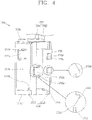
- FIG. 4 is a perspective view of the holder terminal unit 1700 illustrated in FIG. 3 .
- the holder terminal unit 1700 includes the body 1710, the body cover 1720 and the holder-side wires 1731 and 1732. Appearance of the holder terminal unit 1700 is defined by the body 1710 and the body cover 1720.
- the body 1710 has a size insertable into the rear of the shelf holding assembly 1600 (see FIGS. 1 to 3 and 6 ).
- the body 1710 as illustrated in FIG. 4 , may be formed in a hexahedral shape with an opening 1710a, but may not necessarily be limited to the hexahedral shape.
- the body 1710 may be formed in a manner of coupling a first body 1711 and a second body 1712 to each other.
- the first body 1711 forms a part of the body 1710 and the second body 1712 forms the other part of the body 1710.
- the first body 1711 forms four faces of the hexahedron except for the opening 1710a
- the second body 1712 may form one face of the hexahedron except for the opening 1710a.
- the opening 1710a is a front surface
- the first body 1711 may form upper, lower, left and rear surfaces of the hexahedron and the second body 1712 may form a right surface.
- the opening 1710a of the body 1710 is an area for an insertion of a shelf terminal unit 1900 to be explained later.
- the opening 1710a is open toward the food storage chamber 1200 illustrated in FIG. 1 .
- a protruded coupling portion 1711c is formed on an upper end of the body 1710 and a recessed coupling portion 1711c' may be formed on a lower end of the body 1710.
- the positions of the protruded coupling portion 1711 c and the recessed coupling portion 1711 c' may be switched with each other.
- the protruded coupling portion 1711 c and the recessed coupling portion 1711c' are components for mutual coupling between two different holder terminal units 1700.
- the body 1710 is provided with shelf holder coupling protrusions 1711 a and 1712a on both side surfaces. Cut portions 1711a' and 1712a' each having a shape like ' ' are formed on the both side surfaces of the body 1710, and the shelf holder coupling protrusions 1711a and 1712a each in a cantilevered shape are formed.
- the shelf holder coupling protrusions 1711a and 1712a may protrude from the side surfaces of the first body 1711 and the second body 1712 in a direction of getting away from the side surfaces and thus form steps from the side surfaces of the body 1710.
- the shelf holder coupling protrusions 1711a and 1712a can be inserted or locked in the terminal unit coupling hole 1621a, 1621b, 1621c, 1621 d, 1621e, 1621f (see FIG. 3 ) and a terminal unit coupling hole 1622a, 1622b, 1622c, 1622d, 1622e, 1622f to be explained with reference to FIG. 6 .
- each of the shelf holder coupling protrusions 1711a and 1712a may have a tilt on an outer surface thereof to be easily inserted into the shelf holding assembly 1600 (see FIGS. 1 to 3 and 6 ).
- the two shelf holder coupling protrusions 1711 a and 1712a are pushed in a direction of getting close to each other by the inner side surfaces of the shelf holding assembly 1600.
- the tilts of the shelf holder coupling protrusions 1711a and 1712a can prevent the introduction of the holder terminal unit 1700 from being interfered due to the shelf holding assembly 1600.
- the shelf holder coupling protrusions 1711 a and 1712a are inserted up to positions facing the terminal unit coupling holes 1621a, 1621b, 1621c, 1621d, 1621e, 1621f, 1622a, 1622b, 1622c, 1622d, 1622e and 1622f of the shelf holding assembly 1600, the pushed shelf holder coupling protrusions 1711a and 1712a are inserted into the terminal unit coupling holes 1621a, 1621b, 1621c, 1621d, 1621e, 1621f, 1622a, 1622b, 1622c, 1622d, 1622e and 1622f.
- the steps of the shelf holder coupling protrusions 1711a and 1712a are locked on inner circumferential surfaces of the terminal unit coupling holes 1621a, 1621b, 1621c, 1621d, 1621e, 1621f, 1622a, 1622b, 1622c, 1622d, 1622e and 1622f, and the holder terminal unit 1700 is coupled to the shelf holding assembly 1600.
- the two shelf holder coupling protrusions 1711a and 1712a which are exposed through the terminal unit coupling holes 1621a, 1621b, 1621c, 1621d, 1621e, 1621f, 1622a, 1622b, 1622c, 1622d, 1622e and 1622f are pushed to be close to each other to unlock the steps. Accordingly, in the closely-pushed state of the shelf holder coupling protrusions 1711a and 1712a, the body 1710 is pulled away from the rear of the shelf holding assembly 1600.
- the two shelf hold coupling protrusions 1711a and 1712a may be formed at different heights.
- the two shelf holder coupling protrusions 1711a and 1712a with the different heights allow for identifying left and right sides of the holder terminal unit 1700.
- the user can identify the left and right sides of the holder terminal unit 1700. This may prevent the holder terminal unit 1700 from being coupled to the shelf holding assembly 1600 in a turned-over state.
- the terminal unit coupling holes 1621a, 1621b, 1621c, 1621d, 1621e and 1621f which are formed on the left portion 1621 of the shelf holding assembly 1600 are formed at heights corresponding to the shelf holder coupling protrusion 1711a which is formed on the left surface of the body 1710.
- the terminal unit coupling holes 1622a, 1622b, 1622c, 1622d, 1622e and 1622f which are formed on the right portion 1622 of the shelf holding assembly 1600 are formed at heights corresponding to the shelf holder coupling protrusion 1711a which is formed on the right surface of the body 1710.
- the body 1710 is provided with drain holes 1711b and 1712b through which water filled or condensed in the body 1710 is drained out. Since moisture is always present in the refrigerator 1000, condensed water may be generated when internal temperature of the food storage chamber 1200 is dropped below the dew point. This may also be caused in the holder terminal unit 1700. The opening 1710a of the holder terminal unit 1700 is obscured by the cover 1750 (see FIGS. 2 and 7 ), it is impossible to fundamentally prevent water from being collected in the body 1710.
- the drain holes 1711b and 1712b allow the inside and outside of the body 1710 to communicate with each other.
- the drain holes 1711b and 1712b are preferably formed on the both side surfaces of the body 1710. This is because the front surface (i.e., the opening 1710a) of the body 1710 is obscured by the cover 1750 illustrated in FIG. 2 and the holder-side wire 1730 is disposed on the rear surface of the body 1710.
- the drain holes 1711b and 1712b are formed in order to drain out water which is likely to cause a defect of an electric contact between the holder terminal unit 1700 and the shelf terminal unit 1900. Therefore, it is not preferable to drain water out toward the holder-side wire 1730.
- the drain holes 1711b and 1712b are preferably formed on the lower portion of the body 1710, as illustrated in FIG. 4 .
- the drain holes 1711b and 1712b are preferably formed at positions in parallel to or lower than the bottom surface of the body 1710. In this instance, the positions in parallel to or lower than the bottom surface correspond to the lower portion of the body 1710.
- the protruded coupling portion 1711 c protrudes from an upper end of the body 1710 in a tilted state.
- the recessed coupling portion 1711c' is recessed into a lower end of the body 1710 in a tilted state to correspond to the protruded coupling portion 1711c.
- the two holder terminal units 1700 may be coupled to each other in a manner that the protruded coupling portion 1711 c of one of the two holder terminal units 1700 is inserted into the recessed coupling portion 1711c' of the other holder terminal unit 1700.
- the coupling of the two holder terminal units 1700 may be implemented in a manner that the protruded coupling portion 1711 c is inserted into the recessed coupling portion 1711c' in a sliding manner.
- the protruded coupling portion 1711c and the recessed coupling portion 1711c' may not always have to have the tilted shape.
- the protruded coupling portion 1711 c and the recessed coupling portion 1711 c' may not be limited to any shape if the two holder terminal units 1700 can be coupled to each other.
- the protruded coupling portion 1711c and the recessed coupling portion 1711c' may also have a shape like an alphabet 'T', in addition to the tilted shape.
- the body 1710 is coupled to the body cover 1720.
- the body 1710 is provided with body cover coupling protrusions 1712d (and 1711d illustrated in FIG. 7 ) on outer side surfaces thereof, in order to be coupled to the body cover 1720.
- the body cover coupling protrusions 1712d protrude from both (outer) side surfaces of the body 1710.
- the body cover coupling protrusions 1711d which are formed on the left side surface of the body 1710 are illustrated in FIG. 7 .
- the body cover coupling protrusions 1711d and 1712d may form steps from the side surfaces of the body 1710, to be inserted and locked in body coupling holes 1722a (see FIG. 7 ) and 1723a of the body cover 1720.
- the body cover coupling protrusions 1711d and 1712d each may be formed in a cantilevered shape, similar to the shelf holder coupling protrusions 1711a and 1712a. Also, unlike the shelf holding assembly 1600, a left cover portion 1722 and a right cover portion 1723 (see FIG. 7 ) of the body cover 1720 may be open in a direction of getting away from each other, and thus the body cover coupling protrusions 1711d and 1712d may also protrude from the outer side surfaces of the body 1710, instead of having the cantilevered shape.
- the body cover coupling protrusions 1711 d and 1712d may be tilted, similar to the shelf holder coupling protrusions 1711 a and 1712a.
- the body cover 1720 covers the body 1710.
- the body cover 1720 may be formed in a shape like ' ' to surround the both side surfaces and the rear surface of the body 1710.
- the body cover 1720 is coupled to the body 1710 with interposing the holder-side wire 1730 therebetween, so as to fix the holder-side wire 1730.
- the body cover 1720 is provided with body coupling holes 1723a and 1722a (see FiG. 7 ) on both side surfaces thereof to correspond to the body cover coupling protrusions 1711d and 1712d (see FIG. 7 ).
- the body coupling holes 1722a and 1723a may partially accommodate the body cover coupling protrusions 1711 d and 1712d, respectively, to lock the body cover coupling protrusions 1711 d and 1712d.
- the coupling between the body cover 1720 and the body 1710 is similar to the coupling between the body 1710 and the shelf holding assembly 1600.
- both side surfaces of the shape like ' ' are open in a direction of getting away from each other.
- the body cover coupling protrusions 1711 d and 1712d are tilted, the body cover 1720 may continuously be moved close to the body 1710, without the interference with the body cover coupling protrusions 1711d and 1712d.
- the body cover coupling protrusions 1711d and 1712d are locked in the body coupling holes 1722a and 1723a, and the both side surfaces of the body cover 1720 which have been open are closed and thus the body cover 1720 is restored to its original state. Accordingly, the body cover 1720 and the body 1710 are coupled to each other.
- the holder-side wire 1730 is disposed at the rear of the body 1710.
- the holder-side wire 1730 is covered by the body cover 1720. Accordingly, the holder-side wire 1730 is disposed between the body 1710 and the body cover 1720.
- the holder-side wire 1730 is connected to the power supply unit (not illustrated) of the refrigerator main body 1100.
- the holder-side wire 1730 includes two holder-side wires 1731 and 1732 which are connected to a positive (+) pole and a negative (-) pole of the power supply unit, respectively.
- FIG. 5 is a conceptual view of the holder terminal unit 1700 illustrated in FIG. 4 , viewed from a different direction.
- a holder-side terminal 1740 is coupled to the body 1710.
- the holder-side terminal 1740 is fixed to the body 1710 and partially exposed to the inside of the body 1710.
- the holder-side terminal 1740 includes two holder-side terminals 1741 and 1742 which are partially connected to the two holder-side wires 1731 and 1732 through the body 1710. If the two holder-side terminals 1741 and 1742 are referred to as a first hoider-side terminal 1741 and a second holder-side terminal 1742 and the two holder-side wires 1731 are referred to as a first holder-side wire 1731 and a second holder-side wire 1732, the first holder-side terminal 1741 is connected to the first holder-side wire 1731 and the second holder-side terminal 1742 is connected to the second holder-side wire 1732.
- the first holder-side terminal 1741 and the second holder-side terminal 1742 may be disposed with being spaced apart from each other in an up and down direction. A detailed structure of the two holder-side terminals 1741 and 1742 will be described later with reference to FIG. 8 .
- the holder-side terminal 1740 is spaced apart from a bottom surface of the body 1710.
- the holder-side terminal 1740 is disposed at a higher position than the bottom surface of the body 1710.
- the holder-side terminal 1740 has a height difference (h) from the bottom surface of the body 1710.
- water may be likely to be filled within the body 1710.
- a defective electric contact may be caused.
- the holder-side terminal 1740 is spaced apart from the bottom surface of the body 1710, the contact of the holder-side terminal 1740 with the water can be prevented.
- the water filled in the body 1710 can be drained out through the drain holes 1711b and 1712b.
- the body 1710 is provided with through holes 1711e and 1711f through which the two holder-side terminals 1741 and 1742 are inserted.
- the through holes 1711e and 1711f communicate from inside to outside of the body 1710 through the rear surface of the body 1710.
- the holder-side terminals 1741 and 1742 may be exposed to the rear surface of the body 1710 through the through holes 1711e and 1711f.
- the through holes 1711e and 1711f are formed such that the holder-side terminal 1740 in the shape like ' ' is inserted therethrough.
- the upper through hole 1711e of the two through holes 1711e and 1711f has an area which additionally communicates with the inside and outside of the body 1710 in an upward direction.
- the lower through hole 1711f of the two through holes 1711e and 1711f has an area which additionally communicates with the inside and outside of the body 1710 in a downward direction.
- the additionally-communicating areas are areas through which stopping portions 1741d and 1742d (see FIGS. 6 and 8 ) of the holder-side terminal pass. The stopping portions 1741d and 1742d of the holder-side terminal 1740 will be described later.
- FIG. 6 is a longitudinal view of the shelf holding assembly 1600 and the holder terminal unit 1700, taken along the line A-A of FIG. 2 and viewed from a side surface.
- the right portion 1622 of the shelf holding assembly 1600 can be visually viewed.
- the right portion 1622 of the shelf holding assembly 1600 is bent from the front portion 1610 of the shelf holding assembly 1600 toward the rear wall 1622 of the food storage chamber 1200.
- the right portion 1622 of the shelf holding assembly 1600 extends in the up and down direction, similar to the front portion 1610 of the shelf holding assembly 1600.
- the right portion 1622 of the shelf holding assembly 1600 is also provided with the terminal unit coupling holes 1622a, 1622b, 1622c, 1622d, 1622e and 1622f.
- the terminal unit coupling holes 1622a, 1622b, 1622c, 1622d, 1622e and 1622f are spaced apart from one another in an up and down direction.
- the terminal unit coupling holes 1622a, 1622b, 1622c, 1622d, 1622e and 1622f are arranged at the same position in a left and right direction.
- the terminal unit coupling holes 1622a, 1622b, 1622c, 1622d, 1622e and 1622f are not misaligned with one another. Therefore, the location of the holder terminal unit 1700 may change based on to which of the terminal unit coupling holes 1622a, 1622b, 1622c, 1622d, 1622e and 1622f the holder terminal unit 1700 is coupled.
- the holder terminal unit 1700 is coupled to the shelf holding assembly 1600, and the holder terminal unit 1700 is disposed at a location corresponding to the hole 1612b of the shelf holding assembly 1600. Accordingly, the two holder-side terminals 1741 and 1742 are disposed to face the hole 1612b which is formed on the front portion 1610 of the shelf holding assembly 1600.
- each of the holder-side terminals 1741 and 172 has a section in a shape like ' '
- the through holes 1711e and 1711f of the body 1710 may be formed in a shape like ' ' to correspond to the holder-side terminals.
- the body 1710 is provided with terminal coupling portions 1711g and 1711h disposed on the rear surface and extending in a left and right direction.
- the shapes of the terminal coupling portions 1711 g and 1711 h are not sufficiently illustrated in the longitudinal view of FIG. 6 , referring to FIGS. 5 and 6 , it can be predicted that the terminal coupling portions 1711g and 1711h extend in the left and right direction.
- the through holes 1711e and 1711f are formed on peripheries of the terminal coupling portions 1711 g and 1711 h.
- the holder-side terminals 1741 and 1742 surround front, upper and lower sides of the terminal coupling portions 1711 g and 1711h.
- the holder-side terminals 1741 and 1742 extend toward the rear surface of the body 1710. Specifically, the holder-side terminals 1741 and 1742 extend up to the outside of the body 1710, bent at the outside of the body 1710, and locked on the rear surface of the body 1710.
- the stopping portion 1741d of the first holder-side terminal 1741 is bent upwardly to be locked on the rear surface of the body 1710.
- the stopping portion 1742d of the second holder-side terminal 1742 is bent downwardly to be locked on the rear surface of the body 1710.
- the holder-side terminals 1741 and 1742 should maintain an electrically-connected state with the holder-side wires 1731 (see FIGS. 2 to 5 and 7 to 8 ) and 1732, and the locations of the holder-side terminals 1741 and 1742 should be fixed although a physical impact is applied thereto during mounting of the shelf terminal unit 1900.
- widths of the holder-side terminals 1741 and 1742 in the up and down direction are smaller than widths of the terminal coupling portions 1711g and 1711 h in the up and down direction, the holder-side terminals 1741 and 1742 are affected by force in a direction of getting open due to the terminal coupling portions 1711g and 1711h. Therefore, the locations of the holder-side terminals 1741 and 1742 can be fixed. Also, as the stopping portions 1741d and 1742d of the holder-side terminals 1741 and 1742 are locked on the rear surface of the body 1710, the locations of the holder-side terminals 1741 and 1742 can be fixed.
- FIG. 7 is a disassembled perspective view of the shelf holding assembly 1600 and the holder terminal unit 1700.
- the body cover 1720 includes a rear surface cover portion 17201, a left cover portion 1722 and a right cover portion 1723.
- the rear surface cover portion 1721 covers the rear surface of the body 1710.
- the rear surface cover portion 1721 is disposed to face the rear surface of the body 1710.
- the rear surface cover portion 1721 is provided with wire receiving grooves 1721a and 1721b.
- the wire receiving grooves 1721a and 1721b of the rear surface cover portion 1721 are formed by being recessed at locations facing the rear surface of the body cover 1720 to correspond to appearance of the two holder-side terminals 1731 and 1732.
- the wire receiving grooves 1721a and 1721b of the rear surface cover portion 1721 may extend in an up and down direction along an extending direction of the two holder-side wires 1731 and 1732.
- the two holder-side wires 1731 and 1732 may partially or all be received in the wire receiving grooves 1721a and 1721b of the rear surface cover portion 1721.
- the body 1710 may also be provided with wire receiving grooves (not illustrated) at locations corresponding to the wire receiving grooves 1721a and 1721b of the body cover 1720.
- the wire receiving grooves of the body 1710 form an arrangement space of the two hoider-side wires 1731 and 1732 together with the wire receiving grooves 1721a and 1721 b of the body cover 1720.
- the rear surface cover portion 1721 is provided with location fixing protrusions 1721c.
- the location fixing protrusions 1721c protrude from peripheries of the wire receiving grooves 1721a and 1721b.
- the location fixing protrusions 1721c may be formed on upper and lower ends of the rear surface cover portion 1721, as illustrated in FIG. 7 .
- the present invention may not be limited to this.
- the location fixing protrusions 1721c may be formed on any locations of the peripheries of the wire receiving grooves 1721a and 1721b.
- each holder-side wire 1731 and 1732 is thick in thickness, the rear surface of the body 1710 and the rear surface cover portion 1721 may be spaced apart from each other and the holder-side wires 1731 and 1732 may be likely to be separated from the wire receiving grooves 1721a and 1721b and the wire receiving grooves (not illustrated) of the body 1710.
- the location fixing protrusions 1721c restrict the movements of the holder-side wires 1731 and 1732 at the left and right sides of the holder-side wires 1731 and 1732, the locations of the holder-side wires 1731 and 1732 may be fixed.
- the left cover portion 1722 covers the left surface of the body 1710.
- the right cover portion 1723 covers the right surface of the body 1710.
- the left cover portion 1722 and the right cover portion 1723 extend from the rear surface cover portion 1721 in a direction in parallel to the side surface of the body 1710.
- a reinforcing rib (not illustrated) may be provided on a connected portion between the left cover portion 1722 and the rear surface cover portion 1721.
- a reinforcing rib 1723b may also be provided on a connected portion between the right cover portion 1723 and the rear surface cover portion 1721.
- the reinforcing rib 1723b may be additionally attached to the connected portion between the rear surface cover portion 1721 and the left cover portion 1722 or to the connected portion between the rear surface cover portion 1721 and the right cover portion 1723.
- the reinforcing rib 1723b may be integrally formed with the body cover 1720.
- the left cover portion 1722 and the right cover portion 1723 may be liked to be cut off from the rear surface cover portion 1721.
- the reinforcing rib 1723b can solve such concern by reinforcing the connection between the rear surface cover portion 1721 and the left cover portion 1722 and the connection between the rear surface cover portion 1721 and the right cover portion 1723.
- the left cover portion 1722 and the right cover portion 1723 are provided with body coupling holes 1722a and 1723a, respectively.
- the insertion and lock of the body cover coupling protrusions 1711d and 1712d into the body coupling holes 1722a and 1723a have been described above.
- the holder-side terminals 1741 and 1742 are inserted through the body 1710 and exposed to the rear surface of the body 1710. Since the holder-side wires 1731 and 1732 are disposed at the rear surface of the body 1710, the holder-side terminals 1741 and 1742 exposed to the rear surface of the body 1710 are brought into contact with the holder-side wires 1731 and 1732.
- the holder-side wires 1731 and 1732 are provided with coating members 1731b and 1732b (see FIG. 8 ) for insulation, and conductive members 8131c and 1732c (see FIG. 8 ) within the coating members 1731b and 1732b, respectively. Therefore, in order for the holder-side terminals 1741 and 1742 to be connected to the power supply unit of the refrigerator main body 1100 (see FIG. 1 ) through the holder-side wires 1731 and 1732, the holder-side terminals 1741 and 1742 should be brought into contact with the conductive members 1731c and 1732c of the hoider-side wires 1731 and 1732.
- the holder-side terminals 1741 and 1742 are partially inserted into the coating members 1731b and 1732b of the holder-side wires 1731 and 1732.
- the inserted portions of the holder-side terminals 1741 and 1742 may be brought into contact with the conductive members 1731c and 1732c.
- FIG. 7 illustrates a state that the holder-side terminals 1741 and 1742 are inserted into the coating members 1731b and 1732b of the holder-side wires 1731 and 1732 and then are separated from the holder-side wires 1731 and 1732 again.
- the coating member 1731b of the first holder-side wire 1731 is partially damaged and the conductive member 1731 c within the coating member 1731b is visually exposed to outside. It can be noticed at a portion indicated with a reference numeral 1731a.
- the coating member 1732b of the second holder-side wire 1732 is partially damaged and the conductive member 1732c within the coating member 1732b is visually exposed to outside. It can be noticed at a portion indicated with a reference numeral 1732a.
- a cover 1750 is disposed between the body 1710 and the shelf holding assembly 1600.
- the cover 1750 extends in the up and down direction, similar to the shelf holding assembly 1600.
- the opening 1710a is formed at the front surface of the body 1710, and the shelf holding assembly 1600 is provided with the hole 1612b corresponding to the opening 1710a of the body 1710. Therefore, the holder-side terminals 1741 and 1742 may be exposed to the food storage chamber 1200 (see FIG. 1 ) through the hole 1612b and the opening 1710a. When the holder-side terminals 1741 and 1742 are exposed to the food storage chamber 1200, it may be affected by moisture and also exposed to a physical impact.
- the cover 1750 is configured to block the opening 1710a of the body 1710 and the hole 1612b of the shelf holding assembly 1600. Since the cover 1750 blocks the opening 1710a of the body 1710 and the hole 1612b of the shelf holding assembly 1600, a direct exposure of the holder-side terminals 1741 and 1742 to the moisture or the physical impact can be prevented.
- the cover 1750 includes a cut portion 1752 through which a shelf terminal unit 1900 to be explained later is inserted.
- the cut portion 1752 may be formed in a shape of a straight line extending in a vertical direction, or in a shape of additionally extending along a horizontal direction from both end portions of the vertically-extended line.
- the cut portion 1752 may be formed in a shape like ' ' as illustrated in FIG. 7 .
- the cover 1750 includes a door 1751 in a cantilevered shape.
- the shelf terminal unit 1900 to be explained later can be prevented from being caught in the cover 1750.
- the door 1751 which has the cantilevered shape may thus be pushed inwardly by the shelf terminal unit 1900.
- the door 1751 may receive external force by the shelf terminal unit 1900.
- a free end of the door 1751 may be moved and the fixed end of the door 1751 is fixed to the other portion of the cover 1750. Accordingly, the door 1751 can be pushed inwardly by the external force. It can be guessed based on FIG. 7 that the door 1751 is to be pushed inwardly toward the left surface of the body 1710.
- the cover 1750 is preferably formed of an elastic material.
- a location setting groove 1753 is formed on the front surface of the cover 1750.
- the shelf holding assembly 1600 is provided with a protrusion (not illustrated) corresponding to the location setting groove 1753 of the cover 1750.
- the protrusion of the shelf holding assembly 1600 is formed on a surface facing the cover 1750.
- a location where the protrusion of the shelf holding assembly 1600 is inserted into the location setting groove 1753 of the cover 1750 corresponds to a coupling location between the cover 1750 and the shelf holding assembly 1600.
- the holder-side terminals 1741 and 1742 coupled to the body 1710 are electrically connected to the holder-side wires 1731 and 1732, and the holder terminal unit 1700 is implemented accordingly.
- the holder terminal unit 1700 is coupled to the shelf holding assembly 1600 with the cover 1750 interposed therebetween, a preparation for an electric connection with the shelf terminal unit 1900 to be explained later is completed.
- FIG. 8 is a perspective view of the holder-side terminals 1741 and 1742 illustrated in FIG. 7 .
- the holder-side terminal 1740 includes the first holder-side terminal 1741 and the second holder-side terminal 1742.
- the first holder-side terminal 1741 is electrically connected to the first holder-side wire 1731
- the second holder-side terminal 1742 is electrically connected to the second holder-side wire 1732.
- the first holder-side terminal 1741 and the second holder-side terminal 1742 may have the same shape.
- the second holder-side terminal 1742 may have the shape that the first holder-side terminal 1741 is turned over.
- the holder-side terminal 1740 should be understood as a concept including both of the first holder-side terminal 1741 and the second holder-side terminal 1742.
- the first and second holder-side terminals 1741, 1742 include front contact portions 1741a, 1742a, first extending portions 1741b, 1742b, second extending portions 1741c, 1742c, stopping portions 1741d, 1742d, recessed portions 1741e, 1742e, 1742f, and wire receiving portions 1741g, 1741h, 1742h, respectively.
- the front contact portions 1741a and 1742a are exposed to the inside of the body 1710 (see FIGS. 3 to 7 ).
- the front contact portions 1741 a and 1742a are disposed on front surfaces of the terminal coupling portions 1711g and 1711h (see FIG. 6 ), and obscure the front surfaces of the terminal coupling portions 1711g and 1711 h. Accordingly, when viewing the inside of the holder terminal unit 1700 through the opening 1710a of the body 1710, the front contact portions 1741a and 1742a can be viewed (see FIG. 5 ).
- the first extending portions 1741b and 1742b are bent from the front contact portions 1741a and 1742a and extend toward the rear surface of the body 1710.
- the second extending portions 1741 c and 1742c are also bent from the front contact portions 1741a and 1742a and extend toward the rear surface of the body 1710.
- the first extending portions 1741b and 1742b and the second extending portions 1741c and 1742c are disposed to face each other.
- the front contact portions 1741a and 1741a, the first extending portions 1741b and 1742b and the second extending portions 1741c and 1742c are coupied to the terminal coupling portions 1711 g and 1711 h (see FIG. 6 ), in a surrounding manner.
- One side of each of the second extending portions 1741c and 1742c may extend longer than each of the first extending portions 1741b and 1742b, so as to prevent separation of the holder-side wires 1731 and 1732 which are received in the wire receiving portions 1741g, 1741 h and 1742h.
- the stopping portions 1741d and 1742d are bent and extend from the first extending portions 1741b and 1742b.
- the extending direction of the stopping portions 1741d and 1742d may be a direction in parallel to the front contact portions 1741a and 1742a.
- Arranged locations of the stopping portions 1741d and 1742d correspond to the rear surface of the body 1710.
- the stopping portions 1741d and 1742d are locked (stopped) on the rear surface of the body 1710. As the stopping portions 1741d and 1742d are locked on the rear surface of the body 1710, the holder-side terminals 1741 and 1742 can be prevented from being moved into the body 1710.
- the first extending portions 1741b and 1742b and the second extending portions 1741c and 1742c are provided with the recessed portions 1741e, 1742e and 1742f.
- the recessed portions 1741e, 1742e and 1742f have peripheries smaller than the holder-side wires 1731 and 1732.
- the peripheries of the recessed portions 1741 e, 1742e and 1742f are smaller than the peripheries of the coating members 1731 b and 1732b of the holder-side wires 1731 and 1732.
- the recessed portions 1741e, 1742e and 1742f are inserted into the coating members 1731b and 1732b of the hoider-side wires 1731 and 1732 and thus are brought into contact with the conductive members 1731 c and 1732c within the coating members 1731b and 1732b.
- the recessed portions 1741e, 1742e and 1742f are formed on the first extending portions 1741b and 1742b and the second extending portions 1741c and 1742c, it can be known that the recessed portions 1741e, 1742e and 1742f electrically come in contact with the conductive members 1731c and 1732c of the holder-side wires 1731 and 1732 at the first extending portions 1741b and 1742b and the second extending portions 1741 c and 1742c.
- the recessed portions 1741e and the 1742e formed on the first extending portions 1741b and 1742b and the recessed portions 1742f formed on the second extending portions 1741c and 1742c are formed at the same side based on the stopping portions 1741d and 1742d.
- the recessed portion 1741e formed on the first extending portion 1741b and the recess portion 1742e formed on the second extending portion 1741c are all disposed at the left side based on the stopping portion 1741d. Therefore, the first holder-side terminal 1741 electrically comes in contact with the conductive member 1731c of the first holder-side wire 1731 at the left side of the stopping portion 1741d.
- the second holder-side terminal 1742 electrically comes in contact with the conductive member 1732c of the second holder-side wire 1732 at the right side of the stopping portion 1742d.
- the first extending portions 1741b and 1742b and the second extending portions 1741c and 1742c are provided with wire receiving portions 1741g, 1741h and 1742h, respectively.
- the wire receiving portions 1741g, 1741h and 1742h have peripheries greater than the recess portions 1741e, 1742e and 1742f.
- the wire receiving portions 1741g, 1741h and 1742h preferably have peripheries which are the same as or greater than those of the coating members 1731b and 1732b of the holder-side wires 1731 and 1732.
- the holder-side terminals 1741 and 1742 merely come in contact with the coating members 1731b and 1732b, without being inserted into the coating members 1731b and 1732b. Therefore, an electric insulation between the holder-side terminals 1741 and 1742 and the holder-side wires 1731 and 1732 is maintained at the wire receiving portions 1741 g, 1741h and 1742h.
- the wire receiving portions 1741g formed on the first extending portions 1741b and 1742b and the wire receiving portions 1741h and 1742h formed on the second extending portions 1741c and 1742c are located at the same side based on the stopping portions 1741d and 1742d.
- the wire receiving portions 1741g formed on the first extending portions 1741b and 1742b and the wire receiving portions 1741 h and 1742h formed on the second extending portions 1741c and 1742c are located at the right side based on the stopping portion 1741d.
- the electric insulation between the first holder-side terminal 1741 and the second holder-side wire 1732 is maintained at the right side of the stopping portion 1741d.
- the electric insulation between the second holder-side terminal 1742 and the first holder-side wire 1731 is maintained at the right side of the stopping portion 1742d.
- the first holder-side terminal 1741 is electrically connected with the first holder-side wire 1731 and electrically insulated from the second holder-side wire 1732.
- the second holder-side wire 1742 is electrically connected with the second holder-side wire 1732 and electrically insulated from the first holder-side wire 1731.
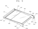
- FIG. 9 is a perspective view of the shelf assembly 1800 and the shelf terminal unit 1900
- FIG. 10 illustrates a disassembled perspective view of the shelf assembly 1800 illustrated in FIG. 9 , and a conceptual view of the shelf terminal unit 1900.
- the shelf assembly 1800 includes a shelf portion 1810.
- the shelf portion 1810 is formed in a shape of a plate on which foods and the like are kept.
- the shelf portion 1810 may be made of a transparent material for ensuring visibility in an up and down direction.
- the shelf portion 1810 may be made of glass or transparent plastic.
- the shelf assembly 1800 includes frames 1821, 1822, 1823 and 1824.
- the frames 1821, 1822, 1823 and 1824 include a front frame 1821, a rear frame 1822, the left frame 1823 and a right frame 1824.
- the front side is defined as a portion of the shelf assembly 1800, which is located close to a user, based on a direction that the user views the food storing chamber 1200.
- the left and right sides are also defined based on a direction that the user views the food storage chamber 1200.
- the rear side refers to a portion of the shelf assembly 1800 which is close to the shelf holding assembly 1600.
- the shelf portion 1810 is made of glass or plastic, the shelf portion 1810 may be likely to be broken due to an impact.
- the front frame 18221, the rear frame 1822, the left frame 1823 and the right frame 1824 are provided to protect edges of the shelf portion 1810 from impacts, respectively.
- the front frame 1821, the rear frame 1822, the left frame 1823 and the right frame 1824 have lengths corresponding to the edges of the shelf portion 1810, respectively.
- the front frame 1821 is coupled to the front edge of the shelf portion 1810, and the rear frame 1822 is coupled to the rear edge of the shelf portion 1810.
- the left frame 1823 is coupled to the left edge of the shelf portion 1810
- the right frame 1824 is coupled to the right edge of the shelf portion 1810.
- the front frame 1821, the rear frame 1822, the left frame 1823 and the right frame 1824 may cover the edges of the shelf portion 1810 and support lower surfaces of the edges, respectively.
- the left frame 1823 and the right frame 1824 are disposed on brackets 1831 and 1832.
- the left frame 1823 and the right frame 1824 cover upper portions of the brackets 1831 and 1832.
- the left frame 1823 and the right frame 1824 have mounting protrusions 1823a and 1824a at the rear thereof, respectively.
- the mounting protrusions 1823a and 1824a protrude from the rear sides of the left frame 1823 and the right frame 1824, respectively. Since the mounting protrusions 1823a and 1824a are provided to be mounted to the brackets 1831 and 1832, they protrude downwardly toward the brackets 1831 and 1832.
- the coupling between the left and right frames 1831 and 1832 and the brackets 1831 and 1832 may alternatively be implemented by using coupling members (not illustrated), such as bolts, instead of the mounting protrusions 1823a and 1824a.
- the brackets 1831 and 1832 are installed beneath the shelf portion 1810 to support the shelf portion 1810.
- the brackets 1831 and 1832 includes a left bracket 1831 and a right bracket 1832.
- the left bracket 1831 and the right bracket 1832 may directly support the shelf portion 1810 or indirectly support the shelf portion 1810 by supporting the left frame 1823 and the right frame 1824.
- FIGS. 9 and 10 illustrate that the left bracket 1831 supports the left frame 1823 and the right bracket 1832 supports the right frame 1824.
- brackets 1831 and 1832 extend in parallel toward the rear of the shelf portion 1810, but lower portions of the brackets 1831 and 1832 extend toward the rear of the shelf portion 1810 in a direction of getting away from the upper portion of the shelf portion 1810. Accordingly, the brackets 1831 and 1832 may generally have a shape of a right triangle, and the lower portions of the brackets 1831 and 1832 may be formed in a curved shape.
- brackets 1831 and 1832 facilitates for supporting the front and rear sides of the shelf portion 1810 when the shelf portion 1810 is mounted on the shelf holding assembly 1600.
- the shelf holding assembly 1600 is located at the rear of the shelf assembly 1800. Accordingly, when the shelf assembly 1800 is attached to the shelf holding assembly 1600, the front side of the shelf assembly 1800 is affected by a weight in a downward direction of getting close to the shelf holding assembly 1600, on the basis of the attached point.
- the brackets 1831 and 1832 have the shape that the lower portion of each bracket extends toward the rear side of the shelf portion 1810 in a direction of getting away from the upper portion of the shelf portion 1810.
- the brackets 1831 and 1832 are provided on upper portions thereof with first receiving grooves 1831 a and 1832a and second receiving grooves 1831b and 1832b.
- the first receiving grooves 1831 a and 1832a and the second receiving grooves 1831b and 1832b are formed in a manner of being recessed into the upper portions of the brackets 1831 and 1832.
- the first receiving grooves 1831 a and 1832a are formed on the front portions of the brackets 1831 and 1832.
- the first receiving grooves 1831 a and 1832a receive a part of a cap 1870 or a part of a wire cover 1860 to be explained later, so as to support the cap 1870 or the wire cover 1860.
- the second receiving grooves 1831b and 1832b are formed on the rear portions of the brackets 1831 and 1832.
- the second receiving grooves 1831b and 1832b receive the mounting grooves 1823a and 1824a of the left frame 1823 and the right frame 1824, so as to support the mounting protrusions 1823a and 1824a.
- the brackets 1831 and 1832 are provided on rear end portions thereof with hook portions 1831c and 1832c and inserting portions 1831d and 1832d, respectively.
- the hook portions 1831c and 1832c and the inserting portions 1831d and 1832d are components required for attaching the shelf assembly 1800 to the shelf holding assembly 1600.
- the hook portions 1831c and 1832c are located more above the inserting portions 1831d and 1832d, and on the other hand, the inserting portion 1831d and 1832d are located more below the hook portions 1831 c and 1832c.
- the hook portions 1831c and 1832c protrude from the rear sides of the brackets 1831 and 1832 toward the holes 1612a, 1612b and 1612c (see FIGS. 2 , 6 and 7 ) of the shelf holding assembly 1600, and extend downwardly to be mounted on the shelf supporting portions 1611 (see FIGS. 2 , 6 and 7 ) of the shelf holding assembly 1600.
- the hook portions 1831c and 1832c are inserted into the holes 1612a, 1612b and 1612c and mounted on the shelf supporting portions 1611.
- the inserting portions 1831 d and 1832d protrude from the rear sides of the brackets 1831 and 1832 toward the holes 1612a, 1612b and 1612c (see FIGS. 2 , 6 and 7 ) of the shelf holding assembly 1600.
- the inserting portions 1831d and 1832d are inserted into the holes 1612a, 1612b and 1612c and mounted on the shelf supporting portions 1611.
- the shelf assembly 1800 may include bars 1833 and 1834 disposed between the left bracket 1831 and the right bracket 1832.
- the bars 1833 and 1834 may be installed at front and rear sides of the brackets 1831 and 1832.
- Each of the bars 1833 and 1834 extend in a horizontal direction.
- One end of each bar 1833 and 1834 is connected to the left bracket 1831 and another end of each bar 1833 and 1834 is connected to the right bracket 1832.
- Each bar 1833 and 1834 supports surfaces of the left bracket 1831 and the right bracket 1832 that face each other.
- the shelf assembly 1800 includes a lighting device 1840 that lights up the food storage chamber 1200 (see FIG. 1 ).
- the lighting device 1840 described herein may include every component, such as a fluorescent light, an incandescent light, a light-emitting device (LED), or the like, which emits light.
- the lighting device 1840 may include a liquid crystal display (LCD) device providing visual information by a backlight unit, and also include a light guiding member for guiding light.
- LCD liquid crystal display
- the present invention may not be limited to any specific shape or type of the lighting device 1840.
- the lighting device 1840 is installed at the front of the shelf assembly 1800. If the lighting device 1840 is disposed on an upper surface of the shelf portion 1810, light generated from the lighting device 1840 may be likely to be transferred directly to the user at a too close location to the user. Therefore, the lighting device 1840 is preferably disposed on a lower surface of the shelf portion 1810.
- a lighting device cover 1850 accommodates the lighting device 1840.
- the lighting device cover 1850 similar to the front frame 1821, may extend in a left and right direction and the lighting device 1840 may be disposed within the lighting device cover 1850.
- the lighting device cover 1850 is installed beneath the shelf portion 1810.
- the cap 1870 and the wire cover 1860 are coupled to both ends of the lighting device cover 1850, and accordingly the lighting device cover 1850 can be supported on the brackets 1831 and 1832.
- the both ends of the lighting device cover 1850 may be open such that the lighting device cover 1850 can be coupled with the cap 1870 and the wire cover 1860.
- the shelf assembly 1800 includes the wire cover 1860 and the cap 1870 which close the both ends of the lighting device cover 1850.
- the wire cover 1860 protects the shelf-side wires 1961 and 1962 (see FIGS. 11 to 14 ).
- the shelf-side wires 1961 and 1962 are connected to the shelf terminal unit 1900 and the lighting device 1840, respectively, to electrically connect the shelf terminal unit 1900 and the lighting device 1840 to each other. Since the shelf-side wires 1961 and 1962 implement the electric connection, it is not preferable to externally expose the shelf-side wires 1961 and 1962. This is because the shelf-side wires 1961 and 1962 may be affected by a physical impact or moisture.
- the wire cover 1860 protects the shelf-side wires 1961 and 1962 from such physical impact or moisture.
- the wire cover 1860 extends from rear to front sides (or front to rear sides) of the bracket 1831, 1832 along the bracket 1831, 1832. Referring to FIG. 10 , the wire cover 1860 extends downwardly from the rear side of the left bracket 1831 along the shape of the left bracket 1831, is bent forwardly from the lower side, and then extends into a tilted shape. However, the shape of the wire cover 1860 may not be necessarily limited to this.
- the wire cover 1860 is closely adhered to an inner side surface of the left bracket 1831 or the right bracket 1832.
- the wire cover 1860 covers the shelf-side wires 1961 and 1962.
- the wire cover 1860 may have a section in a shape like ' ' and the shelf-side wires 1961 and 1962 are disposed in a space formed between the wire cover 1860 and the inner side surface of the bracket 1831, 1832.
- the wire cover 1860 may be provided with a sealing member (not illustrated) on a periphery thereof.
- the shelf terminal unit 1900 is coupled to the rear side of the wire cover 1860.
- the shelf terminal unit 1900 is disposed between the hook portion 8131c, 1832c and the inserting portion 1831d, 1832d of the bracket 1831, 1832.
- Two parts of the shelf terminal unit 1900 are coupled to each other with interposing the wire cover 1860 and the brackets 1831 and 1832 therebetween.
- This coupling structure is obviously illustrated in FIGS. 12 to 14 .
- the shelf terminal unit 1900 may be installed on the left frame 1831 and/or the right bracket 1832.
- the wire cover 1860 is coupled to the bracket (at least one of the brackets 1831 and 1832) on which the shelf terminal unit 1900 is installed.
- FiG. 10 illustrates that the wire cover 1860 is coupled to the left bracket 1831.
- FIG. 9 does not show the wire cover but it can be guessed that the wire cover is coupled to the right bracket 1832 based on the coupled state between the shelf terminal unit 1900 and the right bracket 1832.
- the wire cover 1860 is coupled to the bracket 1831, 1832 by a coupling member 1880 (see FIGS. 13 and 14 ), such as a bolt or the like, at the rear side thereof.
- the wire cover 1860 and the bracket 1831, 1832 may include coupling holes 1863 and 1831e, 1832e for insertion of the bolts or the like.
- the coupling member 1880 such as the bolt or the like may be inserted into the coupling hole 1863 of the wire cover 1860 and the coupling hole 1831e, 1832e of the brackets 1831 and 1832, such that the wire cover 18670 and the brackets 1831 and 1832 can be coupled to the each other.
- the wire cover 1860 includes a first coupling protrusion 1861 and a second coupling protrusion 1962 provided on a front portion thereof.
- the first coupling protrusion 1861 protrudes from an outer side of the wire cover 1860 toward the bracket 1831, 1832.
- the first coupling protrusion 1861 is received in the first receiving groove 1831a of the bracket 1831.
- the first coupling protrusion 1861 is mounted in the first receiving groove 1831 a of the bracket 1831 at the front of the wire cover 1860, and the rear side of the wire cover 1860 is coupled to the inner side surface of the bracket 1831, 1832 by the coupling member 1880 such as the bolt or the like. This may allow for stable coupling between the wire cover 1860 and the bracket 1831, 1832.
- the shelf-side wires 1861 and 1862 are disposed between the wire cover 1860 and the bracket 1831, 1832, so as to be protected from the physical impact or moisture.
- the second coupling protrusion 1862 protrudes from an inner side of the wire cover 1860 toward the lighting device cover 1850.
- the second coupling protrusion 1862 may be formed at a substantially opposite side to the first coupling protrusion 1861.
- the second coupling protrusion 1862 is inserted into another end of the lighting device cover 1850.
- the second coupling protrusion 1862 may be provided with a sealing member 1865 (see FIG. 11 ) on an outer circumferential surface thereof.
- the sealing member 1865 coupled to the outer circumferential surface of the second coupling protrusion 1862 may seal the lighting device cover 1850.
- the cap 1870 is partially inserted into one end of the lighting device cover 1850. A more detailed structure of the cap 1870 will be described with reference to FIG. 11 .
- FIG. 11 is a perspective view of the lighting device cover 1850, the cap 1870, the wire cover 1860 and the shelf terminal unit 1900.
- At least part of the lighting device cover 1850 is made of a transparent material 1852, in order for light generated in the lighting device 1840 inserted into the lighting device cover 1850 to light up the inside of the food storage chamber 1200.
- the lighting device cover 1850 may fully be made of the transparent material 1852, but as aforementioned, it is not preferable that the light is transferred directly to the user.
- a part of the lighting device cover 1850 may be made of the transparent material 1852, and the other part may be made of an opaque material 1853.
- an area formed of the transparent material 1852 an area of the food storage chamber 1200 to be lighted up may be set.
- FIG. 11 illustrates the opaque material 1853 (1854 also corresponds to the opaque material) with a slashed line.
- the lighting device cover 1850 is provided with an accommodating portion 1851 and a grip portion 1854.
- the accommodating portion 1851 is an area in which the lighting device cover 1850 is accommodated.
- the grip portion 1854 may extend from the accommodating portion 1851 toward the rear side and a lower side of the shelf assembly 1800 into a curved shape.
- the grip portion 1854 may have a shape of double extending from an upper end and a middle portion of the accommodating portion 1851 and connecting ends of the extended portions.
- the user grips a part of the shelf assembly 1800, and attempts to detach the shelf assembly 1800 from the shelf holding assembly 1600.
- external force may be applied to the lighting device 1840 within the accommodating portion 1851, and thereby the lighting device 1840 may be damaged.
- the grip portion 1854 extends from the accommodating portion 1851 toward the rear and lower sides of the shelf assembly 1800 into the curved shape, a space where the user situates fingers is naturally generated.
- the user who detaches the shelf assembly 1800 from the shelf holding assembly 1600 naturally situates the fingers on the grip portion 1854. Accordingly, the external force transferred by the user's fingers is concentrated on the grip portion 1854. And, the external force generated due to the user's fingers can be prevented from being transferred to the lighting device 1840 within the accommodating portion 1851.
- the cap 1870 is partially inserted into one end of the lighting device cover 1850.
- the cap 1870 includes a main body 1871, a first protrusion 1872, a stopping jaw 1873, a sealing member 1874 and a second protrusion 1875.
- the main body 1871 is disposed at an outer side of the lighting device cover 1850. Since the installation location of the main body 1871 is nearby the lighting device cover 1850, the main body 1871 may have the same section as the accommodating portion 1851 of the lighting device cover 1850.
- the first protrusion 1872, the stopping jaw 1873 and the second protrusion 1875 are all formed by protruding from the main body 1871.
- the first protrusion 1872 protrudes from the main body 1871 toward the lighting device cover 1850.
- the first protrusion 1872 is inserted into the lighting device cover 1850.
- the sealing member 1874 is coupled to an outer circumferential surface of the first protrusion 1872.
- the sealing member 1874 seals a gap between the lighting device cover 1850 and the cap 1870, thereby preventing an introduction of moisture into the lighting device cover 1850.
- the stopping jaw 1873 protrudes in a perpendicular direction to the protruding direction of the first protrusion 1872.
- the stopping jaw 1873 is formed to be locked at an inlet of the lighting device cover 1850.
- the stopping jaw 1873 prevents the cap 1870 from being excessively inserted into the lighting device 1840.
- the second protrusion 1875 protrudes from the main body 1871 toward the bracket 1831, 1832.
- the second protrusion 1875 has a size corresponding to a size of the first receiving groove 1831.
- the second protrusion 1875 is received in the first receiving groove 1831a, 1832a of the bracket 1831, 1832.
- the structure according to the present invention in which the second coupling protrusion 1862 of the wire cover 1860 is inserted into the another end of the lighting device cover 1850 can more simplify a complicated configuration and also save an unnecessary space which is generated during an assembly of the refrigerator 1000.
- the wire cover 1860 includes a first coupling protrusion 1861 and a second coupling protrusion 1862 disposed at the front side thereof.
- the first coupling protrusion 1861 protrudes from an outer side of the wire cover 1860 toward the bracket 1831, 1832.
- the first coupling protrusion 1861 is received in the first receiving groove 1831a of the bracket 1831. Since the first coupling protrusion 1861 is received in the first receiving groove 1831 a of the bracket 1831 at the front of the wire cover 1860 and the rear side of the wire cover 1860 is coupled to the inner side surface of the bracket 1831, 1832 by the coupling member 1880 such as the bolt or the like, thereby enabling stable coupling between the wire cover 1860 and the bracket 1831, 1832. Also, the shelf-side wires 1861 and 1862 are disposed between the wire cover 1860 and the bracket 1831, 1832, and accordingly can be protected from a physical impact or moisture.
- the second coupling protrusion 1862 protrudes from an inner side of the wire cover 1860 toward the lighting device cover 1850.
- the second coupling protrusion 1862 may be formed at a substantially opposite side to the first coupling protrusion 1861.
- the second coupling protrusion 1862 may be provided with a sealing member 1865 (see FIG. 11 ) on an outer circumferential surface thereof. The sealing member 1865 coupled to the outer circumferential surface of the second coupling protrusion 1862 can seal the lighting device cover 1850.
- the shelf-side wires 1961 and 1962 are protected by the wire cover 1860.
- the shelf-side wires 1961 and 1962 are inserted into the lighting device cover 1850 through the wire cover 1860.
- the shelf-side wires 1961 and 1962 are connected to the lighting device 1840 within the lighting device cover 1850. Accordingly, the electric connection between the shelf terminal unit 1900 and the lighting device 1840 can be realized.
- FIG. 12 is a disassembled perspective view of the shelf terminal unit 1900 illustrated in FIGS. 10 and 11 .
- the shelf terminal unit 1900 includes housings 1911, 1912 and 1913, pins 1921 and 1922, elastic components 1931 and 1932, contact terminals 1941 and 1942 and shelf-side wires 1961 and 1962.
- a direction that the pins 1921 and 1922 are exposed from the housings 1911, 1912 and 1913 is defined as a rear side of the shelf terminal unit 1900
- a direction that the shelf-side wires 1961 and 1962 are exposed from the housings 1911, 1912 and 1913 is defined as a front side of the shelf terminal unit 1900.
- the front and rear sides correspond to substantially the same as the front and rear sides of the shelf assembly 1300.
- the housings 1911, 1912 and 1913 include a first housing 1911, a second housing 1912, and a third housing 1913.
- the housings 1911, 1912 and 1913 are coupled to the bracket 1831, 1832 of the shelf assembly 1800.
- the housings 1911, 1912 and 1913 accommodate at least part of the pins 1921 and 1922.
- the second housing 1912 and the third housing 1913 are coupled to the first housing 1911, and the first housing 1911, the second housing 1912 and the third housing 1913 are configured to accommodate the other components of the shelf terminal unit 1900.
- the first housing 1911 includes a cover portion 1911a, a first wing portion 1911c, a coupling member inserting portion 1911 d, and second wing portions 1911f and 1911g.
- the cover portion 1911 a covers the second housing 1912.
- the cover portion 1911a also accommodates the pins 1921 and 1922, the elastic components 1931 and 1932, and the contact terminals 1941 and 1942 of the shelf terminal unit 1900.
- the cover portion 1911 a extends toward the rear of the shelf terminal unit 1900 along an extending direction of the pins 1921 and 1922.
- the pins 1921 and 1922, the elastic components 1931 and 1932 and the contact terminals 1941 and 1942 are disposed in a space between the cover portion 1911 a and the second housing 1912.
- the cover portion 1911 a includes two pin holes 1911 a' corresponding to the pins 1921 and 1922.
- the two pin holes 1911a' are open toward the shelf holding assembly 1600.
- the pins 1921 and 1922 are configured to be linearly movable in and out of the housing 1911, 1912 and 1913 through the pin holes 1911a'.
- a structure in which the first housing 1911 forms a part of the pin holes 1911a' and the second housing 1912 forms the rest of the pin holes 1911' may increase a distance between the first housing 1911 and the second housing 1912, and thereby be likely to cause a separation of the pins 1921 and 1922 from the housings 1911, 1912 and 1913.
- the structure according to the present invention in which the first housing 1911 has the pin holes 1911a' can prevent the separation of the pins 1921 and 1922 even though the distance between the first housing 1911 and the second housing 1912 increases.
- the first housing 1911 includes elastic component receiving grooves 1911a" in which the elastic components 1931 and 1932 are accommodated.
- the elastic component receiving grooves 1911 a" may be formed within the cover portion 1911a.
- the elastic component receiving grooves 1911a" preferably form spaces in a shape of a semicircular pillar corresponding to the elastic components 1931 and 1932. If the elastic component receiving grooves 1911 a" form a space in a polygonal shape, they are excessively spaced apart from the elastic components 1931 and 1932, which may lower durability.
- a radius of curvature of the elastic component receiving groove 1911a" is preferably greater than that of the elastic component 1931, 1932. This is because excessive friction is caused between the elastic component 1931, 1932 and the elastic component receiving groove 1911a" if the radius of curvature of the elastic component receiving groove 1911 a" is the same as that of the elastic component 1931, 1932.
- the cover portion 1911 a includes a location setting hole 1911 b which is open in a direction facing the second housing 1912.
- the location setting hole 1911 b may not be limited to the term, and may alternatively be formed in a shape of a recess, groove or the like.
- the second housing 1912 includes a location setting protrusion 1912b corresponding to the location setting hole 1911b.
- the location setting protrusion 1912b protrudes from a first base portion 1912a of the second housing 1912 in a direction facing the first housing 1911.
- the locations of the location setting hole 1911 b and the location setting protrusion 1912b may be switched with each other.
- the location setting hole 1911 b and the location setting protrusion 1912b set a coupling location between the first housing 1911 and the second housing 1912.
- the location setting protrusion 1912b can be inserted into the location setting hole 1912b, and thus the first housing 1911 and the second housing 1912 can be coupled at a right position.
- the first wing portion 1911c protrudes from the cover portion 1911a with generating a height difference with the cover portion 1911a, and extends to the front of the shelf terminal unit 1900.
- the second wing portions 1911f and 1911g protrude from both sides of the cover portion 1911a, and extend toward the front of the shelf terminal unit 1900.
- the second wing portions 1911f and 1911g do not generate the height difference from the cover portion 1911 a, or generate a height difference smaller than that of the first wing portion 1911c even though generating the height difference. Accordingly, the first wing portion 1911 c and the second wing portions 1911f and 1911g generate a space therebetween.
- first wing portion 1911c and the second wing portions 1911f and 1911g are disposed in the space formed between the first wing portion 1911c and the second wing portions 1911f and 1911g.
- the first wing portion 1911c is closely adhered to the outer side surface of the bracket 1831, 1832 and the second wing portions 1911f and 1911 g may be closely adhered to the wire cover 1860.
- the second wing portions 1911f and 1911g may be closely adhered to the outer side surface of the bracket 1831, 1832 and the first wing portion 1911c may be closely adhered to the wire cover 1860.
- the first wing portion 1911 c may be adhered to one of inner and outer side surfaces of the bracket 1831, 1832 and the second wing portions 1911f and 1911 g may be closely adhered to another of the inner and outer side surfaces of the bracket 1831, 1832.
- the first wing portion 1911c is provided with a coupling member inserting portion 1911d.
- the coupling member inserting portion 1911 d may protrude from the first wing portion 1911c, but the present invention may not be limited to this.
- the coupling member inserting portion 1911d may be made of an elastic material. This may prevent the shelf terminal unit 1900, the bracket 1831, 1832 and the wire cover 1860 from being excessively closely adhered due to a coupling member 1950.
- a coupling member inserting hole 1911e is formed through the coupling member inserting portion 1911d.
- the coupling member 1950 such as a bolt or the like is inserted into the coupling member inserting hole 1911e, the shelf assembly 1800 and the shelf terminal unit 1900 are coupled to each other.
- the coupling member 1950 is inserted through all of the coupling member inserting holes 1911e, 1912e and 1913a of the first housing 1911, the second housing 1912 and the third housing 1913.
- the second housing 1912 includes a first base portion 1912a, a location setting protrusion 1912b, drain holes 1912c, a second base portion 1912d, a coupling member inserting hole 1912e, a protruding portion 1912f and a base boundary wall 1912g.
- the first base portion 1912a is coupled to the cover portion 1911a of the first housing 1911 and thus forms an arrangement space of the pins 1921 and 1922, the elastic components 1931 and 1932 and the contact terminals 1941 and 1942.
- the first base portion 1912a may be formed substantially in a shape of a plate.
- the location setting protrusion 1912b protrudes from the first base portion 1912a in a direction of facing the cover portion 1911 a of the first housing 1911. It has been described that the location setting protrusion 1912b is inserted into the location setting hole 1911 b of the first housing 1911 to couple the first housing 1911 and the second housing 1912 at a right position.
- the drain holes 1912c may be formed at both sides of the first base portion 1912a, respectively.
- the drain holes 1912c are recessed into both side surfaces of the first base portion 1912a.
- the drain holes 1912c of the second housing 1912 are merely formed in a shape of a recess. However, when the first housing 1911 and the second housing 1912 are coupled to each other, the drain holes 1912c form a shape of a hole. Therefore, the term of the drain hole 1912c is used.
- the housings 1911, 1912 and 1913 may absorb moisture easily or be filled with water. Since water is fatal to an electric contact, the water should be discharged out of the housings 1911, 1912 and 1913.
- the drain holes 1912c allow the inside and the outside of the housings 1911, 1912 and 1913 to communicate with each other.
- the drain holes 1912c allow water collected in the housings 1911, 1912 and 1913 to be discharged to outside.
- FIG. 12 illustrates that the drain hole 1912c is formed only on one side of the first base portion 1912a, but another drain hole (not illustrated) formed on another side of the first base portion 1912a is merely obscured by the pins 1921 and 1922.
- the first housing 1911 may also be provided with drain holes (not illustrated) corresponding to the drain holes 1912c of the second housing 1912.
- the drain holes (not illustrated) of the first housing 1911 may be formed by cutting a part of the cover portion 1911a.
- the second base portion 1912d extends from the first base portion 1912a toward the front of the shelf terminal unit 1900.
- the base boundary wall 1912g may be formed between the first base portion 1912a and the second base portion 1912d.
- the base boundary wall 1912g protrudes from a boundary between the first base portion 1912a and the second base portion 1912d to prevent a separation of the shelf-side wires 1961 and 1962.
- the second base portion 1912d faces the first wing portion 1911c of the first housing 1911 and the third housing 1913.
- the second base portion 1912d is provided with the coupling member inserting hole 1912e.
- the coupling member inserting holes 1911e, 1912e and 1913a of the first housing 1911, the second housing 1912 and the third housing 1913 are formed at positions corresponding to one another.
- the protruding portion 1912f protrudes from the first base portion 1912a.
- the protruding portion 1912f forms a boundary between the first pin 1921 and the second pin 1922, and prevents the separation of the two pins 1921 and 1922.
- the pins 1921 and 1922 may be formed in a circular pillar or a polygonal pillar.
- the pins 1921 and 1922 are exposed to the outside of the shelf terminal unit 1900 to be brought into contact with the holder-side terminals 1741 and 1742 (see FIGS. 5 to 8 and 13 to 14).
- the outside of the shelf terminal unit 1900 indicates the outside of the housings 1911, 1912 and 1913. Therefore, the pins 1921 and 1922 are partially exposed to the outside of the housings 1911, 1912 and 1913.
- an the electric connection between the shelf terminal unit 1900 and the holder terminal unit 1700 is achieved.
- the pins 1921 and 1922 may be made of stainless steel to be prevented from being rusted. Unlike the present invention, if the pins 1921 and 1922 are physically connected to the shelf-side wires 1961 and 1962 in a soldering manner, brass is used and a method of plating nickel on the brass to prevent corrosion may be considered. However, if the plated nickel rubs off, the brass may be corroded. According to the present invention, the pins 1921 and 1922 are made of stainless steel and the shelf-side wires 1961 and 1962 and the pins 1921 and 1922 are physically and electrically connected by the contact terminals 1941 and 1942 to be explained later. This may allow for solving the problem of generating rust.
- the pins 1921 and 1922 are elastically movable linearly toward inner and outer sides of the shelf terminal unit 1900.
- the elastic linear movement of the pins 1921 and 1922 is implemented by the elastic components 1931 and 1932, pin-side ribs 1921 a and 1922a and housing-side ribs 1911k, 1911l, 1911m and 1911n (see FIGS. 13 and 14 ).
- the elastic components 1931 and 1932 are disposed between the pin-side ribs 1921a and 1922a and the housing-side ribs 1911 k, 1911l, 1911 m and 1911 n.
- the elastic components 1931 and 1932 are disposed within the housings 1911, 1912 and 1913. Each elastic component 1931, 1932 provides a restoring force to each pin 1921, 1922 to implement the elastic linear movement of the pin 1921, 1922.
- the elastic component 1931, 1932 may be implemented as a spring surrounding the outer circumferential surface of the pin 1921, 1922. When external force is applied to the pin 1921, 1922, the elastic component 1931, 1932 is compressed. On the other hand, when the external force is not applied to the pin 1921, 1922 any more, the elastic component 1931, 1932 is restored.
- the pin-side ribs 1921 a and 1922a protrude from the outer circumferential surfaces of the pins 1921 and 1922, and are integrally formed with the pins 1921 and 1922.
- the pin-side rib 1921 a, 1922a has a radius great than that of the pin hole 1911a' to be locked in the pin hole 1911a'. Accordingly, the pin-side ribs 1921a and 1922a can prevent the pins 1921 and 1922 from being separated from the housings 1911, 1912 and 1913.
- each of the pin-side ribs 1921 a and 1922a is formed to face one end of each of the elastic components 1931 and 1932, and has a greater radius than each of the elastic components 1931 and 1932. Therefore, the restoring force applied from one end of each of the elastic components 1931 and 1932 is transferred to each of the pin-side ribs 1921a and 1922a.
- the pin-side ribs 1921a and 1922a are pressed to be close to the pin holes 1911 a' by the restoring force of the elastic components 1931 and 1932.
- the housing-side ribs 1911k, 1911l, 1911m and 1911n are not illustrated in FIG. 12 , but illustrated in FIGS. 13 and 14 .
- the housing-side ribs 1911k, 1911l, 1911m and 1911n protrude from an inner side of the first housing 1911 to be integrally formed with the first housing 1911.
- the present invention may also be applied to an embodiment in which the housing-side ribs 1911 k, 1911l, 1911m and 1911n protrude from an inner side of the second housing 1912 to be integrally formed with the second housing 1912.
- the housing-side ribs 1911k, 1911l, 1911m and 1911 n are formed to face another ends of the elastic components 1931 and 1932, and each has a radius greater than that of each of the elastic components 1931 and 1932. Therefore, the restoring forces applied from the another ends of the elastic components 1931 and 1932 are transferred to the housing-side ribs 1911k, 1911l, 1911m and 1911 n. Since the housing-side ribs 1911k, 1911l, 1911m and 1911n are fixed, repulsive force (reaction) against the restoring force (action) is transferred to the elastic components 1931 and 1932 and the elastic component 1931 and 1932 are closely adhered to the pin-side ribs 1921 and 1922.
- the pins 1921 and 1922 which are integrally formed with the pin-side ribs 1921a and 1922a receive force trying to move to outside of the housings 1911, 1912 and 1913.
- the pin-side ribs 1921a and 1922a are stopped on peripheries of the pin-side ribs 1921a and 1922a, the movement of the housings 1911, 1912 and 1913 is limited by the pin-side ribs 1921a and 1922a.
- the holder-side terminals 1741 and 1742 (see FIGS. 5 to 8 and 13 to 14 ) of the holder terminal unit 1700 are fixed to the body 1710 (see FIGS. 3 to 7 ). Therefore, when the pins 1921 and 1922 are brought into contact with the holder-side terminals 1741 and 1742, the pins 1921 and 1922 receive force trying to move into the housings 1911, 1912 and 1913, and then move into the housings 1911, 1912 and 1913.
- the restoring force is stored in the compressed elastic components 1931 and 1932.
- the restoring force may allow the pins 1921 and 1922 to be closely adhered to the holder-side terminals 1741 and 1742. Accordingly, the pins 1921 and 1922 and the holder-side terminals 1741 and 1742 can maintain an electric contact state with stability and high reliability.
- the pins 1921 and 1922 include a first pin 1921 and a second pin 1922 for connection of a positive (+) pole and a negative (-) pole.
- the first pin 1921 is connected to the first shelf-side wire 1961 through the first contact terminal 1941.
- the second pin 1922 is connected to the second shelf-side wire 1962 through the second contact terminal 1942.
- One end of each of both ends of the two pins 1921 and 1922 is exposed to outside of the housings 1911, 1912 and 1913, and another end thereof is brought into contact with the corresponding contact terminal 1941, 1942.
- the contact terminals 1941 and 1942 are disposed at the front of the pins 1921 and 1922.
- the contact terminals 1941 and 1942 have a structure of maintaining the contact state with the pins 1921 and 1922.
- the contact terminals 1921 and 1922 are coupled to the shelf-side wires 1961 and 1962.
- the contact terminals 1941 and 1942 allow for an electric connection between the shelf-side wires 1961 and 1961 and the pins 1921 and 1922.
- the shelf-side wires 1961 and 1962 are electrically connected to the lighting unit 1840.
- the lighting device 1840 and the power supply unit (not illustrated) are electrically connected through a sequential connection of the shelf-side wires 1961 and 1962, the contact terminals 1941 and 1942, the pins 1921 and 1922, the holder-side terminals 1741 and 1742, and the holder-side wires 1731 and 1732.
- the contact terminals 1941 and 1942 press the outer circumferential surfaces of the pins 1921 and 1922 from both sides to maintain the contact state with the pins 1921 and 1922. Since the contact terminals 1941 and 1942 press the outer circumferential surfaces of the pins 1921 and 1922 at the both sides, the contact state between the pins 1921 and 1922 and the contact terminals 1941 and 1942 can be maintained even though the pins 1921 and 1922 move to inside and outside of the housings 1911, 1912 and 1913.
- Each of the contact terminals 1941 and 1942 may be divided into a first portion 1942a, a second portion 1942b and a third portion 1942c.
- the first portion 1942a, the second portion 1942b and the third portion 1942c will be described with reference to an enlarged view C and a sectional view D of the contact terminals 1941 and 1942 in FIG. 12 .
- the first portion 1942a is electrically brought into contact with the shelf-side wire 1961, 1962.
- the sectional view D showing the connection between the first portion 1942a and the shelf-side wire (e.g., 1962)
- one of two branches of the first portion 1942a is bent several times from a left side in a counterclockwise direction, and the other branch is bent several times from a right side in a clockwise direction, so as to be brought into contact with the shelf-side wire (e.g., 1962).
- the first portion 1942a presses both sides of the shelf-side wire 1962 to be physically and electrically connected to the shelf-side wire 1962.
- the second portion 1942b extends from the first portion 1942a into two branches with forming a preset angle ⁇ in the linearly-moving direction of the pin (e.g., 1922).
- a preset angle ⁇ in the linearly-moving direction of the pin (e.g., 1922).
- the third portion 1942c may excessively be pressed and the second portion 1942b may easily be damaged.
- the second portion 1942b forms the preset angle with the linearly-moving direction of the pin 1922, the excessive pressing can be prevented, and thus reliability of the contact terminal 1941, 1942 can be ensured.
- the third portion 1942c extends from the second portion 1942b into a semicircular shape and is brought into contact with an outer circumferential surface of the pin 1922.
- the third portion 1942c presses the outer circumferential surface of the pin 1922.
- two branches of the third portion 1942c are pressed by the pin 1922 in a direction of getting away from each other. Therefore, the third portion 1942c elastically presses the pin 1922.
- the third housing 1913 is disposed to face the first wing portion 1911c of the first housing 1911, and coupled to the first housing 1911.
- the shelf-side wires 1961 and 1962 may be disposed between the second housing 1912 and the third housing 1913 or between the first housing 1911 and the third housing 1913.
- the shelf-side wires 1961 and 1962 may additionally be protected by the first housing 1911 and the third housing 1913. This is because the second housing 1912 and the third housing 1913 are spaced apart from each other but the first housing 1911 and the third housing 1913 are coupled to each other.
- FIGS. 13 and 14 are sectional views illustrating the process of electrically connecting the shelf terminal unit 1900 and the holder terminal unit 1700 by attaching the shelf assembly 1800 to the shelf holding assembly 1600.
- FIGS. 13 and 14 omit a cover for preventing the drawings from being excessively complicated.
- the rear frame 1822 is coupled to the rear of the shelf portion 1810.
- One portion 1822a of the rear frame 1822 has a section in a shape like ' ' and surrounds a rear edge of the shelf portion 1810.
- another portion 1822b of the rear frame 1822 has a section in a shape like ' ' and protects the rear edge of the shelf portion 1810 from impact.
- the right frame 1824 is coupled to a right edge of the shelf portion 1810.
- the right frame 1824 partially surrounds a right edge of the self portion 1810.
- the right frame 1824 is supported by the right bracket 1832.
- the coupling member 1880 such as the bolt or the like is coupled to the outer side surface of the right bracket 1832.
- the coupling member may allow the wire cover 1860 (see FIGS. 10 and 11 ) to be coupled to the inner side surface of the right bracket 1832.
- the hook portion 1832c and the inserting portion 1832d are formed on the rear of the right bracket 1832.
- the hook portion 1832c and the inserting portion 1832d are components required for attaching the shelf assembly 1800 to the shelf holding assembly 1600.
- the hook portion 1832c is disposed more above the inserting portion 1832d, while the inserting portion 1832d is more below the hook portion 1832c.
- the hook portion 1832c is formed to be insertable into the hole 1612a of the shelf holding assembly 1600. Also, the hook portion 1832c is formed to be mounted on the shelf supporting portion 1611 of the shelf holding assembly 1600. The hook portion 1832c protrudes from the rear side of the right bracket 1832 toward the hole 1812a of the shelf holding assembly 1600, and extends downwardly to be mounted on the shelf supporting portion 1611 of the shelf holding assembly 1600.
- the inserting portion 1832d protrudes from the rear side of the right bracket 1832 toward the hole 1612b' of the shelf holding assembly 1600.
- One part of the inserting portion 1832d is inserted into the hole 1612b' of the shelf holding assembly 1600, and another part thereof is supported by the shelf supporting portion 1611.
- At least three holes 1612a, 1612b and 1612b' which are arranged in an up and down directions are required.
- the hook portion 1832c is inserted into the uppermost hole 1612a of the three holes, the shelf terminal unit 1900 is inserted into the middle hole 1612b, and the inserting portion 1832d is inserted into the lowermost hole 1612b'.
- the two pins 1821 and 1922 are disposed within the first housing 1911.
- the two pins 1921 and 1922 may be classified into the first pin 1921 and the second pin 1922.
- the first pin 1921 and the second pin 1922 are spaced apart from each other and extend in parallel to each other.
- the elastic components 1931 and 1932 are coupled to the outer circumferential surfaces of the pins 1921 and 1922.
- the pins 1921 and 1922 are provided with the pin-side ribs 1921 a and 1922a respectively protruding from locations facing one end of each of the elastic components 1931 and 1932.
- the first housing 1911 includes the housing-side ribs 1911k, 1911l, 1911m and 1911 n protruding from locations facing another end of each of the elastic components 1931 and 1932.
- the elastic components 1931 and 1932 are disposed between the pin-side ribs 1921a and 1922a and the housing-side ribs 1911k, 1911l, 1911m and 1911n.
- the elastic components 1931 and 1932 are maintained in a compressed state by the pin-side rib 1921 a and 1922a and the housing-side ribs 1911k, 1911l, 1911m and 1911n, and transfer the restoring force to the pin-side ribs 1921 a and 1922a and the housing-side ribs 1911k, 1911l, 1911m and 1911 n.
- the elastic components 1931 and 1932 allow the elastic linear movement of the pins 1921 and 1922.
- the contact terminals 1941 and 1942 are disposed at the rear of the pins 1921 and 1922.
- the contact terminals 1941 and 1942 implement the electric connection between the shelf-side wires 1961 and 1962 and the pins 1921 and 1922.
- the first housing 1911 is provided with a plurality of protruding portions 1911 h formed between the first pin 1921 and the second pin 1922.
- the plurality of protruding portions 1911 h protrude from the inside of the first housing 1911 toward the second housing 1912.
- the plurality of protruding portions 1911h form a boundary between the first pin 1921 and the second pin 1922.
- FIGS. 13 and 14 illustrate three of the protruding portions 1911h.
- a ultrasonic coupling portion 1911i is formed on a surface of each protruding portion 1911 h.
- the coupling between the first housing 1911 and the second housing 1912 (see FIG. 12 ) is implemented by attaching the protruding portions 1911h to the second housing 1912 in a manner of applying ultrasonic waves to the surfaces of the protruding portions 1911 h.
- the front side of the first housing 1911 is attached to the second housing 1912 by the ultrasonic coupling portion 1911 i, and the rear side of the first housing 1911 is coupled to the second housing 1912 by the coupling member 1950.
- the plurality of protruding portions 1911 h are spaced apart from one another with drain channels 1911j interposed therebetween. Since the plurality of protruding portions 1911h are arranged in a horizontal direction, the drain channels 1911j are formed in a vertical direction.
- FIGS. 13 and 14 illustrate two of the drain channels 1911j among the three protruding portions 1911 h.
- the water collected in the housings 1911, 1912 and 1913 may be discharged out thereof through the drain channels 1911j and the aforementioned drain holes 1912c (see FIG. 12 ).
- the aforementioned structure may also be applied to the left side of the shelf assembly 1800.
- the holder-side terminals 1741 and 1742 are exposed within the body 1710.
- the holder-side terminals 1741 and 1742 include the first holder-side terminal 1941 and the second holder-side terminal 1742 corresponding to the first pin 1921 and the second pin 1922.
- a height difference between the first holder-side terminal 1741 and the second holder terminals 1742 is the same as a spaced distance between the pin 1921 and the second pin 1922. Since the first holder-side terminal 1741 and the second holder-side terminal 1742 are spaced apart from each other, an electric insulation therebetween is maintained. Also, since the first pin 1921 and the second pin 1922 are spaced apart from each other, an electric insulation therebetween is maintained.
- the body 1710 may be provided in plurality.
- the plurality of bodies 1710 may be stacked one another.
- the bodies 1710 can be coupled by the protruded coupling portion 1711c and the recessed coupling portion 1711c'.
- a height of the body 1710 may preferably correspond to a spaced distance among the holes 1612a, 1612b and 1612b'. Accordingly, when the plurality of bodies 1710 are stacked at the rear of the shelf holding assembly 1600, although the height of the shelf assembly 1800 changes, the electric connection between the shelf terminal unit 1900 and the holder terminal unit 1700 can be implemented.
- the attachment of the shelf assembly 1800 may be implemented by a first operation and a second operation which will be explained below.
- the first operation corresponds to an operation of inserting the hook portion 1882c of the shelf assembly 1800 into the hole of the shelf holding assembly 1600 to be locked on the shelf supporting portion 1611.
- the second operation corresponds to an operation of inserting one part of the inserting portion 1832d into the hole of the shelf holding assembly 1600 and closely adhering another part of the inserting portion 1832d to the shelf holding assembly 1600.
- the first operation and the second operation are continuously carried out or simultaneously carried out.
- FIG. 13 illustrates a result of the first operation.
- FIG. 14 illustrates a result of the second operation.
- the shelf terminal unit 1900 is inserted into the body 1710 through the hole 1612b of the shelf holding assembly 1600 between the hook portion 1832c and the inserting portion 1832d.
- the pins 1921 and 1922 are brought into contact with the holder-side terminals 1741 and 1742 and receive external force transferred from the holder-side terminals 1741 and 1742.
- the pins 1921 and 1922 are pressed into the shelf terminal unit 1900 by the holder-side terminals 1741 and 1742.
- the pins 1921 and 1922 move into the shelf terminal unit 1900 with maintaining the contact with the holder-side terminals 1741 and 1742.
- the elastic components 1931 and 1932 supply restoring force to the pins 1921 and 1922 by being locked in the pin-side ribs 1921 a and 1922a, and the pins 1921 and 1922 receive the restoring force toward the outside of the shelf terminal unit 1900. Accordingly, the pins 1921 and 1922 can be maintained in the contact state with the holder-side terminals 1741 and 1742.
- the present invention can be applied to industrial fields related with a refrigerator.
Landscapes
- Engineering & Computer Science (AREA)
- General Engineering & Computer Science (AREA)
- Chemical & Material Sciences (AREA)
- Combustion & Propulsion (AREA)
- Physics & Mathematics (AREA)
- Mechanical Engineering (AREA)
- Thermal Sciences (AREA)
- Devices That Are Associated With Refrigeration Equipment (AREA)
- Microelectronics & Electronic Packaging (AREA)
Abstract
Description
- The present disclosure relates to a refrigerator having an electronic device on a shelf inside a food storage chamber.
- A refrigerator is an apparatus for keeping foods and the like in a frozen or fresh state. The refrigerator includes a refrigerator main body having a food storage chamber, and a refrigerating cycle device for cooling an inside of the refrigerator main body. The refrigerating cycle device includes a compressor, a condenser, an expansion device and an evaporator. In general, a machine room is formed at a rear area within the refrigerator main body and the compressor and the condenser of the refrigerating cycle device are installed within the machine room.
- The refrigerator is provided with at least one storage unit (e.g., a shelf, a tray, a basket, etc.) for efficiently using a space of the food storage chamber. For example, a shelf and a tray may be disposed in the food storage chamber, and a basket may be disposed on an inner surface of a door coupled to the refrigerator main body. Some refrigerators are also provided with a lighting device for lighting the inside thereof, a display device for outputting information, and the like. In recent time, researches for a power supply structure to supply power to the lighting device installed on a shelf are undergoing from the perspective of user convenience and visual attraction.
- Such lighting device may also be installed on a mount-type shelf which is inserted into the food storage chamber and mounted to a shelf holder. However, the mount-type shelf has the following difficulties in supplying power to the lighting device by a general power supply structure using a cable.
- First, a shelf is arbitrarily attached or detached by a user or an operator. Accordingly, a disconnection, a defective contact or damage of the power supply structure may be likely to be caused due to a physical impact during the attachment or detachment of the shelf.
- Also, the shelf which is installed in the food storage chamber is always exposed to moisture and the like. The power supply structure is fatal to such moisture. Accordingly, if the power supply structure for supplying power to the lighting device of the shelf is exposed to the moisture and the like, the power supply may be likely to fail.
- In addition, when the power supply structure for supplying power to the lighting device of the shelf is out of order or defective, the shelf, a power supply structure connected to the refrigerator main body, and related components which protect the power supply structure and the shelf or are connected to them should all be inconveniently detached.
- Therefore, an aspect of the detailed description is to provide a refrigerator having a structure, capable of simply repairing related components, even without disassembling all of the components, when a breakdown or defect is caused in a structure of supplying power to a lighting device of a shelf assembly.
- Another aspect of the detailed description is to provide a refrigerator having a shelf terminal unit, a holder terminal unit, and a shelf assembly all constructing a structure, which is capable of solving problems, such as a disconnection, a defective contact or damage of the shelf assembly during repetitive attachment or detachment of the shelf assembly, and stably maintaining an electrically-connected state of the shelf assembly.
- Another aspect of the detailed description is to provide a refrigerator having a shelf terminal unit and a holder terminal unit with a structure to be protected from moisture.
- Another aspect of the detailed description is to provide a structure capable of draining out water collected in a shelf terminal unit and a holder terminal unit.
- To achieve these and other advantages and in accordance with the purpose of this specification, as embodied and broadly described herein, there is provided a refrigerator including a holder terminal unit installed on a shelf holder, and a shelf terminal unit installed on a shelf assembly. The holder terminal unit may include holder-side terminals, and the shelf terminal unit may include pins. The pins may be exposed to outside of the shelf terminal unit to be contactable with the holder-side terminals, and elastically linearly movable to inside and outside of the shelf terminal unit.
- The shelf holder may include a plurality of holes spaced apart from each other in an up and down direction. The shelf holder may be installed on a rear wall of a food storage chamber. The shelf assembly may include a lighting device and be attached to the shelf holder. The holder-side terminals of the holder terminal unit may be disposed to face the holes of the shelf holder, and the holder terminal unit may be provided on a rear side of the shelf holder. The pins of the shelf terminal unit may be electrically connected to the lighting device, and the shelf terminal unit may be coupled to a rear side of the shelf assembly to face the holes of the shelf holder.
- When the self assembly is attached to the shelf holder, the shelf terminal unit may be inserted into the holes of the shelf holder, and the pins exposed to outside of the shelf terminal unit may be brought into contact with the holder-side terminals of the holder terminal unit.
- The shelf terminal unit may include contact terminals. The contact terminals may electrically be connected to the lighting device by shelf-side wires, and press outer circumferential surfaces of the pins at both sides of the pins to maintain a contact state with the pins.
- Each of the contact terminals may include a first portion, a second portion and a third portion. The first portion may be connected to the shelf-side wire. The second portion may extend from the first portion with forming a preset angle with the linearly-moving direction of the pin. The third portion may extend from the second portion into a semicircular shape and contactable with the outer circumferential surface of the pin.
- The shelf terminal unit may include a housing and elastic components. The housing may be coupled to a rear side of the shelf assembly and accommodate at least part of the pins. Parts of the pins may be exposed from the housing and another parts thereof may be accommodated in the housing. The elastic components may be disposed within the housing, surround the outer circumferential surfaces of the pins, and supply restoring force to the pins.
- The pins may include pin-side ribs and the housing may include housing-side ribs. The pin-side ribs may protrude from the outer circumferential surfaces of the pins to prevent a separation of the pins from the housing. Each of the pin-side ribs may be formed at a location facing one end of the elastic component. The housing-side ribs may protrude from inside of the housing to limit movements of the elastic components. Each of the housing-side ribs may be formed at a location facing another end of the elastic component. The elastic components may be compressed by the pin-side ribs and the housing-side ribs, and supply restoring force to the pin-side ribs and the housing-side ribs.
- The pins may include a first pin and a second pin disposed with being spaced apart from each other. The housing may include a plurality of protruding portions formed between the first pin and the second pin. The plurality of protruding portions may be spaced apart from one another with interposing drain channels therebetween.
- The housing may be provided with drain holes. The drain holes may communicate with inside and outside thereof. The drain holes may be formed on both sides of the housing.
- The housing may include elastic component receiving grooves in which the elastic components are received. A radius of curvature of each of the elastic component receiving grooves may be greater than that of each of the elastic components.
- The housing may include pin holes. The pin holes may be formed toward the shelf holder. The pins may be inserted into the pin holes and linearly movable to inside and outside of the housing through the pin holes.
- The holder terminal unit may include a body. The body may include an opening opened toward the food storage chamber. The body may be installed on a rear side of the shelf holder to face the holes. The holder-side terminals may be fixed to the body.
- The holder terminal unit may include holder-side wires. The holder-side wires may be disposed on a rear side of the body. The holder-side wires may be surrounded by a body cover together with the body.
- Parts of the holder-side terminals may be exposed to an inside of the body and another parts of the holder-side terminals may be connected to the holder-side wire through the body.
- Each of the holder-side terminals may include a front contact portion, a first extending portion, a second extending portion, a stopping portion, a recess portion, and a wire receiving portion. The front contact portion may be exposed to inside of the body. The first extending portion and the second extending portion may extend toward a rear surface of the body with facing each other. The stopping portion may be bent from outside of the body and locked on the rear surface of the body. The recess portion may have a smaller periphery than that of a coating member of each holder-side wire. The recess portion may be inserted into the coating member of the holder-side wire such that the periphery of the recess portion is contactable with a conductive member within the coating member. The wire receiving portion may be brought into contact with the coating member of the holder-side wire.
- The body may be provided with drain holes communicating with inside and outside thereof.
- Each of the holder-side terminals may form a height difference from a bottom surface of the body and may be spaced apart from the bottom surface of the body.
- The refrigerator may further include a cover disposed between the shelf holder and the body. The cover may include a cut portion through which the shelf terminal unit is inserted.
- The cover may have a door in a cantilevered shape pushed by the shelf terminal unit.
- The lighting device may be disposed at a front side of the shelf. The lighting device may emit light by receiving power when the shelf-side terminals and the holder-side terminals are brought into contact with each other and electrically connected.
- The shelf assembly may include brackets and a wire cover.
- The brackets may be installed beneath the shelf to support the shelf. The wire cover may extend from rear to front sides of the bracket along the bracket. The wire cover may be coupled to an inner side surface of the one of the brackets to cover shelf-side wires connecting the lighting device to the shelf-side terminals.
- The brackets may include a left bracket supporting a left side of the shelf, and a right bracket supporting a right side of the shelf. The shelf assembly may include a lighting device cover, and a cap. The lighting device cover may be formed to accommodate the lighting device, and have both ends open. At least part of the lighting device may be made of a transparent material. The cap may be partially inserted into one end of the lighting device cover, and mounted on one of the left bracket and the right bracket. The wire cover may be inserted into another end of the lighting device cover and mounted on another of the left bracket and the right bracket.
- The shelf-side wires may be inserted into the lighting device cover through the wire cover, and connected to the lighting device disposed within the lighting device cover.
- According to the present invention with the configuration, an electric contact structure between the shelf terminal unit and the holder terminal unit with high reliability can be implemented by the pins elastically linearly movable to inside and outside of the shelf terminal unit and the holder-side terminals fixed to the holder terminal unit. The elastic contact structure can reduce impact which is generated when attaching the shelf assembly. Also, the pins can be maintained in a pressed state toward the holder-side terminals, which may allow for stably maintaining the contact state between the pins and the holder-side terminals.
- Problems, such as disconnection, defective contact or damage, which may be caused when attaching the shelf assembly to the shelf holder, may be highly likely to be generated in movable components, rather than fixed components. If the holder-side terminals of the holder terminal unit are configured to be movable, even the shelf holder and the holder terminal unit as well as the shelf assembly should all be disassembled when the holder-side terminals are broken down However, according to the present invention, the pins may be configured to be movable. Accordingly, when the pins are defective, only the shelf terminal unit coupled to the shelf assembly can be detached and repaired merely by detaching the shelf assembly from the shelf holder, and inconvenience in having to disassemble all of related components can be solved.
- The contact terminals of the shelf terminal unit may be configured to press the outer circumferential surfaces of the pins at both sides of the pins, and thus the electric contact between the pins and the contact terminals can be maintained although the pins move to inside and outside of the shelf terminal unit.
- Specifically, the first portion of each contact terminal is connected to the shelf-side wire and the third portion is brought into contact with the outer circumferential surface of the pin, and the second portion connects the first portion and the third portion to each other. Accordingly, the contact terminal can implement the electric connection between the shelf-side wire and the pin. In particular, the second portion may extend in a tilted direction, which may result in optimizing a pressed amount of the pin and thus maintaining the electric contact state with high reliability.
- The drain channels and the drain holes may be formed at the housing of the shelf terminal unit, such that water collected in the housing can be discharged to outside. This may result in preventing the electric connection of the shelf terminal unit from being affected due to the water.
- The elastic component receiving grooves formed on the housing may form spaces in a shape of a semicircular pillar, and a radius of curvature of each of them may be greater than that of each elastic component. Therefore, frictional force generated between the inner side surface of the housing and the elastic component can be reduced, and also degradation of intensity which is likely to be caused as the housing and the elastic component are excessively spaced apart from each other can be prevented.
- The pins may be exposed to outside through the pin holes of the first housing, and thus a separation of the pins to the outside of the housing can be prevented although the first housing and the second housing are spaced more apart from each other.
- The holder-side terminals are fixed to the body, and thus can have high intensity. This may prevent a breakdown of the holder-side terminals even though the shelf assembly is repetitively attached to and detached from the shelf holder.
- The stopping portion of each of the holder-side terminals may be locked on a rear surface of the body, which may result in preventing the holder-side terminal from being separated from the inside of the body. Also, the recess portion of each of the holder-side terminals may have a smaller periphery than the coating member of the holder-side wire. Accordingly, the holder-side wire can be inserted into the coating member of the holder and thus the periphery of the holder-side wire can be brought into contact with the conductive member within the coating member, thereby implementing the electric connection between the holder-side terminal and the holder-side wire.
- The drain holes may be formed at the body of the holder terminal unit, and the holder-side terminals may generate a height difference from the bottom surface of the body. Therefore, water collected in the body can be discharged to outside and the holder-side terminals can be prevented from being affected due to the water.
- The cover provided between the shelf holder and the body can prevent an introduction of moisture into the body. The cover may be provided with a cut portion, through which the shelf terminal unit can be inserted into the body. Also, the cover may have a door in a cantilevered shape, and the door can be pushed to one side when the shelf terminal unit is inserted into the body. This may prevent the shelf terminal unit from being stuck in the cover.
- The shelf assembly may include the wire cover coupled to the inner side surface of one bracket, so as to protect the shelf-side wires, which electrically connect the lighting device of the shelf and the shelf terminal unit, from external impact or moisture.
- The cap may be inserted into one end of the lighting device cover and the wire cover may be inserted into another end of the lighting device cover, thereby preventing an introduction of moisture into the lighting device cover. The cap and the wire cover may be supported by the bracket, and thus the lighting device cover can be indirectly supported on the bracket by virtue of the cap and the wire cover. Also, the shelf-side wires can be inserted into the lighting device cover through the wire cover, so as to be electrically connected to the lighting device as well as being protected by the wire cover.
-
-
FIG. 1 is a conceptual view illustrating one example of a refrigerator in accordance with the present invention; -
FIG. 2 is a front view of a shelf holder illustrated inFIG. 1 ; -
FIG. 3 is a side view of the shelf holder illustrated inFIG. 1 and a holder terminal unit installed on the shelf holder; -
FIG. 4 is a perspective view of the holder terminal unit illustrated inFIG. 3 ; -
FIG. 5 is a conceptual view of the holder terminal unit illustrated inFIG. 4 , viewed from a different direction; -
FIG. 6 is a longitudinal sectional view of the shelf holder and the holder terminal unit, taken along the line A-A ofFIG. 2 and viewed from a side surface; -
FIG. 7 is a disassembled perspective view of the shelf holder and the holder terminal unit; -
FIG. 8 is a perspective view of a holder-side terminal illustrated inFIG. 7 ; -
FIG. 9 is a perspective view of a shelf assembly and a shelf terminal unit; -
FIG. 10 includes a disassembled perspective view of the shelf assembly illustrated inFIG. 9 , and a conceptual view of the shelf terminal unit illustrated inFIG. 9 ; -
FIG. 11 is a perspective view illustrating a lighting device cover, a cap, a wire cover and the shelf terminal unit illustrated inFIG. 10 ; -
FIG. 12 is a disassembled perspective view of the shelf terminal unit illustrated inFIGS. 10 and11 ; -
FIGS. 13 and14 are sectional views illustrating a process of realizing an electric contact between the shelf terminal unit and the holder terminal unit in response to the shelf assembly being mounted to the shelf holder. - Description will now be given in detail of preferred configurations of a refrigerator according to the present invention, with reference to the accompanying drawings. A singular representation may include a plural representation unless it represents a definitely different meaning from the context. It will be understood that although the terms first, second, etc. may be used herein to describe various elements, these elements should not be limited by these terms. These terms are generally only used to distinguish one element from another.
-
FIG. 1 is a conceptual view illustrating one example of arefrigerator 1000 in accordance with the present invention. - Appearance of the
refrigerator 1000 is defined by a refrigeratormain body 1100 anddoors main body 1100 includes anouter case 1110 and aninner case - The
outer case 1110 defines the rest of appearance of therefrigerator 1000 except for a front portion of therefrigerator 1000 which is defined by thedoors refrigerator 1000 illustrated inFIG. 1 all correspond to theouter case 1110. - The
inner case outer case 1110. Theinner case food storage chamber 1200 located within the refrigeratormain body 1100. Thefood storage chamber 1200 may be divided into arefrigerating chamber 1210 and a freezingchamber 1220 according to a set temperature. -
FIG. 1 illustrates a bottom freezer type refrigerator with the refrigeratingchamber 1210 in an upper portion of the refrigeratormain body 1100 and the freezingchamber 1220 in a lower portion of the refrigeratormain body 1100. However, the present invention may not be necessarily limited to the bottomfreezer type refrigerator 1000. The present invention may alternatively be applied to a side by side type refrigerator with a refrigerating chamber and a freezing chamber disposed in left and right sides, a top mount type refrigerator with a freezing chamber disposed above a refrigerating chamber, and the like. - The
inner case food storage chamber 1200. Theinner case FIG. 1 illustratesside walls 1121 and arear wall 1122. - Although not illustrated in
FIG. 1 , an insulating member is interposed between theouter case 1110 and theinner case - The
rear wall 1122 is coupled with aduct structure 1130 through which cold air is supplied into thefood storage chamber 1200. A back of thefood storage chamber 1200 is visually obscured by therear wall 1122 and theduct structure 1130. Theduct structure 1130 also forms a wall of thefood storage chamber 1200 and is located in the rear portion of thefood storage chamber 1200. Thus, therear wall 1122 may be understood as a concept including even theduct structure 1130 as well as theinner case - A fan (not illustrated) for supplying cold air into the
food storage chamber 1200 is installed at an area which is visually obscured by theduct structure 1130. Theduct structure 1130 forms a cold air passage through which cold air supplied by the fan flows into the food storage chamber 1120. Theduct structure 1130 also includes coldair discharge ports food storage chamber 1200. Cold air generated by the fan flows along the cold air passage of theduct structure 1130 and is supplied into thefood storage chamber 1130 through the coldair discharge ports - The
doors main body 1100 and form the appearance of the front portion of the entire appearance of therefrigerator 1000. Thedoors front opening 1100a of the refrigeratormain body 1100. Thefront opening 1100a of the refrigeratormain body 1100 is an area through which foods are put in thefood storage chamber 1200 and taken out of thefood storage chamber 1200. Thedoors main body 1100 and the drawer-type door is slidably connected to the refrigeratormain body 1100. - The
doors refrigerating chamber 1210 are classified as refrigeratingchamber doors chamber 1220 may be classified into freezingchamber doors doors chamber door 1311, a right refrigeratingchamber door 1312, a left freezingchamber door 1321 or a right freezingchamber door 1322 according to whether the installation position is left or right. - The
doors door liners Gaskets 1311b, 1312b (gaskets of the freezing chamber doors not illustrated) for preventing a leakage of cold air are installed on peripheries of thedoor liners door liners baskets 1530 to be explained later. Thegaskets 1311 b, 1312b are closely adhered on edges of thefront opening 1100a so as to hermetically seal thefood storage chamber 1200. -
FIG. 1 illustrates therotating doors main body 1100. Therefrigerator 1000 includeshinges rotating doors - The
hinges upper hinges lower hinges main body 1100 on the basis ofFIG.1 . The middle hinges 1421 and 1422 are disposed between the refrigeratingchamber doors chamber doors chamber doors - The upper hinges 1411 and 1412 and the middle hinges 1421 and 1422 are connected to tops and bottoms of the refrigerating
chamber doors chamber doors chamber doors chamber doors - The
refrigerator 1000 includes at least onestorage unit food storage chamber 1200. Thestorage unit shelf assembly 1800, atray assembly 1520 and abasket 1530. Theshelf assembly 1800 and thetray assembly 1520 may be installed in thefood storage chamber 1200, and thebasket 1530 may be installed on an inner surface of thedoors - The
shelf assembly 1800 includes a plate-shaped shelf portion 1810 (seeFIG. 9 ). Theshelf portion 1810 is installed horizontally in thefood storage chamber 1200 such that foods are put on an upper surface thereof. Theshelf assembly 1800 may be mounted (attached) to ashelf holding assembly 1600 which is installed on therear wall 1122. Theshelf assembly 1800 is a concept including theshelf portion 1810 for keeping things thereon, and components which are required to attach theshelf portion 1810 to theshelf holding assembly 1600. Theshelf assembly 1800 will be described in more detail later. - Guide portions (not illustrated) may be provided on both
side walls 1121 of theinner case shelf assembly 1800 may be supported by the guide portions. - The
shelf assembly 1800 may have a width corresponding to a distance between the bothside walls 1121 of theinner case shelf assembly 1800 toward therear wall 1122 of theinner case shelf assembly 1800 toward therear wall 1122 can be guided by the bothside walls 1121 and a movement thereof in left and right directions can be limited. - The
shelf holding assembly 1600 is installed on therear wall 1122 of thefood storage chamber 1200. As aforementioned, therear wall 1122 of thefood storage chamber 1200 is the concept including theduct structure 1130 in addition to therear wall 1122 formed by theinner case shelf holding assembly 1600 may be installed on therear wall 1122 of theinner case duct structure 1130.FIG. 1 illustrates both of ashelf holder 1601 installed on therear wall 1122 formed by theinner case shelf holder 1602 installed on theduct structure 1130. - The
shelf holding assembly 1600 supports theshelf assembly 1800. Theshelf assembly 1800 is attached to theshelf holding assembly 1600. Referring toFIG. 1 , theshelf holding assembly 1600 may extend in an up and down direction. Therefore, theplural shelf assemblies 1800 can be attached to theshelf holding assembly 1600 in the up and down direction. Theself assembly 1800 may be arbitrarily attached to or detached from theshelf holding assembly 1600 by a user or operator. - The
tray assembly 1520 forms a space which is separate from the other space of thefood storage chamber 1200 and keeps foods therein. Thetray assembly 1520 may be supported on a bottom surface of theinner case tray assembly 1520 may be slidable by virtue of the bottom surface of theinner case tray assembly 1520 is a concept including a tray for separating the space of thefood storage chamber 1200, and components required for slidably moving the tray. - The
basket 1530 forms a shielding layer for preventing foods from being dropped from the door. Thedoor liners doors baskets 1530 are coupled to thedoor liners door liners basket 1530 forms outer side walls. - The
shelf assembly 1800 may be provided with an electronic device, if needed. The electronic device, for example, includes a lighting device 1840 (seeFIG. 10 ) for lighting up thefood storage chamber 1200. Thelighting device 1840 may include every component, such as a fluorescent light, an incandescent light, a light-emitting device (LED), or the like, which emits light. - In order for the
lighting device 1840 to light up thefood storage chamber 1200, power should be supplied to thelighting device 1840. To supply power to thelighting device 1840, a power supply unit (not illustrated) of therefrigerator 1000 and thelighting device 1840 should electrically be connected to each other. Hereinafter, the electric connection structure between the refrigeratormain body 1100 and thelighting device 1840 will be described, taking into account of characteristics of inner environments of therefrigerator 1000. -
FIG. 2 is a front view of theshelf holding assembly 1600 illustrated inFIG. 1 . - The
shelf holding assembly 1600 extends in an up and down direction. When a user views theshelf holding assembly 1600 installed in thefood storage chamber 1200 at the front of theshelf holding assembly 1600, theshelf holding assembly 1600 includes afront portion 1610 andside portions front portion 1610 of theshelf holding assembly 1600 is illustrated inFIG. 2 , and the structure of theside portions shelf holding assembly 1600 will be understood with reference toFIG. 3 . - A plurality of
holes front portion 1600 in an up and down direction. Theholes shelf supporting portion 1611 for supporting the shelf assembly 1800 (seeFIG. 1 ) is formed between two neighboring holes (two of theholes shelf supporting portions 1611 form thefront portion 1610 of theshelf holding assembly 1600 except for theholes shelf supporting portions 1611 forms a boundary between the two neighboring holes of theholes - The
holes shelf supporting portions 1611 are components for mounting the shelf assembly 1800 (seeFIG. 1 ). The attachment of theshelf assembly 1800 may be implemented in a manner that hookportions FIG. 9 ) of theshelf assembly 1800 are inserted into theholes shelf supporting portions 1611. - The reason of providing the plurality of
holes shelf assembly 1800. Also, some (1612b) of theholes shelf assembly 1800. With the formation of theholes 1612b in the same size, the user can adjust the height of theshelf assembly 1800 by changing the mounting location of theshelf assembly 1800. - However, referring to
FIG. 2 , thetop hole 1612a and thebottom hole 1612c of theholes shelf holding assembly 1600 may have different sizes from theother hole 1612b. When oneassembly 1800 is mounted to theshelf holding assembly 1600, at least twoholes - If it is assumed that two portions where the
shelf assembly 1800 is attached to theshelf holding assembly 1600 is an upper portion (corresponding to thehook portion portion FIG. 1 ), other than the lower portion of theshelf assembly 1800, is always inserted into thetop hole 1621a. Therefore, thetop hole 1612a may be formed as great as the upper portion of theshelf assembly 1800 being insertable and does not have to be formed in the same size as theother holes 1612b. For such reason, thebottom hole 1612c does not have to be formed in the same size as theother holes 1612b as well. - On the other hand, into the
other holes 1612b may be inserted the upper portion or lower portion of theshelf assembly 1800 according to the location of theshelf assembly 1800. Therefore, theother holes 1612b are all preferably formed in the same size. - The
shelf holding assembly 1600 is provided with rearwall coupling portions wall coupling portions shelf holding assembly 1600 to the rear wall 1122 (seeFIG. 1 ) or the duct structure 1130 (seeFIG. 1 ). - The rear
wall coupling portions wall coupling holes wall coupling holes rear wall 1122 or theduct structure 1130 of thefood storage chamber 1200. When coupling members, such as bolts, are inserted into the rearwall coupling holes rear wall 1122 or theduct structure 1130 of thefood storage chamber 1200, theshelf holding assembly 1600 may be fixed to therear wall 1122 or theduct structure 1130. - A
holder terminal unit 1700 is installed on a rear side of theshelf holding assembly 1600.FIG. 2 illustrates acover 1750 and two holder-side wires holder terminal unit 1700 visually exposed through thehole 1612a. Thecover 1750 obscures theholes 1612b of theshelf holding assembly 1600 at the rear of theshelf holding assembly 1600. Theholes 1612b are obscured in order to prevent an introduction of moisture from thefood storage chamber 1200 and a visual exposure of theholder terminal unit 1700. - A sectional structure taken along the line A-A will be described later with reference to
FIG. 6 . -
FIG. 3 is a side view of theshelf holding assembly 1600 illustrated inFIG. 1 and theholder terminal unit 1700 installed on theshelf holding assembly 1600.FIG. 3 is a view of theshelf holding assembly 1600 and theholder terminal unit 1700, viewed from a left side thereof. As theshelf holding assembly 1600 is viewed from the left side, theholder terminal unit 1700 coupled to theshelf holding assembly 1600 can also be viewed. - A
left portion 1621 of theshelf holding assembly 1600 is bent from thefront portion 1610 of theshelf holding assembly 1600 and extends toward therear wall 1122 of thefood storage chamber 1200. Theleft portion 1621 of theshelf holding assembly 1600 extends in the up and down direction, similar to thefront portion 1610 of theshelf holding assembly 1600. Although not illustrated inFIG. 3 , a right portion 1622 (seeFIG. 6 ) of theshelf holding assembly 1600 also has a structure which is substantially similar to theleft portion 1621 of theshelf holding assembly 1600. - Terminal
portion coupling holes left portion 1621 of theshelf holding assembly 1600. The terminalportion coupling holes left portion 1621 of theshelf holding assembly 1600 extends. - The terminal
portion coupling holes portion coupling holes hold coupling protrusions FIGS. 4 to 7 ) of theholder terminal unit 1700 which will be explained later. For example, when the shelfholder coupling protrusions portion coupling hole 1621f, the other terminalportion coupling holes portion coupling hole 1621f. - The terminal
portion coupling holes shelf holding assembly 1600 and theholder terminal unit 1700. A location (height) of theholder terminal unit 1700 is decided based on to which of the terminalportion coupling holes holder terminal unit 1700 is coupled. - The terminal
portion coupling holes holder terminal unit 1700 can also arbitrarily change, similar to the arbitrary change of the position of theshelf assembly 1800. - The rear
wall coupling portions front portion 1610 of theshelf holding assembly 1600 toward therear wall 1122 or theduct structure 1130 of thefood storage chamber 1200, and then secondarily bent in a parallel direction to thefront portion 1610. The rearwall coupling portions rear wall 1122 or theduct structure 1130. - The
holder supporting unit 1700 is installed on the rear of theshelf holding assembly 1600. Theholder terminal unit 1700 is partially surrounded by thefront portion 1610, theleft portion 1621 and theright portion 1622 of theshelf holding assembly 1600. When viewing a side surface of theholder terminal unit 1700 coupled to theshelf holding assembly 1600, as illustrated inFIG. 3 , abody 1710 and abody cover 1720 covering thebody 1710 are partially viewed. - The
body 1710 is provided with adrain hole 1710b in case where moisture is filled in thebody 1710 or water is condensed in thebody 1710. Thedrain hole 1710b is located at a lower portion of thebody 1710, and allows inside and outside of thebody 1710 to communicate with each other. - The
holder terminal unit 1700 includes holder-side wires 1731 and 1732 (seeFIGS. 2 and4 to 8 ). The holder-side wires body 1710 and thebody cover 1720. The hoider-side wires holder terminal unit 1700 and a power supply unit (not illustrated) of the refrigeratormain body 1100. - A more detailed structure of the
holder terminal unit 1700 will be described with reference toFIGS. 4 to 8 . -
FIG. 4 is a perspective view of theholder terminal unit 1700 illustrated inFIG. 3 . - The
holder terminal unit 1700 includes thebody 1710, thebody cover 1720 and the holder-side wires holder terminal unit 1700 is defined by thebody 1710 and thebody cover 1720. - The
body 1710 has a size insertable into the rear of the shelf holding assembly 1600 (seeFIGS. 1 to 3 and6 ). Thebody 1710, as illustrated inFIG. 4 , may be formed in a hexahedral shape with anopening 1710a, but may not necessarily be limited to the hexahedral shape. - The
body 1710 may be formed in a manner of coupling afirst body 1711 and asecond body 1712 to each other. Thefirst body 1711 forms a part of thebody 1710 and thesecond body 1712 forms the other part of thebody 1710. For example, thefirst body 1711 forms four faces of the hexahedron except for theopening 1710a, and thesecond body 1712 may form one face of the hexahedron except for theopening 1710a. !f theopening 1710a is a front surface, thefirst body 1711 may form upper, lower, left and rear surfaces of the hexahedron and thesecond body 1712 may form a right surface. - The
opening 1710a of thebody 1710 is an area for an insertion of ashelf terminal unit 1900 to be explained later. Theopening 1710a is open toward thefood storage chamber 1200 illustrated inFIG. 1 . - A protruded
coupling portion 1711c is formed on an upper end of thebody 1710 and a recessedcoupling portion 1711c' may be formed on a lower end of thebody 1710. The positions of the protrudedcoupling portion 1711 c and the recessedcoupling portion 1711 c' may be switched with each other. The protrudedcoupling portion 1711 c and the recessedcoupling portion 1711c' are components for mutual coupling between two differentholder terminal units 1700. - The
body 1710 is provided with shelfholder coupling protrusions portions 1711a' and 1712a' each having a shape like '' are formed on the both side surfaces of the
body 1710, and the shelfholder coupling protrusions holder coupling protrusions first body 1711 and thesecond body 1712 in a direction of getting away from the side surfaces and thus form steps from the side surfaces of thebody 1710. Accordingly, the shelfholder coupling protrusions unit coupling hole FIG. 3 ) and a terminalunit coupling hole FIG. 6 . Also, each of the shelfholder coupling protrusions FIGS. 1 to 3 and6 ). - When the
holder terminal unit 1700 is introduced toward the rear side of theshelf holding assembly 1600, the two shelfholder coupling protrusions shelf holding assembly 1600. The tilts of the shelfholder coupling protrusions holder terminal unit 1700 from being interfered due to theshelf holding assembly 1600. - The shelf
holder coupling protrusions unit coupling holes shelf holding assembly 1600, the pushed shelfholder coupling protrusions unit coupling holes holder coupling protrusions unit coupling holes holder terminal unit 1700 is coupled to theshelf holding assembly 1600. - When desiring to separate the
holder terminal unit 1700 from theshelf holding assembly 1600, the two shelfholder coupling protrusions unit coupling holes holder coupling protrusions body 1710 is pulled away from the rear of theshelf holding assembly 1600. - The two shelf
hold coupling protrusions holder coupling protrusions holder terminal unit 1700. As the two shelfholder coupling protrusions holder terminal unit 1700. This may prevent theholder terminal unit 1700 from being coupled to theshelf holding assembly 1600 in a turned-over state. The terminalunit coupling holes left portion 1621 of theshelf holding assembly 1600 are formed at heights corresponding to the shelfholder coupling protrusion 1711a which is formed on the left surface of thebody 1710. Similarly, the terminalunit coupling holes right portion 1622 of theshelf holding assembly 1600 are formed at heights corresponding to the shelfholder coupling protrusion 1711a which is formed on the right surface of thebody 1710. - The
body 1710 is provided withdrain holes body 1710 is drained out. Since moisture is always present in therefrigerator 1000, condensed water may be generated when internal temperature of thefood storage chamber 1200 is dropped below the dew point. This may also be caused in theholder terminal unit 1700. Theopening 1710a of theholder terminal unit 1700 is obscured by the cover 1750 (seeFIGS. 2 and7 ), it is impossible to fundamentally prevent water from being collected in thebody 1710. - The drain holes 1711b and 1712b allow the inside and outside of the
body 1710 to communicate with each other. The drain holes 1711b and 1712b are preferably formed on the both side surfaces of thebody 1710. This is because the front surface (i.e., theopening 1710a) of thebody 1710 is obscured by thecover 1750 illustrated inFIG. 2 and the holder-side wire 1730 is disposed on the rear surface of thebody 1710. The drain holes 1711b and 1712b are formed in order to drain out water which is likely to cause a defect of an electric contact between theholder terminal unit 1700 and theshelf terminal unit 1900. Therefore, it is not preferable to drain water out toward the holder-side wire 1730. - Also, the drain holes 1711b and 1712b are preferably formed on the lower portion of the
body 1710, as illustrated inFIG. 4 . In order for the water filled in thebody 1710 to flow toward the drain holes by its own weight, the drain holes 1711b and 1712b are preferably formed at positions in parallel to or lower than the bottom surface of thebody 1710. In this instance, the positions in parallel to or lower than the bottom surface correspond to the lower portion of thebody 1710. - The protruded
coupling portion 1711 c protrudes from an upper end of thebody 1710 in a tilted state. The recessedcoupling portion 1711c' is recessed into a lower end of thebody 1710 in a tilted state to correspond to the protrudedcoupling portion 1711c. The twoholder terminal units 1700 may be coupled to each other in a manner that the protrudedcoupling portion 1711 c of one of the twoholder terminal units 1700 is inserted into the recessedcoupling portion 1711c' of the otherholder terminal unit 1700. - Since the protruded
coupling portion 1711c and the recessedcoupling portion 1711 c' are tilted, the coupling of the twoholder terminal units 1700 may be implemented in a manner that the protrudedcoupling portion 1711 c is inserted into the recessedcoupling portion 1711c' in a sliding manner. - The protruded
coupling portion 1711c and the recessedcoupling portion 1711c' may not always have to have the tilted shape. The protrudedcoupling portion 1711 c and the recessedcoupling portion 1711 c' may not be limited to any shape if the twoholder terminal units 1700 can be coupled to each other. For example, the protrudedcoupling portion 1711c and the recessedcoupling portion 1711c' may also have a shape like an alphabet 'T', in addition to the tilted shape. - The
body 1710 is coupled to thebody cover 1720. Thebody 1710 is provided with bodycover coupling protrusions 1712d (and 1711d illustrated inFIG. 7 ) on outer side surfaces thereof, in order to be coupled to thebody cover 1720. The bodycover coupling protrusions 1712d protrude from both (outer) side surfaces of thebody 1710. The bodycover coupling protrusions 1711d which are formed on the left side surface of thebody 1710 are illustrated inFIG. 7 . The bodycover coupling protrusions body 1710, to be inserted and locked in body coupling holes 1722a (seeFIG. 7 ) and 1723a of thebody cover 1720. - The body
cover coupling protrusions holder coupling protrusions shelf holding assembly 1600, aleft cover portion 1722 and a right cover portion 1723 (seeFIG. 7 ) of thebody cover 1720 may be open in a direction of getting away from each other, and thus the bodycover coupling protrusions body 1710, instead of having the cantilevered shape. The bodycover coupling protrusions holder coupling protrusions - The
body cover 1720 covers thebody 1710. Thebody cover 1720 may be formed in a shape like '' to surround the both side surfaces and the rear surface of thebody 1710. Thebody cover 1720 is coupled to thebody 1710 with interposing the holder-side wire 1730 therebetween, so as to fix the holder-side wire 1730. - The
body cover 1720 is provided withbody coupling holes FiG. 7 ) on both side surfaces thereof to correspond to the bodycover coupling protrusions FIG. 7 ). Thebody coupling holes cover coupling protrusions cover coupling protrusions - The coupling between the
body cover 1720 and thebody 1710 is similar to the coupling between thebody 1710 and theshelf holding assembly 1600. When thebody cover 1720 meets the bodycover coupling protrusions body 1710, both side surfaces of the shape like '' are open in a direction of getting away from each other. In this instance, since the bodycover coupling protrusions body cover 1720 may continuously be moved close to thebody 1710, without the interference with the bodycover coupling protrusions cover coupling protrusions body coupling holes body cover 1720 which have been open are closed and thus thebody cover 1720 is restored to its original state. Accordingly, thebody cover 1720 and thebody 1710 are coupled to each other. - The holder-
side wire 1730 is disposed at the rear of thebody 1710. The holder-side wire 1730 is covered by thebody cover 1720. Accordingly, the holder-side wire 1730 is disposed between thebody 1710 and thebody cover 1720. The holder-side wire 1730 is connected to the power supply unit (not illustrated) of the refrigeratormain body 1100. The holder-side wire 1730 includes two holder-side wires -
FIG. 5 is a conceptual view of theholder terminal unit 1700 illustrated inFIG. 4 , viewed from a different direction. - Viewing an inside of the
holder terminal unit 1700 through theopening 1710a, it can be seen that a holder-side terminal 1740 is coupled to thebody 1710. The holder-side terminal 1740 is fixed to thebody 1710 and partially exposed to the inside of thebody 1710. - The holder-
side terminal 1740 includes two holder-side terminals side wires body 1710. If the two holder-side terminals side terminal 1741 and a second holder-side terminal 1742 and the two holder-side wires 1731 are referred to as a first holder-side wire 1731 and a second holder-side wire 1732, the first holder-side terminal 1741 is connected to the first holder-side wire 1731 and the second holder-side terminal 1742 is connected to the second holder-side wire 1732. - The first holder-
side terminal 1741 and the second holder-side terminal 1742 may be disposed with being spaced apart from each other in an up and down direction. A detailed structure of the two holder-side terminals FIG. 8 . - The holder-
side terminal 1740 is spaced apart from a bottom surface of thebody 1710. The holder-side terminal 1740 is disposed at a higher position than the bottom surface of thebody 1710. The holder-side terminal 1740 has a height difference (h) from the bottom surface of thebody 1710. - As aforementioned, water may be likely to be filled within the
body 1710. When the water is brought into contact with the holder-side terminal, a defective electric contact may be caused. When the holder-side terminal 1740 is spaced apart from the bottom surface of thebody 1710, the contact of the holder-side terminal 1740 with the water can be prevented. Also, as aforementioned, the water filled in thebody 1710 can be drained out through the drain holes 1711b and 1712b. - The
body 1710 is provided with throughholes side terminals holes body 1710 through the rear surface of thebody 1710. The holder-side terminals body 1710 through the throughholes - The through
holes side terminal 1740 in the shape like '' is inserted therethrough. The upper throughhole 1711e of the two throughholes body 1710 in an upward direction. The lower throughhole 1711f of the two throughholes body 1710 in a downward direction. The additionally-communicating areas are areas through which stoppingportions FIGS. 6 and8 ) of the holder-side terminal pass. The stoppingportions side terminal 1740 will be described later. -
FIG. 6 is a longitudinal view of theshelf holding assembly 1600 and theholder terminal unit 1700, taken along the line A-A ofFIG. 2 and viewed from a side surface. - When the
shelf holding assembly 1600 and theholder terminal unit 1700 are cut in a longitudinal direction and viewed from the left side, theright portion 1622 of theshelf holding assembly 1600 can be visually viewed. Theright portion 1622 of theshelf holding assembly 1600 is bent from thefront portion 1610 of theshelf holding assembly 1600 toward therear wall 1622 of thefood storage chamber 1200. Theright portion 1622 of theshelf holding assembly 1600 extends in the up and down direction, similar to thefront portion 1610 of theshelf holding assembly 1600. - The
right portion 1622 of theshelf holding assembly 1600, similar to the left portion 1621 (seeFIGS. 2 and3 ), is also provided with the terminalunit coupling holes - The terminal
unit coupling holes unit coupling holes FIG. 6 , it can be noticed that the terminalunit coupling holes holder terminal unit 1700 may change based on to which of the terminalunit coupling holes holder terminal unit 1700 is coupled. - The
holder terminal unit 1700 is coupled to theshelf holding assembly 1600, and theholder terminal unit 1700 is disposed at a location corresponding to thehole 1612b of theshelf holding assembly 1600. Accordingly, the two holder-side terminals hole 1612b which is formed on thefront portion 1610 of theshelf holding assembly 1600. - Explaining the holder-
side terminals FIG. 6 , each of the holder-side terminals 1741 and 172 has a section in a shape like '' The throughholes body 1710 may be formed in a shape like '' to correspond to the holder-side terminals. - The
body 1710 is provided withterminal coupling portions terminal coupling portions FIG. 6 , referring toFIGS. 5 and6 , it can be predicted that theterminal coupling portions holes terminal coupling portions - Assuming that a direction that the
terminal coupling portions hole 1612b of theshelf holding assembly 1600 is referred to as a front surface, the holder-side terminals terminal coupling portions side terminals body 1710. Specifically, the holder-side terminals body 1710, bent at the outside of thebody 1710, and locked on the rear surface of thebody 1710. The stoppingportion 1741d of the first holder-side terminal 1741 is bent upwardly to be locked on the rear surface of thebody 1710. The stoppingportion 1742d of the second holder-side terminal 1742 is bent downwardly to be locked on the rear surface of thebody 1710. - To ensure reliability of an electric connection of the holder-
side terminals side terminals FIGS. 2 to 5 and7 to 8 ) and 1732, and the locations of the holder-side terminals shelf terminal unit 1900. - When widths of the holder-
side terminals terminal coupling portions side terminals terminal coupling portions side terminals portions side terminals body 1710, the locations of the holder-side terminals -
FIG. 7 is a disassembled perspective view of theshelf holding assembly 1600 and theholder terminal unit 1700. - The
body cover 1720 includes a rear surface cover portion 17201, aleft cover portion 1722 and aright cover portion 1723. - The rear
surface cover portion 1721 covers the rear surface of thebody 1710. The rearsurface cover portion 1721 is disposed to face the rear surface of thebody 1710. - The rear
surface cover portion 1721 is provided withwire receiving grooves wire receiving grooves surface cover portion 1721 are formed by being recessed at locations facing the rear surface of thebody cover 1720 to correspond to appearance of the two holder-side terminals wire receiving grooves surface cover portion 1721 may extend in an up and down direction along an extending direction of the two holder-side wires side wires wire receiving grooves surface cover portion 1721. - The
body 1710 may also be provided with wire receiving grooves (not illustrated) at locations corresponding to thewire receiving grooves body cover 1720. The wire receiving grooves of thebody 1710 form an arrangement space of the two hoider-side wires wire receiving grooves body cover 1720. - The rear
surface cover portion 1721 is provided withlocation fixing protrusions 1721c. Thelocation fixing protrusions 1721c protrude from peripheries of thewire receiving grooves location fixing protrusions 1721c may be formed on upper and lower ends of the rearsurface cover portion 1721, as illustrated inFIG. 7 . However, the present invention may not be limited to this. Thelocation fixing protrusions 1721c may be formed on any locations of the peripheries of thewire receiving grooves - If each holder-
side wire body 1710 and the rearsurface cover portion 1721 may be spaced apart from each other and the holder-side wires wire receiving grooves body 1710. However, if thelocation fixing protrusions 1721c restrict the movements of the holder-side wires side wires side wires - The
left cover portion 1722 covers the left surface of thebody 1710. Theright cover portion 1723 covers the right surface of thebody 1710. Theleft cover portion 1722 and theright cover portion 1723 extend from the rearsurface cover portion 1721 in a direction in parallel to the side surface of thebody 1710. - A reinforcing rib (not illustrated) may be provided on a connected portion between the
left cover portion 1722 and the rearsurface cover portion 1721. A reinforcingrib 1723b may also be provided on a connected portion between theright cover portion 1723 and the rearsurface cover portion 1721. The reinforcingrib 1723b may be additionally attached to the connected portion between the rearsurface cover portion 1721 and theleft cover portion 1722 or to the connected portion between the rearsurface cover portion 1721 and theright cover portion 1723. The reinforcingrib 1723b may be integrally formed with thebody cover 1720. - When the
body cover 1720 is repetitively coupled to or separated from thebody 1710, theleft cover portion 1722 and theright cover portion 1723 may be liked to be cut off from the rearsurface cover portion 1721. The reinforcingrib 1723b can solve such concern by reinforcing the connection between the rearsurface cover portion 1721 and theleft cover portion 1722 and the connection between the rearsurface cover portion 1721 and theright cover portion 1723. - The
left cover portion 1722 and theright cover portion 1723 are provided withbody coupling holes cover coupling protrusions body coupling holes - The holder-
side terminals body 1710 and exposed to the rear surface of thebody 1710. Since the holder-side wires body 1710, the holder-side terminals body 1710 are brought into contact with the holder-side wires - The holder-
side wires coating members FIG. 8 ) for insulation, andconductive members 8131c and 1732c (seeFIG. 8 ) within thecoating members side terminals FIG. 1 ) through the holder-side wires side terminals conductive members side wires - The holder-
side terminals coating members side wires side terminals conductive members FIG. 7 illustrates a state that the holder-side terminals coating members side wires side wires - As the first holder-
side terminal 1741 is inserted into thecoating member 1731b of the first holder-side wire 1731 and then is separated from the first holder-side wire 1731, thecoating member 1731b of the first holder-side wire 1731 is partially damaged and theconductive member 1731 c within thecoating member 1731b is visually exposed to outside. It can be noticed at a portion indicated with areference numeral 1731a. - Also, as the second holder-
side terminal 1742 is inserted into thecoating member 1732b of the second holder-side wire 1732 and then is separated from the second holder-side wire 1732, thecoating member 1732b of the second holder-side wire 1732 is partially damaged and theconductive member 1732c within thecoating member 1732b is visually exposed to outside. It can be noticed at a portion indicated with areference numeral 1732a. - A
cover 1750 is disposed between thebody 1710 and theshelf holding assembly 1600. Thecover 1750 extends in the up and down direction, similar to theshelf holding assembly 1600. - The
opening 1710a is formed at the front surface of thebody 1710, and theshelf holding assembly 1600 is provided with thehole 1612b corresponding to theopening 1710a of thebody 1710. Therefore, the holder-side terminals FIG. 1 ) through thehole 1612b and theopening 1710a. When the holder-side terminals food storage chamber 1200, it may be affected by moisture and also exposed to a physical impact. - The
cover 1750 is configured to block theopening 1710a of thebody 1710 and thehole 1612b of theshelf holding assembly 1600. Since thecover 1750 blocks theopening 1710a of thebody 1710 and thehole 1612b of theshelf holding assembly 1600, a direct exposure of the holder-side terminals - The
cover 1750 includes acut portion 1752 through which ashelf terminal unit 1900 to be explained later is inserted. Thecut portion 1752 may be formed in a shape of a straight line extending in a vertical direction, or in a shape of additionally extending along a horizontal direction from both end portions of the vertically-extended line. - Also, the
cut portion 1752 may be formed in a shape like '' as illustrated inFIG. 7 . As thecut portion 1752 is formed in the shape line '' thecover 1750 includes adoor 1751 in a cantilevered shape. When thedoor 1750 has the cantilevered shape, theshelf terminal unit 1900 to be explained later can be prevented from being caught in thecover 1750. - The
door 1751 which has the cantilevered shape may thus be pushed inwardly by theshelf terminal unit 1900. When theshelf terminal unit 1900 is inserted into thehole 1612b of theshelf holding assembly 1600, thedoor 1751 may receive external force by theshelf terminal unit 1900. A free end of thedoor 1751 may be moved and the fixed end of thedoor 1751 is fixed to the other portion of thecover 1750. Accordingly, thedoor 1751 can be pushed inwardly by the external force. It can be guessed based onFIG. 7 that thedoor 1751 is to be pushed inwardly toward the left surface of thebody 1710. For pushing inwardly and restoring thedoor 1751, thecover 1750 is preferably formed of an elastic material. - A
location setting groove 1753 is formed on the front surface of thecover 1750. Theshelf holding assembly 1600 is provided with a protrusion (not illustrated) corresponding to thelocation setting groove 1753 of thecover 1750. The protrusion of theshelf holding assembly 1600 is formed on a surface facing thecover 1750. A location where the protrusion of theshelf holding assembly 1600 is inserted into thelocation setting groove 1753 of thecover 1750 corresponds to a coupling location between thecover 1750 and theshelf holding assembly 1600. - When the
body 1710 and thebody cover 1720 are coupled to each other with the holder-side wires side terminals body 1710 are electrically connected to the holder-side wires holder terminal unit 1700 is implemented accordingly. When theholder terminal unit 1700 is coupled to theshelf holding assembly 1600 with thecover 1750 interposed therebetween, a preparation for an electric connection with theshelf terminal unit 1900 to be explained later is completed. -
FIG. 8 is a perspective view of the holder-side terminals FIG. 7 . - The holder-
side terminal 1740 includes the first holder-side terminal 1741 and the second holder-side terminal 1742. The first holder-side terminal 1741 is electrically connected to the first holder-side wire 1731, and the second holder-side terminal 1742 is electrically connected to the second holder-side wire 1732. - The first holder-
side terminal 1741 and the second holder-side terminal 1742 may have the same shape. Referring toFIG. 8 , the second holder-side terminal 1742 may have the shape that the first holder-side terminal 1741 is turned over. In this specification, unless otherwise explicitly dividing the first holder-side terminal 1741 and the second holder-side terminal 1742, the holder-side terminal 1740 should be understood as a concept including both of the first holder-side terminal 1741 and the second holder-side terminal 1742. - The first and second holder-
side terminals front contact portions portions portions portions portions wire receiving portions - The
front contact portions FIGS. 3 to 7 ). Thefront contact portions terminal coupling portions FIG. 6 ), and obscure the front surfaces of theterminal coupling portions holder terminal unit 1700 through theopening 1710a of thebody 1710, thefront contact portions FIG. 5 ). - The first extending
portions front contact portions body 1710. The second extendingportions front contact portions body 1710. The first extendingportions portions - The
front contact portions portions portions terminal coupling portions FIG. 6 ), in a surrounding manner. One side of each of the second extendingportions portions side wires wire receiving portions - The stopping
portions portions portions front contact portions portions body 1710. The stoppingportions body 1710. As the stoppingportions body 1710, the holder-side terminals body 1710. - The first extending
portions portions portions portions side wires portions coating members side wires - The recessed
portions coating members side wires conductive members coating members portions portions portions portions conductive members side wires portions portions - The recessed
portions 1741e and the 1742e formed on the first extendingportions portions 1742f formed on the second extendingportions portions side terminal 1741, the recessedportion 1741e formed on the first extendingportion 1741b and therecess portion 1742e formed on the second extendingportion 1741c are all disposed at the left side based on the stoppingportion 1741d. Therefore, the first holder-side terminal 1741 electrically comes in contact with theconductive member 1731c of the first holder-side wire 1731 at the left side of the stoppingportion 1741d. On the other hand, the second holder-side terminal 1742 electrically comes in contact with theconductive member 1732c of the second holder-side wire 1732 at the right side of the stoppingportion 1742d. - The first extending
portions portions wire receiving portions wire receiving portions recess portions wire receiving portions coating members side wires - As the
wire receiving portions coating members side wires side terminals coating members coating members side terminals side wires wire receiving portions - The
wire receiving portions 1741g formed on the first extendingportions wire receiving portions portions portions side terminal 1741, thewire receiving portions 1741g formed on the first extendingportions wire receiving portions portions portion 1741d. - Therefore, the electric insulation between the first holder-
side terminal 1741 and the second holder-side wire 1732 is maintained at the right side of the stoppingportion 1741d. On the other hand, the electric insulation between the second holder-side terminal 1742 and the first holder-side wire 1731 is maintained at the right side of the stoppingportion 1742d. - With the structure of the holder-
side terminals side terminal 1741 is electrically connected with the first holder-side wire 1731 and electrically insulated from the second holder-side wire 1732. Also, the second holder-side wire 1742 is electrically connected with the second holder-side wire 1732 and electrically insulated from the first holder-side wire 1731. - The foregoing drawings have illustrated the structure of the
shelf holding assembly 1600 and theholder terminal unit 1700. Hereinafter, ashelf assembly 1800 and ashelf terminal unit 1900 both electrically connected to theholder terminal unit 1700 will be described. -
FIG. 9 is a perspective view of theshelf assembly 1800 and theshelf terminal unit 1900, andFIG. 10 illustrates a disassembled perspective view of theshelf assembly 1800 illustrated inFIG. 9 , and a conceptual view of theshelf terminal unit 1900. - The
shelf assembly 1800 includes ashelf portion 1810. Theshelf portion 1810 is formed in a shape of a plate on which foods and the like are kept. Theshelf portion 1810 may be made of a transparent material for ensuring visibility in an up and down direction. For example, theshelf portion 1810 may be made of glass or transparent plastic. - The
shelf assembly 1800 includesframes frames front frame 1821, arear frame 1822, theleft frame 1823 and aright frame 1824. The front side is defined as a portion of theshelf assembly 1800, which is located close to a user, based on a direction that the user views thefood storing chamber 1200. The left and right sides are also defined based on a direction that the user views thefood storage chamber 1200. The rear side refers to a portion of theshelf assembly 1800 which is close to theshelf holding assembly 1600. - If the
shelf portion 1810 is made of glass or plastic, theshelf portion 1810 may be likely to be broken due to an impact. The front frame 18221, therear frame 1822, theleft frame 1823 and theright frame 1824 are provided to protect edges of theshelf portion 1810 from impacts, respectively. Thefront frame 1821, therear frame 1822, theleft frame 1823 and theright frame 1824 have lengths corresponding to the edges of theshelf portion 1810, respectively. - The
front frame 1821 is coupled to the front edge of theshelf portion 1810, and therear frame 1822 is coupled to the rear edge of theshelf portion 1810. Similarly, theleft frame 1823 is coupled to the left edge of theshelf portion 1810, and theright frame 1824 is coupled to the right edge of theshelf portion 1810. Thefront frame 1821, therear frame 1822, theleft frame 1823 and theright frame 1824 may cover the edges of theshelf portion 1810 and support lower surfaces of the edges, respectively. - The
left frame 1823 and theright frame 1824 are disposed onbrackets left frame 1823 and theright frame 1824 cover upper portions of thebrackets - The
left frame 1823 and theright frame 1824 have mountingprotrusions protrusions left frame 1823 and theright frame 1824, respectively. Since the mountingprotrusions brackets brackets right frames brackets protrusions - The
brackets shelf portion 1810 to support theshelf portion 1810. Thebrackets left bracket 1831 and aright bracket 1832. Theleft bracket 1831 and theright bracket 1832 may directly support theshelf portion 1810 or indirectly support theshelf portion 1810 by supporting theleft frame 1823 and theright frame 1824.FIGS. 9 and10 illustrate that theleft bracket 1831 supports theleft frame 1823 and theright bracket 1832 supports theright frame 1824. - Upper portions of the
brackets shelf portion 1810, but lower portions of thebrackets shelf portion 1810 in a direction of getting away from the upper portion of theshelf portion 1810. Accordingly, thebrackets brackets - Such shape of the
brackets shelf portion 1810 when theshelf portion 1810 is mounted on theshelf holding assembly 1600. Theshelf holding assembly 1600 is located at the rear of theshelf assembly 1800. Accordingly, when theshelf assembly 1800 is attached to theshelf holding assembly 1600, the front side of theshelf assembly 1800 is affected by a weight in a downward direction of getting close to theshelf holding assembly 1600, on the basis of the attached point. To support the weight, thebrackets shelf portion 1810 in a direction of getting away from the upper portion of theshelf portion 1810. - The
brackets grooves grooves first receiving grooves second receiving grooves brackets - The
first receiving grooves brackets first receiving grooves cap 1870 or a part of awire cover 1860 to be explained later, so as to support thecap 1870 or thewire cover 1860. - The
second receiving grooves brackets second receiving grooves grooves left frame 1823 and theright frame 1824, so as to support the mountingprotrusions - The
brackets hook portions portions hook portions portions shelf assembly 1800 to theshelf holding assembly 1600. Thehook portions portions portion hook portions - The
hook portions brackets holes FIGS. 2 ,6 and7 ) of theshelf holding assembly 1600, and extend downwardly to be mounted on the shelf supporting portions 1611 (seeFIGS. 2 ,6 and7 ) of theshelf holding assembly 1600. Thehook portions holes shelf supporting portions 1611. - The inserting
portions brackets holes FIGS. 2 ,6 and7 ) of theshelf holding assembly 1600. The insertingportions holes shelf supporting portions 1611. - The
shelf assembly 1800 may includebars left bracket 1831 and theright bracket 1832. Thebars brackets bars bar left bracket 1831 and another end of eachbar right bracket 1832. Eachbar left bracket 1831 and theright bracket 1832 that face each other. - The
shelf assembly 1800 includes alighting device 1840 that lights up the food storage chamber 1200 (seeFIG. 1 ). Thelighting device 1840 described herein may include every component, such as a fluorescent light, an incandescent light, a light-emitting device (LED), or the like, which emits light. Also, thelighting device 1840 may include a liquid crystal display (LCD) device providing visual information by a backlight unit, and also include a light guiding member for guiding light. The present invention may not be limited to any specific shape or type of thelighting device 1840. - The
lighting device 1840 is installed at the front of theshelf assembly 1800. If thelighting device 1840 is disposed on an upper surface of theshelf portion 1810, light generated from thelighting device 1840 may be likely to be transferred directly to the user at a too close location to the user. Therefore, thelighting device 1840 is preferably disposed on a lower surface of theshelf portion 1810. - A
lighting device cover 1850 accommodates thelighting device 1840. For example, thelighting device cover 1850, similar to thefront frame 1821, may extend in a left and right direction and thelighting device 1840 may be disposed within thelighting device cover 1850. - The
lighting device cover 1850 is installed beneath theshelf portion 1810. Thecap 1870 and thewire cover 1860 are coupled to both ends of thelighting device cover 1850, and accordingly thelighting device cover 1850 can be supported on thebrackets lighting device cover 1850 may be open such that thelighting device cover 1850 can be coupled with thecap 1870 and thewire cover 1860. - The
shelf assembly 1800 includes thewire cover 1860 and thecap 1870 which close the both ends of thelighting device cover 1850. - The
wire cover 1860 protects the shelf-side wires 1961 and 1962 (seeFIGS. 11 to 14 ). The shelf-side wires shelf terminal unit 1900 and thelighting device 1840, respectively, to electrically connect theshelf terminal unit 1900 and thelighting device 1840 to each other. Since the shelf-side wires side wires side wires wire cover 1860 protects the shelf-side wires - The
wire cover 1860 extends from rear to front sides (or front to rear sides) of thebracket bracket FIG. 10 , thewire cover 1860 extends downwardly from the rear side of theleft bracket 1831 along the shape of theleft bracket 1831, is bent forwardly from the lower side, and then extends into a tilted shape. However, the shape of thewire cover 1860 may not be necessarily limited to this. - The
wire cover 1860 is closely adhered to an inner side surface of theleft bracket 1831 or theright bracket 1832. Thewire cover 1860 covers the shelf-side wires wire cover 1860 may have a section in a shape like '' and the shelf-side wires wire cover 1860 and the inner side surface of thebracket wire cover 1860 may be provided with a sealing member (not illustrated) on a periphery thereof. - The
shelf terminal unit 1900 is coupled to the rear side of thewire cover 1860. Theshelf terminal unit 1900 is disposed between thehook portion 8131c, 1832c and the insertingportion bracket shelf terminal unit 1900 are coupled to each other with interposing thewire cover 1860 and thebrackets FIGS. 12 to 14 . Theshelf terminal unit 1900 may be installed on theleft frame 1831 and/or theright bracket 1832. Thewire cover 1860 is coupled to the bracket (at least one of thebrackets 1831 and 1832) on which theshelf terminal unit 1900 is installed.FiG. 10 illustrates that thewire cover 1860 is coupled to theleft bracket 1831.FIG. 9 does not show the wire cover but it can be guessed that the wire cover is coupled to theright bracket 1832 based on the coupled state between theshelf terminal unit 1900 and theright bracket 1832. A detailed structure of theshelf terminal unit 1900 will be described later. - The
wire cover 1860 is coupled to thebracket FIGS. 13 and14 ), such as a bolt or the like, at the rear side thereof. Thewire cover 1860 and thebracket coupling holes coupling member 1880 such as the bolt or the like may be inserted into thecoupling hole 1863 of thewire cover 1860 and thecoupling hole brackets brackets - The
wire cover 1860 includes afirst coupling protrusion 1861 and asecond coupling protrusion 1962 provided on a front portion thereof. - The
first coupling protrusion 1861 protrudes from an outer side of thewire cover 1860 toward thebracket first coupling protrusion 1861 is received in thefirst receiving groove 1831a of thebracket 1831. Thefirst coupling protrusion 1861 is mounted in thefirst receiving groove 1831 a of thebracket 1831 at the front of thewire cover 1860, and the rear side of thewire cover 1860 is coupled to the inner side surface of thebracket coupling member 1880 such as the bolt or the like. This may allow for stable coupling between thewire cover 1860 and thebracket side wires wire cover 1860 and thebracket - The
second coupling protrusion 1862 protrudes from an inner side of thewire cover 1860 toward thelighting device cover 1850. Thesecond coupling protrusion 1862 may be formed at a substantially opposite side to thefirst coupling protrusion 1861. Thesecond coupling protrusion 1862 is inserted into another end of thelighting device cover 1850. Thesecond coupling protrusion 1862 may be provided with a sealing member 1865 (seeFIG. 11 ) on an outer circumferential surface thereof. The sealingmember 1865 coupled to the outer circumferential surface of thesecond coupling protrusion 1862 may seal thelighting device cover 1850. - The
cap 1870 is partially inserted into one end of thelighting device cover 1850. A more detailed structure of thecap 1870 will be described with reference toFIG. 11 . -
FIG. 11 is a perspective view of thelighting device cover 1850, thecap 1870, thewire cover 1860 and theshelf terminal unit 1900. - At least part of the
lighting device cover 1850 is made of atransparent material 1852, in order for light generated in thelighting device 1840 inserted into thelighting device cover 1850 to light up the inside of thefood storage chamber 1200. Thelighting device cover 1850 may fully be made of thetransparent material 1852, but as aforementioned, it is not preferable that the light is transferred directly to the user. - Therefore, a part of the
lighting device cover 1850 may be made of thetransparent material 1852, and the other part may be made of anopaque material 1853. By adjusting an area formed of thetransparent material 1852, an area of thefood storage chamber 1200 to be lighted up may be set.FIG. 11 illustrates the opaque material 1853 (1854 also corresponds to the opaque material) with a slashed line. - The
lighting device cover 1850 is provided with anaccommodating portion 1851 and agrip portion 1854. Theaccommodating portion 1851 is an area in which thelighting device cover 1850 is accommodated. Thegrip portion 1854 may extend from theaccommodating portion 1851 toward the rear side and a lower side of theshelf assembly 1800 into a curved shape. Thegrip portion 1854 may have a shape of double extending from an upper end and a middle portion of theaccommodating portion 1851 and connecting ends of the extended portions. - When the
shelf assembly 1800 is detached from theshelf holding assembly 1600, the user grips a part of theshelf assembly 1800, and attempts to detach theshelf assembly 1800 from theshelf holding assembly 1600. In this instance, when the user grips theaccommodating portion 1851, external force may be applied to thelighting device 1840 within theaccommodating portion 1851, and thereby thelighting device 1840 may be damaged. - When the
grip portion 1854 extends from theaccommodating portion 1851 toward the rear and lower sides of theshelf assembly 1800 into the curved shape, a space where the user situates fingers is naturally generated. The user who detaches theshelf assembly 1800 from theshelf holding assembly 1600 naturally situates the fingers on thegrip portion 1854. Accordingly, the external force transferred by the user's fingers is concentrated on thegrip portion 1854. And, the external force generated due to the user's fingers can be prevented from being transferred to thelighting device 1840 within theaccommodating portion 1851. - The
cap 1870 is partially inserted into one end of thelighting device cover 1850. Thecap 1870 includes amain body 1871, afirst protrusion 1872, a stoppingjaw 1873, a sealingmember 1874 and asecond protrusion 1875. - The
main body 1871 is disposed at an outer side of thelighting device cover 1850. Since the installation location of themain body 1871 is nearby thelighting device cover 1850, themain body 1871 may have the same section as theaccommodating portion 1851 of thelighting device cover 1850. Thefirst protrusion 1872, the stoppingjaw 1873 and thesecond protrusion 1875 are all formed by protruding from themain body 1871. - The
first protrusion 1872 protrudes from themain body 1871 toward thelighting device cover 1850. Thefirst protrusion 1872 is inserted into thelighting device cover 1850. - The sealing
member 1874 is coupled to an outer circumferential surface of thefirst protrusion 1872. The sealingmember 1874 seals a gap between thelighting device cover 1850 and thecap 1870, thereby preventing an introduction of moisture into thelighting device cover 1850. - The stopping
jaw 1873 protrudes in a perpendicular direction to the protruding direction of thefirst protrusion 1872. The stoppingjaw 1873 is formed to be locked at an inlet of thelighting device cover 1850. The stoppingjaw 1873 prevents thecap 1870 from being excessively inserted into thelighting device 1840. - The
second protrusion 1875 protrudes from themain body 1871 toward thebracket second protrusion 1875 has a size corresponding to a size of thefirst receiving groove 1831. Thesecond protrusion 1875 is received in thefirst receiving groove bracket cap 1870 and thewire cover 1860 are mounted to thebrackets lighting device cover 1850 can be supported by thebrackets - Compared with a structure in which the
caps 1870 are inserted into both ends of thelighting device cover 1850 and one of thecaps 1870 is connected with thewire cover 1860, the structure according to the present invention in which thesecond coupling protrusion 1862 of thewire cover 1860 is inserted into the another end of thelighting device cover 1850 can more simplify a complicated configuration and also save an unnecessary space which is generated during an assembly of therefrigerator 1000. - The
wire cover 1860 includes afirst coupling protrusion 1861 and asecond coupling protrusion 1862 disposed at the front side thereof. - The
first coupling protrusion 1861 protrudes from an outer side of thewire cover 1860 toward thebracket first coupling protrusion 1861 is received in thefirst receiving groove 1831a of thebracket 1831. Since thefirst coupling protrusion 1861 is received in thefirst receiving groove 1831 a of thebracket 1831 at the front of thewire cover 1860 and the rear side of thewire cover 1860 is coupled to the inner side surface of thebracket coupling member 1880 such as the bolt or the like, thereby enabling stable coupling between thewire cover 1860 and thebracket side wires wire cover 1860 and thebracket - The
second coupling protrusion 1862 protrudes from an inner side of thewire cover 1860 toward thelighting device cover 1850. Thesecond coupling protrusion 1862 may be formed at a substantially opposite side to thefirst coupling protrusion 1861. Thesecond coupling protrusion 1862 may be provided with a sealing member 1865 (seeFIG. 11 ) on an outer circumferential surface thereof. The sealingmember 1865 coupled to the outer circumferential surface of thesecond coupling protrusion 1862 can seal thelighting device cover 1850. - The shelf-
side wires wire cover 1860. The shelf-side wires lighting device cover 1850 through thewire cover 1860. The shelf-side wires lighting device 1840 within thelighting device cover 1850. Accordingly, the electric connection between theshelf terminal unit 1900 and thelighting device 1840 can be realized. -
FIG. 12 is a disassembled perspective view of theshelf terminal unit 1900 illustrated inFIGS. 10 and11 . - The
shelf terminal unit 1900 includeshousings elastic components contact terminals side wires - Hereinafter, for the sake of explanation, a direction that the
pins housings shelf terminal unit 1900, and a direction that the shelf-side wires housings shelf terminal unit 1900. The front and rear sides correspond to substantially the same as the front and rear sides of the shelf assembly 1300. - The
housings first housing 1911, asecond housing 1912, and athird housing 1913. Thehousings bracket shelf assembly 1800. - The
housings pins second housing 1912 and thethird housing 1913 are coupled to thefirst housing 1911, and thefirst housing 1911, thesecond housing 1912 and thethird housing 1913 are configured to accommodate the other components of theshelf terminal unit 1900. - The
first housing 1911 includes acover portion 1911a, afirst wing portion 1911c, a couplingmember inserting portion 1911 d, andsecond wing portions - The
cover portion 1911 a covers thesecond housing 1912. Thecover portion 1911a also accommodates thepins elastic components contact terminals shelf terminal unit 1900. Thecover portion 1911 a extends toward the rear of theshelf terminal unit 1900 along an extending direction of thepins pins elastic components contact terminals cover portion 1911 a and thesecond housing 1912. - Referring to a part B separately showing the
cover portion 1911a, thecover portion 1911 a includes twopin holes 1911 a' corresponding to thepins pin holes 1911a' are open toward theshelf holding assembly 1600. Thepins housing pin holes 1911a'. - Unlike the structure illustrated in
FIG. 12 , a structure in which thefirst housing 1911 forms a part of the pin holes 1911a' and thesecond housing 1912 forms the rest of the pin holes 1911' may increase a distance between thefirst housing 1911 and thesecond housing 1912, and thereby be likely to cause a separation of thepins housings first housing 1911 has thepin holes 1911a' can prevent the separation of thepins first housing 1911 and thesecond housing 1912 increases. - The
first housing 1911 includes elasticcomponent receiving grooves 1911a" in which theelastic components component receiving grooves 1911 a" may be formed within thecover portion 1911a. - The elastic
component receiving grooves 1911a" preferably form spaces in a shape of a semicircular pillar corresponding to theelastic components component receiving grooves 1911 a" form a space in a polygonal shape, they are excessively spaced apart from theelastic components - A radius of curvature of the elastic
component receiving groove 1911a" is preferably greater than that of theelastic component elastic component component receiving groove 1911a" if the radius of curvature of the elasticcomponent receiving groove 1911 a" is the same as that of theelastic component - The
cover portion 1911 a includes alocation setting hole 1911 b which is open in a direction facing thesecond housing 1912. Thelocation setting hole 1911 b may not be limited to the term, and may alternatively be formed in a shape of a recess, groove or the like. Thesecond housing 1912 includes alocation setting protrusion 1912b corresponding to thelocation setting hole 1911b. Thelocation setting protrusion 1912b protrudes from afirst base portion 1912a of thesecond housing 1912 in a direction facing thefirst housing 1911. The locations of thelocation setting hole 1911 b and thelocation setting protrusion 1912b may be switched with each other. - The
location setting hole 1911 b and thelocation setting protrusion 1912b set a coupling location between thefirst housing 1911 and thesecond housing 1912. When thefirst housing 1911 and thesecond housing 1911 are coupled to each other, thelocation setting protrusion 1912b can be inserted into thelocation setting hole 1912b, and thus thefirst housing 1911 and thesecond housing 1912 can be coupled at a right position. - The
first wing portion 1911c protrudes from thecover portion 1911a with generating a height difference with thecover portion 1911a, and extends to the front of theshelf terminal unit 1900. Thesecond wing portions cover portion 1911a, and extend toward the front of theshelf terminal unit 1900. Unlike thefirst wing portion 1911c, thesecond wing portions cover portion 1911 a, or generate a height difference smaller than that of thefirst wing portion 1911c even though generating the height difference. Accordingly, thefirst wing portion 1911 c and thesecond wing portions - In the space formed between the
first wing portion 1911c and thesecond wing portions wire cover 1860. Thefirst wing portion 1911c is closely adhered to the outer side surface of thebracket second wing portions wire cover 1860. Alternatively, thesecond wing portions bracket first wing portion 1911c may be closely adhered to thewire cover 1860. If a refrigerator is not provided with thewire cover 1860, thefirst wing portion 1911 c may be adhered to one of inner and outer side surfaces of thebracket second wing portions bracket - The
first wing portion 1911c is provided with a couplingmember inserting portion 1911d. The couplingmember inserting portion 1911 d may protrude from thefirst wing portion 1911c, but the present invention may not be limited to this. The couplingmember inserting portion 1911d may be made of an elastic material. This may prevent theshelf terminal unit 1900, thebracket wire cover 1860 from being excessively closely adhered due to acoupling member 1950. - A coupling
member inserting hole 1911e is formed through the couplingmember inserting portion 1911d. In a state that thefirst wing portion 1911c and thesecond wing portions bracket wire cover 1860, respectively, when thecoupling member 1950 such as a bolt or the like is inserted into the couplingmember inserting hole 1911e, theshelf assembly 1800 and theshelf terminal unit 1900 are coupled to each other. Thecoupling member 1950 is inserted through all of the couplingmember inserting holes first housing 1911, thesecond housing 1912 and thethird housing 1913. - The
second housing 1912 includes afirst base portion 1912a, alocation setting protrusion 1912b,drain holes 1912c, asecond base portion 1912d, a couplingmember inserting hole 1912e, a protrudingportion 1912f and abase boundary wall 1912g. - The
first base portion 1912a is coupled to thecover portion 1911a of thefirst housing 1911 and thus forms an arrangement space of thepins elastic components contact terminals first base portion 1912a may be formed substantially in a shape of a plate. - The
location setting protrusion 1912b protrudes from thefirst base portion 1912a in a direction of facing thecover portion 1911 a of thefirst housing 1911. it has been described that thelocation setting protrusion 1912b is inserted into thelocation setting hole 1911 b of thefirst housing 1911 to couple thefirst housing 1911 and thesecond housing 1912 at a right position. - The drain holes 1912c may be formed at both sides of the
first base portion 1912a, respectively. The drain holes 1912c are recessed into both side surfaces of thefirst base portion 1912a. The drain holes 1912c of thesecond housing 1912 are merely formed in a shape of a recess. However, when thefirst housing 1911 and thesecond housing 1912 are coupled to each other, the drain holes 1912c form a shape of a hole. Therefore, the term of thedrain hole 1912c is used. - The
housings housings housings housings FIG. 12 illustrates that thedrain hole 1912c is formed only on one side of thefirst base portion 1912a, but another drain hole (not illustrated) formed on another side of thefirst base portion 1912a is merely obscured by thepins first housing 1911 may also be provided with drain holes (not illustrated) corresponding to thedrain holes 1912c of thesecond housing 1912. The drain holes (not illustrated) of thefirst housing 1911 may be formed by cutting a part of thecover portion 1911a. - The
second base portion 1912d extends from thefirst base portion 1912a toward the front of theshelf terminal unit 1900. Thebase boundary wall 1912g may be formed between thefirst base portion 1912a and thesecond base portion 1912d. Thebase boundary wall 1912g protrudes from a boundary between thefirst base portion 1912a and thesecond base portion 1912d to prevent a separation of the shelf-side wires - The
second base portion 1912d faces thefirst wing portion 1911c of thefirst housing 1911 and thethird housing 1913. Thesecond base portion 1912d is provided with the couplingmember inserting hole 1912e. The couplingmember inserting holes first housing 1911, thesecond housing 1912 and thethird housing 1913 are formed at positions corresponding to one another. - The protruding
portion 1912f protrudes from thefirst base portion 1912a. The protrudingportion 1912f forms a boundary between thefirst pin 1921 and thesecond pin 1922, and prevents the separation of the twopins - The
pins pins shelf terminal unit 1900 to be brought into contact with the holder-side terminals 1741 and 1742 (seeFIGS. 5 to 8 and 13 to 14). The outside of theshelf terminal unit 1900 indicates the outside of thehousings pins housings pins side terminals shelf terminal unit 1900 and theholder terminal unit 1700 is achieved. - The
pins pins side wires pins side wires pins contact terminals - The
pins shelf terminal unit 1900. The elastic linear movement of thepins elastic components side ribs side ribs FIGS. 13 and14 ). Theelastic components side ribs side ribs - The
elastic components housings elastic component pin pin elastic component pin pin elastic component pin elastic component - The pin-
side ribs pins pins side rib pin hole 1911a' to be locked in thepin hole 1911a'. Accordingly, the pin-side ribs pins housings - Also, each of the pin-
side ribs elastic components elastic components elastic components side ribs side ribs elastic components - The housing-
side ribs FIG. 12 , but illustrated inFIGS. 13 and14 . Referring toFIGS. 13 and14 , the housing-side ribs first housing 1911 to be integrally formed with thefirst housing 1911. However, the present invention may also be applied to an embodiment in which the housing-side ribs second housing 1912 to be integrally formed with thesecond housing 1912. - The housing-
side ribs elastic components elastic components elastic components side ribs side ribs elastic components elastic component side ribs - Since the housing-
side ribs side ribs pins side ribs housings side ribs side ribs housings side ribs pins pins side ribs - It has been aforementioned that the holder-
side terminals 1741 and 1742 (seeFIGS. 5 to 8 and13 to 14 ) of theholder terminal unit 1700 are fixed to the body 1710 (seeFIGS. 3 to 7 ). Therefore, when thepins side terminals pins housings housings - As the
pins housings elastic components pins side terminals pins side terminals - Also, even though the
shelf terminal unit 1900 is repetitively detached or attached, impacts applied to thepins elastic components shelf terminal unit 1900. - The
pins first pin 1921 and asecond pin 1922 for connection of a positive (+) pole and a negative (-) pole. Thefirst pin 1921 is connected to the first shelf-side wire 1961 through thefirst contact terminal 1941. Thesecond pin 1922 is connected to the second shelf-side wire 1962 through thesecond contact terminal 1942. One end of each of both ends of the twopins housings corresponding contact terminal - The
contact terminals pins contact terminals pins contact terminals side wires contact terminals side wires pins - The shelf-
side wires lighting unit 1840. In therefrigerator 1000 according to the present invention, thelighting device 1840 and the power supply unit (not illustrated) are electrically connected through a sequential connection of the shelf-side wires contact terminals pins side terminals side wires - The
contact terminals pins pins contact terminals pins pins contact terminals pins housings - Each of the
contact terminals first portion 1942a, asecond portion 1942b and athird portion 1942c. Thefirst portion 1942a, thesecond portion 1942b and thethird portion 1942c will be described with reference to an enlarged view C and a sectional view D of thecontact terminals FIG. 12 . - The
first portion 1942a is electrically brought into contact with the shelf-side wire first portion 1942a and the shelf-side wire (e.g., 1962), one of two branches of thefirst portion 1942a is bent several times from a left side in a counterclockwise direction, and the other branch is bent several times from a right side in a clockwise direction, so as to be brought into contact with the shelf-side wire (e.g., 1962). Thefirst portion 1942a presses both sides of the shelf-side wire 1962 to be physically and electrically connected to the shelf-side wire 1962. - The
second portion 1942b extends from thefirst portion 1942a into two branches with forming a preset angle Θ in the linearly-moving direction of the pin (e.g., 1922). When the extending direction of thesecond portion 1942b is in parallel to the linearly-moving direction of thepin 1922, thethird portion 1942c may excessively be pressed and thesecond portion 1942b may easily be damaged. According to the present invention, as thesecond portion 1942b forms the preset angle with the linearly-moving direction of thepin 1922, the excessive pressing can be prevented, and thus reliability of thecontact terminal - The
third portion 1942c extends from thesecond portion 1942b into a semicircular shape and is brought into contact with an outer circumferential surface of thepin 1922. Thethird portion 1942c presses the outer circumferential surface of thepin 1922. Also, two branches of thethird portion 1942c are pressed by thepin 1922 in a direction of getting away from each other. Therefore, thethird portion 1942c elastically presses thepin 1922. - The
third housing 1913 is disposed to face thefirst wing portion 1911c of thefirst housing 1911, and coupled to thefirst housing 1911. The shelf-side wires second housing 1912 and thethird housing 1913 or between thefirst housing 1911 and thethird housing 1913. When the shelf-side wires first housing 1911 and thethird housing 1913, the shelf-side wires first housing 1911 and thethird housing 1913. This is because thesecond housing 1912 and thethird housing 1913 are spaced apart from each other but thefirst housing 1911 and thethird housing 1913 are coupled to each other. - The foregoing description has been given sequentially of the shelf holding assembly 1600 (see
FIGS. 1 to 3 and6 to 7 ), theholder terminal unit 1700, the shelf assembly 1800 (seeFIGS. 1 and9 to 10 ) and theshelf terminal unit 1900. Hereinafter, description will be given of a process of electrically connecting theshelf terminal unit 1900 and theholder terminal unit 1700 by attaching theshelf assembly 1800 to theshelf holding assembly 1600. -
FIGS. 13 and14 are sectional views illustrating the process of electrically connecting theshelf terminal unit 1900 and theholder terminal unit 1700 by attaching theshelf assembly 1800 to theshelf holding assembly 1600.FIGS. 13 and14 omit a cover for preventing the drawings from being excessively complicated. - The
rear frame 1822 is coupled to the rear of theshelf portion 1810. Oneportion 1822a of therear frame 1822 has a section in a shape like '' and surrounds a rear edge of theshelf portion 1810. Also, anotherportion 1822b of therear frame 1822 has a section in a shape like '' and protects the rear edge of the
shelf portion 1810 from impact. - The
right frame 1824 is coupled to a right edge of theshelf portion 1810. Theright frame 1824 partially surrounds a right edge of theself portion 1810. Theright frame 1824 is supported by theright bracket 1832. - The
coupling member 1880 such as the bolt or the like is coupled to the outer side surface of theright bracket 1832. The coupling member may allow the wire cover 1860 (seeFIGS. 10 and11 ) to be coupled to the inner side surface of theright bracket 1832. - The
hook portion 1832c and the insertingportion 1832d are formed on the rear of theright bracket 1832. Thehook portion 1832c and the insertingportion 1832d are components required for attaching theshelf assembly 1800 to theshelf holding assembly 1600. Thehook portion 1832c is disposed more above the insertingportion 1832d, while the insertingportion 1832d is more below thehook portion 1832c. - The
hook portion 1832c is formed to be insertable into thehole 1612a of theshelf holding assembly 1600. Also, thehook portion 1832c is formed to be mounted on theshelf supporting portion 1611 of theshelf holding assembly 1600. Thehook portion 1832c protrudes from the rear side of theright bracket 1832 toward the hole 1812a of theshelf holding assembly 1600, and extends downwardly to be mounted on theshelf supporting portion 1611 of theshelf holding assembly 1600. - The inserting
portion 1832d protrudes from the rear side of theright bracket 1832 toward thehole 1612b' of theshelf holding assembly 1600. One part of the insertingportion 1832d is inserted into thehole 1612b' of theshelf holding assembly 1600, and another part thereof is supported by theshelf supporting portion 1611. - In order to attach the
shelf assembly 1800 to theshelf holding assembly 1600, at least threeholes hook portion 1832c is inserted into theuppermost hole 1612a of the three holes, theshelf terminal unit 1900 is inserted into themiddle hole 1612b, and the insertingportion 1832d is inserted into thelowermost hole 1612b'. - Referring to the section of the
shelf terminal unit 1900, the twopins first housing 1911. The twopins first pin 1921 and thesecond pin 1922. Thefirst pin 1921 and thesecond pin 1922 are spaced apart from each other and extend in parallel to each other. - The
elastic components pins pins side ribs elastic components first housing 1911 includes the housing-side ribs elastic components - The
elastic components side ribs side ribs elastic components side rib side ribs side ribs side ribs elastic components pins - The
contact terminals pins contact terminals side wires pins - The
first housing 1911 is provided with a plurality of protrudingportions 1911 h formed between thefirst pin 1921 and thesecond pin 1922. The plurality of protrudingportions 1911 h protrude from the inside of thefirst housing 1911 toward thesecond housing 1912. The plurality of protrudingportions 1911h form a boundary between thefirst pin 1921 and thesecond pin 1922.FIGS. 13 and14 illustrate three of the protrudingportions 1911h. - A ultrasonic coupling portion 1911i is formed on a surface of each protruding
portion 1911 h. The coupling between thefirst housing 1911 and the second housing 1912 (seeFIG. 12 ) is implemented by attaching the protrudingportions 1911h to thesecond housing 1912 in a manner of applying ultrasonic waves to the surfaces of the protrudingportions 1911 h. The front side of thefirst housing 1911 is attached to thesecond housing 1912 by the ultrasonic coupling portion 1911 i, and the rear side of thefirst housing 1911 is coupled to thesecond housing 1912 by thecoupling member 1950. - The plurality of protruding
portions 1911 h are spaced apart from one another with drain channels 1911j interposed therebetween. Since the plurality of protrudingportions 1911h are arranged in a horizontal direction, the drain channels 1911j are formed in a vertical direction.FIGS. 13 and14 illustrate two of the drain channels 1911j among the three protrudingportions 1911 h. The water collected in thehousings aforementioned drain holes 1912c (seeFIG. 12 ). - The aforementioned structure may also be applied to the left side of the
shelf assembly 1800. - The holder-
side terminals body 1710. The holder-side terminals side terminal 1941 and the second holder-side terminal 1742 corresponding to thefirst pin 1921 and thesecond pin 1922. A height difference between the first holder-side terminal 1741 and thesecond holder terminals 1742 is the same as a spaced distance between thepin 1921 and thesecond pin 1922. Since the first holder-side terminal 1741 and the second holder-side terminal 1742 are spaced apart from each other, an electric insulation therebetween is maintained. Also, since thefirst pin 1921 and thesecond pin 1922 are spaced apart from each other, an electric insulation therebetween is maintained. - The
body 1710 may be provided in plurality. The plurality ofbodies 1710 may be stacked one another. Thebodies 1710 can be coupled by the protrudedcoupling portion 1711c and the recessedcoupling portion 1711c'. A height of thebody 1710 may preferably correspond to a spaced distance among theholes bodies 1710 are stacked at the rear of theshelf holding assembly 1600, although the height of theshelf assembly 1800 changes, the electric connection between theshelf terminal unit 1900 and theholder terminal unit 1700 can be implemented. - The attachment of the
shelf assembly 1800 may be implemented by a first operation and a second operation which will be explained below. The first operation corresponds to an operation of inserting the hook portion 1882c of theshelf assembly 1800 into the hole of theshelf holding assembly 1600 to be locked on theshelf supporting portion 1611. The second operation corresponds to an operation of inserting one part of the insertingportion 1832d into the hole of theshelf holding assembly 1600 and closely adhering another part of the insertingportion 1832d to theshelf holding assembly 1600. The first operation and the second operation are continuously carried out or simultaneously carried out. By the first and second operations, theshelf assembly 1800 is inserted into thebody 1710 through thehole 1612b of theshelf holding assembly 1600 between thehook portion 1832c and the inserting portion1832d. -
FIG. 13 illustrates a result of the first operation.FIG. 14 illustrates a result of the second operation. According to the result of the second operation, theshelf terminal unit 1900 is inserted into thebody 1710 through thehole 1612b of theshelf holding assembly 1600 between thehook portion 1832c and the insertingportion 1832d. - The
pins side terminals side terminals pins shelf terminal unit 1900 by the holder-side terminals pins shelf terminal unit 1900 with maintaining the contact with the holder-side terminals - The
elastic components pins side ribs pins shelf terminal unit 1900. Accordingly, thepins side terminals - The configurations and methods of the refrigerator in the aforesaid embodiments may not be limitedly applied, but such embodiments may be configured by a selective combination of all or part of the embodiments so as to implement many variations.
- The present invention can be applied to industrial fields related with a refrigerator.
Claims (20)
- A refrigerator comprising:a shelf holder having a plurality of holes spaced apart from one another in an up and down direction and installed on a rear wall of a food storage chamber;a shelf assembly having a lighting device and attachable to the shelf holder;a holder terminal unit having holder-side terminals disposed to face the holes and installed on a rear side of the shelf holder; anda shelf terminal unit having pins electrically connected to the lighting device and coupled to a rear side of the shelf assembly in a manner of facing the holes,wherein the pins are exposed to outside of the shelf terminal unit to be contactable with the holder-side terminals, and elastically linearly movable to inside and outside of the shelf terminal unit.
- The refrigerator of claim 1, wherein the shelf terminal unit comprises contact terminals electrically connected to the lighting device by shelf-side wires, and pressing outer circumferential surfaces of the pins at both sides of the pins to maintain a contact state with the pins.
- The refrigerator of claim 2, wherein each of the contact terminal comprises:a first portion connected to the shelf-side wire;a second portion extending from the first portion with forming a preset angle with the linearly-moving direction of the pin; anda third portion extending from the second portion into a semicircular shape and contactable with the outer circumferential surface of the pin.
- The refrigerator of claim 1, wherein the shelf terminal unit comprises:a housing coupled to a rear side of the shelf assembly and accommodating at least part of the pins; andelastic components disposed within the housing, surrounding the outer circumferential surfaces of the pins, and supplying restoring force to the pins.
- The refrigerator of claim 4, wherein the pins comprise pin-side ribs protruding from the outer circumferential surfaces of the pins to prevent a separation of the pins from the housing and each formed at a location facing one end of the elastic component,
wherein the housing comprises housing-side ribs protruding from inside of the housing to limit movements of the elastic components and each formed at a location facing another end of the elastic component, and
wherein the elastic components are compressed by the pin-side ribs and the housing-side ribs, and supply restoring force to the pin-side ribs and the housing-side ribs. - The refrigerator of claim 4, wherein the pins comprise a first pin and a second pin disposed with being spaced apart from each other,
wherein the housing comprises a plurality of protruding portions formed between the first pin and the second pin, and
wherein the plurality of protruding portions are spaced apart from one another with interposing drain channels therebetween. - The refrigerator of claim 4, wherein the housing is provided with drain holes communicating with inside and outside thereof.
- The refrigerator of claim 4, wherein the housing comprises elastic component receiving grooves in which the elastic components are received, and
wherein a radius of curvature of each of the elastic component receiving grooves is greater than that of each of the elastic components. - The refrigerator of claim 4, wherein the housing comprises pin holes formed toward the shelf holder, and
wherein the pins are linearly movable to inside and outside of the housing through the pin holes. - The refrigerator of claim 1, wherein the holder terminal unit comprises an opening opened toward the food storage chamber, and a body installed on a rear side of the shelf holder to face the holes, and
wherein the holder-side terminals are fixed to the body. - The refrigerator of claim 10, wherein the holder terminal unit comprises holder-side wires disposed on a rear side of the body, and
wherein parts of the holder-side terminals are exposed to an inside of the body and another parts of the holder-side terminals is connected to the holder-side wire through the body. - The refrigerator of claim 10, wherein each of the holder-side terminals comprises a stopping portion bent from an outside of the body and locked on a rear surface of the body.
- The refrigerator of claim 10, wherein each of the holder-side terminals comprises a recess portion having a smaller periphery than that of a coating member of each holder-side wire, and
wherein the recess portion is inserted into the coating member of the holder-side wire such that the periphery of the recess portion is contactable with a conductive member within the coating member. - The refrigerator of claim 10, wherein the body is provided with drain holes communicating with inside and outside thereof.
- The refrigerator of claim 10, wherein each of the holder-side terminals forms a height difference from a bottom surface of the body and is spaced apart from the bottom surface of the body.
- The refrigerator of claim 10, further comprising a cover disposed between the shelf holder and the body,
wherein the cover comprises a cut portion through which the shelf terminal unit is inserted. - The refrigerator of claim 16, wherein the cover has a door in a cantilevered shape pushed by the shelf terminal unit.
- The refrigerator of claim 1, wherein the lighting device is disposed at a front side of the shelf, the lighting device emitting light by receiving power when the shelf-side terminals and the holder-side terminals are brought into contact with each other and electrically connected, and
wherein the shelf assembly comprises:brackets installed beneath the shelf to support the shelf; anda wire cover extending from rear to front sides of one of the bracket along the bracket, and coupled to an inner side surface of the one of the brackets to cover shelf-side wires connecting the lighting device to the shelf-side terminals. - The refrigerator of claim 18, wherein the brackets comprise a left bracket supporting a left side of the shelf, and a right bracket supporting a right side of the shelf,
wherein the shelf assembly comprises:a lighting device cover formed to accommodate the lighting device, and having both ends open, at least part of the lighting device made of a transparent material; anda cap partially inserted into one end of the lighting device cover, and mounted on one of the left bracket and the right bracket,wherein the wire cover is inserted into another end of the lighting device cover and mounted on another of the left bracket and the right bracket. - The refrigerator of claim 19, wherein the shelf-side wires are inserted into the lighting device cover through the wire cover, and connected to the lighting device disposed within the lighting device cover.
Applications Claiming Priority (2)
| Application Number | Priority Date | Filing Date | Title |
|---|---|---|---|
| KR20160000586 | 2016-01-04 | ||
| PCT/KR2016/009608 WO2017119573A1 (en) | 2016-01-04 | 2016-08-29 | Refrigerator |
Publications (3)
| Publication Number | Publication Date |
|---|---|
| EP3214395A1 true EP3214395A1 (en) | 2017-09-06 |
| EP3214395A4 EP3214395A4 (en) | 2019-01-02 |
| EP3214395B1 EP3214395B1 (en) | 2025-10-01 |
Family
ID=59227084
Family Applications (1)
| Application Number | Title | Priority Date | Filing Date |
|---|---|---|---|
| EP16845342.1A Active EP3214395B1 (en) | 2016-01-04 | 2016-08-29 | Refrigerator |
Country Status (4)
| Country | Link |
|---|---|
| US (1) | US10139155B2 (en) |
| EP (1) | EP3214395B1 (en) |
| CN (1) | CN107208961B (en) |
| WO (1) | WO2017119573A1 (en) |
Families Citing this family (16)
| Publication number | Priority date | Publication date | Assignee | Title |
|---|---|---|---|---|
| KR20230020552A (en) | 2013-06-20 | 2023-02-10 | 젬트론 코포레이션 | Modular luminaires for appliance lighting |
| US10422571B2 (en) | 2017-11-13 | 2019-09-24 | Midea Group Co., Ltd | Method and apparatus for sealing french doors for a freezer compartment |
| CN110833287A (en) * | 2018-08-16 | 2020-02-25 | 青岛海尔特种电冰柜有限公司 | A shelving and selling cabinet |
| US10914510B2 (en) | 2018-10-22 | 2021-02-09 | Whirlpool Corporation | Appliance mounting system |
| KR102583888B1 (en) * | 2018-12-05 | 2023-10-04 | 엘지전자 주식회사 | Refrigerator |
| US11035531B1 (en) * | 2019-10-15 | 2021-06-15 | Sub-Zero Group, Inc. | Shelf light assembly |
| KR102816427B1 (en) | 2020-07-07 | 2025-06-05 | 삼성전자주식회사 | Electronic device for wirelessly receiving power and method for operating thereof |
| CN114001512A (en) * | 2020-07-28 | 2022-02-01 | 青岛海尔电冰箱有限公司 | Refrigerator with a door |
| CN114171949A (en) * | 2020-09-10 | 2022-03-11 | 泰科电子(上海)有限公司 | Connecting devices, connecting assemblies and appliances for electrical appliances |
| US11221175B1 (en) | 2020-12-18 | 2022-01-11 | Sub-Zero Group, Inc. | Liner hanger |
| KR20220099363A (en) * | 2021-01-06 | 2022-07-13 | 삼성전자주식회사 | Refrigerator |
| CN115682611A (en) * | 2021-07-28 | 2023-02-03 | 深圳和而泰智能控制股份有限公司 | Lighting device and storage facility |
| CN115875892A (en) * | 2021-09-29 | 2023-03-31 | 博西华电器(江苏)有限公司 | Refrigeration device |
| KR20240090183A (en) * | 2021-10-15 | 2024-06-21 | 에스에스더블유 어드밴스드 테크놀로지, 엘엘씨 | lighting shelf assembly |
| WO2025178238A1 (en) * | 2024-02-22 | 2025-08-28 | 엘지전자 주식회사 | Refrigerator |
| US20260063357A1 (en) * | 2024-08-30 | 2026-03-05 | Haier Us Appliance Solutions, Inc. | Refrigerator appliance with powered pitcher |
Family Cites Families (15)
| Publication number | Priority date | Publication date | Assignee | Title |
|---|---|---|---|---|
| GB9221946D0 (en) * | 1992-10-17 | 1992-12-02 | Sharp John C | Display lighting |
| US6786562B2 (en) * | 2001-08-22 | 2004-09-07 | Engineered Glass Products Llc | Refrigeration shelf and method of making the same |
| DE10202444A1 (en) * | 2002-01-22 | 2003-07-31 | Miele & Cie | Refrigeration cabinets, in particular refrigerators |
| US6813896B1 (en) * | 2003-07-30 | 2004-11-09 | Whirlpool Corporation | Power bus for removable refrigerator shelves |
| KR100684550B1 (en) * | 2005-04-04 | 2007-02-20 | 삼성광주전자 주식회사 | Wire harness fixture |
| DE102007028395A1 (en) * | 2007-06-15 | 2008-12-18 | Brinkmann, Wolfgang | Floor support system |
| JP5218074B2 (en) * | 2008-04-28 | 2013-06-26 | 住友電装株式会社 | connector |
| KR20110045445A (en) * | 2009-10-27 | 2011-05-04 | 엘지전자 주식회사 | Refrigerator |
| WO2012021807A2 (en) * | 2010-08-13 | 2012-02-16 | Illinois Tool Works Inc. | Refrigerator shelf adjustment system with in-shelf lighting |
| US9157678B2 (en) * | 2013-02-07 | 2015-10-13 | Whirlpool Corporation | Power supplies for lighted shelves in a refrigerator |
| US9098823B2 (en) * | 2013-02-12 | 2015-08-04 | Powerwall, Inc. | Shelf power system |
| US20140227893A1 (en) * | 2013-02-14 | 2014-08-14 | L & P Property Management Company | Power-supply device that provides power to a shelving system |
| CN103673492B (en) * | 2013-12-17 | 2016-04-27 | 合肥美的电冰箱有限公司 | For the rack assembly of refrigerator |
| KR101695696B1 (en) * | 2015-07-15 | 2017-01-12 | 엘지전자 주식회사 | Refrigerator |
| CN205227988U (en) * | 2015-12-16 | 2016-05-11 | 合肥美菱股份有限公司 | Illumination shelf and refrigerator of refrigerator |
-
2016
- 2016-08-29 CN CN201680007853.5A patent/CN107208961B/en active Active
- 2016-08-29 EP EP16845342.1A patent/EP3214395B1/en active Active
- 2016-08-29 WO PCT/KR2016/009608 patent/WO2017119573A1/en not_active Ceased
-
2017
- 2017-01-04 US US15/397,801 patent/US10139155B2/en active Active
Also Published As
| Publication number | Publication date |
|---|---|
| CN107208961A (en) | 2017-09-26 |
| EP3214395B1 (en) | 2025-10-01 |
| US20170191743A1 (en) | 2017-07-06 |
| EP3214395A4 (en) | 2019-01-02 |
| WO2017119573A1 (en) | 2017-07-13 |
| CN107208961B (en) | 2020-03-27 |
| US10139155B2 (en) | 2018-11-27 |
Similar Documents
| Publication | Publication Date | Title |
|---|---|---|
| EP3214395B1 (en) | Refrigerator | |
| EP3276288B1 (en) | Refrigerator | |
| US7343757B2 (en) | Integrated center rail dispenser | |
| KR101667728B1 (en) | Refrigerator | |
| US8220288B2 (en) | Multi-door refrigerator comprising a heatable door bar | |
| RU2426963C1 (en) | Refrigerator | |
| EP3339781B1 (en) | Refrigerator | |
| EP3864355B1 (en) | Refrigerator | |
| EP3244147B1 (en) | Refrigerator | |
| EP3336464A1 (en) | Refrigerator | |
| EP3032200A1 (en) | Refrigerator with shelf lighting | |
| US11047614B2 (en) | Display device for refrigerator door | |
| EP3225942B1 (en) | Refrigerator | |
| CN109863358B (en) | refrigerator | |
| CN105765328A (en) | Domestic refrigeration device having an interior lighting system | |
| CN102812315A (en) | Refrigerator | |
| US20130120966A1 (en) | Refrigerator having an internal lighting system | |
| CN220338854U (en) | Shelves and freezers for refrigerators | |
| KR20210156160A (en) | Refrigerator including a door switch | |
| CN106403445B (en) | refrigerator | |
| CN221705892U (en) | Freezer | |
| CN114659334A (en) | Refrigerator with a door | |
| CN119222926A (en) | Shelves and refrigerators for refrigerators | |
| CN120008291A (en) | refrigerator | |
| JP2007139317A (en) | refrigerator |
Legal Events
| Date | Code | Title | Description |
|---|---|---|---|
| STAA | Information on the status of an ep patent application or granted ep patent |
Free format text: STATUS: UNKNOWN |
|
| STAA | Information on the status of an ep patent application or granted ep patent |
Free format text: STATUS: THE INTERNATIONAL PUBLICATION HAS BEEN MADE |
|
| PUAI | Public reference made under article 153(3) epc to a published international application that has entered the european phase |
Free format text: ORIGINAL CODE: 0009012 |
|
| STAA | Information on the status of an ep patent application or granted ep patent |
Free format text: STATUS: REQUEST FOR EXAMINATION WAS MADE |
|
| 17P | Request for examination filed |
Effective date: 20170322 |
|
| AK | Designated contracting states |
Kind code of ref document: A1 Designated state(s): AL AT BE BG CH CY CZ DE DK EE ES FI FR GB GR HR HU IE IS IT LI LT LU LV MC MK MT NL NO PL PT RO RS SE SI SK SM TR |
|
| AX | Request for extension of the european patent |
Extension state: BA ME |
|
| RIC1 | Information provided on ipc code assigned before grant |
Ipc: F25D 23/02 20060101ALI20170818BHEP Ipc: F25D 25/02 20060101ALI20170818BHEP Ipc: F25D 27/00 20060101AFI20170818BHEP |
|
| RIN1 | Information on inventor provided before grant (corrected) |
Inventor name: JEONG, JOONGGIL Inventor name: LEE, WONBOK |
|
| R17P | Request for examination filed (corrected) |
Effective date: 20170322 |
|
| A4 | Supplementary search report drawn up and despatched |
Effective date: 20181203 |
|
| RIC1 | Information provided on ipc code assigned before grant |
Ipc: F25D 25/02 20060101ALI20181127BHEP Ipc: H02J 50/60 20160101ALI20181127BHEP Ipc: H02J 7/02 20160101ALI20181127BHEP Ipc: F25D 29/00 20060101ALI20181127BHEP Ipc: H02M 7/48 20070101ALI20181127BHEP Ipc: H01F 5/00 20060101ALI20181127BHEP Ipc: H02J 50/12 20160101AFI20181127BHEP Ipc: F25D 23/02 20060101ALI20181127BHEP Ipc: H01F 38/14 20060101ALI20181127BHEP |
|
| DAV | Request for validation of the european patent (deleted) | ||
| DAX | Request for extension of the european patent (deleted) | ||
| STAA | Information on the status of an ep patent application or granted ep patent |
Free format text: STATUS: EXAMINATION IS IN PROGRESS |
|
| 17Q | First examination report despatched |
Effective date: 20200204 |
|
| GRAP | Despatch of communication of intention to grant a patent |
Free format text: ORIGINAL CODE: EPIDOSNIGR1 |
|
| STAA | Information on the status of an ep patent application or granted ep patent |
Free format text: STATUS: GRANT OF PATENT IS INTENDED |
|
| INTG | Intention to grant announced |
Effective date: 20250416 |
|
| GRAS | Grant fee paid |
Free format text: ORIGINAL CODE: EPIDOSNIGR3 |
|
| GRAA | (expected) grant |
Free format text: ORIGINAL CODE: 0009210 |
|
| STAA | Information on the status of an ep patent application or granted ep patent |
Free format text: STATUS: THE PATENT HAS BEEN GRANTED |
|
| AK | Designated contracting states |
Kind code of ref document: B1 Designated state(s): AL AT BE BG CH CY CZ DE DK EE ES FI FR GB GR HR HU IE IS IT LI LT LU LV MC MK MT NL NO PL PT RO RS SE SI SK SM TR |
|
| REG | Reference to a national code |
Ref country code: GB Ref legal event code: FG4D Ref country code: CH Ref legal event code: F10 Free format text: ST27 STATUS EVENT CODE: U-0-0-F10-F00 (AS PROVIDED BY THE NATIONAL OFFICE) Effective date: 20251001 |
|
| REG | Reference to a national code |
Ref country code: IE Ref legal event code: FG4D |
|
| REG | Reference to a national code |
Ref country code: DE Ref legal event code: R096 Ref document number: 602016093723 Country of ref document: DE |
|
| REG | Reference to a national code |
Ref country code: NL Ref legal event code: MP Effective date: 20251001 |
|
| REG | Reference to a national code |
Ref country code: AT Ref legal event code: MK05 Ref document number: 1843578 Country of ref document: AT Kind code of ref document: T Effective date: 20251001 |
|
| PG25 | Lapsed in a contracting state [announced via postgrant information from national office to epo] |
Ref country code: NL Free format text: LAPSE BECAUSE OF FAILURE TO SUBMIT A TRANSLATION OF THE DESCRIPTION OR TO PAY THE FEE WITHIN THE PRESCRIBED TIME-LIMIT Effective date: 20251001 |
|
| PG25 | Lapsed in a contracting state [announced via postgrant information from national office to epo] |
Ref country code: ES Free format text: LAPSE BECAUSE OF FAILURE TO SUBMIT A TRANSLATION OF THE DESCRIPTION OR TO PAY THE FEE WITHIN THE PRESCRIBED TIME-LIMIT Effective date: 20251001 |
|
| REG | Reference to a national code |
Ref country code: LT Ref legal event code: MG9D |
|
| PG25 | Lapsed in a contracting state [announced via postgrant information from national office to epo] |
Ref country code: NO Free format text: LAPSE BECAUSE OF FAILURE TO SUBMIT A TRANSLATION OF THE DESCRIPTION OR TO PAY THE FEE WITHIN THE PRESCRIBED TIME-LIMIT Effective date: 20260101 |
|
| PG25 | Lapsed in a contracting state [announced via postgrant information from national office to epo] |
Ref country code: HR Free format text: LAPSE BECAUSE OF FAILURE TO SUBMIT A TRANSLATION OF THE DESCRIPTION OR TO PAY THE FEE WITHIN THE PRESCRIBED TIME-LIMIT Effective date: 20251001 Ref country code: FI Free format text: LAPSE BECAUSE OF FAILURE TO SUBMIT A TRANSLATION OF THE DESCRIPTION OR TO PAY THE FEE WITHIN THE PRESCRIBED TIME-LIMIT Effective date: 20251001 Ref country code: AT Free format text: LAPSE BECAUSE OF FAILURE TO SUBMIT A TRANSLATION OF THE DESCRIPTION OR TO PAY THE FEE WITHIN THE PRESCRIBED TIME-LIMIT Effective date: 20251001 |
|
| PG25 | Lapsed in a contracting state [announced via postgrant information from national office to epo] |
Ref country code: RS Free format text: LAPSE BECAUSE OF FAILURE TO SUBMIT A TRANSLATION OF THE DESCRIPTION OR TO PAY THE FEE WITHIN THE PRESCRIBED TIME-LIMIT Effective date: 20260101 |
|
| PG25 | Lapsed in a contracting state [announced via postgrant information from national office to epo] |
Ref country code: IS Free format text: LAPSE BECAUSE OF FAILURE TO SUBMIT A TRANSLATION OF THE DESCRIPTION OR TO PAY THE FEE WITHIN THE PRESCRIBED TIME-LIMIT Effective date: 20260201 |
|
| PG25 | Lapsed in a contracting state [announced via postgrant information from national office to epo] |
Ref country code: CZ Free format text: LAPSE BECAUSE OF FAILURE TO SUBMIT A TRANSLATION OF THE DESCRIPTION OR TO PAY THE FEE WITHIN THE PRESCRIBED TIME-LIMIT Effective date: 20251001 Ref country code: PT Free format text: LAPSE BECAUSE OF FAILURE TO SUBMIT A TRANSLATION OF THE DESCRIPTION OR TO PAY THE FEE WITHIN THE PRESCRIBED TIME-LIMIT Effective date: 20260202 |
|
| PG25 | Lapsed in a contracting state [announced via postgrant information from national office to epo] |
Ref country code: PL Free format text: LAPSE BECAUSE OF FAILURE TO SUBMIT A TRANSLATION OF THE DESCRIPTION OR TO PAY THE FEE WITHIN THE PRESCRIBED TIME-LIMIT Effective date: 20251001 |
|
| PG25 | Lapsed in a contracting state [announced via postgrant information from national office to epo] |
Ref country code: LV Free format text: LAPSE BECAUSE OF FAILURE TO SUBMIT A TRANSLATION OF THE DESCRIPTION OR TO PAY THE FEE WITHIN THE PRESCRIBED TIME-LIMIT Effective date: 20251001 |