EP3214376A1 - Domestic hood having an external command and control unit - Google Patents
Domestic hood having an external command and control unit Download PDFInfo
- Publication number
- EP3214376A1 EP3214376A1 EP16204789.8A EP16204789A EP3214376A1 EP 3214376 A1 EP3214376 A1 EP 3214376A1 EP 16204789 A EP16204789 A EP 16204789A EP 3214376 A1 EP3214376 A1 EP 3214376A1
- Authority
- EP
- European Patent Office
- Prior art keywords
- control
- hood
- housing frame
- air extraction
- extraction unit
- Prior art date
- Legal status (The legal status is an assumption and is not a legal conclusion. Google has not performed a legal analysis and makes no representation as to the accuracy of the status listed.)
- Granted
Links
Images


Classifications
-
- F—MECHANICAL ENGINEERING; LIGHTING; HEATING; WEAPONS; BLASTING
- F24—HEATING; RANGES; VENTILATING
- F24C—DOMESTIC STOVES OR RANGES ; DETAILS OF DOMESTIC STOVES OR RANGES, OF GENERAL APPLICATION
- F24C15/00—Details
- F24C15/20—Removing cooking fumes
- F24C15/2064—Removing cooking fumes illumination for cooking hood
-
- F—MECHANICAL ENGINEERING; LIGHTING; HEATING; WEAPONS; BLASTING
- F24—HEATING; RANGES; VENTILATING
- F24C—DOMESTIC STOVES OR RANGES ; DETAILS OF DOMESTIC STOVES OR RANGES, OF GENERAL APPLICATION
- F24C15/00—Details
- F24C15/20—Removing cooking fumes
- F24C15/2021—Arrangement or mounting of control or safety systems
Definitions
- the present invention relates to a domestic hood having a control and monitoring unit external to the hood, as defined in the preamble of claim 1.
- the present invention relates particularly, but without limitation, to a domestic hood of the pendant or ceiling-mounted type, having a control and monitoring unit external to the hood.
- hoods are known in the art, including the so-called pendant hoods, ceiling hoods and the like.
- Pendant hoods are installed with the hood hanging down from the ceiling by means of cables or tubes. Particularly, these hoods do not include a fume exhaust duct, and can only operate in filter hood mode.
- pendant hoods Once pendant hoods are installed, they are at a given distance (e.g. 100 cm) from the cooktop.
- Hoods known as ceiling hoods provide the same advantages as pendant hoods, i.e. a very low visual impact, and do not block the view for a user due to their installation, as they are mounted to the ceiling of a room or are more often embedded in a false ceiling, possibly at distances exceeding 150 cm from the cooktop.
- hoods must be radio controlled for switching on and off, modulating the extraction speed of the air extraction unit, as well as for switching on and off the light sources and/or other features in the hood, such as transducers for temperature, fumes and/or Volatile Organic Compounds (VOC).
- VOC Volatile Organic Compounds
- the radio control may often be lost, be exposed to interferences or power failures as the batteries therein may suddenly go out of power.
- the object of the present invention is to obviate the aforementioned prior drawbacks.
- the present invention provides a domestic hood that can have monitoring and control features, as well as lighting, located at a proper height from the cooktop, for more efficient use of the hood, particularly in case of ceiling or pendant hoods.
- This invention can also afford all the advantages of pendant or ceiling hoods, in addition to the advantage of providing the control and monitoring features at a user-convenient height without requiring the use of a radio control.
- a domestic hood of the present invention has been generally designated by numeral 1 in the figures.
- the hood 1 of the present invention is a ceiling or pendant hood.
- this hood 1 comprises a housing frame 2, preferably made of metal and possibly having decorative parts made of plastic.
- housing frame is intended to designate a structural element designed to contain hood operating devices (as explained in greater detail below), comprising specially shaped elements and/or covering panels that impart a particular aesthetic appearance to the hood.
- the housing frame 2 is designed to be secured to a wall, preferably the ceiling, in an area located above a cooktop plane C (see Figure 3 ).
- the cooktop plane C may be an island plane, as schematically shown in Figure 3 , or be part of a furnishing element, such as a countertop of a kitchen cabinet.
- the cooktop plane C includes one or more burners, which may be gas or electric/induction burners (not shown).
- the hood 1 is shown to be at a height H from a walkway plane Z, i.e. the indoor floor surface of a building.
- the height H at which the hood 1 is disposed is greater than 150 cm and, in the particular embodiment as shown in the annexed figures, is placed for instance at 270 cm from the walkway plane Z.
- the cooktop C defines a plane P parallel to the walkway plane Z.
- the housing frame 2 defines a perimeter or layout whose projection A is visible on the plane P, when the hood 1 is in use.
- the projection A of the housing frame 2 is found on the plane P, i.e. the cooktop plane C in which food-cooking burners are placed.
- the plane P might not coincide with such top surface, and be at a distance therefrom.
- the housing frame 2 comprises a first opening 3, and at least one, preferably two, second openings 4, preferably placed on lateral portions of the housing frame (see Figure 2 ).
- the first opening is designed to be engaged by a fume exhaust duct for exhausting cooking fumes outside the house (e.g. through a chimney flue).
- the second opening 4 is in fluid communication with the environment outside the frame 2 and, in the embodiment of Figure 2 , within the house, to reintroduce appropriately treated air into the domestic environment, thereby operating in filter mode.
- the second embodiment 4 is in fluid communication with the environment outside the frame 2 and, through a chimney flue, such second opening 4 exhausts the extracted gases outside the environment in which the hood is installed, thereby operating in extraction mode.
- the hood 1 comprises a forced air extraction unit 5, comprising an intake section (e.g. delimited by a frame wall exposed to an airflow), and a delivery outlet.
- the forced ventilation unit 5 is, for example, a fan (of axial or centrifugal type), or another electric operating machine that can withdraw air from an extraction area and send it to a delivery outlet.
- the intake section is placed in a bottom region of the frame 2, i.e. a frame region that faces the cooktop when the hood 1 is in operation.
- first opening 3 is in fluid communication with the intake section of the forced extraction unit 5, whereas the second opening 4 is in fluid communication with the delivery outlet of the forced air extraction unit 5.
- the hood 1 further comprises at least one filter (not shown), which is operably put in fluid communication with the intake section of the forced ventilation unit 5 and with the environment outside the housing frame 2.
- the at least one filter is operably placed upstream from the intake section 5a, such that it will face the cooktop (when the hood is in operation).
- the hood 1 comprises a control and monitoring unit 8, which is configured to be in electric signal communication with the air extraction unit 5.
- control and monitoring unit 8 is configured to control and monitor the air extraction unit 5 and to supervise other features of the hood 1, as more clearly explained below.
- control and monitoring unit 8 can at least switch on/off the air extraction unit 5.
- the hood 1 comprises suspension means 9 extending from the housing frame 2.
- control and monitoring unit 8 is located outside the housing frame 2, i.e. is remote from the frame 2, and is mechanically connected thereto by the suspension means 9.
- control and monitoring unit 8 is in such a spatial position, relative to the housing frame 2, that its projection B lies on the projection plane P and is particularly contained in the projection A of the housing frame 2 defined in the same plane P.
- the projection B of the control and monitoring unit 8 (as shown by arrows B') on the plane P is contained within and does not extend beyond the projection A of the housing frame 2 (as shown by arrows A').
- control and monitoring unit 8 With this arrangement of the control and monitoring unit 8 relative to the housing frame 2, the control and monitoring unit 8 will eventually be external to or remote from housing frame 2, but still be exposed to the impinging flow of gases extracted by the air extraction unit 5.
- the gas flow that impinges upon the control and monitoring unit 8 is the gas flow that will be created in the space volume defined between the cooktop plane C and the housing frame 2 of the hood 1, when the forced air extraction unit 5 is on.
- the projection B of the control and monitoring unit 8 and the projection A of the housing frame 2 are orthogonal projections on the plane P of the perimeters defined by the control and monitoring unit 8 and by the housing frame 2 respectively.
- the suspension means 9 will extend from the housing frame 2 in a predetermined direction of extension X-X.
- the plane P is not only parallel to the cooktop plane C, but is also perpendicular to the predetermined direction of extension X-X.
- the suspension means 9 will extend to a length L from the housing frame 2 in the direction X-X, and will be designed for the control and monitoring unit 8 to be external to and remote from the frame 2.
- a feasible length L of the suspension means 9 ranges from 60 cm and 120 cm.
- this distance S is the best distance for efficient use of the hood 1 by the user, without incurring the aforementioned drawbacks of prior art hoods, because the control and monitoring unit 8 is easily reached by the user, but the housing frame 2 of the hood 1 is out of the field-of-view of the user, thereby providing the free-space feeling of ceiling or pendant hoods.
- the hood 1 comprises latching means 10 for latching the suspension means 9 such that the unit 8 may be fixed at the distance S from the cooktop plane C.
- the latching means 10 will be disposed in the housing frame 2 and in the unit 8 and preferably in a portion of the unit 8 and in a portion of the frame 2, such portions being in a mutually faced relationship.
- the latching means 10 comprise a cable, preferably a pair of cables, but also three, four or more cables, which are designed to support the mass of the control and monitoring unit 8.
- the cable or pair of cables has a diameter ranging from 0.8 mm to 1.6 mm, preferably all 1.2 mm.
- the single cable or the pair of cables may be formed from a metal material such as steel or other materials, provided the aforementioned diameter values will be met.
- suspension means 9 are embodied as a pair of cables, such pair is in such a position that the cables will lie parallel to each other in the direction of extension X-X and perpendicular to the cooktop plane C.
- This arrangement of the cables will advantageously provide balanced connection of the control and monitoring unit 8 to the housing frame 2, i.e. with no tilt of the control and monitoring unit 8 relative to the cooktop plane C.
- suspension means 9 are embodied as metal or polymeric rods or tubes and may extend not only along a straight line, like cables, but also along polygonal broken lines, possibly also connected by curvilinear elements or along curvilinear elements.
- the path of suspension means 9 may be also external to the projection A of the frame 2 defined on the plane P, although the control and monitoring unit 8 will be preferably arranged for its projection B to fall within the projection A of the frame on the plane P.
- control and monitoring unit 8 comprises a control interface 15, which comprises at least one transducer for measuring physical quantities 11 and/or a light source 14.
- the transducer 11 for measuring physical quantities can detect characteristic parameters in the gas flow extracted by the forced air extraction unit 5 for automatically enabling/disabling the forced air extraction unit.
- the transducer for measuring physical quantities 11 is embodied as a sensor for temperature, heat, humidity and/or Volatile Organic Compounds (V.O.C.) and/or a combination thereof.
- V.O.C. Volatile Organic Compounds
- the light source 14 has a power value that is equal to that of a light source installed in a T-shaped or vertical hood (i.e. a hood other than a ceiling or pendant hood), which means that the hood of the present invention can advantageously accommodate light sources of lower power than those of the about discussed prior art.
- the light source 14 may be implemented with LED lamps or, alternatively, with other types of lamps.
- the presence of the transducer 11 can actuate automatically, i.e. with no action by a user, the forced air extraction unit 5, as soon as such transducer detects a value that exceeds a predetermined threshold.
- the control interface 15 on the control and monitoring unit 8 comprises one or more of the following devices:
- the first manually-operated control member 12 can switch on/off the forced air extraction unit 5 whenever the user believes that gases should be extracted from the room in which the hood 1 is installed.
- This first control member 12 integrates the automatic operation of the transducer 11 for fully efficient use of the hood 1 by the user.
- control and monitoring unit 8 defines at least one first surface 8a and one second surface 8b, which are opposite to each other, and when the hood 1 is in operation, the first surface 8a faces the cooktop plane C and the second surface 8b faces the housing frame 2, particularly the opening 3 of such frame 2.
- the first surface 8a is designed to accommodate the control interface 15, with the second surface 8b housing the latching means.
- control interface 15 and particularly the transducer 11, in the surface 8a that faces the cooktop plane C will provide a maximized probability for the transducer to detect the physical quantity of interest, while ensuring a greater effectiveness as compared with prior art food installations.
- first member 12 and/or the second member 13 are placed in the surface 8a, i.e. the surface that directly faces the cooktop plane C, as the user presses the first and/or the second members 12, 13, the actuating pressure on such members 12 and/or 13 is applied upwards.
- the control and monitoring unit 8 will not, or will minimally be subjected to such pressure and will not swing, and will instead remain still in its position relative to the housing frame 2.
- first and second surfaces 8a and 8b define respective flat surfaces, connected by a lateral surface 8a, which may also be flat.
- the surfaces 8a, 8b and 8c define the control and monitoring unit 8 as a parallelepiped in which the length L is much greater than the width "1" and the thickness T.
- the electric signal communication between the control and monitoring unit 8 and the air extraction unit 6 comprises a wired communication.
- such wired communication carries both an electrical power signal for supplying power to the control and monitoring unit 8 and an electrical data signal, such as a signal comprising the data detected by the transducer 11.
- the electric signal communication between the control and monitoring unit 8 and the air extraction unit 6 comprises a wired and Radio-Frequency communication.
- the wired communication carries an electrical power signal for supplying power to the control and monitoring unit 8 and the Radio-Frequency communication carries an electrical data signal, such as a signal comprising the data detected by the transducer 11.
- control and monitoring unit 8 will comprise a first transceiver device (not shown), with the housing frame 2 comprising a second transceiver device (not shown).
- Such first and second transceiver devices are in signal communication with each other to transmit the data signal, such as a signal comprising the data detected by the transducer 11, with a Bluetooth, Zigbee or Radio-Frequency data transmission protocols.
- the first and second transceiver device are formed as transceivers operating in the 470MHz band, with proprietary protocols such as gate-opening radio controls.
Landscapes
- Engineering & Computer Science (AREA)
- Chemical & Material Sciences (AREA)
- Combustion & Propulsion (AREA)
- Mechanical Engineering (AREA)
- General Engineering & Computer Science (AREA)
- Ventilation (AREA)
Abstract
Description
- The present invention relates to a domestic hood having a control and monitoring unit external to the hood, as defined in the preamble of claim 1.
- The present invention relates particularly, but without limitation, to a domestic hood of the pendant or ceiling-mounted type, having a control and monitoring unit external to the hood.
- Various types of hoods are known in the art, including the so-called pendant hoods, ceiling hoods and the like.
- Pendant hoods are installed with the hood hanging down from the ceiling by means of cables or tubes. Particularly, these hoods do not include a fume exhaust duct, and can only operate in filter hood mode.
- Once pendant hoods are installed, they are at a given distance (e.g. 100 cm) from the cooktop.
- This will provide advantages in terms of simplified installation, as the works for installation of a fume exhaust duct are avoided, and lower visual impact, as they do not occupy the volume directly facing the cooktop.
- Hoods known as ceiling hoods provide the same advantages as pendant hoods, i.e. a very low visual impact, and do not block the view for a user due to their installation, as they are mounted to the ceiling of a room or are more often embedded in a false ceiling, possibly at distances exceeding 150 cm from the cooktop.
- Nevertheless, since both pendant and ceiling hoods hang at a considerable distance from the cooktop, they require higher power light sources for lighting the cooktop in a manner that is adequate and comfortable for the user.
- This will require the use of one or more light sources, each having a higher power value than would be needed if the hood were disposed above the cooktop within standard requirements, i.e. at a minimum distance of 50 cm from the cooktop.
- The use of such light sources will increase power consumption of the hood and may reduce the energy-efficiency class of the hood, which will have an obvious environmental and commercial impact.
- Another drawback of the aforementioned hoods is that they must be radio controlled for switching on and off, modulating the extraction speed of the air extraction unit, as well as for switching on and off the light sources and/or other features in the hood, such as transducers for temperature, fumes and/or Volatile Organic Compounds (VOC).
- The radio control may often be lost, be exposed to interferences or power failures as the batteries therein may suddenly go out of power.
- This will obviously result in hood function restrictions, which are less and less tolerated by the users of these types of hoods.
- Therefore the object of the present invention is to obviate the aforementioned prior drawbacks.
- According to the present invention, the aforementioned technical purpose and objects are fulfilled by a domestic hood as defined in the characterizing part of claim 1.
- The present invention provides a domestic hood that can have monitoring and control features, as well as lighting, located at a proper height from the cooktop, for more efficient use of the hood, particularly in case of ceiling or pendant hoods.
- This invention can also afford all the advantages of pendant or ceiling hoods, in addition to the advantage of providing the control and monitoring features at a user-convenient height without requiring the use of a radio control.
- Further features and advantages of the present invention will result more clearly from the illustrative, non-limiting description of a preferred, non-exclusive embodiment of a fluid collection device as shown in the annexed drawings, in which:
-
Figure 1 shows a perspective view of one embodiment of a domestic ceiling hood with the control and monitoring unit external to the hood, according to the present invention; -
Figure 2 shows a perspective view of one embodiment of a domestic ceiling hood in filter mode, according to the present invention; -
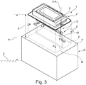
Figure 3 shows a perspective view of the hood ofFigure 2 with the projections of the hood and the control and monitoring unit on a projection plane; -
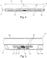
Figure 4 shows a perspective view of the control and monitoring unit of the present invention; -
Figure 5 shows a detail view of the control and monitoring unit ofFigure 4 . - Although this is not expressly shown, the individual features described with reference to each embodiment shall be intended as auxiliary and/or interchangeable with other features, as described with reference to other embodiments.
- A domestic hood of the present invention has been generally designated by numeral 1 in the figures.
- Preferably, the hood 1 of the present invention is a ceiling or pendant hood.
- Particularly, this hood 1 comprises a
housing frame 2, preferably made of metal and possibly having decorative parts made of plastic. - As used herein, the term housing frame is intended to designate a structural element designed to contain hood operating devices (as explained in greater detail below), comprising specially shaped elements and/or covering panels that impart a particular aesthetic appearance to the hood.
- The
housing frame 2 is designed to be secured to a wall, preferably the ceiling, in an area located above a cooktop plane C (seeFigure 3 ). - For instance, the cooktop plane C may be an island plane, as schematically shown in
Figure 3 , or be part of a furnishing element, such as a countertop of a kitchen cabinet. - Particularly, the cooktop plane C includes one or more burners, which may be gas or electric/induction burners (not shown).
- For example, referring to
Figure 3 , the hood 1 is shown to be at a height H from a walkway plane Z, i.e. the indoor floor surface of a building. Generally, the height H at which the hood 1 is disposed is greater than 150 cm and, in the particular embodiment as shown in the annexed figures, is placed for instance at 270 cm from the walkway plane Z. - The cooktop C defines a plane P parallel to the walkway plane Z.
- The
housing frame 2 defines a perimeter or layout whose projection A is visible on the plane P, when the hood 1 is in use. - Particularly, also referring to the particular embodiment of
Figure 3 , the projection A of thehousing frame 2 is found on the plane P, i.e. the cooktop plane C in which food-cooking burners are placed. - In other embodiments, the plane P might not coincide with such top surface, and be at a distance therefrom.
- The
housing frame 2 comprises a first opening 3, and at least one, preferably two,second openings 4, preferably placed on lateral portions of the housing frame (seeFigure 2 ). - The first opening is designed to be engaged by a fume exhaust duct for exhausting cooking fumes outside the house (e.g. through a chimney flue).
- The
second opening 4 is in fluid communication with the environment outside theframe 2 and, in the embodiment ofFigure 2 , within the house, to reintroduce appropriately treated air into the domestic environment, thereby operating in filter mode. - Alternately, the
second embodiment 4 is in fluid communication with the environment outside theframe 2 and, through a chimney flue, such second opening 4 exhausts the extracted gases outside the environment in which the hood is installed, thereby operating in extraction mode. - For these purposes, the hood 1 comprises a forced
air extraction unit 5, comprising an intake section (e.g. delimited by a frame wall exposed to an airflow), and a delivery outlet. The forcedventilation unit 5 is, for example, a fan (of axial or centrifugal type), or another electric operating machine that can withdraw air from an extraction area and send it to a delivery outlet. - The intake section is placed in a bottom region of the
frame 2, i.e. a frame region that faces the cooktop when the hood 1 is in operation. - It shall be noted that the first opening 3 is in fluid communication with the intake section of the forced
extraction unit 5, whereas thesecond opening 4 is in fluid communication with the delivery outlet of the forcedair extraction unit 5. - The hood 1 further comprises at least one filter (not shown), which is operably put in fluid communication with the intake section of the forced
ventilation unit 5 and with the environment outside thehousing frame 2. - In other words, the at least one filter is operably placed upstream from the intake section 5a, such that it will face the cooktop (when the hood is in operation).
- In one aspect, the hood 1 comprises a control and
monitoring unit 8, which is configured to be in electric signal communication with theair extraction unit 5. - Particularly, the control and
monitoring unit 8 is configured to control and monitor theair extraction unit 5 and to supervise other features of the hood 1, as more clearly explained below. - It shall be noted that the control and
monitoring unit 8 can at least switch on/off theair extraction unit 5. - In one aspect of the present invention, the hood 1 comprises suspension means 9 extending from the
housing frame 2. - Particularly, the control and
monitoring unit 8 is located outside thehousing frame 2, i.e. is remote from theframe 2, and is mechanically connected thereto by the suspension means 9. - Advantageously, still referring to
Figure 3 , the control andmonitoring unit 8 is in such a spatial position, relative to thehousing frame 2, that its projection B lies on the projection plane P and is particularly contained in the projection A of thehousing frame 2 defined in the same plane P. - As shown in
Figure 3 , the projection B of the control and monitoring unit 8 (as shown by arrows B') on the plane P is contained within and does not extend beyond the projection A of the housing frame 2 (as shown by arrows A'). - With this arrangement of the control and
monitoring unit 8 relative to thehousing frame 2, the control andmonitoring unit 8 will eventually be external to or remote fromhousing frame 2, but still be exposed to the impinging flow of gases extracted by theair extraction unit 5. - Particularly, the gas flow that impinges upon the control and
monitoring unit 8 is the gas flow that will be created in the space volume defined between the cooktop plane C and thehousing frame 2 of the hood 1, when the forcedair extraction unit 5 is on. - In one aspect, the projection B of the control and
monitoring unit 8 and the projection A of thehousing frame 2 are orthogonal projections on the plane P of the perimeters defined by the control andmonitoring unit 8 and by thehousing frame 2 respectively. - In a preferred embodiment, the suspension means 9 will extend from the
housing frame 2 in a predetermined direction of extension X-X. - Here, the plane P is not only parallel to the cooktop plane C, but is also perpendicular to the predetermined direction of extension X-X.
- Particularly, the suspension means 9 will extend to a length L from the
housing frame 2 in the direction X-X, and will be designed for the control andmonitoring unit 8 to be external to and remote from theframe 2. - For example, A feasible length L of the suspension means 9 ranges from 60 cm and 120 cm.
- In this context, the control and
monitoring unit 8 will be placed at the distance S from the cooktop plane C which is equal to:
- Advantageously, this distance S is the best distance for efficient use of the hood 1 by the user, without incurring the aforementioned drawbacks of prior art hoods, because the control and
monitoring unit 8 is easily reached by the user, but thehousing frame 2 of the hood 1 is out of the field-of-view of the user, thereby providing the free-space feeling of ceiling or pendant hoods. - For the control and
monitoring unit 8 to be connected to thehousing frame 2, the hood 1 comprises latching means 10 for latching the suspension means 9 such that theunit 8 may be fixed at the distance S from the cooktop plane C. - Particularly, the latching means 10 will be disposed in the
housing frame 2 and in theunit 8 and preferably in a portion of theunit 8 and in a portion of theframe 2, such portions being in a mutually faced relationship. - According to one embodiment, the latching means 10 comprise a cable, preferably a pair of cables, but also three, four or more cables, which are designed to support the mass of the control and
monitoring unit 8. - It shall be noted that the Figures only show the part of the latching means that is situated on the
units 8, as the one on theframe 2 is hidden to the view by the covering panel that imparts particular aesthetic appearance to the hood 1. - For this purpose, the cable or pair of cables has a diameter ranging from 0.8 mm to 1.6 mm, preferably all 1.2 mm.
- For example, the single cable or the pair of cables may be formed from a metal material such as steel or other materials, provided the aforementioned diameter values will be met.
- If the suspension means 9 are embodied as a pair of cables, such pair is in such a position that the cables will lie parallel to each other in the direction of extension X-X and perpendicular to the cooktop plane C.
- This arrangement of the cables will advantageously provide balanced connection of the control and
monitoring unit 8 to thehousing frame 2, i.e. with no tilt of the control andmonitoring unit 8 relative to the cooktop plane C. - Alternatively, the suspension means 9 are embodied as metal or polymeric rods or tubes and may extend not only along a straight line, like cables, but also along polygonal broken lines, possibly also connected by curvilinear elements or along curvilinear elements.
- Particularly, in this context, the path of suspension means 9 may be also external to the projection A of the
frame 2 defined on the plane P, although the control andmonitoring unit 8 will be preferably arranged for its projection B to fall within the projection A of the frame on the plane P. - In one aspect, also referring to
Figures 4 and 5 , the control andmonitoring unit 8 comprises acontrol interface 15, which comprises at least one transducer for measuringphysical quantities 11 and/or alight source 14. - The
transducer 11 for measuring physical quantities can detect characteristic parameters in the gas flow extracted by the forcedair extraction unit 5 for automatically enabling/disabling the forced air extraction unit. - Particularly, the transducer for measuring
physical quantities 11 is embodied as a sensor for temperature, heat, humidity and/or Volatile Organic Compounds (V.O.C.) and/or a combination thereof. - The
light source 14 has a power value that is equal to that of a light source installed in a T-shaped or vertical hood (i.e. a hood other than a ceiling or pendant hood), which means that the hood of the present invention can advantageously accommodate light sources of lower power than those of the about discussed prior art. - Particularly, the
light source 14 may be implemented with LED lamps or, alternatively, with other types of lamps. - With the control and
monitoring unit 8 being located at an appropriate height S from the cooktop plane C, the presence of thetransducer 11 can actuate automatically, i.e. with no action by a user, the forcedair extraction unit 5, as soon as such transducer detects a value that exceeds a predetermined threshold. - The
control interface 15 on the control andmonitoring unit 8 comprises one or more of the following devices: - a first manually-operated
control member 12 for switching on/off the forced air extraction unit and optionallyspecific switches 12', 12" for increasing/decreasing the extraction speed of theair extraction unit 5 respectively; - a second manually-operated
control member 13 for turning on/off thelight source 14; -
LED indicators 16 showing the operating state of the hood 1 and/or thelight source 14. - Particularly, the first manually-operated
control member 12 can switch on/off the forcedair extraction unit 5 whenever the user believes that gases should be extracted from the room in which the hood 1 is installed. - This
first control member 12 integrates the automatic operation of thetransducer 11 for fully efficient use of the hood 1 by the user. - Still referring to the accompanying figures and particularly to
Figures 4 and 5 , it shall be noted that, in a preferred embodiment, the control andmonitoring unit 8 defines at least onefirst surface 8a and onesecond surface 8b, which are opposite to each other, and when the hood 1 is in operation, thefirst surface 8a faces the cooktop plane C and thesecond surface 8b faces thehousing frame 2, particularly the opening 3 ofsuch frame 2. - In one aspect, the
first surface 8a is designed to accommodate thecontrol interface 15, with thesecond surface 8b housing the latching means. - It shall be noted that the position of the
control interface 15, and particularly thetransducer 11, in thesurface 8a that faces the cooktop plane C will provide a maximized probability for the transducer to detect the physical quantity of interest, while ensuring a greater effectiveness as compared with prior art food installations. - It shall be also noted that since the
first member 12 and/or thesecond member 13 are placed in thesurface 8a, i.e. the surface that directly faces the cooktop plane C, as the user presses the first and/or thesecond members such members 12 and/or 13 is applied upwards. By this arrangement, as the first and/or thesecond members monitoring unit 8 will not, or will minimally be subjected to such pressure and will not swing, and will instead remain still in its position relative to thehousing frame 2. - This advantage is maximized if the
first member 12 and/or thesecond member 13 are formed with "soft touch" mechanisms. - Preferably, the first and
second surfaces lateral surface 8a, which may also be flat. - According to a particular embodiment, as shown in the Figures, the
surfaces monitoring unit 8 as a parallelepiped in which the length L is much greater than the width "1" and the thickness T. - In one aspect, the electric signal communication between the control and
monitoring unit 8 and the air extraction unit 6 comprises a wired communication. - Preferably, such wired communication carries both an electrical power signal for supplying power to the control and
monitoring unit 8 and an electrical data signal, such as a signal comprising the data detected by thetransducer 11. - Alternatively, the electric signal communication between the control and
monitoring unit 8 and the air extraction unit 6 comprises a wired and Radio-Frequency communication. - Preferably, the wired communication carries an electrical power signal for supplying power to the control and
monitoring unit 8 and the Radio-Frequency communication carries an electrical data signal, such as a signal comprising the data detected by thetransducer 11. - It shall be noted that, if Radio.-Frequency communication is implemented, the control and
monitoring unit 8 will comprise a first transceiver device (not shown), with thehousing frame 2 comprising a second transceiver device (not shown). - Such first and second transceiver devices are in signal communication with each other to transmit the data signal, such as a signal comprising the data detected by the
transducer 11, with a Bluetooth, Zigbee or Radio-Frequency data transmission protocols. - Preferably, the first and second transceiver device are formed as transceivers operating in the 470MHz band, with proprietary protocols such as gate-opening radio controls.
- Those skilled in the art will obviously appreciate that a number of changes and variants may be made to the arrangements as described hereinbefore to meet incidental and specific needs. All of these variants and changes fall within scope of the invention, as defined in the following claims.
Claims (11)
- A domestic hood (1) comprising:- a housing frame (2) defining a perimeter, whose projection (A) falls on a plane (P) parallel to a cooktop plane (C) when said domestic hood is in operation;- a forced air extraction unit (5) housed in said housing frame (2) and comprising at least one gas flow intake section (3);- at least one first opening (3) in said housing frame (2), in fluid communication with the intake section of said forced air extraction unit (5);- a control and monitoring unit (8) having a control interface (15) in electrical signal communication with said air extraction unit (5), and configured to control and monitor said air extraction unit (5);characterized in that it comprises suspension means (9) which extend from said housing frame (2), said control and monitoring unit (8) being located outside said housing frame (2) and being mechanically connected thereto by said suspension means (9), such that a projection (B) of said control and monitoring unit (8) will lie on said plane (P) and fall within said projection (A) of said housing frame (2) on the same plane (P).
- A domestic hood as claimed in claim 1, wherein said suspension means (9) extend from said housing frame (2) in a predetermined direction of extension (X-X), said plane (P) being perpendicular to said predetermined direction of extension (X-X).
- A domestic hood as claimed in claim 1 or 2, wherein said control interface (15) comprises at least one transducer (11) for measuring physical quantities, that can detect characteristic parameters in said gas flow extracted by said forced air extraction unit for automatically enabling/disabling said forced air extraction unit and/or a light source (14).
- A domestic hood as claimed in claim 3, wherein said control interface (15) comprises one or more of the following devices:- a first manually-operated control member (12) for turning on/off the forced air extraction unit;- a second manually-operated control member (13) for turning on/off said light source (14).
- A domestic hood as claimed in any of the preceding claims 2 to 4, wherein said suspension means (9) extend to a preset length (L) from said housing frame (2), said hood (1) comprising latching means (10) for latching said suspension means (9) such that said control and monitoring unit (8) will be external to and remote from said frame.
- A domestic hood as claimed in claims 3 to 5, wherein said control and monitoring unit (8) defines at least one first surface (8a) and one second surface (8b), which are opposite to each other, wherein when said hood (1) is in operation, said first surface (8a) faces said cooktop plane (C) and said second surface (8b) faces said housing frame (2), wherein said first surface accommodates said control interface (15) and said second surface (8b) accommodates said latching means (10).
- A domestic hood as claimed in any of the preceding claims, wherein said electrical signal communication between said control and monitoring unit (8) and said air extraction unit (5) comprises a wired communication, wherein said wired communication carries both an electrical power signal for supplying power to said control and monitoring unit and an electrical data signal.
- A domestic hood as claimed in any of the preceding claims 1 to 6, wherein said electrical signal communication between said control and monitoring unit (8) and said air extraction unit (5) comprises a wired and radio-frequency communication, wherein said wired communication carries an electrical power signal for supplying power to said control and monitoring unit and said radio-frequency communication carries an electrical data signal.
- A domestic hood as claimed in claim 8, wherein said hood (1) comprises a first transceiver device associated with said control and monitoring unit (8) and a second transceiver device associated with said housing frame (2), said first and second transceiver devices being in signal communication with each other to transmit said data signal according to a data transmission protocol, such as Bluetooth, Zigbee or radio-frequency.
- A domestic hood as claimed in any of the preceding claims, wherein said suspension means (9) comprise a pair of cables whose diameter ranges from 0.8 mm to 1.6 mm.
- A domestic hood as claimed in claim 1, wherein:- said air extraction unit (5) comprises a delivery outlet,- said housing frame (2) comprises a second opening (4) in fluid communication with the delivery outlet of said forced air extraction unit and with the environment outside the housing frame,- said first (3) and said second (4) openings being designed to be engaged by a flue exhaust duct,- said hood comprising at least one filter, which is operably placed in fluid communication with the intake section of said forced air extraction unit and with the environment outside said housing frame, for filtering said extracted gas flow.
Priority Applications (1)
| Application Number | Priority Date | Filing Date | Title |
|---|---|---|---|
| PL16204789T PL3214376T3 (en) | 2016-03-03 | 2016-12-16 | Domestic hood with control and monitoring unit |
Applications Claiming Priority (1)
| Application Number | Priority Date | Filing Date | Title |
|---|---|---|---|
| ITUA2016A001328A ITUA20161328A1 (en) | 2016-03-03 | 2016-03-03 | Hood for domestic environments equipped with a command and control unit external to the hood |
Publications (2)
| Publication Number | Publication Date |
|---|---|
| EP3214376A1 true EP3214376A1 (en) | 2017-09-06 |
| EP3214376B1 EP3214376B1 (en) | 2019-10-30 |
Family
ID=56203473
Family Applications (1)
| Application Number | Title | Priority Date | Filing Date |
|---|---|---|---|
| EP16204789.8A Not-in-force EP3214376B1 (en) | 2016-03-03 | 2016-12-16 | Domestic hood with control and monitoring unit |
Country Status (4)
| Country | Link |
|---|---|
| EP (1) | EP3214376B1 (en) |
| ES (1) | ES2757725T3 (en) |
| IT (1) | ITUA20161328A1 (en) |
| PL (1) | PL3214376T3 (en) |
Citations (5)
| Publication number | Priority date | Publication date | Assignee | Title |
|---|---|---|---|---|
| FR2671498A1 (en) * | 1991-01-11 | 1992-07-17 | Dietrich Equip Menager | Suction hood for a work surface |
| DE4142440A1 (en) * | 1991-12-20 | 1993-06-24 | Bosch Siemens Hausgeraete | Fume hood |
| EP2161507A2 (en) * | 2008-09-01 | 2010-03-10 | BSH Bosch und Siemens Hausgeräte GmbH | Vapour extraction device, especially ceiling mounted island hood, and module assembly with such a vapour extraction device |
| EP2327936A1 (en) * | 2009-11-26 | 2011-06-01 | Faber S.p.A. | Hood unit with raising / lowering device |
| EP2775214A1 (en) * | 2013-03-05 | 2014-09-10 | BSH Bosch und Siemens Hausgeräte GmbH | Household appliance with a light source and method for operating a domestic appliance |
Family Cites Families (3)
| Publication number | Priority date | Publication date | Assignee | Title |
|---|---|---|---|---|
| CH678224A5 (en) * | 1989-01-30 | 1991-08-15 | Lufttechnik & Metallbau Ag | Fume hood for kitchen - has fan driven by mains-powered motor controlled by LV switch panel |
| DE29922728U1 (en) * | 1999-12-23 | 2000-03-30 | Bürcher, Friedrich, 82054 Sauerlach | Controllable exhaust ventilation system |
| DE102015200639A1 (en) * | 2015-01-16 | 2016-07-21 | Berbel Ablufttechnik Gmbh | Device for extracting exhaust air |
-
2016
- 2016-03-03 IT ITUA2016A001328A patent/ITUA20161328A1/en unknown
- 2016-12-16 ES ES16204789T patent/ES2757725T3/en active Active
- 2016-12-16 EP EP16204789.8A patent/EP3214376B1/en not_active Not-in-force
- 2016-12-16 PL PL16204789T patent/PL3214376T3/en unknown
Patent Citations (5)
| Publication number | Priority date | Publication date | Assignee | Title |
|---|---|---|---|---|
| FR2671498A1 (en) * | 1991-01-11 | 1992-07-17 | Dietrich Equip Menager | Suction hood for a work surface |
| DE4142440A1 (en) * | 1991-12-20 | 1993-06-24 | Bosch Siemens Hausgeraete | Fume hood |
| EP2161507A2 (en) * | 2008-09-01 | 2010-03-10 | BSH Bosch und Siemens Hausgeräte GmbH | Vapour extraction device, especially ceiling mounted island hood, and module assembly with such a vapour extraction device |
| EP2327936A1 (en) * | 2009-11-26 | 2011-06-01 | Faber S.p.A. | Hood unit with raising / lowering device |
| EP2775214A1 (en) * | 2013-03-05 | 2014-09-10 | BSH Bosch und Siemens Hausgeräte GmbH | Household appliance with a light source and method for operating a domestic appliance |
Also Published As
| Publication number | Publication date |
|---|---|
| ES2757725T3 (en) | 2020-04-30 |
| PL3214376T3 (en) | 2020-03-31 |
| ITUA20161328A1 (en) | 2017-09-03 |
| EP3214376B1 (en) | 2019-10-30 |
Similar Documents
| Publication | Publication Date | Title |
|---|---|---|
| RU2584517C2 (en) | Device, system and method of vent system calibration | |
| US10471482B2 (en) | Exhaust apparatus, system, and method for enhanced capture and containment | |
| ES2922203T3 (en) | Surveillance system and procedure for surveillance and adjustment of air parameters in a space, smoke extractor device for use in a surveillance system | |
| CN101443595B (en) | Controls for ventilation and exhaust ducts and fans | |
| US8511578B2 (en) | Vapor extraction apparatus having an extended range of functions | |
| US20180306449A1 (en) | Combination appliance having a cooktop and steam extraction device | |
| US20070062513A1 (en) | Cooking system with ventilator and blower | |
| US20120083198A1 (en) | Fluid cleaning system and method | |
| JP2013104618A (en) | Indoor circulation type range hood | |
| US20150056911A1 (en) | System for damper activation notification | |
| KR101721541B1 (en) | A hood of gas range | |
| JPH07239988A (en) | Multi-function sensor | |
| JP2008082634A (en) | Range food | |
| JP2008057838A (en) | Range hood and its adjustment method | |
| EP3214376B1 (en) | Domestic hood with control and monitoring unit | |
| US20140283813A1 (en) | Device for extractor hood | |
| JP2016125794A (en) | Exhaust duct device of cooking device hood | |
| US20160131366A1 (en) | Oven range ventilator with microwave compartment | |
| JP2008057839A (en) | Range hood and its adjustment method | |
| KR100666233B1 (en) | Exhaust of the kitchen range hood | |
| AU2014271273B2 (en) | Exhaust apparatus, system, and method for enhanced capture and containment | |
| CA2081822C (en) | Range hood fan with atmospheric humidity sensor | |
| WO2014139537A1 (en) | A kitchen appliance | |
| JP2007192482A (en) | Range food | |
| JPH02184195A (en) | Information management device |
Legal Events
| Date | Code | Title | Description |
|---|---|---|---|
| PUAI | Public reference made under article 153(3) epc to a published international application that has entered the european phase |
Free format text: ORIGINAL CODE: 0009012 |
|
| STAA | Information on the status of an ep patent application or granted ep patent |
Free format text: STATUS: THE APPLICATION HAS BEEN PUBLISHED |
|
| AK | Designated contracting states |
Kind code of ref document: A1 Designated state(s): AL AT BE BG CH CY CZ DE DK EE ES FI FR GB GR HR HU IE IS IT LI LT LU LV MC MK MT NL NO PL PT RO RS SE SI SK SM TR |
|
| AX | Request for extension of the european patent |
Extension state: BA ME |
|
| STAA | Information on the status of an ep patent application or granted ep patent |
Free format text: STATUS: REQUEST FOR EXAMINATION WAS MADE |
|
| 17P | Request for examination filed |
Effective date: 20180222 |
|
| RBV | Designated contracting states (corrected) |
Designated state(s): AL AT BE BG CH CY CZ DE DK EE ES FI FR GB GR HR HU IE IS IT LI LT LU LV MC MK MT NL NO PL PT RO RS SE SI SK SM TR |
|
| STAA | Information on the status of an ep patent application or granted ep patent |
Free format text: STATUS: EXAMINATION IS IN PROGRESS |
|
| 17Q | First examination report despatched |
Effective date: 20181001 |
|
| GRAP | Despatch of communication of intention to grant a patent |
Free format text: ORIGINAL CODE: EPIDOSNIGR1 |
|
| STAA | Information on the status of an ep patent application or granted ep patent |
Free format text: STATUS: GRANT OF PATENT IS INTENDED |
|
| INTG | Intention to grant announced |
Effective date: 20190628 |
|
| GRAS | Grant fee paid |
Free format text: ORIGINAL CODE: EPIDOSNIGR3 |
|
| GRAA | (expected) grant |
Free format text: ORIGINAL CODE: 0009210 |
|
| STAA | Information on the status of an ep patent application or granted ep patent |
Free format text: STATUS: THE PATENT HAS BEEN GRANTED |
|
| AK | Designated contracting states |
Kind code of ref document: B1 Designated state(s): AL AT BE BG CH CY CZ DE DK EE ES FI FR GB GR HR HU IE IS IT LI LT LU LV MC MK MT NL NO PL PT RO RS SE SI SK SM TR |
|
| REG | Reference to a national code |
Ref country code: GB Ref legal event code: FG4D |
|
| REG | Reference to a national code |
Ref country code: CH Ref legal event code: EP |
|
| REG | Reference to a national code |
Ref country code: AT Ref legal event code: REF Ref document number: 1196568 Country of ref document: AT Kind code of ref document: T Effective date: 20191115 |
|
| REG | Reference to a national code |
Ref country code: DE Ref legal event code: R096 Ref document number: 602016023247 Country of ref document: DE |
|
| REG | Reference to a national code |
Ref country code: IE Ref legal event code: FG4D |
|
| REG | Reference to a national code |
Ref country code: LT Ref legal event code: MG4D |
|
| REG | Reference to a national code |
Ref country code: ES Ref legal event code: FG2A Ref document number: 2757725 Country of ref document: ES Kind code of ref document: T3 Effective date: 20200430 |
|
| PG25 | Lapsed in a contracting state [announced via postgrant information from national office to epo] |
Ref country code: GR Free format text: LAPSE BECAUSE OF FAILURE TO SUBMIT A TRANSLATION OF THE DESCRIPTION OR TO PAY THE FEE WITHIN THE PRESCRIBED TIME-LIMIT Effective date: 20200131 Ref country code: NO Free format text: LAPSE BECAUSE OF FAILURE TO SUBMIT A TRANSLATION OF THE DESCRIPTION OR TO PAY THE FEE WITHIN THE PRESCRIBED TIME-LIMIT Effective date: 20200130 Ref country code: NL Free format text: LAPSE BECAUSE OF FAILURE TO SUBMIT A TRANSLATION OF THE DESCRIPTION OR TO PAY THE FEE WITHIN THE PRESCRIBED TIME-LIMIT Effective date: 20191030 Ref country code: LT Free format text: LAPSE BECAUSE OF FAILURE TO SUBMIT A TRANSLATION OF THE DESCRIPTION OR TO PAY THE FEE WITHIN THE PRESCRIBED TIME-LIMIT Effective date: 20191030 Ref country code: PT Free format text: LAPSE BECAUSE OF FAILURE TO SUBMIT A TRANSLATION OF THE DESCRIPTION OR TO PAY THE FEE WITHIN THE PRESCRIBED TIME-LIMIT Effective date: 20200302 Ref country code: LV Free format text: LAPSE BECAUSE OF FAILURE TO SUBMIT A TRANSLATION OF THE DESCRIPTION OR TO PAY THE FEE WITHIN THE PRESCRIBED TIME-LIMIT Effective date: 20191030 Ref country code: SE Free format text: LAPSE BECAUSE OF FAILURE TO SUBMIT A TRANSLATION OF THE DESCRIPTION OR TO PAY THE FEE WITHIN THE PRESCRIBED TIME-LIMIT Effective date: 20191030 Ref country code: BG Free format text: LAPSE BECAUSE OF FAILURE TO SUBMIT A TRANSLATION OF THE DESCRIPTION OR TO PAY THE FEE WITHIN THE PRESCRIBED TIME-LIMIT Effective date: 20200130 Ref country code: FI Free format text: LAPSE BECAUSE OF FAILURE TO SUBMIT A TRANSLATION OF THE DESCRIPTION OR TO PAY THE FEE WITHIN THE PRESCRIBED TIME-LIMIT Effective date: 20191030 |
|
| PGFP | Annual fee paid to national office [announced via postgrant information from national office to epo] |
Ref country code: ES Payment date: 20200121 Year of fee payment: 4 Ref country code: PL Payment date: 20191217 Year of fee payment: 4 |
|
| REG | Reference to a national code |
Ref country code: NL Ref legal event code: MP Effective date: 20191030 |
|
| PG25 | Lapsed in a contracting state [announced via postgrant information from national office to epo] |
Ref country code: IS Free format text: LAPSE BECAUSE OF FAILURE TO SUBMIT A TRANSLATION OF THE DESCRIPTION OR TO PAY THE FEE WITHIN THE PRESCRIBED TIME-LIMIT Effective date: 20200229 Ref country code: RS Free format text: LAPSE BECAUSE OF FAILURE TO SUBMIT A TRANSLATION OF THE DESCRIPTION OR TO PAY THE FEE WITHIN THE PRESCRIBED TIME-LIMIT Effective date: 20191030 Ref country code: HR Free format text: LAPSE BECAUSE OF FAILURE TO SUBMIT A TRANSLATION OF THE DESCRIPTION OR TO PAY THE FEE WITHIN THE PRESCRIBED TIME-LIMIT Effective date: 20191030 |
|
| PG25 | Lapsed in a contracting state [announced via postgrant information from national office to epo] |
Ref country code: AL Free format text: LAPSE BECAUSE OF FAILURE TO SUBMIT A TRANSLATION OF THE DESCRIPTION OR TO PAY THE FEE WITHIN THE PRESCRIBED TIME-LIMIT Effective date: 20191030 |
|
| PG25 | Lapsed in a contracting state [announced via postgrant information from national office to epo] |
Ref country code: DK Free format text: LAPSE BECAUSE OF FAILURE TO SUBMIT A TRANSLATION OF THE DESCRIPTION OR TO PAY THE FEE WITHIN THE PRESCRIBED TIME-LIMIT Effective date: 20191030 Ref country code: EE Free format text: LAPSE BECAUSE OF FAILURE TO SUBMIT A TRANSLATION OF THE DESCRIPTION OR TO PAY THE FEE WITHIN THE PRESCRIBED TIME-LIMIT Effective date: 20191030 Ref country code: CZ Free format text: LAPSE BECAUSE OF FAILURE TO SUBMIT A TRANSLATION OF THE DESCRIPTION OR TO PAY THE FEE WITHIN THE PRESCRIBED TIME-LIMIT Effective date: 20191030 Ref country code: RO Free format text: LAPSE BECAUSE OF FAILURE TO SUBMIT A TRANSLATION OF THE DESCRIPTION OR TO PAY THE FEE WITHIN THE PRESCRIBED TIME-LIMIT Effective date: 20191030 |
|
| REG | Reference to a national code |
Ref country code: CH Ref legal event code: PL Ref country code: DE Ref legal event code: R097 Ref document number: 602016023247 Country of ref document: DE |
|
| REG | Reference to a national code |
Ref country code: AT Ref legal event code: MK05 Ref document number: 1196568 Country of ref document: AT Kind code of ref document: T Effective date: 20191030 |
|
| REG | Reference to a national code |
Ref country code: BE Ref legal event code: MM Effective date: 20191231 |
|
| PG25 | Lapsed in a contracting state [announced via postgrant information from national office to epo] |
Ref country code: SK Free format text: LAPSE BECAUSE OF FAILURE TO SUBMIT A TRANSLATION OF THE DESCRIPTION OR TO PAY THE FEE WITHIN THE PRESCRIBED TIME-LIMIT Effective date: 20191030 Ref country code: MC Free format text: LAPSE BECAUSE OF FAILURE TO SUBMIT A TRANSLATION OF THE DESCRIPTION OR TO PAY THE FEE WITHIN THE PRESCRIBED TIME-LIMIT Effective date: 20191030 Ref country code: SM Free format text: LAPSE BECAUSE OF FAILURE TO SUBMIT A TRANSLATION OF THE DESCRIPTION OR TO PAY THE FEE WITHIN THE PRESCRIBED TIME-LIMIT Effective date: 20191030 |
|
| PLBE | No opposition filed within time limit |
Free format text: ORIGINAL CODE: 0009261 |
|
| STAA | Information on the status of an ep patent application or granted ep patent |
Free format text: STATUS: NO OPPOSITION FILED WITHIN TIME LIMIT |
|
| 26N | No opposition filed |
Effective date: 20200731 |
|
| PG25 | Lapsed in a contracting state [announced via postgrant information from national office to epo] |
Ref country code: LU Free format text: LAPSE BECAUSE OF NON-PAYMENT OF DUE FEES Effective date: 20191216 Ref country code: IE Free format text: LAPSE BECAUSE OF NON-PAYMENT OF DUE FEES Effective date: 20191216 |
|
| PG25 | Lapsed in a contracting state [announced via postgrant information from national office to epo] |
Ref country code: BE Free format text: LAPSE BECAUSE OF NON-PAYMENT OF DUE FEES Effective date: 20191231 Ref country code: AT Free format text: LAPSE BECAUSE OF FAILURE TO SUBMIT A TRANSLATION OF THE DESCRIPTION OR TO PAY THE FEE WITHIN THE PRESCRIBED TIME-LIMIT Effective date: 20191030 Ref country code: CH Free format text: LAPSE BECAUSE OF NON-PAYMENT OF DUE FEES Effective date: 20191231 Ref country code: SI Free format text: LAPSE BECAUSE OF FAILURE TO SUBMIT A TRANSLATION OF THE DESCRIPTION OR TO PAY THE FEE WITHIN THE PRESCRIBED TIME-LIMIT Effective date: 20191030 Ref country code: LI Free format text: LAPSE BECAUSE OF NON-PAYMENT OF DUE FEES Effective date: 20191231 |
|
| PGFP | Annual fee paid to national office [announced via postgrant information from national office to epo] |
Ref country code: FR Payment date: 20201223 Year of fee payment: 5 Ref country code: GB Payment date: 20201223 Year of fee payment: 5 |
|
| PG25 | Lapsed in a contracting state [announced via postgrant information from national office to epo] |
Ref country code: CY Free format text: LAPSE BECAUSE OF FAILURE TO SUBMIT A TRANSLATION OF THE DESCRIPTION OR TO PAY THE FEE WITHIN THE PRESCRIBED TIME-LIMIT Effective date: 20191030 |
|
| PG25 | Lapsed in a contracting state [announced via postgrant information from national office to epo] |
Ref country code: MT Free format text: LAPSE BECAUSE OF FAILURE TO SUBMIT A TRANSLATION OF THE DESCRIPTION OR TO PAY THE FEE WITHIN THE PRESCRIBED TIME-LIMIT Effective date: 20191030 Ref country code: HU Free format text: LAPSE BECAUSE OF FAILURE TO SUBMIT A TRANSLATION OF THE DESCRIPTION OR TO PAY THE FEE WITHIN THE PRESCRIBED TIME-LIMIT; INVALID AB INITIO Effective date: 20161216 |
|
| REG | Reference to a national code |
Ref country code: ES Ref legal event code: FD2A Effective date: 20220209 |
|
| PG25 | Lapsed in a contracting state [announced via postgrant information from national office to epo] |
Ref country code: TR Free format text: LAPSE BECAUSE OF FAILURE TO SUBMIT A TRANSLATION OF THE DESCRIPTION OR TO PAY THE FEE WITHIN THE PRESCRIBED TIME-LIMIT Effective date: 20191030 Ref country code: ES Free format text: LAPSE BECAUSE OF NON-PAYMENT OF DUE FEES Effective date: 20201217 |
|
| PG25 | Lapsed in a contracting state [announced via postgrant information from national office to epo] |
Ref country code: MK Free format text: LAPSE BECAUSE OF FAILURE TO SUBMIT A TRANSLATION OF THE DESCRIPTION OR TO PAY THE FEE WITHIN THE PRESCRIBED TIME-LIMIT Effective date: 20191030 |
|
| GBPC | Gb: european patent ceased through non-payment of renewal fee |
Effective date: 20211216 |
|
| PG25 | Lapsed in a contracting state [announced via postgrant information from national office to epo] |
Ref country code: GB Free format text: LAPSE BECAUSE OF NON-PAYMENT OF DUE FEES Effective date: 20211216 |
|
| PG25 | Lapsed in a contracting state [announced via postgrant information from national office to epo] |
Ref country code: FR Free format text: LAPSE BECAUSE OF NON-PAYMENT OF DUE FEES Effective date: 20211231 |
|
| PGFP | Annual fee paid to national office [announced via postgrant information from national office to epo] |
Ref country code: DE Payment date: 20221213 Year of fee payment: 7 |
|
| PG25 | Lapsed in a contracting state [announced via postgrant information from national office to epo] |
Ref country code: PL Free format text: LAPSE BECAUSE OF NON-PAYMENT OF DUE FEES Effective date: 20201216 |
|
| PGFP | Annual fee paid to national office [announced via postgrant information from national office to epo] |
Ref country code: IT Payment date: 20221222 Year of fee payment: 7 |
|
| REG | Reference to a national code |
Ref country code: DE Ref legal event code: R119 Ref document number: 602016023247 Country of ref document: DE |
|
| PG25 | Lapsed in a contracting state [announced via postgrant information from national office to epo] |
Ref country code: DE Free format text: LAPSE BECAUSE OF NON-PAYMENT OF DUE FEES Effective date: 20240702 |
|
| PG25 | Lapsed in a contracting state [announced via postgrant information from national office to epo] |
Ref country code: DE Free format text: LAPSE BECAUSE OF NON-PAYMENT OF DUE FEES Effective date: 20240702 |
|
| PG25 | Lapsed in a contracting state [announced via postgrant information from national office to epo] |
Ref country code: IT Free format text: LAPSE BECAUSE OF NON-PAYMENT OF DUE FEES Effective date: 20231216 |