EP3214374A1 - Axial fuel staging system for a gas turbine combustor - Google Patents
Axial fuel staging system for a gas turbine combustor Download PDFInfo
- Publication number
- EP3214374A1 EP3214374A1 EP17157810.7A EP17157810A EP3214374A1 EP 3214374 A1 EP3214374 A1 EP 3214374A1 EP 17157810 A EP17157810 A EP 17157810A EP 3214374 A1 EP3214374 A1 EP 3214374A1
- Authority
- EP
- European Patent Office
- Prior art keywords
- conduit
- fuel injector
- secondary fuel
- injector
- assembly
- Prior art date
- Legal status (The legal status is an assumption and is not a legal conclusion. Google has not performed a legal analysis and makes no representation as to the accuracy of the status listed.)
- Granted
Links
Images

Classifications
-
- F—MECHANICAL ENGINEERING; LIGHTING; HEATING; WEAPONS; BLASTING
- F23—COMBUSTION APPARATUS; COMBUSTION PROCESSES
- F23R—GENERATING COMBUSTION PRODUCTS OF HIGH PRESSURE OR HIGH VELOCITY, e.g. GAS-TURBINE COMBUSTION CHAMBERS
- F23R3/00—Continuous combustion chambers using liquid or gaseous fuel
- F23R3/28—Continuous combustion chambers using liquid or gaseous fuel characterised by the fuel supply
- F23R3/286—Continuous combustion chambers using liquid or gaseous fuel characterised by the fuel supply having fuel-air premixing devices
-
- F—MECHANICAL ENGINEERING; LIGHTING; HEATING; WEAPONS; BLASTING
- F23—COMBUSTION APPARATUS; COMBUSTION PROCESSES
- F23R—GENERATING COMBUSTION PRODUCTS OF HIGH PRESSURE OR HIGH VELOCITY, e.g. GAS-TURBINE COMBUSTION CHAMBERS
- F23R3/00—Continuous combustion chambers using liquid or gaseous fuel
- F23R3/28—Continuous combustion chambers using liquid or gaseous fuel characterised by the fuel supply
- F23R3/34—Feeding into different combustion zones
- F23R3/346—Feeding into different combustion zones for staged combustion
-
- F—MECHANICAL ENGINEERING; LIGHTING; HEATING; WEAPONS; BLASTING
- F02—COMBUSTION ENGINES; HOT-GAS OR COMBUSTION-PRODUCT ENGINE PLANTS
- F02C—GAS-TURBINE PLANTS; AIR INTAKES FOR JET-PROPULSION PLANTS; CONTROLLING FUEL SUPPLY IN AIR-BREATHING JET-PROPULSION PLANTS
- F02C7/00—Features, components parts, details or accessories, not provided for in, or of interest apart form groups F02C1/00 - F02C6/00; Air intakes for jet-propulsion plants
- F02C7/22—Fuel supply systems
- F02C7/228—Dividing fuel between various burners
-
- F—MECHANICAL ENGINEERING; LIGHTING; HEATING; WEAPONS; BLASTING
- F23—COMBUSTION APPARATUS; COMBUSTION PROCESSES
- F23R—GENERATING COMBUSTION PRODUCTS OF HIGH PRESSURE OR HIGH VELOCITY, e.g. GAS-TURBINE COMBUSTION CHAMBERS
- F23R3/00—Continuous combustion chambers using liquid or gaseous fuel
- F23R3/002—Wall structures
-
- F—MECHANICAL ENGINEERING; LIGHTING; HEATING; WEAPONS; BLASTING
- F23—COMBUSTION APPARATUS; COMBUSTION PROCESSES
- F23R—GENERATING COMBUSTION PRODUCTS OF HIGH PRESSURE OR HIGH VELOCITY, e.g. GAS-TURBINE COMBUSTION CHAMBERS
- F23R3/00—Continuous combustion chambers using liquid or gaseous fuel
- F23R3/28—Continuous combustion chambers using liquid or gaseous fuel characterised by the fuel supply
-
- F—MECHANICAL ENGINEERING; LIGHTING; HEATING; WEAPONS; BLASTING
- F23—COMBUSTION APPARATUS; COMBUSTION PROCESSES
- F23R—GENERATING COMBUSTION PRODUCTS OF HIGH PRESSURE OR HIGH VELOCITY, e.g. GAS-TURBINE COMBUSTION CHAMBERS
- F23R3/00—Continuous combustion chambers using liquid or gaseous fuel
- F23R3/28—Continuous combustion chambers using liquid or gaseous fuel characterised by the fuel supply
- F23R3/283—Attaching or cooling of fuel injecting means including supports for fuel injectors, stems, or lances
-
- F—MECHANICAL ENGINEERING; LIGHTING; HEATING; WEAPONS; BLASTING
- F23—COMBUSTION APPARATUS; COMBUSTION PROCESSES
- F23R—GENERATING COMBUSTION PRODUCTS OF HIGH PRESSURE OR HIGH VELOCITY, e.g. GAS-TURBINE COMBUSTION CHAMBERS
- F23R3/00—Continuous combustion chambers using liquid or gaseous fuel
- F23R3/28—Continuous combustion chambers using liquid or gaseous fuel characterised by the fuel supply
- F23R3/34—Feeding into different combustion zones
-
- F—MECHANICAL ENGINEERING; LIGHTING; HEATING; WEAPONS; BLASTING
- F05—INDEXING SCHEMES RELATING TO ENGINES OR PUMPS IN VARIOUS SUBCLASSES OF CLASSES F01-F04
- F05D—INDEXING SCHEME FOR ASPECTS RELATING TO NON-POSITIVE-DISPLACEMENT MACHINES OR ENGINES, GAS-TURBINES OR JET-PROPULSION PLANTS
- F05D2220/00—Application
- F05D2220/30—Application in turbines
- F05D2220/32—Application in turbines in gas turbines
-
- F—MECHANICAL ENGINEERING; LIGHTING; HEATING; WEAPONS; BLASTING
- F23—COMBUSTION APPARATUS; COMBUSTION PROCESSES
- F23R—GENERATING COMBUSTION PRODUCTS OF HIGH PRESSURE OR HIGH VELOCITY, e.g. GAS-TURBINE COMBUSTION CHAMBERS
- F23R2900/00—Special features of, or arrangements for continuous combustion chambers; Combustion processes therefor
- F23R2900/00005—Preventing fatigue failures or reducing mechanical stress in gas turbine components
Definitions
- the field of this disclosure relates generally to fuel supply conduits and, more particularly, to a fuel supply conduit assembly for an axial fuel staging (AFS) system of a turbine assembly.
- AFS axial fuel staging
- At least some known turbine assemblies include a compressor, a combustor, and a turbine. Gas flows into the compressor and is compressed. Compressed gas is then discharged into the combustor and mixed with fuel, and the resulting mixture is ignited to generate combustion gases. The combustion gases are channeled from the combustor through the turbine, thereby driving the turbine which, in turn, may power an electrical generator coupled to the turbine.
- each combustion can employs a fuel system including a primary fuel injector at a forward end and an axial fuel staging (AFS) system including a secondary fuel injector at an aft end.
- the combustion can has a liner that defines a combustion chamber, and the secondary fuel injector injects a mixture of fuel and compressed gas into the combustion chamber downstream from the primary fuel injector.
- a fuel supply conduit is coupled to the secondary fuel injector for supplying fuel to the secondary fuel injector.
- the fuel supply conduit is positioned on an outer surface of the combustion can, the fuel supply conduit is susceptible to damage or dislocation, for example, during installation or maintenance. Additionally, if the conduit becomes damaged or dislocated, there is a possibility that the conduit may start leaking fuel.
- an axial fuel staging (AFS) system for a combustor includes a secondary fuel injector, an injector housing surrounding the secondary fuel injector, and a conduit assembly in flow communication with the secondary fuel injector.
- the conduit assembly includes a first conduit for conveying fuel to the secondary fuel injector, and a second conduit circumscribing the first conduit such that a channel is defined between the first conduit and the second conduit. The first conduit and the second conduit terminate within the injector housing.
- a combustor in another aspect, includes a sleeve assembly defining a combustion chamber, and a secondary fuel injector coupled to the sleeve assembly such that the secondary fuel injector is in flow communication with the combustion chamber.
- the combustor also includes an injector housing surrounding the secondary fuel injector, and a conduit assembly radially outward of the sleeve assembly and coupled to the secondary fuel injector for supplying fuel to the secondary fuel injector.
- the conduit assembly includes a first conduit for supplying the fuel to the secondary fuel injector, and a second conduit circumscribing the first conduit to define a channel between the first conduit and the second conduit. The first conduit and the second conduit terminate within the injector housing.
- a turbine assembly in another aspect, includes a turbine and a combustor coupled in flow communication with the turbine.
- the combustor includes a sleeve assembly defining a combustion chamber, and a secondary fuel injector coupled to the sleeve assembly such that the secondary fuel injector is in flow communication with the combustion chamber.
- the combustor also includes an injector housing surrounding the secondary fuel injector, and a conduit assembly radially outward of the sleeve assembly and coupled to the secondary fuel injector for supplying fuel to the secondary fuel injector.
- the conduit assembly includes a first conduit for supplying the fuel to the secondary fuel injector, and a second conduit circumscribing the first conduit to define a channel between the first conduit and the second conduit. The first conduit and the second conduit terminate within the injector housing.
- conduit assemblies by way of example and not by way of limitation.
- the description should enable one of ordinary skill in the art to make and use the fuel supply conduit assemblies, and the description describes several embodiments of the fuel supply conduit assemblies, including what is presently believed to be the best modes of making and using the fuel supply conduit assemblies.
- An exemplary conduit assembly is described herein as being coupled within a turbine assembly. However, it is contemplated that the conduit assembly has general application to a broad range of systems in a variety of fields other than turbine assemblies.
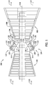
- FIG. 1 illustrates an exemplary turbine assembly 100.
- turbine assembly 100 is a gas turbine assembly that includes a compressor section 102, a combustor section 104, and a turbine section 106 coupled in flow communication with one another within a casing 108.
- the compressor section 102 and the turbine section 106 are joined by a rotor that defines a centerline axis 110.
- a working gas 112 flows into compressor section 102 and is compressed.
- Compressed gas 114 is then channeled into combustor section 104, such that compressed gas 114 is mixed with fuel (not shown) and ignited in combustor section 104 to generate combustion gases 116.
- Combustion gases 116 are channeled through turbine section 106 and then discharged from turbine assembly 100 as exhaust 118.
- combustor section 104 has a plurality of spaced-apart combustion cans 120 and a fuel delivery system coupled to each combustion can 120.
- Each combustion can 120 has a sleeve assembly 124 that includes a liner that defines a combustion chamber 126, and a primary fuel injector 128 is positioned at the forward end of the combustion can 120.
- An axial fuel staging (AFS) system 122 supplies fuel to a secondary fuel injector 130 that is coupled to sleeve assembly 124 downstream from primary fuel injector 128.
- a first mixture 132 of fuel and compressed gas is injected into combustion chamber 126 via primary fuel injector 128, and a second mixture 134 of fuel and compressed gas is injected into combustion chamber 126 via secondary fuel injector 130.
- AFS system 122 also includes a fuel supply conduit assembly 136 for supplying fuel to secondary fuel injector 130, as described below.
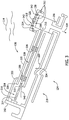
- FIG. 2 illustrates a combustion can 120 having an exemplary AFS system 122.
- AFS system 122 includes a secondary fuel injector 130 that is in flow communication with combustion chamber 126 defined by sleeve assembly 124 of combustion can 120.
- combustion can 120 may be provided with a number of secondary fuel injectors (each with its own AFS system), as needs dictate.
- Such secondary fuel injectors 130 may or may not be uniformly spaced around the circumference of the sleeve assembly 124, and may or may not be located within a single axial plane.
- Combustion chamber 126 has a flow axis 212, such that sleeve assembly 124 has a radial dimension 214 and a circumferential dimension 216 relative to flow axis 212.
- radius refers to a dimension extending outwardly from a center of any suitable shape (e.g., a square, a rectangle, a triangle, etc.) and is not limited to a dimension extending outwardly from a center of a circular shape.
- the term “circumference” refers to a dimension extending around a center of any suitable shape (e.g., a square, a rectangle, a triangle, etc.) and is not limited to a dimension extending around a center of a circular shape.
- sleeve assembly 124 has a liner subassembly 218 and a shell subassembly 220 coupled to liner subassembly 218 such that shell subassembly 220 circumscribes liner subassembly 218 in radially spaced relation to define a cooling duct 222 therebetween.
- subassembly 218 includes a liner component 224 and a transition component 226.
- Liner component 224 has a forward end 228 and an aft end 230, and transition component 226 also has a forward end 232 and an aft end 234.
- Liner component forward end 228 circumscribes primary fuel injector 128, and liner component aft end 230 is coupled to transition component forward end 232.
- Transition component forward end 232 circumscribes liner component aft end 230, and transition component aft end 234 is coupled to a turbine nozzle 236.
- liner subassembly 218 circumscribes combustion chamber 126, which extends from primary fuel injector 128 to turbine nozzle 236.
- liner subassembly 218 may have any suitable number of components coupled between primary fuel injector 128 and turbine nozzle 236 in any suitable manner that permits AFS system 122 to function as described herein (e.g., liner component 224 and transition component 226 may be integrally formed together in some embodiments).
- cooling duct 222 may not be defined between liner subassembly 218 and shell subassembly 220 in some embodiments (i.e., shell subassembly 220 may not be radially spaced apart from liner subassembly 218).
- shell subassembly 220 includes flow sleeve component 238 and a unisleeve component 240.
- Flow sleeve component 238 has a forward end 242 and an aft end 244, and unisleeve component 240 also has a forward end 246 and an aft end 248.
- Flow sleeve component forward end 242 is coupled to a casing flange 250, and flow sleeve component aft end 244 is coupled to unisleeve component forward end 246.
- Unisleeve component forward end 246 circumscribes flow sleeve component aft end 244, and unisleeve component 240 is coupled to transition component 226 of liner subassembly 218 between unisleeve component ends 246 and 248 via a plurality of circumferentially-spaced fasteners (e.g., injector bosses 256), as set forth in more detail below.
- unisleeve component aft end 248 is axially-spaced apart from transition component aft end 234 to define an axial gap 254 therebetween.
- Secondary fuel injector 130 is coupled to unisleeve component 240 of shell subassembly 220 at a boss 256, which penetrates both unisleeve component 240 of shell subassembly 220 and transition component 226 of liner subassembly 218 such that secondary fuel injector 130 extends through unisleeve component 240 and transition component 226 via boss 256.
- boss 256 functions as a fastener for securing unisleeve component 240 to transition component 226.
- secondary fuel injector 130 may be coupled to shell subassembly 220 in any suitable manner, and shell subassembly 220 may have any suitable number of components coupled between casing flange 250 and turbine nozzle 236 in any suitable manner that permits AFS system 122 to function as described herein.
- fuel and compressed gas are supplied to primary fuel injector 128, mixed together, and injected into combustion chamber 126 as a first fuel/air mixture 132.
- fuel is supplied to secondary fuel injector 130 via a fuel supply conduit assembly 136, where fuel is mixed with compressed air in secondary fuel injector 130 and injected into combustion chamber 126 as a second fuel/air mixture 134.
- First fuel/air mixture 132 and second fuel/air mixture 134 are ignited inside combustion chamber 126 to generate a flow of combustion gases 116 that are channeled through turbine nozzle 236.
- FIG. 3 illustrates an exemplary conduit assembly 136 for use in AFS system 122.
- AFS system 122 includes conduit assembly 136, secondary fuel injector 130, and an injector housing 318 that surrounds secondary fuel injector 130.
- Injector housing 318 is coupled to secondary fuel injector 130 and/or sleeve assembly 124 to which secondary fuel injector 130 is mounted, thereby defining a protective environment 324 in which secondary fuel injector 130 is positioned.
- injector housing 318 has at least one attachment site 326 that is substantially aligned with secondary fuel injector 130 and through which a mechanical fastener may be inserted to secure injector housing 318 to secondary fuel injector 130.
- conduit assembly 136 has a first conduit 304 surrounded by a second conduit 320, which acts as a protective sheath.
- the aft end of first conduit 304 is coupled in flow communication with secondary fuel injector 130 for supplying fuel 310 to secondary fuel injector 130.
- the forward end of first conduit 304 is coupled to a casing flange 250 at a flexible joint 314, and first conduit 304 thus extends from joint 314 to secondary fuel injector 130 along a flow axis 316 such that first conduit 304 circumscribes flow axis 316.
- First conduit 304 may have any suitable cross-sectional shape (e.g., first conduit 304 may have a round cross-section in some embodiments, or a square cross-section in other embodiments).
- first conduit 304 may be coupled to, or extend through, an alternate flange or connection point in other embodiments.
- Second conduit 320 may be described as a sheath segment. Second conduit 320 protects first conduit 304 from damage or dislocation, as may occur during the handling, installation, or maintenance of combustion can 120. Second conduit 320 has an inlet end 328 and a discharge end 330. Inlet end 328 of second conduit 320 is positioned radially inward of a conduit housing 332, which shields flexible joint 314, thereby reducing the likelihood that conduit assembly 136 may be dislocated in the event that conduit assembly 136 is snagged or pulled radially outward from combustion can 120. Conduit housing 332 is attached to, or integral with, casing flange 250. Discharge end 330 of second conduit 320 is coupled to, or contained within, injector housing 318.
- Second conduit 320 is radially spaced apart from sleeve assembly 124 in its extension from conduit housing 332 to injector housing 318 to define a lengthwise space 334 between second conduit 320 and sleeve assembly 124.
- first conduit 304 and/or second conduit 320 may be coupled to casing flange 250 and/or sleeve assembly 124 in any suitable manner (e.g., joint 314 may not be flexible in some embodiments, and/or space 334 may not be defined between second conduit 320 and sleeve assembly 124 in some embodiments).
- first conduit 304 extends through second conduit 320 to injector housing 318. More specifically, second conduit 320 circumscribes first conduit 304 about flow axis 316 and is spaced apart from first conduit 304 by at least one spacer 336 (e.g., a gas-permeable spacer such as a mesh spacer) that circumscribes first conduit 304 about flow axis 316 to define a circumferential channel 338 about first conduit 304.
- first conduit 304 may be supported substantially concentrically within second conduit 320 by spacer(s) 336 such that channel 338 circumscribes first conduit 304.
- Spacer 336 may be a mesh screen, which permits air flow therethrough, or may be a spring or wire, which is wrapped around first conduit 304 and permits air flow therearound.
- first conduit 304 may not be supported substantially concentrically within second conduit 320 by spacer(s) 336 (i.e., conduit assembly 136 may not include spacer(s) 336 in some embodiments).
- fuel 310 flows into secondary fuel injector 130 via first conduit 304, and compressed gas 114 flows as a first stream 342 into secondary fuel injector 130 through inlet ports 312 in injector housing 318.
- Compressed gas stream 342 within environment 324 enters secondary fuel injector 130, where the compressed gas stream 342 is mixed with fuel 310 from first conduit 304 prior to being injected as a mixture 134 into combustion chamber 126 defined by sleeve assembly 124.
- a second, relatively small stream 340 of compressed gas 114 flows into environment 324 via second conduit 320 that surrounds first conduit 304 (i.e., second stream 340 flows through inlet end 328, along channel 338, across spacer(s) 336, and into environment 324).
- second conduit 320 functions as a passive purge system in the event that fuel 310 leaks from first conduit 304. Particularly, if fuel 310 leaks from first conduit 304, the leaking fuel 310 is contained within second conduit 320 and is ultimately flushed (or purged) into secondary fuel injector 130 via second stream 340 of compressed gas 114 flowing through channel 338.
- second conduit 320 of conduit assembly 136 may be perforated with a plurality of apertures (not shown) that enable at least one additional stream (not shown) of compressed gas 114 to enter channel 338 for flushing potential fuel leaks into secondary fuel injector 130. Because second conduit 320 of conduit assembly 136 circumscribes first conduit 304 between conduit housing 332 and injector housing 318 along flow axis 316, second conduit 320 shields first conduit 304 from contacting nearby structures (e.g., sleeve assembly 124) or from being contacted itself during installation or maintenance, thereby reducing the likelihood of first conduit 304 being damaged (e.g., bent or dislocated).
- nearby structures e.g., sleeve assembly 124
- the methods and systems described herein provide a circumferential sheath for protecting a fuel conduit in an AFS system of a combustor. Moreover, the methods and systems provide a sheath that completely circumscribes a fuel conduit to facilitate shielding the fuel conduit from damage or dislocation when the combustor is assembled, serviced, and/or operated. Moreover, the methods and systems facilitate containing fuel that may leak from the fuel conduit, and flushing (or purging) the fuel leak(s) into a secondary fuel injector of the AFS system.
- the methods and systems facilitate utilizing less of the overall supply of compressed gas to the secondary fuel injector for the purpose of flushing fuel leaks from the fuel conduit, which enables more compressed gas to enter the secondary fuel injector through a conditioner (or filter) that smooths the flow of compressed gas into the secondary fuel injector. Therefore, the methods and systems enable the AFS system to operate more effectively.
Landscapes
- Engineering & Computer Science (AREA)
- Chemical & Material Sciences (AREA)
- Combustion & Propulsion (AREA)
- Mechanical Engineering (AREA)
- General Engineering & Computer Science (AREA)
- Fuel-Injection Apparatus (AREA)
Abstract
Description
- The field of this disclosure relates generally to fuel supply conduits and, more particularly, to a fuel supply conduit assembly for an axial fuel staging (AFS) system of a turbine assembly.
- At least some known turbine assemblies include a compressor, a combustor, and a turbine. Gas flows into the compressor and is compressed. Compressed gas is then discharged into the combustor and mixed with fuel, and the resulting mixture is ignited to generate combustion gases. The combustion gases are channeled from the combustor through the turbine, thereby driving the turbine which, in turn, may power an electrical generator coupled to the turbine.
- Many known combustors have a plurality of combustion cans, in which each combustion can employs a fuel system including a primary fuel injector at a forward end and an axial fuel staging (AFS) system including a secondary fuel injector at an aft end. The combustion can has a liner that defines a combustion chamber, and the secondary fuel injector injects a mixture of fuel and compressed gas into the combustion chamber downstream from the primary fuel injector. A fuel supply conduit is coupled to the secondary fuel injector for supplying fuel to the secondary fuel injector. However, because the fuel supply conduit is positioned on an outer surface of the combustion can, the fuel supply conduit is susceptible to damage or dislocation, for example, during installation or maintenance. Additionally, if the conduit becomes damaged or dislocated, there is a possibility that the conduit may start leaking fuel.
- In one aspect, an axial fuel staging (AFS) system for a combustor is provided. The AFS system includes a secondary fuel injector, an injector housing surrounding the secondary fuel injector, and a conduit assembly in flow communication with the secondary fuel injector. The conduit assembly includes a first conduit for conveying fuel to the secondary fuel injector, and a second conduit circumscribing the first conduit such that a channel is defined between the first conduit and the second conduit. The first conduit and the second conduit terminate within the injector housing.
- In another aspect, a combustor is provided. The combustor includes a sleeve assembly defining a combustion chamber, and a secondary fuel injector coupled to the sleeve assembly such that the secondary fuel injector is in flow communication with the combustion chamber. The combustor also includes an injector housing surrounding the secondary fuel injector, and a conduit assembly radially outward of the sleeve assembly and coupled to the secondary fuel injector for supplying fuel to the secondary fuel injector. The conduit assembly includes a first conduit for supplying the fuel to the secondary fuel injector, and a second conduit circumscribing the first conduit to define a channel between the first conduit and the second conduit. The first conduit and the second conduit terminate within the injector housing.
- In another aspect, a turbine assembly is provided. The turbine assembly includes a turbine and a combustor coupled in flow communication with the turbine. The combustor includes a sleeve assembly defining a combustion chamber, and a secondary fuel injector coupled to the sleeve assembly such that the secondary fuel injector is in flow communication with the combustion chamber. The combustor also includes an injector housing surrounding the secondary fuel injector, and a conduit assembly radially outward of the sleeve assembly and coupled to the secondary fuel injector for supplying fuel to the secondary fuel injector. The conduit assembly includes a first conduit for supplying the fuel to the secondary fuel injector, and a second conduit circumscribing the first conduit to define a channel between the first conduit and the second conduit. The first conduit and the second conduit terminate within the injector housing.
-
-
Figure 1 is a schematic illustration of an exemplary turbine assembly; -
Figure 2 is a schematic illustration of an exemplary AFS system for use with a combustor of the turbine assembly shown inFigure 1 ; and -
Figure 3 is a schematic illustration of an exemplary conduit assembly for use with the AFS system shown inFigure 2 . - The following detailed description illustrates conduit assemblies by way of example and not by way of limitation. The description should enable one of ordinary skill in the art to make and use the fuel supply conduit assemblies, and the description describes several embodiments of the fuel supply conduit assemblies, including what is presently believed to be the best modes of making and using the fuel supply conduit assemblies. An exemplary conduit assembly is described herein as being coupled within a turbine assembly. However, it is contemplated that the conduit assembly has general application to a broad range of systems in a variety of fields other than turbine assemblies.
-
Figure 1 illustrates anexemplary turbine assembly 100. In the exemplary embodiment,turbine assembly 100 is a gas turbine assembly that includes acompressor section 102, acombustor section 104, and aturbine section 106 coupled in flow communication with one another within acasing 108. Thecompressor section 102 and theturbine section 106 are joined by a rotor that defines acenterline axis 110. In operation, a workinggas 112 flows intocompressor section 102 and is compressed. Compressedgas 114 is then channeled intocombustor section 104, such that compressedgas 114 is mixed with fuel (not shown) and ignited incombustor section 104 to generatecombustion gases 116.Combustion gases 116 are channeled throughturbine section 106 and then discharged fromturbine assembly 100 asexhaust 118. - In the exemplary embodiment,
combustor section 104 has a plurality of spaced-apart combustion cans 120 and a fuel delivery system coupled to each combustion can 120. Each combustion can 120 has asleeve assembly 124 that includes a liner that defines acombustion chamber 126, and aprimary fuel injector 128 is positioned at the forward end of the combustion can 120. An axial fuel staging (AFS)system 122 supplies fuel to asecondary fuel injector 130 that is coupled tosleeve assembly 124 downstream fromprimary fuel injector 128. Afirst mixture 132 of fuel and compressed gas is injected intocombustion chamber 126 viaprimary fuel injector 128, and asecond mixture 134 of fuel and compressed gas is injected intocombustion chamber 126 viasecondary fuel injector 130. Notably, AFSsystem 122 also includes a fuelsupply conduit assembly 136 for supplying fuel tosecondary fuel injector 130, as described below. -
Figure 2 illustrates a combustion can 120 having anexemplary AFS system 122. In the exemplary embodiment,AFS system 122 includes asecondary fuel injector 130 that is in flow communication withcombustion chamber 126 defined bysleeve assembly 124 of combustion can 120. It should be appreciated that, while reference is made herein to a single and exemplary secondary fuel injector and its accompanying AFS system, combustion can 120 may be provided with a number of secondary fuel injectors (each with its own AFS system), as needs dictate. Suchsecondary fuel injectors 130 may or may not be uniformly spaced around the circumference of thesleeve assembly 124, and may or may not be located within a single axial plane. -
Combustion chamber 126 has aflow axis 212, such thatsleeve assembly 124 has aradial dimension 214 and acircumferential dimension 216 relative toflow axis 212. As used herein, the term "radius" (or any variation thereof) refers to a dimension extending outwardly from a center of any suitable shape (e.g., a square, a rectangle, a triangle, etc.) and is not limited to a dimension extending outwardly from a center of a circular shape. Similarly, as used herein, the term "circumference" (or any variation thereof) refers to a dimension extending around a center of any suitable shape (e.g., a square, a rectangle, a triangle, etc.) and is not limited to a dimension extending around a center of a circular shape. - In the exemplary embodiment,
sleeve assembly 124 has aliner subassembly 218 and ashell subassembly 220 coupled toliner subassembly 218 such that shell subassembly 220circumscribes liner subassembly 218 in radially spaced relation to define acooling duct 222 therebetween. In the illustrated embodiment,subassembly 218 includes aliner component 224 and a transition component 226.Liner component 224 has aforward end 228 and anaft end 230, and transition component 226 also has aforward end 232 and anaft end 234. Liner componentforward end 228 circumscribesprimary fuel injector 128, and linercomponent aft end 230 is coupled to transition component forwardend 232. Transition componentforward end 232 circumscribes linercomponent aft end 230, and transitioncomponent aft end 234 is coupled to aturbine nozzle 236. As such,liner subassembly 218circumscribes combustion chamber 126, which extends fromprimary fuel injector 128 toturbine nozzle 236. In other embodiments,liner subassembly 218 may have any suitable number of components coupled betweenprimary fuel injector 128 andturbine nozzle 236 in any suitable manner that permitsAFS system 122 to function as described herein (e.g.,liner component 224 and transition component 226 may be integrally formed together in some embodiments). Alternatively,cooling duct 222 may not be defined betweenliner subassembly 218 andshell subassembly 220 in some embodiments (i.e.,shell subassembly 220 may not be radially spaced apart from liner subassembly 218). - In the exemplary embodiment,
shell subassembly 220 includesflow sleeve component 238 and aunisleeve component 240.Flow sleeve component 238 has aforward end 242 and anaft end 244, andunisleeve component 240 also has a forward end 246 and anaft end 248. Flow sleeve component forwardend 242 is coupled to acasing flange 250, and flow sleevecomponent aft end 244 is coupled to unisleeve component forward end 246. Unisleeve component forward end 246 circumscribes flow sleeve componentaft end 244, andunisleeve component 240 is coupled to transition component 226 ofliner subassembly 218 between unisleeve component ends 246 and 248 via a plurality of circumferentially-spaced fasteners (e.g., injector bosses 256), as set forth in more detail below. As such, unisleeve componentaft end 248 is axially-spaced apart from transition componentaft end 234 to define anaxial gap 254 therebetween. -
Secondary fuel injector 130 is coupled tounisleeve component 240 ofshell subassembly 220 at aboss 256, which penetrates bothunisleeve component 240 ofshell subassembly 220 and transition component 226 ofliner subassembly 218 such thatsecondary fuel injector 130 extends throughunisleeve component 240 and transition component 226 viaboss 256. In one embodiment,boss 256 functions as a fastener for securingunisleeve component 240 to transition component 226. In other embodiments,secondary fuel injector 130 may be coupled toshell subassembly 220 in any suitable manner, andshell subassembly 220 may have any suitable number of components coupled betweencasing flange 250 andturbine nozzle 236 in any suitable manner that permitsAFS system 122 to function as described herein. - During operation of combustion can 120, fuel and compressed gas are supplied to
primary fuel injector 128, mixed together, and injected intocombustion chamber 126 as a first fuel/air mixture 132. Similarly, fuel is supplied tosecondary fuel injector 130 via a fuelsupply conduit assembly 136, where fuel is mixed with compressed air insecondary fuel injector 130 and injected intocombustion chamber 126 as a second fuel/air mixture 134. First fuel/air mixture 132 and second fuel/air mixture 134 are ignited insidecombustion chamber 126 to generate a flow ofcombustion gases 116 that are channeled throughturbine nozzle 236. Becauseliner subassembly 218 experiences higher-temperature operating conditions as a result of circumscribingcombustion chamber 126 in direct contact withcombustion gases 116, a flow of coolinggas 266 is simultaneously channeled through coolingduct 222 viagap 254 to convectively remove heat fromliner subassembly 218 and, therefore, increase the useful life ofsleeve assembly 124. -
Figure 3 illustrates anexemplary conduit assembly 136 for use inAFS system 122. In the exemplary embodiment,AFS system 122 includesconduit assembly 136,secondary fuel injector 130, and aninjector housing 318 that surroundssecondary fuel injector 130.Injector housing 318 is coupled tosecondary fuel injector 130 and/orsleeve assembly 124 to whichsecondary fuel injector 130 is mounted, thereby defining aprotective environment 324 in whichsecondary fuel injector 130 is positioned. Moreover,injector housing 318 has at least oneattachment site 326 that is substantially aligned withsecondary fuel injector 130 and through which a mechanical fastener may be inserted to secureinjector housing 318 tosecondary fuel injector 130. - In the exemplary embodiment,
conduit assembly 136 has afirst conduit 304 surrounded by asecond conduit 320, which acts as a protective sheath. The aft end offirst conduit 304 is coupled in flow communication withsecondary fuel injector 130 for supplyingfuel 310 tosecondary fuel injector 130. The forward end offirst conduit 304 is coupled to acasing flange 250 at a flexible joint 314, andfirst conduit 304 thus extends from joint 314 tosecondary fuel injector 130 along aflow axis 316 such thatfirst conduit 304 circumscribesflow axis 316.First conduit 304 may have any suitable cross-sectional shape (e.g.,first conduit 304 may have a round cross-section in some embodiments, or a square cross-section in other embodiments). Alternatively, althoughfirst conduit 304 extends throughcasing flange 250 in the exemplary embodiment,first conduit 304 may be coupled to, or extend through, an alternate flange or connection point in other embodiments. -
Second conduit 320 may be described as a sheath segment.Second conduit 320 protectsfirst conduit 304 from damage or dislocation, as may occur during the handling, installation, or maintenance of combustion can 120.Second conduit 320 has aninlet end 328 and adischarge end 330.Inlet end 328 ofsecond conduit 320 is positioned radially inward of aconduit housing 332, which shields flexible joint 314, thereby reducing the likelihood thatconduit assembly 136 may be dislocated in the event thatconduit assembly 136 is snagged or pulled radially outward from combustion can 120.Conduit housing 332 is attached to, or integral with,casing flange 250.Discharge end 330 ofsecond conduit 320 is coupled to, or contained within,injector housing 318.Second conduit 320 is radially spaced apart fromsleeve assembly 124 in its extension fromconduit housing 332 toinjector housing 318 to define alengthwise space 334 betweensecond conduit 320 andsleeve assembly 124. In other embodiments,first conduit 304 and/orsecond conduit 320 may be coupled tocasing flange 250 and/orsleeve assembly 124 in any suitable manner (e.g., joint 314 may not be flexible in some embodiments, and/orspace 334 may not be defined betweensecond conduit 320 andsleeve assembly 124 in some embodiments). - Notably,
first conduit 304 extends throughsecond conduit 320 toinjector housing 318. More specifically,second conduit 320 circumscribesfirst conduit 304 aboutflow axis 316 and is spaced apart fromfirst conduit 304 by at least one spacer 336 (e.g., a gas-permeable spacer such as a mesh spacer) that circumscribesfirst conduit 304 aboutflow axis 316 to define acircumferential channel 338 aboutfirst conduit 304. For example,first conduit 304 may be supported substantially concentrically withinsecond conduit 320 by spacer(s) 336 such thatchannel 338 circumscribesfirst conduit 304.Spacer 336 may be a mesh screen, which permits air flow therethrough, or may be a spring or wire, which is wrapped aroundfirst conduit 304 and permits air flow therearound. In other embodiments,first conduit 304 may not be supported substantially concentrically withinsecond conduit 320 by spacer(s) 336 (i.e.,conduit assembly 136 may not include spacer(s) 336 in some embodiments). - During operation,
fuel 310 flows intosecondary fuel injector 130 viafirst conduit 304, andcompressed gas 114 flows as afirst stream 342 intosecondary fuel injector 130 throughinlet ports 312 ininjector housing 318.Compressed gas stream 342 withinenvironment 324 enterssecondary fuel injector 130, where thecompressed gas stream 342 is mixed withfuel 310 fromfirst conduit 304 prior to being injected as amixture 134 intocombustion chamber 126 defined bysleeve assembly 124. Additionally, a second, relativelysmall stream 340 of compressed gas 114 (relatively small in comparison to the volume of firstcompressed gas stream 342 flowing through injector housing 318) flows intoenvironment 324 viasecond conduit 320 that surrounds first conduit 304 (i.e.,second stream 340 flows throughinlet end 328, alongchannel 338, across spacer(s) 336, and into environment 324). Thus,second conduit 320 functions as a passive purge system in the event that fuel 310 leaks fromfirst conduit 304. Particularly, iffuel 310 leaks fromfirst conduit 304, the leakingfuel 310 is contained withinsecond conduit 320 and is ultimately flushed (or purged) intosecondary fuel injector 130 viasecond stream 340 ofcompressed gas 114 flowing throughchannel 338. Additionally, because the majority of thecompressed gas 114 needed by thesecondary fuel injector 130 is supplied byfirst stream 342 via inlet port(s) 312 ofinjector housing 318, only a fraction of the overall supply ofcompressed gas 114 is utilized for the purpose of flushing (or purging)fuel 310 that may leak fromfirst conduit 304. As a result, a large part of the overall flow ofcompressed gas 114 intosecondary fuel injector 130 ends up being conditioned (or filtered) byinjector housing 318, thereby making the overall flow ofcompressed gas 114 intosecondary fuel injector 130 smoother (or more uniform). Optionally, in some embodiments,second conduit 320 ofconduit assembly 136 may be perforated with a plurality of apertures (not shown) that enable at least one additional stream (not shown) of compressedgas 114 to enterchannel 338 for flushing potential fuel leaks intosecondary fuel injector 130. Becausesecond conduit 320 ofconduit assembly 136 circumscribesfirst conduit 304 betweenconduit housing 332 andinjector housing 318 alongflow axis 316,second conduit 320 shieldsfirst conduit 304 from contacting nearby structures (e.g., sleeve assembly 124) or from being contacted itself during installation or maintenance, thereby reducing the likelihood offirst conduit 304 being damaged (e.g., bent or dislocated). - The methods and systems described herein provide a circumferential sheath for protecting a fuel conduit in an AFS system of a combustor. Moreover, the methods and systems provide a sheath that completely circumscribes a fuel conduit to facilitate shielding the fuel conduit from damage or dislocation when the combustor is assembled, serviced, and/or operated. Moreover, the methods and systems facilitate containing fuel that may leak from the fuel conduit, and flushing (or purging) the fuel leak(s) into a secondary fuel injector of the AFS system. Additionally, the methods and systems facilitate utilizing less of the overall supply of compressed gas to the secondary fuel injector for the purpose of flushing fuel leaks from the fuel conduit, which enables more compressed gas to enter the secondary fuel injector through a conditioner (or filter) that smooths the flow of compressed gas into the secondary fuel injector. Therefore, the methods and systems enable the AFS system to operate more effectively.
- Exemplary embodiments of methods and systems are described above in detail. The methods and systems described herein are not limited to the specific embodiments described herein, but rather, components of the methods and systems may be utilized independently and separately from other components described herein. For example, the methods and systems described herein may have other applications not limited to practice with turbine assemblies, as described herein. Rather, the methods and systems described herein can be implemented and utilized in connection with various other industries.
- While the invention has been described in terms of various specific embodiments, those skilled in the art will recognize that the invention can be practiced with modification within the spirit and scope of the claims.
- Various aspects and embodiments of the present invention are defined by the following numbered clauses:
- 1. An axial fuel staging (AFS) system for a combustor, said AFS system comprising:
- a secondary fuel injector;
- an injector housing surrounding said secondary fuel injector; and
- a conduit assembly in flow communication with said secondary fuel injector, wherein said conduit assembly comprises:
- a first conduit for conveying fuel to said secondary fuel injector; and
- a second conduit circumscribing said first conduit such that a channel is defined between said first conduit and said second conduit; and
- wherein said first conduit and said second conduit terminate within said injector housing.
- 2. An AFS system in accordance with clause 1, further comprising a spacer, said spacer being positioned around said first conduit to support said first conduit substantially concentrically within said second conduit.
- 3. An AFS system in accordance with any preceding clause, wherein said spacer is gas-permeable or permits gas to flow therearound.
- 4. An AFS system in accordance with any preceding clause, wherein said injector housing comprises at least one inlet port.
- 5. An AFS system in accordance with any preceding clause, wherein said second conduit comprises an inlet end and a discharge end, said second conduit being coupleable to said injector housing at said discharge end such that said inlet end is in flow communication with said injector housing across said channel and said discharge end.
- 6. An AFS system in accordance with any preceding clause, further comprising a conduit housing, said conduit housing being located radially outward of said inlet end of said second conduit.
- 7. A combustor comprising:
- a sleeve assembly defining a combustion chamber;
- a secondary fuel injector coupled to said sleeve assembly such that said secondary fuel injector is in flow communication with said combustion chamber;
- an injector housing surrounding said secondary fuel injector; and
- a conduit assembly radially outward of said sleeve assembly and coupled to said secondary fuel injector for supplying fuel to said secondary fuel injector, wherein said conduit assembly comprises:
- a first conduit for supplying the fuel to said secondary fuel injector; a second conduit circumscribing said first conduit to define a channel between said first conduit and said second conduit; wherein said first conduit and said second conduit terminate within said injector housing.
- 8. A combustor in accordance with any preceding clause, further comprising a spacer, said spacer being positioned around said first conduit to support said first conduit substantially concentrically within said second conduit.
- 9. A combustor in accordance with any preceding clause, wherein said spacer is gas-permeable or permits gas to flow therearound.
- 10. A combustor in accordance with any preceding clause, wherein said sleeve assembly is coupled to a casing flange, said first conduit extending through said casing flange.
- 11. A combustor in accordance with any preceding clause, wherein said conduit assembly comprises a flexible joint, said first conduit being coupled to said casing flange at said flexible joint.
- 12. A combustor in accordance with any preceding clause, wherein a conduit housing is coupled to said casing flange, such that said conduit housing is positioned radially outward of said flexible joint to shield said flexible joint.
- 13. A combustor in accordance with any preceding clause, wherein said conduit assembly is spaced apart from said sleeve assembly.
- 14. A combustor in accordance with any preceding clause, wherein said second conduit comprises an inlet end and a discharge end, said second conduit being coupled to said injector housing at said discharge end such that said inlet end is in flow communication with said injector housing across said channel and said discharge end.
- 15. A combustor in accordance with any preceding clause, wherein said injector housing comprises at least one inlet port for channeling a first compressed gas stream to the secondary fuel injector; and wherein a second compressed gas stream is directed through said channel from said inlet end to said discharge end of said second conduit.
- 16. A turbine assembly comprising:
- a turbine; and
- a combustor coupled in flow communication with said turbine, wherein said combustor comprises:
- a sleeve assembly defining a combustion chamber;
- a secondary fuel injector coupled to said sleeve assembly such that said secondary fuel injector is in flow communication with said combustion chamber;
- an injector housing surrounding said secondary fuel injector; and
- a conduit assembly radially outward of said sleeve assembly and coupled to said secondary fuel injector for supplying fuel to said secondary fuel injector, wherein said conduit assembly comprises: a first conduit for supplying the fuel to said secondary fuel injector; a second conduit circumscribing said first conduit to define a channel between said first conduit and said second conduit; wherein said first conduit and said second conduit terminate within said injector housing.
- 17. A turbine assembly in accordance with any preceding clause, further comprising a spacer, said spacer being positioned around said first conduit to support said first conduit substantially concentrically within said second conduit.
- 18. A turbine assembly in accordance with any preceding clause, wherein said spacer is gas-permeable or permits gas to flow therearound.
- 19. A turbine assembly in accordance with any preceding clause, wherein said sleeve assembly is coupled to a casing flange, said first conduit extending through said casing flange.
- 20. A turbine assembly in accordance with any preceding clause, wherein said conduit assembly comprises a flexible joint, said first conduit being coupled to said casing flange at said flexible joint.
Claims (10)
- An axial fuel staging (AFS) system (122) for a combustor (104), said AFS system comprising:a secondary fuel injector (130);an injector housing (318) surrounding said secondary fuel injector; anda conduit assembly (136) in flow communication with said secondary fuel injector, wherein said conduit assembly comprises:a first conduit (304) for conveying fuel to said secondary fuel injector; anda second conduit (320) circumscribing said first conduit such that a channel (338) is defined between said first conduit and said second conduit; andwherein said first conduit and said second conduit terminate within said injector housing.
- An AFS system (122) in accordance with claim 1, further comprising a spacer (336), said spacer being positioned around said first conduit (304) to support said first conduit substantially concentrically within said second conduit (320).
- An AFS system (122) in accordance with claim 2, wherein said spacer (336) is gas-permeable or permits gas to flow therearound.
- An AFS system (122) in accordance with claim 1, 2 or 3, wherein said injector housing (318) comprises at least one inlet port (312).
- An AFS system (122) in accordance with any of claims 1 to 4, wherein said second conduit (320) comprises an inlet end (328) and a discharge end (330), said second conduit being coupleable to said injector housing (318) at said discharge end such that said inlet end is in flow communication with said injector housing across said channel (338) and said discharge end.
- An AFS system (122) in accordance with claim 5, further comprising a conduit housing (332), said conduit housing being located radially outward of said inlet end (328) of said second conduit (320).
- A combustor (104) comprising:a sleeve assembly (124) defining a combustion chamber (126);a secondary fuel injector (130) coupled to said sleeve assembly such that said secondary fuel injector is in flow communication with said combustion chamber;an injector housing (318) surrounding said secondary fuel injector; anda conduit assembly (136) radially outward of said sleeve assembly and coupled to said secondary fuel injector for supplying fuel to said secondary fuel injector, wherein said conduit assembly comprises:a first conduit (304) for supplying the fuel to said secondary fuel injector; a second conduit (320) circumscribing said first conduit to define a channel (338) between said first conduit and said second conduit; wherein said first conduit and said second conduit terminate within said injector housing.
- A combustor (104) in accordance with claim 7, further comprising a spacer (336), said spacer being positioned around said first conduit (304) to support said first conduit substantially concentrically within said second conduit (320).
- A combustor (104) in accordance with claim 8, wherein said spacer (336) is gas-permeable or permits gas to flow therearound.
- A combustor (104) in accordance with claim 7, 8 or 9, wherein said sleeve assembly (124) is coupled to a casing flange (250), said first conduit (304) extending through said casing flange.
Applications Claiming Priority (1)
| Application Number | Priority Date | Filing Date | Title |
|---|---|---|---|
| US15/061,434 US10228141B2 (en) | 2016-03-04 | 2016-03-04 | Fuel supply conduit assemblies |
Publications (2)
| Publication Number | Publication Date |
|---|---|
| EP3214374A1 true EP3214374A1 (en) | 2017-09-06 |
| EP3214374B1 EP3214374B1 (en) | 2019-06-05 |
Family
ID=58158976
Family Applications (1)
| Application Number | Title | Priority Date | Filing Date |
|---|---|---|---|
| EP17157810.7A Active EP3214374B1 (en) | 2016-03-04 | 2017-02-24 | Axial fuel staging system for a gas turbine combustor |
Country Status (4)
| Country | Link |
|---|---|
| US (1) | US10228141B2 (en) |
| EP (1) | EP3214374B1 (en) |
| JP (1) | JP7038476B2 (en) |
| CN (1) | CN107152701B (en) |
Cited By (3)
| Publication number | Priority date | Publication date | Assignee | Title |
|---|---|---|---|---|
| EP3495736A1 (en) * | 2017-12-11 | 2019-06-12 | General Electric Company | Axial fuel staging system for gas turbine combustors |
| US11156164B2 (en) | 2019-05-21 | 2021-10-26 | General Electric Company | System and method for high frequency accoustic dampers with caps |
| US11174792B2 (en) | 2019-05-21 | 2021-11-16 | General Electric Company | System and method for high frequency acoustic dampers with baffles |
Families Citing this family (7)
| Publication number | Priority date | Publication date | Assignee | Title |
|---|---|---|---|---|
| US10228141B2 (en) | 2016-03-04 | 2019-03-12 | General Electric Company | Fuel supply conduit assemblies |
| US10203114B2 (en) | 2016-03-04 | 2019-02-12 | General Electric Company | Sleeve assemblies and methods of fabricating same |
| FR3110197B1 (en) * | 2020-05-14 | 2022-12-23 | Ge Energy Products France Snc | REACTIVE GAS FUEL PURGE SYSTEM |
| US12044411B2 (en) * | 2021-06-17 | 2024-07-23 | Ge Infrastructure Technology Llc | Combustor having fuel sweeping structures |
| US11435080B1 (en) * | 2021-06-17 | 2022-09-06 | General Electric Company | Combustor having fuel sweeping structures |
| US11898753B2 (en) * | 2021-10-11 | 2024-02-13 | Ge Infrastructure Technology Llc | System and method for sweeping leaked fuel in gas turbine system |
| CN116906223B (en) * | 2023-06-19 | 2026-03-03 | 西安近代化学研究所 | Stepless throttle passage area adjusting structure and powder fuel supply system |
Citations (2)
| Publication number | Priority date | Publication date | Assignee | Title |
|---|---|---|---|---|
| CH698570A2 (en) * | 2008-02-28 | 2009-08-31 | Gen Electric | Fuel nozzle assembly for combustion chambers. |
| US20140260273A1 (en) * | 2013-03-18 | 2014-09-18 | General Electric Company | Continuous combustion liner for a combustor of a gas turbine |
Family Cites Families (53)
| Publication number | Priority date | Publication date | Assignee | Title |
|---|---|---|---|---|
| US4099799A (en) | 1977-04-28 | 1978-07-11 | Nasa | Cantilever mounted resilient pad gas bearing |
| DE2807119C2 (en) | 1978-02-20 | 1986-04-10 | Fa. A. Raymond, 7850 Lörrach | Cable clamp for variable cable diameters |
| US4567730A (en) | 1983-10-03 | 1986-02-04 | General Electric Company | Shielded combustor |
| US4903480A (en) | 1988-09-16 | 1990-02-27 | General Electric Company | Hypersonic scramjet engine fuel injector |
| US5220787A (en) | 1991-04-29 | 1993-06-22 | Aerojet-General Corporation | Scramjet injector |
| GB2278431A (en) | 1993-05-24 | 1994-11-30 | Rolls Royce Plc | A gas turbine engine combustion chamber |
| GB9410233D0 (en) * | 1994-05-21 | 1994-07-06 | Rolls Royce Plc | A gas turbine engine combustion chamber |
| US5791137A (en) | 1995-11-13 | 1998-08-11 | United Technologies Corporation | Radial inflow dual fuel injector |
| DE29618609U1 (en) | 1996-10-25 | 1996-12-12 | Behla, Karl-Otto, 01561 Ebersbach | Plastic pipe clamp |
| US6915636B2 (en) | 2002-07-15 | 2005-07-12 | Power Systems Mfg., Llc | Dual fuel fin mixer secondary fuel nozzle |
| DE102004045993B4 (en) | 2004-09-22 | 2006-11-16 | Poloplast Gmbh & Co.Kg | pipe clamp |
| US7878000B2 (en) | 2005-12-20 | 2011-02-01 | General Electric Company | Pilot fuel injector for mixer assembly of a high pressure gas turbine engine |
| US7762075B2 (en) | 2007-08-14 | 2010-07-27 | General Electric Company | Combustion liner stop in a gas turbine |
| CA2597846C (en) | 2007-08-16 | 2014-10-14 | General Electric Company | Pilot fuel injector for mixer assembly of a high pressure gas turbine engine |
| FR2926604B1 (en) | 2008-01-23 | 2010-03-26 | Snecma | CENTERING A WORKPIECE WITHIN A ROTOR SHAFT IN A TURBOMACHINE |
| US8113001B2 (en) | 2008-09-30 | 2012-02-14 | General Electric Company | Tubular fuel injector for secondary fuel nozzle |
| US8438856B2 (en) | 2009-03-02 | 2013-05-14 | General Electric Company | Effusion cooled one-piece can combustor |
| US8397511B2 (en) | 2009-05-19 | 2013-03-19 | General Electric Company | System and method for cooling a wall of a gas turbine combustor |
| US8646277B2 (en) | 2010-02-19 | 2014-02-11 | General Electric Company | Combustor liner for a turbine engine with venturi and air deflector |
| US8590311B2 (en) | 2010-04-28 | 2013-11-26 | General Electric Company | Pocketed air and fuel mixing tube |
| US8752386B2 (en) * | 2010-05-25 | 2014-06-17 | Siemens Energy, Inc. | Air/fuel supply system for use in a gas turbine engine |
| US8745987B2 (en) | 2010-10-28 | 2014-06-10 | General Electric Company | Late lean injection manifold |
| US8387391B2 (en) | 2010-12-17 | 2013-03-05 | General Electric Company | Aerodynamically enhanced fuel nozzle |
| US8863525B2 (en) | 2011-01-03 | 2014-10-21 | General Electric Company | Combustor with fuel staggering for flame holding mitigation |
| US20120304652A1 (en) | 2011-05-31 | 2012-12-06 | General Electric Company | Injector apparatus |
| CN103649642B (en) * | 2011-06-30 | 2016-05-04 | 通用电气公司 | Burner and the method for supplying fuel to burner |
| EP2742291B1 (en) | 2011-08-11 | 2020-07-08 | General Electric Company | System for injecting fuel in a gas turbine engine |
| US9303872B2 (en) | 2011-09-15 | 2016-04-05 | General Electric Company | Fuel injector |
| US8869536B2 (en) | 2012-07-26 | 2014-10-28 | General Electric Company | Liner stop for turbine system combustor |
| FR2997997B1 (en) | 2012-11-12 | 2014-12-26 | Snecma | AIR TUBE SUPPORT SUPPORT IN A TURBOMACHINE |
| WO2014090741A1 (en) | 2012-12-14 | 2014-06-19 | Siemens Aktiengesellschaft | Gas turbine comprising at least one tubular combustion chamber |
| US9366438B2 (en) * | 2013-02-14 | 2016-06-14 | Siemens Aktiengesellschaft | Flow sleeve inlet assembly in a gas turbine engine |
| US9316155B2 (en) | 2013-03-18 | 2016-04-19 | General Electric Company | System for providing fuel to a combustor |
| US9316396B2 (en) | 2013-03-18 | 2016-04-19 | General Electric Company | Hot gas path duct for a combustor of a gas turbine |
| US9267436B2 (en) | 2013-03-18 | 2016-02-23 | General Electric Company | Fuel distribution manifold for a combustor of a gas turbine |
| US9376961B2 (en) | 2013-03-18 | 2016-06-28 | General Electric Company | System for controlling a flow rate of a compressed working fluid to a combustor fuel injector |
| US9291350B2 (en) | 2013-03-18 | 2016-03-22 | General Electric Company | System for providing a working fluid to a combustor |
| US9631812B2 (en) | 2013-03-18 | 2017-04-25 | General Electric Company | Support frame and method for assembly of a combustion module of a gas turbine |
| US9360217B2 (en) | 2013-03-18 | 2016-06-07 | General Electric Company | Flow sleeve for a combustion module of a gas turbine |
| US9322556B2 (en) | 2013-03-18 | 2016-04-26 | General Electric Company | Flow sleeve assembly for a combustion module of a gas turbine combustor |
| US10436445B2 (en) | 2013-03-18 | 2019-10-08 | General Electric Company | Assembly for controlling clearance between a liner and stationary nozzle within a gas turbine |
| US20140260318A1 (en) | 2013-03-18 | 2014-09-18 | General Electric Company | Side seal slot for a combustion liner |
| US9400114B2 (en) | 2013-03-18 | 2016-07-26 | General Electric Company | Combustor support assembly for mounting a combustion module of a gas turbine |
| US9989254B2 (en) | 2013-06-03 | 2018-06-05 | General Electric Company | Combustor leakage control system |
| US20150027126A1 (en) * | 2013-07-24 | 2015-01-29 | General Electric Company | System for providing fuel to a combustor |
| US9803864B2 (en) * | 2014-06-24 | 2017-10-31 | General Electric Company | Turbine air flow conditioner |
| US20160265782A1 (en) | 2015-03-10 | 2016-09-15 | General Electric Company | Air shield for a fuel injector of a combustor |
| US20160265781A1 (en) | 2015-03-10 | 2016-09-15 | General Electric Company | Air shield for a fuel injector of a combustor |
| US20170254540A1 (en) | 2016-03-04 | 2017-09-07 | General Electric Company | Spacers and conduit assemblies having the same |
| US10228141B2 (en) | 2016-03-04 | 2019-03-12 | General Electric Company | Fuel supply conduit assemblies |
| US10203114B2 (en) | 2016-03-04 | 2019-02-12 | General Electric Company | Sleeve assemblies and methods of fabricating same |
| US10344978B2 (en) | 2016-03-15 | 2019-07-09 | General Electric Company | Combustion liner cooling |
| US20170268783A1 (en) | 2016-03-15 | 2017-09-21 | General Electric Company | Axially staged fuel injector assembly mounting |
-
2016
- 2016-03-04 US US15/061,434 patent/US10228141B2/en active Active
-
2017
- 2017-02-23 JP JP2017031629A patent/JP7038476B2/en active Active
- 2017-02-24 EP EP17157810.7A patent/EP3214374B1/en active Active
- 2017-03-03 CN CN201710124235.5A patent/CN107152701B/en active Active
Patent Citations (2)
| Publication number | Priority date | Publication date | Assignee | Title |
|---|---|---|---|---|
| CH698570A2 (en) * | 2008-02-28 | 2009-08-31 | Gen Electric | Fuel nozzle assembly for combustion chambers. |
| US20140260273A1 (en) * | 2013-03-18 | 2014-09-18 | General Electric Company | Continuous combustion liner for a combustor of a gas turbine |
Cited By (5)
| Publication number | Priority date | Publication date | Assignee | Title |
|---|---|---|---|---|
| EP3495736A1 (en) * | 2017-12-11 | 2019-06-12 | General Electric Company | Axial fuel staging system for gas turbine combustors |
| CN109899832A (en) * | 2017-12-11 | 2019-06-18 | 通用电气公司 | Axial fuel hierarchy system for gas turbine combustor |
| CN109899832B (en) * | 2017-12-11 | 2023-04-21 | 通用电气公司 | Axial fuel staging system for a gas turbine combustor |
| US11156164B2 (en) | 2019-05-21 | 2021-10-26 | General Electric Company | System and method for high frequency accoustic dampers with caps |
| US11174792B2 (en) | 2019-05-21 | 2021-11-16 | General Electric Company | System and method for high frequency acoustic dampers with baffles |
Also Published As
| Publication number | Publication date |
|---|---|
| JP2017166807A (en) | 2017-09-21 |
| US10228141B2 (en) | 2019-03-12 |
| JP7038476B2 (en) | 2022-03-18 |
| CN107152701A (en) | 2017-09-12 |
| CN107152701B (en) | 2021-02-02 |
| US20170254542A1 (en) | 2017-09-07 |
| EP3214374B1 (en) | 2019-06-05 |
Similar Documents
| Publication | Publication Date | Title |
|---|---|---|
| EP3214374B1 (en) | Axial fuel staging system for a gas turbine combustor | |
| EP3343108B1 (en) | System for dissipating fuel egress in fuel supply conduit assemblies | |
| US8448444B2 (en) | Method and apparatus for mounting transition piece in combustor | |
| CA2603619C (en) | Internal fuel manifold and fuel inlet connection | |
| EP2589875B1 (en) | injection Apparatus | |
| US9784186B2 (en) | Device for mounting a spark plug in a combustion engine of a gas turbine engine | |
| EP3220051A1 (en) | Bundled tube fuel nozzle with vibration damping | |
| CN107975820A (en) | Burner air shade assembly and burner assembly | |
| EP3214372A1 (en) | Spacers and conduit assemblies having the same | |
| CN107152699B (en) | Sleeve assembly and method of making the same | |
| US10634344B2 (en) | Fuel nozzle assembly with fuel purge | |
| EP2045527A2 (en) | Faceted dome assemblies for gas turbine engine combustors | |
| EP3309457A1 (en) | Combustion dynamics mitigation system | |
| EP3586061B1 (en) | Endcover assembly for a combustor | |
| CN104185763B (en) | Gas turbine combustor | |
| EP4105557B1 (en) | Combustor having fuel sweeping structures |
Legal Events
| Date | Code | Title | Description |
|---|---|---|---|
| PUAI | Public reference made under article 153(3) epc to a published international application that has entered the european phase |
Free format text: ORIGINAL CODE: 0009012 |
|
| STAA | Information on the status of an ep patent application or granted ep patent |
Free format text: STATUS: THE APPLICATION HAS BEEN PUBLISHED |
|
| AK | Designated contracting states |
Kind code of ref document: A1 Designated state(s): AL AT BE BG CH CY CZ DE DK EE ES FI FR GB GR HR HU IE IS IT LI LT LU LV MC MK MT NL NO PL PT RO RS SE SI SK SM TR |
|
| AX | Request for extension of the european patent |
Extension state: BA ME |
|
| STAA | Information on the status of an ep patent application or granted ep patent |
Free format text: STATUS: REQUEST FOR EXAMINATION WAS MADE |
|
| 17P | Request for examination filed |
Effective date: 20180306 |
|
| RBV | Designated contracting states (corrected) |
Designated state(s): AL AT BE BG CH CY CZ DE DK EE ES FI FR GB GR HR HU IE IS IT LI LT LU LV MC MK MT NL NO PL PT RO RS SE SI SK SM TR |
|
| GRAP | Despatch of communication of intention to grant a patent |
Free format text: ORIGINAL CODE: EPIDOSNIGR1 |
|
| STAA | Information on the status of an ep patent application or granted ep patent |
Free format text: STATUS: GRANT OF PATENT IS INTENDED |
|
| RIC1 | Information provided on ipc code assigned before grant |
Ipc: F23R 3/28 20060101ALI20190107BHEP Ipc: F23R 3/34 20060101AFI20190107BHEP Ipc: F02C 7/228 20060101ALI20190107BHEP |
|
| INTG | Intention to grant announced |
Effective date: 20190207 |
|
| GRAS | Grant fee paid |
Free format text: ORIGINAL CODE: EPIDOSNIGR3 |
|
| GRAA | (expected) grant |
Free format text: ORIGINAL CODE: 0009210 |
|
| STAA | Information on the status of an ep patent application or granted ep patent |
Free format text: STATUS: THE PATENT HAS BEEN GRANTED |
|
| AK | Designated contracting states |
Kind code of ref document: B1 Designated state(s): AL AT BE BG CH CY CZ DE DK EE ES FI FR GB GR HR HU IE IS IT LI LT LU LV MC MK MT NL NO PL PT RO RS SE SI SK SM TR |
|
| REG | Reference to a national code |
Ref country code: GB Ref legal event code: FG4D |
|
| REG | Reference to a national code |
Ref country code: CH Ref legal event code: EP |
|
| REG | Reference to a national code |
Ref country code: AT Ref legal event code: REF Ref document number: 1140391 Country of ref document: AT Kind code of ref document: T Effective date: 20190615 |
|
| REG | Reference to a national code |
Ref country code: IE Ref legal event code: FG4D |
|
| REG | Reference to a national code |
Ref country code: DE Ref legal event code: R096 Ref document number: 602017004247 Country of ref document: DE |
|
| REG | Reference to a national code |
Ref country code: NL Ref legal event code: MP Effective date: 20190605 |
|
| REG | Reference to a national code |
Ref country code: LT Ref legal event code: MG4D |
|
| PG25 | Lapsed in a contracting state [announced via postgrant information from national office to epo] |
Ref country code: LT Free format text: LAPSE BECAUSE OF FAILURE TO SUBMIT A TRANSLATION OF THE DESCRIPTION OR TO PAY THE FEE WITHIN THE PRESCRIBED TIME-LIMIT Effective date: 20190605 Ref country code: NO Free format text: LAPSE BECAUSE OF FAILURE TO SUBMIT A TRANSLATION OF THE DESCRIPTION OR TO PAY THE FEE WITHIN THE PRESCRIBED TIME-LIMIT Effective date: 20190905 Ref country code: HR Free format text: LAPSE BECAUSE OF FAILURE TO SUBMIT A TRANSLATION OF THE DESCRIPTION OR TO PAY THE FEE WITHIN THE PRESCRIBED TIME-LIMIT Effective date: 20190605 Ref country code: ES Free format text: LAPSE BECAUSE OF FAILURE TO SUBMIT A TRANSLATION OF THE DESCRIPTION OR TO PAY THE FEE WITHIN THE PRESCRIBED TIME-LIMIT Effective date: 20190605 Ref country code: SE Free format text: LAPSE BECAUSE OF FAILURE TO SUBMIT A TRANSLATION OF THE DESCRIPTION OR TO PAY THE FEE WITHIN THE PRESCRIBED TIME-LIMIT Effective date: 20190605 Ref country code: FI Free format text: LAPSE BECAUSE OF FAILURE TO SUBMIT A TRANSLATION OF THE DESCRIPTION OR TO PAY THE FEE WITHIN THE PRESCRIBED TIME-LIMIT Effective date: 20190605 Ref country code: AL Free format text: LAPSE BECAUSE OF FAILURE TO SUBMIT A TRANSLATION OF THE DESCRIPTION OR TO PAY THE FEE WITHIN THE PRESCRIBED TIME-LIMIT Effective date: 20190605 |
|
| PG25 | Lapsed in a contracting state [announced via postgrant information from national office to epo] |
Ref country code: BG Free format text: LAPSE BECAUSE OF FAILURE TO SUBMIT A TRANSLATION OF THE DESCRIPTION OR TO PAY THE FEE WITHIN THE PRESCRIBED TIME-LIMIT Effective date: 20190905 Ref country code: GR Free format text: LAPSE BECAUSE OF FAILURE TO SUBMIT A TRANSLATION OF THE DESCRIPTION OR TO PAY THE FEE WITHIN THE PRESCRIBED TIME-LIMIT Effective date: 20190906 Ref country code: LV Free format text: LAPSE BECAUSE OF FAILURE TO SUBMIT A TRANSLATION OF THE DESCRIPTION OR TO PAY THE FEE WITHIN THE PRESCRIBED TIME-LIMIT Effective date: 20190605 Ref country code: RS Free format text: LAPSE BECAUSE OF FAILURE TO SUBMIT A TRANSLATION OF THE DESCRIPTION OR TO PAY THE FEE WITHIN THE PRESCRIBED TIME-LIMIT Effective date: 20190605 |
|
| REG | Reference to a national code |
Ref country code: AT Ref legal event code: MK05 Ref document number: 1140391 Country of ref document: AT Kind code of ref document: T Effective date: 20190605 |
|
| PG25 | Lapsed in a contracting state [announced via postgrant information from national office to epo] |
Ref country code: RO Free format text: LAPSE BECAUSE OF FAILURE TO SUBMIT A TRANSLATION OF THE DESCRIPTION OR TO PAY THE FEE WITHIN THE PRESCRIBED TIME-LIMIT Effective date: 20190605 Ref country code: SK Free format text: LAPSE BECAUSE OF FAILURE TO SUBMIT A TRANSLATION OF THE DESCRIPTION OR TO PAY THE FEE WITHIN THE PRESCRIBED TIME-LIMIT Effective date: 20190605 Ref country code: CZ Free format text: LAPSE BECAUSE OF FAILURE TO SUBMIT A TRANSLATION OF THE DESCRIPTION OR TO PAY THE FEE WITHIN THE PRESCRIBED TIME-LIMIT Effective date: 20190605 Ref country code: NL Free format text: LAPSE BECAUSE OF FAILURE TO SUBMIT A TRANSLATION OF THE DESCRIPTION OR TO PAY THE FEE WITHIN THE PRESCRIBED TIME-LIMIT Effective date: 20190605 Ref country code: PT Free format text: LAPSE BECAUSE OF FAILURE TO SUBMIT A TRANSLATION OF THE DESCRIPTION OR TO PAY THE FEE WITHIN THE PRESCRIBED TIME-LIMIT Effective date: 20191007 Ref country code: AT Free format text: LAPSE BECAUSE OF FAILURE TO SUBMIT A TRANSLATION OF THE DESCRIPTION OR TO PAY THE FEE WITHIN THE PRESCRIBED TIME-LIMIT Effective date: 20190605 Ref country code: EE Free format text: LAPSE BECAUSE OF FAILURE TO SUBMIT A TRANSLATION OF THE DESCRIPTION OR TO PAY THE FEE WITHIN THE PRESCRIBED TIME-LIMIT Effective date: 20190605 |
|
| PG25 | Lapsed in a contracting state [announced via postgrant information from national office to epo] |
Ref country code: IS Free format text: LAPSE BECAUSE OF FAILURE TO SUBMIT A TRANSLATION OF THE DESCRIPTION OR TO PAY THE FEE WITHIN THE PRESCRIBED TIME-LIMIT Effective date: 20191005 Ref country code: SM Free format text: LAPSE BECAUSE OF FAILURE TO SUBMIT A TRANSLATION OF THE DESCRIPTION OR TO PAY THE FEE WITHIN THE PRESCRIBED TIME-LIMIT Effective date: 20190605 |
|
| REG | Reference to a national code |
Ref country code: DE Ref legal event code: R097 Ref document number: 602017004247 Country of ref document: DE |
|
| PG25 | Lapsed in a contracting state [announced via postgrant information from national office to epo] |
Ref country code: TR Free format text: LAPSE BECAUSE OF FAILURE TO SUBMIT A TRANSLATION OF THE DESCRIPTION OR TO PAY THE FEE WITHIN THE PRESCRIBED TIME-LIMIT Effective date: 20190605 |
|
| PLBE | No opposition filed within time limit |
Free format text: ORIGINAL CODE: 0009261 |
|
| STAA | Information on the status of an ep patent application or granted ep patent |
Free format text: STATUS: NO OPPOSITION FILED WITHIN TIME LIMIT |
|
| PG25 | Lapsed in a contracting state [announced via postgrant information from national office to epo] |
Ref country code: PL Free format text: LAPSE BECAUSE OF FAILURE TO SUBMIT A TRANSLATION OF THE DESCRIPTION OR TO PAY THE FEE WITHIN THE PRESCRIBED TIME-LIMIT Effective date: 20190605 Ref country code: DK Free format text: LAPSE BECAUSE OF FAILURE TO SUBMIT A TRANSLATION OF THE DESCRIPTION OR TO PAY THE FEE WITHIN THE PRESCRIBED TIME-LIMIT Effective date: 20190605 |
|
| 26N | No opposition filed |
Effective date: 20200306 |
|
| PG25 | Lapsed in a contracting state [announced via postgrant information from national office to epo] |
Ref country code: SI Free format text: LAPSE BECAUSE OF FAILURE TO SUBMIT A TRANSLATION OF THE DESCRIPTION OR TO PAY THE FEE WITHIN THE PRESCRIBED TIME-LIMIT Effective date: 20190605 |
|
| REG | Reference to a national code |
Ref country code: CH Ref legal event code: PL |
|
| REG | Reference to a national code |
Ref country code: BE Ref legal event code: MM Effective date: 20200229 |
|
| PG25 | Lapsed in a contracting state [announced via postgrant information from national office to epo] |
Ref country code: LU Free format text: LAPSE BECAUSE OF NON-PAYMENT OF DUE FEES Effective date: 20200224 Ref country code: MC Free format text: LAPSE BECAUSE OF FAILURE TO SUBMIT A TRANSLATION OF THE DESCRIPTION OR TO PAY THE FEE WITHIN THE PRESCRIBED TIME-LIMIT Effective date: 20190605 |
|
| PG25 | Lapsed in a contracting state [announced via postgrant information from national office to epo] |
Ref country code: LI Free format text: LAPSE BECAUSE OF NON-PAYMENT OF DUE FEES Effective date: 20200229 Ref country code: CH Free format text: LAPSE BECAUSE OF NON-PAYMENT OF DUE FEES Effective date: 20200229 |
|
| PG25 | Lapsed in a contracting state [announced via postgrant information from national office to epo] |
Ref country code: FR Free format text: LAPSE BECAUSE OF NON-PAYMENT OF DUE FEES Effective date: 20200229 Ref country code: IE Free format text: LAPSE BECAUSE OF NON-PAYMENT OF DUE FEES Effective date: 20200224 |
|
| PG25 | Lapsed in a contracting state [announced via postgrant information from national office to epo] |
Ref country code: BE Free format text: LAPSE BECAUSE OF NON-PAYMENT OF DUE FEES Effective date: 20200229 |
|
| GBPC | Gb: european patent ceased through non-payment of renewal fee |
Effective date: 20210224 |
|
| PG25 | Lapsed in a contracting state [announced via postgrant information from national office to epo] |
Ref country code: GB Free format text: LAPSE BECAUSE OF NON-PAYMENT OF DUE FEES Effective date: 20210224 |
|
| PG25 | Lapsed in a contracting state [announced via postgrant information from national office to epo] |
Ref country code: MT Free format text: LAPSE BECAUSE OF FAILURE TO SUBMIT A TRANSLATION OF THE DESCRIPTION OR TO PAY THE FEE WITHIN THE PRESCRIBED TIME-LIMIT Effective date: 20190605 Ref country code: CY Free format text: LAPSE BECAUSE OF FAILURE TO SUBMIT A TRANSLATION OF THE DESCRIPTION OR TO PAY THE FEE WITHIN THE PRESCRIBED TIME-LIMIT Effective date: 20190605 |
|
| PG25 | Lapsed in a contracting state [announced via postgrant information from national office to epo] |
Ref country code: MK Free format text: LAPSE BECAUSE OF FAILURE TO SUBMIT A TRANSLATION OF THE DESCRIPTION OR TO PAY THE FEE WITHIN THE PRESCRIBED TIME-LIMIT Effective date: 20190605 |
|
| P01 | Opt-out of the competence of the unified patent court (upc) registered |
Effective date: 20230522 |
|
| REG | Reference to a national code |
Ref country code: DE Ref legal event code: R082 Ref document number: 602017004247 Country of ref document: DE Ref country code: DE Ref legal event code: R081 Ref document number: 602017004247 Country of ref document: DE Owner name: GENERAL ELECTRIC TECHNOLOGY GMBH, CH Free format text: FORMER OWNER: GENERAL ELECTRIC CO., SCHENECTADY, N.Y., US |
|
| PGFP | Annual fee paid to national office [announced via postgrant information from national office to epo] |
Ref country code: DE Payment date: 20260121 Year of fee payment: 10 |
|
| PGFP | Annual fee paid to national office [announced via postgrant information from national office to epo] |
Ref country code: IT Payment date: 20260121 Year of fee payment: 10 |