EP3214373A1 - Bundled tube fuel nozzle with internal cooling - Google Patents
Bundled tube fuel nozzle with internal cooling Download PDFInfo
- Publication number
- EP3214373A1 EP3214373A1 EP17157949.3A EP17157949A EP3214373A1 EP 3214373 A1 EP3214373 A1 EP 3214373A1 EP 17157949 A EP17157949 A EP 17157949A EP 3214373 A1 EP3214373 A1 EP 3214373A1
- Authority
- EP
- European Patent Office
- Prior art keywords
- plate
- intermediate plate
- fuel nozzle
- outer sleeve
- air plenum
- Prior art date
- Legal status (The legal status is an assumption and is not a legal conclusion. Google has not performed a legal analysis and makes no representation as to the accuracy of the status listed.)
- Granted
Links
Images



Classifications
-
- F—MECHANICAL ENGINEERING; LIGHTING; HEATING; WEAPONS; BLASTING
- F23—COMBUSTION APPARATUS; COMBUSTION PROCESSES
- F23R—GENERATING COMBUSTION PRODUCTS OF HIGH PRESSURE OR HIGH VELOCITY, e.g. GAS-TURBINE COMBUSTION CHAMBERS
- F23R3/00—Continuous combustion chambers using liquid or gaseous fuel
- F23R3/28—Continuous combustion chambers using liquid or gaseous fuel characterised by the fuel supply
- F23R3/283—Attaching or cooling of fuel injecting means including supports for fuel injectors, stems, or lances
-
- F—MECHANICAL ENGINEERING; LIGHTING; HEATING; WEAPONS; BLASTING
- F23—COMBUSTION APPARATUS; COMBUSTION PROCESSES
- F23R—GENERATING COMBUSTION PRODUCTS OF HIGH PRESSURE OR HIGH VELOCITY, e.g. GAS-TURBINE COMBUSTION CHAMBERS
- F23R3/00—Continuous combustion chambers using liquid or gaseous fuel
- F23R3/28—Continuous combustion chambers using liquid or gaseous fuel characterised by the fuel supply
- F23R3/286—Continuous combustion chambers using liquid or gaseous fuel characterised by the fuel supply having fuel-air premixing devices
-
- F—MECHANICAL ENGINEERING; LIGHTING; HEATING; WEAPONS; BLASTING
- F23—COMBUSTION APPARATUS; COMBUSTION PROCESSES
- F23D—BURNERS
- F23D14/00—Burners for combustion of a gas, e.g. of a gas stored under pressure as a liquid
- F23D14/02—Premix gas burners, i.e. in which gaseous fuel is mixed with combustion air upstream of the combustion zone
-
- F—MECHANICAL ENGINEERING; LIGHTING; HEATING; WEAPONS; BLASTING
- F23—COMBUSTION APPARATUS; COMBUSTION PROCESSES
- F23D—BURNERS
- F23D14/00—Burners for combustion of a gas, e.g. of a gas stored under pressure as a liquid
- F23D14/46—Details
- F23D14/62—Mixing devices; Mixing tubes
- F23D14/64—Mixing devices; Mixing tubes with injectors
-
- F—MECHANICAL ENGINEERING; LIGHTING; HEATING; WEAPONS; BLASTING
- F23—COMBUSTION APPARATUS; COMBUSTION PROCESSES
- F23R—GENERATING COMBUSTION PRODUCTS OF HIGH PRESSURE OR HIGH VELOCITY, e.g. GAS-TURBINE COMBUSTION CHAMBERS
- F23R3/00—Continuous combustion chambers using liquid or gaseous fuel
- F23R3/005—Combined with pressure or heat exchangers
-
- F—MECHANICAL ENGINEERING; LIGHTING; HEATING; WEAPONS; BLASTING
- F23—COMBUSTION APPARATUS; COMBUSTION PROCESSES
- F23R—GENERATING COMBUSTION PRODUCTS OF HIGH PRESSURE OR HIGH VELOCITY, e.g. GAS-TURBINE COMBUSTION CHAMBERS
- F23R3/00—Continuous combustion chambers using liquid or gaseous fuel
- F23R3/02—Continuous combustion chambers using liquid or gaseous fuel characterised by the air-flow or gas-flow configuration
- F23R3/04—Air inlet arrangements
- F23R3/06—Arrangement of apertures along the flame tube
- F23R3/08—Arrangement of apertures along the flame tube between annular flame tube sections, e.g. flame tubes with telescopic sections
Definitions
- the present invention generally involves a bundled tube fuel nozzle for a gas turbine combustor. More specifically, the invention relates to a bundled tube fuel nozzle with internal cooling.
- a gas turbine generally includes, in serial flow order, a compressor, a combustion section and a turbine.
- the combustion section may include multiple combustors annularly arranged around an outer casing.
- a working fluid such as ambient air is progressively compressed as it flows through the compressor.
- a portion of the compressed working fluid is routed from the compressor to each of the combustors where it is mixed with a fuel and burned in a combustion chamber or zone to produce combustion gases.
- the combustion gases are routed through the turbine along a hot gas path where thermal and/or kinetic energy is extracted from the combustion gases via turbine rotors blades coupled to a rotor shaft, thus causing the rotor shaft to rotate and produce work and/or thrust.
- Particular combustion systems utilize bundled tube type fuel nozzles for premixing a gaseous fuel with the compressed air upstream from the combustion zone.
- An aft plate of the bundled tube fuel nozzle is disposed at a downstream end of the bundled tube fuel nozzle.
- a "hot side" of the aft plate is positioned proximate to outlets of each tube of the bundle tube fuel nozzle. As such, the hot side of the aft plate is exposed to extreme heat from the combustion gases.
- the bundled tube fuel nozzle includes a forward plate, a first intermediate plate and an outer sleeve defining a fuel plenum therebetween.
- a second intermediate plate is axially spaced from the first intermediate plate and the first intermediate plate, the second intermediate plate and the outer sleeve define a purge air plenum therebetween.
- An aft plate is axially spaced from the second intermediate plate. The second intermediate plate, the aft plate and the outer sleeve define a cooling air plenum therebetween.
- a plurality of tubes extends through the forward plate, the fuel plenum, the first intermediate plate, the purge air plenum, the second intermediate plate, the cooling air plenum and the aft plate.
- An annular wall extends from the second intermediate plate to the aft plate and defines a cooling flow channel.
- a plurality of apertures is defined proximate to a cool side of the aft plate. The plurality of apertures provide for fluid communication between the cooling flow channel and the cooling air plenum.
- the combustor includes an end cover coupled to an outer casing and a bundled tube fuel nozzle disposed within the outer casing and coupled to the end cover via one or more fluid conduits.
- the bundled tube fuel nozzle comprises a forward plate, a first intermediate plate and an outer sleeve that define a fuel plenum therebetween.
- the fuel plenum is in fluid communication with the fluid conduit.
- a second intermediate plate is axially spaced from the first intermediate plate.
- the first intermediate plate, the second intermediate plate and the outer sleeve define a purge air plenum therebetween.
- An aft plate is axially spaced from the second intermediate plate.
- the second intermediate plate, the aft plate and the outer sleeve define a cooling air plenum therebetween.
- a plurality of tubes extends through the forward plate, the fuel plenum, the first intermediate plate, the purge air plenum, the second intermediate plate, the cooling air plenum and the aft plate.
- An annular wall extends from the second intermediate plate to the aft plate and defines a cooling flow channel within the bundled tube fuel nozzle.
- a plurality of apertures is defined proximate to a cool side of the aft plate. The plurality of apertures provide for fluid communication between the cooling flow channel and the cooling air plenum.
- the combustor includes an end cover coupled to an outer casing and a bundled tube fuel nozzle disposed within the outer casing and coupled to the end cover via a plurality of fluid conduits.
- the bundled tube fuel nozzle comprises a plurality of bundled tube fuel nozzle assemblies annularly arranged about a center fuel nozzle of the combustor.
- Each bundled tube fuel nozzle assembly comprises a forward plate, a first intermediate plate and an outer sleeve defining a fuel plenum therebetween.
- the fuel plenum is in fluid communication with at least one fluid conduit of the plurality of fluid conduits.
- a second intermediate plate is axially spaced from the first intermediate plate.
- the first intermediate plate, the second intermediate plate and the outer sleeve define a purge air plenum therebetween.
- An aft plate is axially spaced from the second intermediate plate.
- the second intermediate plate, the aft plate and the outer sleeve define a cooling air plenum therebetween.
- a plurality of tubes extends through the forward plate, the fuel plenum, the first intermediate plate, the purge air plenum, the second intermediate plate, the cooling air plenum and the aft plate.
- An annular wall extends from the second intermediate plate to the aft plate and defines a cooling flow channel within the bundled tube fuel nozzle.
- a plurality of apertures is defined proximate to a cool side of the aft plate. The plurality of apertures provides for fluid communication between the cooling flow channel and the cooling air plenum during operation of the combustor.
- upstream refers to the relative direction with respect to fluid flow in a fluid pathway.
- upstream refers to the direction from which the fluid flows
- downstream refers to the direction to which the fluid flows.
- radially refers to the relative direction that is substantially perpendicular to an axial centerline of a particular component
- axially refers to the relative direction that is substantially parallel and/or coaxially aligned to an axial centerline of a particular component.
- FIG. 1 illustrates a schematic diagram of an exemplary gas turbine 10.
- the gas turbine 10 generally includes an inlet section 12, a compressor 14 disposed downstream of the inlet section 12, at least one combustor 16 disposed downstream of the compressor 14, a turbine 18 disposed downstream of the combustor 16 and an exhaust section 20 disposed downstream of the turbine 18. Additionally, the gas turbine 10 may include one or more shafts 22 that couple the compressor 14 to the turbine 18.
- air 24 flows through the inlet section 12 and into the compressor 14 where the air 24 is progressively compressed, thus providing compressed air 26 to the combustor 16. At least a portion of the compressed air 26 is mixed with a fuel 28 within the combustor 16 and burned to produce combustion gases 30.
- the combustion gases 30 flow from the combustor 16 into the turbine 18, wherein energy (kinetic and/or thermal) is transferred from the combustion gases 30 to rotor blades (not shown), thus causing shaft 22 to rotate.
- the mechanical rotational energy may then be used for various purposes such as to power the compressor 14 and/or to generate electricity.
- the combustion gases 30 exiting the turbine 18 may then be exhausted from the gas turbine 10 via the exhaust section 20.
- the combustor 16 may be at least partially surrounded an outer casing 32 such as a compressor discharge casing.
- the outer casing 32 may at least partially define a high pressure plenum 34 that at least partially surrounds various components of the combustor 16.
- the high pressure plenum 34 may be in fluid communication with the compressor 14 ( FIG. 1 ) so as to receive the compressed air 26 therefrom.
- An end cover 36 may be coupled to the outer casing 32.
- the outer casing 32 and the end cover 36 may at least partially define a head end volume or portion 38 of the combustor 16.
- the head end portion 38 is in fluid communication with the high pressure plenum 34 and/or the compressor 14.
- One or more liners or ducts 40 may at least partially define a combustion chamber or zone 42 for combusting the fuel-air mixture and/or may at least partially define a hot gas path 44 through the combustor for directing the combustion gases 30 towards an inlet to the turbine 18.
- the combustor 16 includes a center fuel nozzle 46 coupled to the end cover 36 and extending axially towards the combustion chamber 42 with respect to an axial centerline 48 of the combustor 16.
- the combustor 16 includes a bundled tube fuel nozzle 100.
- the fuel nozzle 100 is disposed within the outer casing 32 downstream from and/or axially spaced from the end cover 36 with respect to axial centerline 48 of the combustor 16 and upstream from the combustion chamber 42.
- the bundled tube fuel nozzle 100 is in fluid communication with a gas fuel supply 50.
- the bundled tube fuel nozzle 100 is in fluid communication with the gas fuel supply 50 via one or more fluid conduits 102.
- the fluid conduit(s) 102 may be fluidly coupled and/or connected at one end to the end cover 36.
- FIG. 3 provides an upstream view of an exemplary bundled tube fuel nozzle 100 according to at least one embodiment of the present disclosure.
- FIG. 4 provides a cross sectioned downstream perspective view of a portion of the bundled tube fuel nozzle 100 taken along section line 4-4 as shown in FIG. 3 , according to at least one embodiment of the present disclosure.
- Various embodiments of the combustor 16 may include different arrangements of the bundled tube fuel nozzle 100 and is not limited to any particular arrangement unless otherwise specified in the claims.
- the bundled tube fuel nozzle 100 includes multiple wedge shaped bundled tube fuel nozzle assemblies 104 annularly arranged with respect to centerline 48.
- the bundled tube fuel nozzle 100 forms an annulus or fuel nozzle passage about a portion of the center fuel nozzle 46 ( FIG. 1 ).
- the bundled tube fuel nozzle 100 and/or each bundled tube fuel nozzle assembly 104 includes, in sequential order, a forward plate 106, a first intermediate plate 108 axially spaced from the forward plate 106, a second intermediate plate 110 axially spaced from the first intermediate plate 108, an aft plate 112 axially spaced from the second intermediate plate 110 and an outer shroud or sleeve 114 that extends about an outer perimeter or peripheral edge of the forward plate 106, the first intermediate plate 108, the second intermediate plate 110 and the aft plate 112.
- the forward plate 106, first intermediate plate 108, second intermediate plate 110 and the aft plate 112 are wedge shaped with arcuate inner and outer sides.
- the forward plate 106, the first intermediate plate 108 and the sleeve 114 at least partially define a fuel plenum 116 within the bundled tube fuel nozzle 100.
- the forward plate 106 may define an opening 118 to the fuel plenum 116.
- the opening 118 may be fluidly coupled to the fluid conduit 102 ( FIG. 2 ).
- the first intermediate plate 108, the second intermediate plate 110 and the sleeve 114 at least partially define a purge air plenum 120 within the bundled tube fuel nozzle 100.
- the second intermediate plate 110 defines a hole or passage 122.
- the passage 122 may be substantially aligned with the opening 118 of the forward plate 106.
- An annular wall 124 extends axially from the second intermediate plate 110 to the aft plate 112 and is aligned with the passage 122.
- the passage 122 and the wall 124 at least partially form a cooling flow channel 126 within the bundled tube fuel nozzle 100.
- the second intermediate plate 110, the aft plate 112, the wall 124 and the outer sleeve 114 at least partially define a cooling air plenum 128 within the bundled tube fuel nozzle 100 and/or the bundled tube fuel nozzle assembly 104.
- the bundled tube fuel nozzle 100 and/or the bundled tube fuel nozzle assembly 104 includes a plurality of tubes 130 that extends through the forward plate 106, the fuel plenum 116, the first intermediate plate 108, the purge air plenum 120, the second intermediate plate 110, the cooling air plenum 128 and through the aft plate 112.
- Each tube 130 includes an inlet 132 defined at or upstream from an upstream side 134 of the forward plate 106 and an outlet 136 defined at or downstream from a downstream or hot side 138 of the aft plate 112.
- Each tube 130 defines a premix flow passage 140 through the bundled tube fuel nozzle 100 and/or the bundled tube fuel nozzle assembly 104.
- One or more of the tubes 130 includes at least one fuel injection port 142 which provides for fluid communication between the fuel plenum 116 and the respective premix flow passage 140.
- the plurality of tubes 130 is annularly arranged around the opening 118 in the forward plate 106.
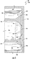
- FIG. 5 is an enlarged cross sectional side view of a portion of the bundled tube fuel nozzle 100 or one of the bundled tube fuel nozzle assemblies 104 as shown in FIGS. 3 and 4 , including a portion of the aft plate 112, a portion of wall 124 and a portion of the cooling air plenum 128 according to at least one embodiment of the present disclosure.
- a downstream end portion 146 of the wall 124 and/or a cool side 148 of the aft plate 112 which is axially spaced from the downstream or hot side 138 of the aft plate 112 defines a plurality of apertures 150 circumferentially spaced thereabout.
- FIG. 5 is an enlarged cross sectional side view of a portion of the bundled tube fuel nozzle 100 or one of the bundled tube fuel nozzle assemblies 104 as shown in FIGS. 3 and 4 , including a portion of the aft plate 112, a portion of wall 124 and a portion of the cooling air plenum 128 according to at
- each aperture 150 includes an inlet 152 defined along an inner surface 154 of the wall 124 and/or along the cool side 148 of the aft plate 112, and an outlet 156 defined along an outer surface 158 of the wall 124 and/or along the cool side 148 of the aft plate 112.
- one or more of the inlets 152 is disposed proximate or adjacent to the cool side 148 of the aft plate 112.
- one or more of the outlets 156 is oriented towards the cool side 148 of the aft plate 112.
- the apertures 150 provide for fluid communication from the cooling flow channel 126 to the cooling air plenum 128.
- FIG. 6 provides an operational flow diagram of the bundled tube fuel nozzle 100 according to at least one embodiment of the present disclosure.
- compressed air 200 such as the compressed air 26 from the compressor 14 enters the respective inlet 132 of each tube 130.
- Fuel 202 flows into and pressurizes the fuel plenum 116 via the fluid conduit 102 ( FIG. 2 ).
- the fuel 202 is injected into the premix flow passage 140 of one or more of the tubes 130 via fuel injection port(s) 142.
- the fuel 202 and compressed air 200 mix or blend together within the respective premix flow passages 140 to form a combustible fuel-air mixture 204 which exits the respective tube outlets 136 and is burned in the combustion chamber 42.
- An inert gas 206 such as compressed air 26 is injected or flows into the purge air plenum 120 via at least one inlet port 160 defined along the outer sleeve 114.
- the inert gas 206 flows across a portion of the tubes 130 that extends through the purge air plenum 120, thus providing cooling to the tubes 130 and/or the outer sleeve 114.
- the inert gas 206 may also purge any fuel which may have leaked from the fuel plenum 116 into the purge air plenum 120.
- a pressure differential between the purge air plenum 120 and the cooling air plenum 128 causes the inert gas 206 to travel through the cooling flow channel 126, towards the cold side 148 of the aft plate 112, into the respective inlets 152 of each aperture 150 and into the cooling air plenum 128.
- one or more of the outlets 156 of the apertures 150 may be oriented so as to direct the inert gas 206 across the cold side 148 of the aft plate 112 and/or around the tubes 130 within the cooling air plenum 128, thereby providing impingement, convection and/or conductive cooling of the aft plate 112 and/or the portion of tubes 130 disposed within the cooling air plenum 128.
- the inert gas 206 may be exhausted from the cooling air plenum 128 via exhaust ports defined along the outer sleeve 114.
- one or more exhaust ports 162 are defined along an outer band 164 portion of the outer sleeve 114.
- one or more exhaust ports 166 are defined along an inner band portion 168 of the outer sleeve 114.
- the inner band portion 168 of the outer sleeve 114 may extend at least partially around the center fuel nozzle 46.
- the exhaust ports 166 may provide cooling to a portion of the center fuel nozzle 46 and or may form a fluid seal between the inner band portion 168 and the center fuel nozzle 46.
Landscapes
- Engineering & Computer Science (AREA)
- Chemical & Material Sciences (AREA)
- Combustion & Propulsion (AREA)
- Mechanical Engineering (AREA)
- General Engineering & Computer Science (AREA)
- Turbine Rotor Nozzle Sealing (AREA)
- Gas Burners (AREA)
- Pre-Mixing And Non-Premixing Gas Burner (AREA)
Abstract
Description
- The present invention generally involves a bundled tube fuel nozzle for a gas turbine combustor. More specifically, the invention relates to a bundled tube fuel nozzle with internal cooling.
- Gas turbines are widely used in industrial and power generation operations. A gas turbine generally includes, in serial flow order, a compressor, a combustion section and a turbine. The combustion section may include multiple combustors annularly arranged around an outer casing. In operation, a working fluid such as ambient air is progressively compressed as it flows through the compressor. A portion of the compressed working fluid is routed from the compressor to each of the combustors where it is mixed with a fuel and burned in a combustion chamber or zone to produce combustion gases. The combustion gases are routed through the turbine along a hot gas path where thermal and/or kinetic energy is extracted from the combustion gases via turbine rotors blades coupled to a rotor shaft, thus causing the rotor shaft to rotate and produce work and/or thrust.
- Particular combustion systems utilize bundled tube type fuel nozzles for premixing a gaseous fuel with the compressed air upstream from the combustion zone. An aft plate of the bundled tube fuel nozzle is disposed at a downstream end of the bundled tube fuel nozzle. A "hot side" of the aft plate is positioned proximate to outlets of each tube of the bundle tube fuel nozzle. As such, the hot side of the aft plate is exposed to extreme heat from the combustion gases.
- Aspects and advantages are set forth below in the following description, or may be obvious from the description, or may be learned through practice.
- One embodiment of the present disclosure is a bundled tube fuel nozzle. The bundled tube fuel nozzle includes a forward plate, a first intermediate plate and an outer sleeve defining a fuel plenum therebetween. A second intermediate plate is axially spaced from the first intermediate plate and the first intermediate plate, the second intermediate plate and the outer sleeve define a purge air plenum therebetween. An aft plate is axially spaced from the second intermediate plate. The second intermediate plate, the aft plate and the outer sleeve define a cooling air plenum therebetween. A plurality of tubes extends through the forward plate, the fuel plenum, the first intermediate plate, the purge air plenum, the second intermediate plate, the cooling air plenum and the aft plate. An annular wall extends from the second intermediate plate to the aft plate and defines a cooling flow channel. A plurality of apertures is defined proximate to a cool side of the aft plate. The plurality of apertures provide for fluid communication between the cooling flow channel and the cooling air plenum.
- Another embodiment of the present disclosure is a combustor. The combustor includes an end cover coupled to an outer casing and a bundled tube fuel nozzle disposed within the outer casing and coupled to the end cover via one or more fluid conduits. The bundled tube fuel nozzle comprises a forward plate, a first intermediate plate and an outer sleeve that define a fuel plenum therebetween. The fuel plenum is in fluid communication with the fluid conduit. A second intermediate plate is axially spaced from the first intermediate plate. The first intermediate plate, the second intermediate plate and the outer sleeve define a purge air plenum therebetween. An aft plate is axially spaced from the second intermediate plate. The second intermediate plate, the aft plate and the outer sleeve define a cooling air plenum therebetween. A plurality of tubes extends through the forward plate, the fuel plenum, the first intermediate plate, the purge air plenum, the second intermediate plate, the cooling air plenum and the aft plate. An annular wall extends from the second intermediate plate to the aft plate and defines a cooling flow channel within the bundled tube fuel nozzle. A plurality of apertures is defined proximate to a cool side of the aft plate. The plurality of apertures provide for fluid communication between the cooling flow channel and the cooling air plenum.
- Another embodiment includes a combustor. The combustor includes an end cover coupled to an outer casing and a bundled tube fuel nozzle disposed within the outer casing and coupled to the end cover via a plurality of fluid conduits. The bundled tube fuel nozzle comprises a plurality of bundled tube fuel nozzle assemblies annularly arranged about a center fuel nozzle of the combustor. Each bundled tube fuel nozzle assembly comprises a forward plate, a first intermediate plate and an outer sleeve defining a fuel plenum therebetween. The fuel plenum is in fluid communication with at least one fluid conduit of the plurality of fluid conduits. A second intermediate plate is axially spaced from the first intermediate plate. The first intermediate plate, the second intermediate plate and the outer sleeve define a purge air plenum therebetween. An aft plate is axially spaced from the second intermediate plate. The second intermediate plate, the aft plate and the outer sleeve define a cooling air plenum therebetween. A plurality of tubes extends through the forward plate, the fuel plenum, the first intermediate plate, the purge air plenum, the second intermediate plate, the cooling air plenum and the aft plate. An annular wall extends from the second intermediate plate to the aft plate and defines a cooling flow channel within the bundled tube fuel nozzle. A plurality of apertures is defined proximate to a cool side of the aft plate. The plurality of apertures provides for fluid communication between the cooling flow channel and the cooling air plenum during operation of the combustor.
- Those of ordinary skill in the art will better appreciate the features and aspects of such embodiments, and others, upon review of the specification.
- A full and enabling disclosure of the of various embodiments is set forth more particularly in the remainder of the specification, including reference to the accompanying figures, in which:
-
FIG. 1 is a functional block diagram of an exemplary gas turbine that may incorporate various embodiments of the present disclosure; -
FIG. 2 is a simplified cross-section side view of an exemplary combustor as may incorporate various embodiments of the present disclosure; -
FIG. 3 is an upstream view of an exemplary bundled tube fuel nozzle according to one or more embodiments of the present disclosure; -
FIG. 4 is an enlarged cross sectional perspective view of a portion of the bundled tube fuel nozzle taken along section lines 4-4 as shown inFIG. 3 , according to at least one embodiment of the present disclosure; -
FIG. 5 is an enlarged view of a portion of the bundled tube fuel nozzle as shown in -
FIG. 4 , according to at least one embodiment of the present disclosure; and -
FIG. 6 is an operational diagram of the bundled tube fuel nozzle as shown inFIG. 4 , according to at least one embodiment of the present disclosure. - Reference will now be made in detail to present embodiments of the disclosure, one or more examples of which are illustrated in the accompanying drawings. The detailed description uses numerical and letter designations to refer to features in the drawings. Like or similar designations in the drawings and description have been used to refer to like or similar parts of the disclosure.
- As used herein, the terms "first", "second", and "third" may be used interchangeably to distinguish one component from another and are not intended to signify location or importance of the individual components. The terms "upstream" and "downstream" refer to the relative direction with respect to fluid flow in a fluid pathway. For example, "upstream" refers to the direction from which the fluid flows, and "downstream" refers to the direction to which the fluid flows. The term "radially" refers to the relative direction that is substantially perpendicular to an axial centerline of a particular component, and the term "axially" refers to the relative direction that is substantially parallel and/or coaxially aligned to an axial centerline of a particular component.
- The terminology used herein is for the purpose of describing particular embodiments only and is not intended to be limiting. As used herein, the singular forms "a", "an" and "the" are intended to include the plural forms as well, unless the context clearly indicates otherwise. It will be further understood that the terms "comprises" and/or "comprising," when used in this specification, specify the presence of stated features, integers, steps, operations, elements, and/or components, but do not preclude the presence or addition of one or more other features, integers, steps, operations, elements, components, and/or groups thereof.
- Each example is provided by way of explanation, not limitation. In fact, it will be apparent to those skilled in the art that modifications and variations can be made without departing from the scope or spirit thereof. For instance, features illustrated or described as part of one embodiment may be used on another embodiment to yield a still further embodiment. Thus, it is intended that the present disclosure covers such modifications and variations as come within the scope of the appended claims and their equivalents. Although exemplary embodiments of the present disclosure will be described generally in the context of a bundled tube fuel nozzle for a land based power generating gas turbine combustor for purposes of illustration, one of ordinary skill in the art will readily appreciate that embodiments of the present disclosure may be applied to any style or type of combustor for a turbomachine and are not limited to combustors or combustion systems for land based power generating gas turbines unless specifically recited in the claims.
- Referring now to the drawings,
FIG. 1 illustrates a schematic diagram of anexemplary gas turbine 10. Thegas turbine 10 generally includes aninlet section 12, acompressor 14 disposed downstream of theinlet section 12, at least onecombustor 16 disposed downstream of thecompressor 14, aturbine 18 disposed downstream of thecombustor 16 and anexhaust section 20 disposed downstream of theturbine 18. Additionally, thegas turbine 10 may include one ormore shafts 22 that couple thecompressor 14 to theturbine 18. - During operation,
air 24 flows through theinlet section 12 and into thecompressor 14 where theair 24 is progressively compressed, thus providingcompressed air 26 to thecombustor 16. At least a portion of thecompressed air 26 is mixed with afuel 28 within thecombustor 16 and burned to producecombustion gases 30. Thecombustion gases 30 flow from thecombustor 16 into theturbine 18, wherein energy (kinetic and/or thermal) is transferred from thecombustion gases 30 to rotor blades (not shown), thus causingshaft 22 to rotate. The mechanical rotational energy may then be used for various purposes such as to power thecompressor 14 and/or to generate electricity. Thecombustion gases 30 exiting theturbine 18 may then be exhausted from thegas turbine 10 via theexhaust section 20. - As shown in
FIG. 2 , thecombustor 16 may be at least partially surrounded anouter casing 32 such as a compressor discharge casing. Theouter casing 32 may at least partially define ahigh pressure plenum 34 that at least partially surrounds various components of thecombustor 16. Thehigh pressure plenum 34 may be in fluid communication with the compressor 14 (FIG. 1 ) so as to receive thecompressed air 26 therefrom. Anend cover 36 may be coupled to theouter casing 32. In particular embodiments, theouter casing 32 and theend cover 36 may at least partially define a head end volume orportion 38 of thecombustor 16. In particular embodiments, thehead end portion 38 is in fluid communication with thehigh pressure plenum 34 and/or thecompressor 14. One or more liners orducts 40 may at least partially define a combustion chamber orzone 42 for combusting the fuel-air mixture and/or may at least partially define ahot gas path 44 through the combustor for directing thecombustion gases 30 towards an inlet to theturbine 18. In particular embodiments, as shown inFIG. 2 , thecombustor 16 includes acenter fuel nozzle 46 coupled to theend cover 36 and extending axially towards thecombustion chamber 42 with respect to anaxial centerline 48 of thecombustor 16. - In various embodiments, the
combustor 16 includes a bundledtube fuel nozzle 100. As shown inFIG. 2 , thefuel nozzle 100 is disposed within theouter casing 32 downstream from and/or axially spaced from theend cover 36 with respect toaxial centerline 48 of thecombustor 16 and upstream from thecombustion chamber 42. In particular embodiments, the bundledtube fuel nozzle 100 is in fluid communication with agas fuel supply 50. In one embodiment, the bundledtube fuel nozzle 100 is in fluid communication with thegas fuel supply 50 via one or morefluid conduits 102. In particular embodiments, the fluid conduit(s) 102 may be fluidly coupled and/or connected at one end to theend cover 36. -
FIG. 3 provides an upstream view of an exemplary bundledtube fuel nozzle 100 according to at least one embodiment of the present disclosure.FIG. 4 provides a cross sectioned downstream perspective view of a portion of the bundledtube fuel nozzle 100 taken along section line 4-4 as shown inFIG. 3 , according to at least one embodiment of the present disclosure. Various embodiments of thecombustor 16 may include different arrangements of the bundledtube fuel nozzle 100 and is not limited to any particular arrangement unless otherwise specified in the claims. For example, in particular configurations as illustrated inFIG. 3 , the bundledtube fuel nozzle 100 includes multiple wedge shaped bundled tubefuel nozzle assemblies 104 annularly arranged with respect tocenterline 48. In particular embodiments, the bundledtube fuel nozzle 100 forms an annulus or fuel nozzle passage about a portion of the center fuel nozzle 46 (FIG. 1 ). - In at least one embodiment, as shown in
FIG. 4 , the bundledtube fuel nozzle 100 and/or each bundled tubefuel nozzle assembly 104, includes, in sequential order, aforward plate 106, a firstintermediate plate 108 axially spaced from theforward plate 106, a secondintermediate plate 110 axially spaced from the firstintermediate plate 108, anaft plate 112 axially spaced from the secondintermediate plate 110 and an outer shroud orsleeve 114 that extends about an outer perimeter or peripheral edge of theforward plate 106, the firstintermediate plate 108, the secondintermediate plate 110 and theaft plate 112. In at least one embodiment, theforward plate 106, firstintermediate plate 108, secondintermediate plate 110 and theaft plate 112 are wedge shaped with arcuate inner and outer sides. - In at least one embodiment, the
forward plate 106, the firstintermediate plate 108 and thesleeve 114 at least partially define afuel plenum 116 within the bundledtube fuel nozzle 100. Theforward plate 106 may define anopening 118 to thefuel plenum 116. Theopening 118 may be fluidly coupled to the fluid conduit 102 (FIG. 2 ). The firstintermediate plate 108, the secondintermediate plate 110 and thesleeve 114 at least partially define apurge air plenum 120 within the bundledtube fuel nozzle 100. - The second
intermediate plate 110 defines a hole orpassage 122. In particular embodiments thepassage 122 may be substantially aligned with theopening 118 of theforward plate 106. Anannular wall 124 extends axially from the secondintermediate plate 110 to theaft plate 112 and is aligned with thepassage 122. Thepassage 122 and thewall 124 at least partially form acooling flow channel 126 within the bundledtube fuel nozzle 100. The secondintermediate plate 110, theaft plate 112, thewall 124 and theouter sleeve 114 at least partially define a coolingair plenum 128 within the bundledtube fuel nozzle 100 and/or the bundled tubefuel nozzle assembly 104. - As shown in
FIG. 4 , the bundledtube fuel nozzle 100 and/or the bundled tubefuel nozzle assembly 104 includes a plurality oftubes 130 that extends through theforward plate 106, thefuel plenum 116, the firstintermediate plate 108, thepurge air plenum 120, the secondintermediate plate 110, the coolingair plenum 128 and through theaft plate 112. Eachtube 130 includes aninlet 132 defined at or upstream from anupstream side 134 of theforward plate 106 and anoutlet 136 defined at or downstream from a downstream orhot side 138 of theaft plate 112. Eachtube 130 defines apremix flow passage 140 through the bundledtube fuel nozzle 100 and/or the bundled tubefuel nozzle assembly 104. One or more of thetubes 130 includes at least onefuel injection port 142 which provides for fluid communication between thefuel plenum 116 and the respectivepremix flow passage 140. In at least one embodiment, as shown inFIG. 4 , the plurality oftubes 130 is annularly arranged around theopening 118 in theforward plate 106. -
FIG. 5 is an enlarged cross sectional side view of a portion of the bundledtube fuel nozzle 100 or one of the bundled tubefuel nozzle assemblies 104 as shown inFIGS. 3 and 4 , including a portion of theaft plate 112, a portion ofwall 124 and a portion of the coolingair plenum 128 according to at least one embodiment of the present disclosure. As shown inFIGS. 4 and5 , adownstream end portion 146 of thewall 124 and/or acool side 148 of theaft plate 112 which is axially spaced from the downstream orhot side 138 of theaft plate 112 defines a plurality ofapertures 150 circumferentially spaced thereabout. As shown in detail inFIG. 5 , eachaperture 150 includes aninlet 152 defined along aninner surface 154 of thewall 124 and/or along thecool side 148 of theaft plate 112, and anoutlet 156 defined along an outer surface 158 of thewall 124 and/or along thecool side 148 of theaft plate 112. In at least one embodiment, one or more of theinlets 152 is disposed proximate or adjacent to thecool side 148 of theaft plate 112. In at least one embodiment, one or more of theoutlets 156 is oriented towards thecool side 148 of theaft plate 112. During operation, theapertures 150 provide for fluid communication from thecooling flow channel 126 to the coolingair plenum 128. -
FIG. 6 provides an operational flow diagram of the bundledtube fuel nozzle 100 according to at least one embodiment of the present disclosure. During operation, as shown inFIG. 6 ,compressed air 200 such as thecompressed air 26 from thecompressor 14 enters therespective inlet 132 of eachtube 130.Fuel 202 flows into and pressurizes thefuel plenum 116 via the fluid conduit 102 (FIG. 2 ). Thefuel 202 is injected into thepremix flow passage 140 of one or more of thetubes 130 via fuel injection port(s) 142. Thefuel 202 andcompressed air 200 mix or blend together within the respectivepremix flow passages 140 to form a combustible fuel-air mixture 204 which exits therespective tube outlets 136 and is burned in thecombustion chamber 42. - An
inert gas 206 such ascompressed air 26 is injected or flows into thepurge air plenum 120 via at least oneinlet port 160 defined along theouter sleeve 114. Theinert gas 206 flows across a portion of thetubes 130 that extends through thepurge air plenum 120, thus providing cooling to thetubes 130 and/or theouter sleeve 114. Theinert gas 206 may also purge any fuel which may have leaked from thefuel plenum 116 into thepurge air plenum 120. A pressure differential between thepurge air plenum 120 and the coolingair plenum 128 causes theinert gas 206 to travel through thecooling flow channel 126, towards thecold side 148 of theaft plate 112, into therespective inlets 152 of eachaperture 150 and into the coolingair plenum 128. - As shown in
FIGS. 5 and6 collectively, one or more of theoutlets 156 of theapertures 150 may be oriented so as to direct theinert gas 206 across thecold side 148 of theaft plate 112 and/or around thetubes 130 within the coolingair plenum 128, thereby providing impingement, convection and/or conductive cooling of theaft plate 112 and/or the portion oftubes 130 disposed within the coolingair plenum 128. Theinert gas 206 may be exhausted from the coolingair plenum 128 via exhaust ports defined along theouter sleeve 114. In particular embodiments, one or moreexhaust ports 162 are defined along anouter band 164 portion of theouter sleeve 114. In particular embodiments, one or moreexhaust ports 166 are defined along aninner band portion 168 of theouter sleeve 114. Theinner band portion 168 of theouter sleeve 114 may extend at least partially around thecenter fuel nozzle 46. As such, theexhaust ports 166 may provide cooling to a portion of thecenter fuel nozzle 46 and or may form a fluid seal between theinner band portion 168 and thecenter fuel nozzle 46. - This written description uses examples to disclose the invention and also to enable any person skilled in the art to practice the invention, including making and using any devices or systems and performing any incorporated methods. The patentable scope of the invention is defined by the claims, and may include other examples that occur to those skilled in the art. Such other examples are intended to be within the scope of the claims if they include structural elements that do not differ from the literal language of the claims, or if they include equivalent structural elements with insubstantial differences from the literal language of the claims.
- Various aspects and embodiments of the present invention are defined by the following numbered clauses:
- 1. A bundled tube fuel nozzle, comprising:
- a forward plate, a first intermediate plate and an outer sleeve defining a fuel plenum therebetween;
- a second intermediate plate axially spaced from the first intermediate plate, wherein the first intermediate plate, the second intermediate plate and the outer sleeve define a purge air plenum therebetween;
- an aft plate axially spaced from the second intermediate plate, wherein the second intermediate plate, the aft plate and the outer sleeve define a cooling air plenum therebetween;
- a plurality of tubes that extends through the forward plate, the fuel plenum, the first intermediate plate, the purge air plenum, the second intermediate plate, the cooling air plenum and the aft plate;
- an annular wall that extends from the second intermediate plate to the aft plate, the annular wall defining a cooling flow channel; and
- a plurality of apertures defined proximate to a cool side of the aft plate, wherein the plurality of apertures provide for fluid communication between the cooling flow channel and the cooling air plenum.
- 2. The bundled tube fuel nozzle as in clause 1, wherein the apertures of the plurality of apertures are circumferentially spaced along the annular wall.
- 3. The bundled tube fuel nozzle as in any preceding clause, wherein one or more of the apertures of the plurality of apertures includes an outlet oriented towards the cool side of the aft plate.
- 4. The bundled tube fuel nozzle as in any preceding clause, wherein the outer sleeve defines an inlet port, wherein the inlet port provides for fluid communication into the purge air plenum.
- 5. The bundled tube fuel nozzle as in any preceding clause, wherein the outer sleeve defines one or more exhaust ports, wherein the one or more exhaust ports provide for fluid communication out of the cooling air plenum.
- 6. The bundled tube fuel nozzle as in any preceding clause, wherein at least one of the one or more exhaust ports is defined along an inner band portion of the outer sleeve.
- 7. The bundled tube fuel nozzle as in any preceding clause, wherein at least one of the one or more exhaust ports is defined along an outer band portion of the outer sleeve.
- 8. A combustor, comprising:
- an end cover coupled to an outer casing;
- a bundled tube fuel nozzle disposed within the outer casing and coupled to the end cover via one or more fluid conduits, wherein the bundled tube fuel nozzle comprises:
- a forward plate, a first intermediate plate and an outer sleeve defining a fuel plenum therebetween, wherein the fuel plenum is in fluid communication with the fluid conduit;
- a second intermediate plate axially spaced from the first intermediate plate, wherein the first intermediate plate, the second intermediate plate and the outer sleeve define a purge air plenum therebetween;
- an aft plate axially spaced from the second intermediate plate, wherein the second intermediate plate, the aft plate and the outer sleeve define a cooling air plenum therebetween;
- a plurality of tubes that extends through the forward plate, the fuel plenum, the first intermediate plate, the purge air plenum, the second intermediate plate, the cooling air plenum and the aft plate;
- an annular wall that extends from the second intermediate plate to the aft plate, the annular wall defining a cooling flow channel; and
- a plurality of apertures defined proximate to a cool side of the aft plate, wherein the plurality of apertures provide for fluid communication between the cooling flow channel and the cooling air plenum.
- 9. The combustor as in any preceding clause, wherein the apertures of the plurality of apertures are circumferentially spaced along the annular wall.
- 10. The combustor as in any preceding clause, wherein one or more of the apertures of the plurality of apertures includes an outlet oriented towards the cool side of the aft plate.
- 11. The combustor as in any preceding clause, wherein the outer sleeve defines an inlet port, wherein the inlet port provides for fluid communication into the purge air plenum.
- 12. The combustor as in any preceding clause, further comprising a center fuel nozzle coupled to the end cover, wherein the bundled tube fuel nozzle extends circumferentially around at least a portion of the center fuel nozzle.
- 13. The combustor as in any preceding clause, wherein the outer sleeve defines one or more exhaust ports, wherein the one or more exhaust ports provide for fluid communication out of the cooling air plenum.
- 14. The combustor as in any preceding clause, wherein at least one of the one or more exhaust ports is defined along an inner band portion of the outer sleeve.
- 15. The combustor as in any preceding clause, wherein at least one of the one or more exhaust ports is defined along an outer band portion of the outer sleeve.
- 16. A combustor, comprising:
- an end cover coupled to an outer casing;
- a bundled tube fuel nozzle disposed within the outer casing and coupled to the end cover via a plurality of fluid conduits, wherein the bundled tube fuel nozzle comprises a plurality of bundled tube fuel nozzle assemblies annularly arranged about a center fuel nozzle of the combustor, wherein each bundled tube fuel nozzle assembly comprises:
- a forward plate, a first intermediate plate and an outer sleeve defining a fuel plenum therebetween, wherein the fuel plenum is in fluid communication with at least one fluid conduit of the plurality of fluid conduits;
- a second intermediate plate axially spaced from the first intermediate plate, wherein the first intermediate plate, the second intermediate plate and the outer sleeve define a purge air plenum therebetween;
- an aft plate axially spaced from the second intermediate plate, wherein the second intermediate plate, the aft plate and the outer sleeve define a cooling air plenum therebetween;
- a plurality of tubes that extends through the forward plate, the fuel plenum, the first intermediate plate, the purge air plenum, the second intermediate plate, the cooling air plenum and the aft plate;
- an annular wall that extends from the second intermediate plate to the aft plate, the annular wall defining a cooling flow channel; and
- a plurality of apertures defined proximate to a cool side of the aft plate, wherein the plurality of apertures provide for fluid communication between the cooling flow channel and the cooling air plenum.
- 17. The combustor as in any preceding clause, wherein the apertures of the plurality of apertures are circumferentially spaced along the annular wall.
- 18. The combustor as in any preceding clause, wherein one or more of the apertures of the plurality of apertures includes an outlet oriented towards the cool side of the aft plate.
- 19. The combustor as in any preceding clause, wherein the outer sleeve defines an inlet port, wherein the inlet port provides for fluid communication into the purge air plenum.
- 20. The combustor as in any preceding clause, wherein the outer sleeve defines one or more exhaust ports that provide for fluid communication out of the cooling air plenum.
Claims (15)
- A bundled tube fuel nozzle (100), comprising:a forward plate (106), a first intermediate plate (108) and an outer sleeve (114) defining a fuel plenum (116) therebetween;a second intermediate plate (110) axially spaced from the first intermediate plate (108), wherein the first intermediate plate (108), the second intermediate plate (110) and the outer sleeve (114) define a purge air plenum (120) therebetween;an aft plate (112) axially spaced from the second intermediate plate (110), wherein the second intermediate plate (110), the aft plate (112) and the outer sleeve (114) define a cooling air plenum (128) therebetween;a plurality of tubes (130) that extends through the forward plate (106), the fuel plenum (116), the first intermediate plate (108), the purge air plenum (120), the second intermediate plate (110), the cooling air plenum (128) and the aft plate (112);an annular wall (124) that extends from the second intermediate plate (110) to the aft plate (112), the annular wall (124) defining a cooling flow channel (126); anda plurality of apertures (150) defined proximate to a cool side of the aft plate (112), wherein the plurality of apertures (150) provide for fluid communication between the cooling flow channel (126) and the cooling air plenum (128).
- The bundled tube fuel nozzle (100) as in claim 1, wherein the apertures (150) of the plurality of apertures (150) are circumferentially spaced along the annular wall (124).
- The bundled tube fuel nozzle (100) as in claim 1 or 2, wherein one or more of the apertures (150) of the plurality of apertures (150) includes an outlet (156) oriented towards the cool side of the aft plate (112).
- The bundled tube fuel nozzle (100) as in claim 1, 2 or 3, wherein the outer sleeve (114) defines an inlet port (160), wherein the inlet port (160) provides for fluid communication into the purge air plenum (120).
- The bundled tube fuel nozzle (100) as in any of claims 1 to 4, wherein the outer sleeve (114) defines one or more exhaust ports (162), wherein the one or more exhaust ports (162) provide for fluid communication out of the cooling air plenum (128).
- The bundled tube fuel nozzle (100) as in claim 5, wherein at least one of the one or more exhaust ports (162) is defined along an inner band portion of the outer sleeve (114).
- The bundled tube fuel nozzle (100) as in claim 5, wherein at least one of the one or more exhaust ports (162) is defined along an outer band portion of the outer sleeve (114).
- A combustor (16), comprising:an end cover (36) coupled to an outer casing (32);a bundled tube fuel nozzle (100) disposed within the outer casing (32) and coupled to the end cover (36) via one or more fluid conduits (102), wherein the bundled tube fuel nozzle (100) comprises:a forward plate (106), a first intermediate plate (108) and an outer sleeve (114) defining a fuel plenum (116) therebetween, wherein the fuel plenum (116) is in fluid communication with the fluid conduit (102);a second intermediate plate (110) axially spaced from the first intermediate plate (108), wherein the first intermediate plate (108), the second intermediate plate (110) and the outer sleeve (114) define a purge air plenum (120) therebetween;an aft plate (112) axially spaced from the second intermediate plate (110), wherein the second intermediate plate (110), the aft plate (112) and the outer sleeve (114) define a cooling air plenum (128) therebetween;a plurality of tubes (130) that extends through the forward plate (106), the fuel plenum (116), the first intermediate plate (108), the purge air plenum (120), the second intermediate plate (110), the cooling air plenum (128) and the aft plate (112);an annular wall (124) that extends from the second intermediate plate (110) to the aft plate (112), the annular wall (124) defining a cooling flow channel (126); anda plurality of apertures (150) defined proximate to a cool side of the aft plate (112), wherein the plurality of apertures (150) provide for fluid communication between the cooling flow channel (126) and the cooling air plenum (128).
- The combustor (16) as in claim 8, wherein the apertures (150) of the plurality of apertures (150) are circumferentially spaced along the annular wall (124).
- The combustor (16) as in claim 8 or 9, wherein one or more of the apertures (150) of the plurality of apertures (150) includes an outlet (156) oriented towards the cool side of the aft plate (112).
- The combustor (16) as in claim 8, 9 or 10, wherein the outer sleeve (114) defines an inlet port (160), wherein the inlet port (160) provides for fluid communication into the purge air plenum (120).
- The combustor (16) as in any of claims 8 to 11, further comprising a center fuel nozzle coupled to the end cover (36), wherein the bundled tube fuel nozzle (100) extends circumferentially around at least a portion of the center fuel nozzle.
- The combustor (16) as in any of claims 8 to 12, wherein the outer sleeve (114) defines one or more exhaust ports (162), wherein the one or more exhaust ports (162) provide for fluid communication out of the cooling air plenum (128).
- The combustor (16) as in claim 13, wherein at least one of the one or more exhaust ports (162) is defined along an inner band portion of the outer sleeve (114).
- The combustor (16) as in claim 13, wherein at least one of the one or more exhaust ports (162) is defined along an outer band portion of the outer sleeve (114).
Applications Claiming Priority (1)
| Application Number | Priority Date | Filing Date | Title |
|---|---|---|---|
| US15/060,688 US10309653B2 (en) | 2016-03-04 | 2016-03-04 | Bundled tube fuel nozzle with internal cooling |
Publications (2)
| Publication Number | Publication Date |
|---|---|
| EP3214373A1 true EP3214373A1 (en) | 2017-09-06 |
| EP3214373B1 EP3214373B1 (en) | 2018-09-05 |
Family
ID=58185344
Family Applications (1)
| Application Number | Title | Priority Date | Filing Date |
|---|---|---|---|
| EP17157949.3A Active EP3214373B1 (en) | 2016-03-04 | 2017-02-24 | Bundled tube fuel nozzle with internal cooling |
Country Status (4)
| Country | Link |
|---|---|
| US (1) | US10309653B2 (en) |
| EP (1) | EP3214373B1 (en) |
| JP (1) | JP6932006B2 (en) |
| CN (1) | CN107152700B (en) |
Cited By (1)
| Publication number | Priority date | Publication date | Assignee | Title |
|---|---|---|---|---|
| CN110168283A (en) * | 2017-01-12 | 2019-08-23 | 通用电气公司 | With the cooling fuel nozzle assembly in microchannel |
Families Citing this family (16)
| Publication number | Priority date | Publication date | Assignee | Title |
|---|---|---|---|---|
| KR101838822B1 (en) * | 2013-10-18 | 2018-03-14 | 미츠비시 쥬고교 가부시키가이샤 | Fuel injector |
| US20150285502A1 (en) * | 2014-04-08 | 2015-10-08 | General Electric Company | Fuel nozzle shroud and method of manufacturing the shroud |
| US10690350B2 (en) * | 2016-11-28 | 2020-06-23 | General Electric Company | Combustor with axially staged fuel injection |
| US11156362B2 (en) | 2016-11-28 | 2021-10-26 | General Electric Company | Combustor with axially staged fuel injection |
| US11994293B2 (en) | 2020-08-31 | 2024-05-28 | General Electric Company | Impingement cooling apparatus support structure and method of manufacture |
| US11994292B2 (en) | 2020-08-31 | 2024-05-28 | General Electric Company | Impingement cooling apparatus for turbomachine |
| US11460191B2 (en) | 2020-08-31 | 2022-10-04 | General Electric Company | Cooling insert for a turbomachine |
| US11614233B2 (en) | 2020-08-31 | 2023-03-28 | General Electric Company | Impingement panel support structure and method of manufacture |
| US11371702B2 (en) | 2020-08-31 | 2022-06-28 | General Electric Company | Impingement panel for a turbomachine |
| US11255545B1 (en) | 2020-10-26 | 2022-02-22 | General Electric Company | Integrated combustion nozzle having a unified head end |
| EP4027059A1 (en) * | 2021-01-12 | 2022-07-13 | Crosstown Power GmbH | Burner, combustor, and method for retrofitting a combustion appliance |
| KR102437977B1 (en) * | 2021-01-18 | 2022-08-30 | 두산에너빌리티 주식회사 | Nozzle assembly, Combustor and Gas turbine comprising the same |
| CN113701194B (en) * | 2021-08-16 | 2022-11-22 | 中国航发沈阳发动机研究所 | Premixing device for combustion chamber of gas turbine |
| US11767766B1 (en) | 2022-07-29 | 2023-09-26 | General Electric Company | Turbomachine airfoil having impingement cooling passages |
| KR102814686B1 (en) * | 2023-05-02 | 2025-05-28 | 두산에너빌리티 주식회사 | Nozzle for combustor, combustor, and gas turbine including the same |
| CN118729323B (en) * | 2024-09-03 | 2024-11-19 | 西安交通大学 | Air suction type engine combustor with rich oil working condition for spaceflight, working method and engine |
Citations (3)
| Publication number | Priority date | Publication date | Assignee | Title |
|---|---|---|---|---|
| US20150000284A1 (en) * | 2013-07-01 | 2015-01-01 | General Electric Company | Cap assembly for a bundled tube fuel injector |
| US20150076251A1 (en) * | 2013-09-19 | 2015-03-19 | General Electric Company | System for injecting fuel in a gas turbine combustor |
| US20150167982A1 (en) * | 2013-12-13 | 2015-06-18 | General Electric Company | Bundled tube fuel injector |
Family Cites Families (9)
| Publication number | Priority date | Publication date | Assignee | Title |
|---|---|---|---|---|
| US7007486B2 (en) * | 2003-03-26 | 2006-03-07 | The Boeing Company | Apparatus and method for selecting a flow mixture |
| US8112999B2 (en) * | 2008-08-05 | 2012-02-14 | General Electric Company | Turbomachine injection nozzle including a coolant delivery system |
| US8276385B2 (en) | 2009-10-08 | 2012-10-02 | General Electric Company | Staged multi-tube premixing injector |
| US8984887B2 (en) | 2011-09-25 | 2015-03-24 | General Electric Company | Combustor and method for supplying fuel to a combustor |
| US20130122436A1 (en) * | 2011-11-11 | 2013-05-16 | General Electric Company | Combustor and method for supplying fuel to a combustor |
| US9004912B2 (en) * | 2011-11-11 | 2015-04-14 | General Electric Company | Combustor and method for supplying fuel to a combustor |
| US8894407B2 (en) * | 2011-11-11 | 2014-11-25 | General Electric Company | Combustor and method for supplying fuel to a combustor |
| US9341376B2 (en) * | 2012-02-20 | 2016-05-17 | General Electric Company | Combustor and method for supplying fuel to a combustor |
| US9052112B2 (en) * | 2012-02-27 | 2015-06-09 | General Electric Company | Combustor and method for purging a combustor |
-
2016
- 2016-03-04 US US15/060,688 patent/US10309653B2/en active Active
-
2017
- 2017-02-22 JP JP2017030560A patent/JP6932006B2/en active Active
- 2017-02-24 EP EP17157949.3A patent/EP3214373B1/en active Active
- 2017-03-03 CN CN201710123891.3A patent/CN107152700B/en active Active
Patent Citations (3)
| Publication number | Priority date | Publication date | Assignee | Title |
|---|---|---|---|---|
| US20150000284A1 (en) * | 2013-07-01 | 2015-01-01 | General Electric Company | Cap assembly for a bundled tube fuel injector |
| US20150076251A1 (en) * | 2013-09-19 | 2015-03-19 | General Electric Company | System for injecting fuel in a gas turbine combustor |
| US20150167982A1 (en) * | 2013-12-13 | 2015-06-18 | General Electric Company | Bundled tube fuel injector |
Cited By (3)
| Publication number | Priority date | Publication date | Assignee | Title |
|---|---|---|---|---|
| CN110168283A (en) * | 2017-01-12 | 2019-08-23 | 通用电气公司 | With the cooling fuel nozzle assembly in microchannel |
| EP3568637A4 (en) * | 2017-01-12 | 2020-08-19 | General Electric Company | FUEL NOZZLE ARRANGEMENT WITH MICROCHANNEL COOLING |
| CN110168283B (en) * | 2017-01-12 | 2021-12-31 | 通用电气公司 | Fuel nozzle assembly with microchannel cooling |
Also Published As
| Publication number | Publication date |
|---|---|
| EP3214373B1 (en) | 2018-09-05 |
| JP6932006B2 (en) | 2021-09-08 |
| CN107152700B (en) | 2020-12-08 |
| CN107152700A (en) | 2017-09-12 |
| JP2017156078A (en) | 2017-09-07 |
| US20170254539A1 (en) | 2017-09-07 |
| US10309653B2 (en) | 2019-06-04 |
Similar Documents
| Publication | Publication Date | Title |
|---|---|---|
| EP3214373B1 (en) | Bundled tube fuel nozzle with internal cooling | |
| EP3171088B1 (en) | Bundled tube fuel nozzle assembly with liquid fuel capability | |
| CN205746972U (en) | The system of the cooling air in utilizing burner | |
| JP6176723B2 (en) | Combustor cap assembly | |
| CN103185354B (en) | Methods and systems for cooling a transition nozzle | |
| JP7242277B2 (en) | Thimble assembly for introducing cross-flow into the secondary combustion zone | |
| US10788215B2 (en) | Fuel nozzle assembly with flange orifice | |
| US20180149364A1 (en) | Combustor with axially staged fuel injection | |
| EP3220051A1 (en) | Bundled tube fuel nozzle with vibration damping | |
| US20180363906A1 (en) | Cooling of liquid fuel cartridge in gas turbine combustor head end | |
| EP2728263A1 (en) | A combustor and a method for cooling the combustor | |
| US20160054004A1 (en) | Combustor cap assembly | |
| EP3290805A1 (en) | Fuel nozzle assembly with resonator | |
| EP3086043A1 (en) | Premix pilot nozzle | |
| CN113864818B (en) | Combustor air flow path | |
| JP2017146087A (en) | Gas cartridge for premixed fuel nozzle | |
| US9890954B2 (en) | Combustor cap assembly | |
| US10634344B2 (en) | Fuel nozzle assembly with fuel purge | |
| US9964308B2 (en) | Combustor cap assembly | |
| EP3586061B1 (en) | Endcover assembly for a combustor | |
| US10408455B2 (en) | Fuel nozzle assembly with fuel inlet slots | |
| US11774093B2 (en) | Burner cooling structures | |
| US20170350321A1 (en) | Bundled Tube Fuel Nozzle Assembly with Tube Extensions |
Legal Events
| Date | Code | Title | Description |
|---|---|---|---|
| PUAI | Public reference made under article 153(3) epc to a published international application that has entered the european phase |
Free format text: ORIGINAL CODE: 0009012 |
|
| STAA | Information on the status of an ep patent application or granted ep patent |
Free format text: STATUS: THE APPLICATION HAS BEEN PUBLISHED |
|
| AK | Designated contracting states |
Kind code of ref document: A1 Designated state(s): AL AT BE BG CH CY CZ DE DK EE ES FI FR GB GR HR HU IE IS IT LI LT LU LV MC MK MT NL NO PL PT RO RS SE SI SK SM TR |
|
| AX | Request for extension of the european patent |
Extension state: BA ME |
|
| STAA | Information on the status of an ep patent application or granted ep patent |
Free format text: STATUS: REQUEST FOR EXAMINATION WAS MADE |
|
| 17P | Request for examination filed |
Effective date: 20180306 |
|
| RBV | Designated contracting states (corrected) |
Designated state(s): AL AT BE BG CH CY CZ DE DK EE ES FI FR GB GR HR HU IE IS IT LI LT LU LV MC MK MT NL NO PL PT RO RS SE SI SK SM TR |
|
| GRAP | Despatch of communication of intention to grant a patent |
Free format text: ORIGINAL CODE: EPIDOSNIGR1 |
|
| STAA | Information on the status of an ep patent application or granted ep patent |
Free format text: STATUS: GRANT OF PATENT IS INTENDED |
|
| INTG | Intention to grant announced |
Effective date: 20180424 |
|
| GRAS | Grant fee paid |
Free format text: ORIGINAL CODE: EPIDOSNIGR3 |
|
| GRAA | (expected) grant |
Free format text: ORIGINAL CODE: 0009210 |
|
| STAA | Information on the status of an ep patent application or granted ep patent |
Free format text: STATUS: THE PATENT HAS BEEN GRANTED |
|
| AK | Designated contracting states |
Kind code of ref document: B1 Designated state(s): AL AT BE BG CH CY CZ DE DK EE ES FI FR GB GR HR HU IE IS IT LI LT LU LV MC MK MT NL NO PL PT RO RS SE SI SK SM TR |
|
| REG | Reference to a national code |
Ref country code: GB Ref legal event code: FG4D |
|
| REG | Reference to a national code |
Ref country code: CH Ref legal event code: EP |
|
| REG | Reference to a national code |
Ref country code: AT Ref legal event code: REF Ref document number: 1038263 Country of ref document: AT Kind code of ref document: T Effective date: 20180915 |
|
| REG | Reference to a national code |
Ref country code: IE Ref legal event code: FG4D |
|
| REG | Reference to a national code |
Ref country code: DE Ref legal event code: R096 Ref document number: 602017000330 Country of ref document: DE |
|
| REG | Reference to a national code |
Ref country code: NL Ref legal event code: MP Effective date: 20180905 |
|
| REG | Reference to a national code |
Ref country code: LT Ref legal event code: MG4D |
|
| PG25 | Lapsed in a contracting state [announced via postgrant information from national office to epo] |
Ref country code: LT Free format text: LAPSE BECAUSE OF FAILURE TO SUBMIT A TRANSLATION OF THE DESCRIPTION OR TO PAY THE FEE WITHIN THE PRESCRIBED TIME-LIMIT Effective date: 20180905 Ref country code: NO Free format text: LAPSE BECAUSE OF FAILURE TO SUBMIT A TRANSLATION OF THE DESCRIPTION OR TO PAY THE FEE WITHIN THE PRESCRIBED TIME-LIMIT Effective date: 20181205 Ref country code: SE Free format text: LAPSE BECAUSE OF FAILURE TO SUBMIT A TRANSLATION OF THE DESCRIPTION OR TO PAY THE FEE WITHIN THE PRESCRIBED TIME-LIMIT Effective date: 20180905 Ref country code: BG Free format text: LAPSE BECAUSE OF FAILURE TO SUBMIT A TRANSLATION OF THE DESCRIPTION OR TO PAY THE FEE WITHIN THE PRESCRIBED TIME-LIMIT Effective date: 20181205 Ref country code: FI Free format text: LAPSE BECAUSE OF FAILURE TO SUBMIT A TRANSLATION OF THE DESCRIPTION OR TO PAY THE FEE WITHIN THE PRESCRIBED TIME-LIMIT Effective date: 20180905 Ref country code: GR Free format text: LAPSE BECAUSE OF FAILURE TO SUBMIT A TRANSLATION OF THE DESCRIPTION OR TO PAY THE FEE WITHIN THE PRESCRIBED TIME-LIMIT Effective date: 20181206 Ref country code: RS Free format text: LAPSE BECAUSE OF FAILURE TO SUBMIT A TRANSLATION OF THE DESCRIPTION OR TO PAY THE FEE WITHIN THE PRESCRIBED TIME-LIMIT Effective date: 20180905 |
|
| REG | Reference to a national code |
Ref country code: AT Ref legal event code: MK05 Ref document number: 1038263 Country of ref document: AT Kind code of ref document: T Effective date: 20180905 |
|
| PG25 | Lapsed in a contracting state [announced via postgrant information from national office to epo] |
Ref country code: HR Free format text: LAPSE BECAUSE OF FAILURE TO SUBMIT A TRANSLATION OF THE DESCRIPTION OR TO PAY THE FEE WITHIN THE PRESCRIBED TIME-LIMIT Effective date: 20180905 Ref country code: AL Free format text: LAPSE BECAUSE OF FAILURE TO SUBMIT A TRANSLATION OF THE DESCRIPTION OR TO PAY THE FEE WITHIN THE PRESCRIBED TIME-LIMIT Effective date: 20180905 Ref country code: LV Free format text: LAPSE BECAUSE OF FAILURE TO SUBMIT A TRANSLATION OF THE DESCRIPTION OR TO PAY THE FEE WITHIN THE PRESCRIBED TIME-LIMIT Effective date: 20180905 |
|
| PG25 | Lapsed in a contracting state [announced via postgrant information from national office to epo] |
Ref country code: CZ Free format text: LAPSE BECAUSE OF FAILURE TO SUBMIT A TRANSLATION OF THE DESCRIPTION OR TO PAY THE FEE WITHIN THE PRESCRIBED TIME-LIMIT Effective date: 20180905 Ref country code: RO Free format text: LAPSE BECAUSE OF FAILURE TO SUBMIT A TRANSLATION OF THE DESCRIPTION OR TO PAY THE FEE WITHIN THE PRESCRIBED TIME-LIMIT Effective date: 20180905 Ref country code: EE Free format text: LAPSE BECAUSE OF FAILURE TO SUBMIT A TRANSLATION OF THE DESCRIPTION OR TO PAY THE FEE WITHIN THE PRESCRIBED TIME-LIMIT Effective date: 20180905 Ref country code: NL Free format text: LAPSE BECAUSE OF FAILURE TO SUBMIT A TRANSLATION OF THE DESCRIPTION OR TO PAY THE FEE WITHIN THE PRESCRIBED TIME-LIMIT Effective date: 20180905 Ref country code: AT Free format text: LAPSE BECAUSE OF FAILURE TO SUBMIT A TRANSLATION OF THE DESCRIPTION OR TO PAY THE FEE WITHIN THE PRESCRIBED TIME-LIMIT Effective date: 20180905 Ref country code: ES Free format text: LAPSE BECAUSE OF FAILURE TO SUBMIT A TRANSLATION OF THE DESCRIPTION OR TO PAY THE FEE WITHIN THE PRESCRIBED TIME-LIMIT Effective date: 20180905 Ref country code: IS Free format text: LAPSE BECAUSE OF FAILURE TO SUBMIT A TRANSLATION OF THE DESCRIPTION OR TO PAY THE FEE WITHIN THE PRESCRIBED TIME-LIMIT Effective date: 20190105 Ref country code: PL Free format text: LAPSE BECAUSE OF FAILURE TO SUBMIT A TRANSLATION OF THE DESCRIPTION OR TO PAY THE FEE WITHIN THE PRESCRIBED TIME-LIMIT Effective date: 20180905 |
|
| PG25 | Lapsed in a contracting state [announced via postgrant information from national office to epo] |
Ref country code: SM Free format text: LAPSE BECAUSE OF FAILURE TO SUBMIT A TRANSLATION OF THE DESCRIPTION OR TO PAY THE FEE WITHIN THE PRESCRIBED TIME-LIMIT Effective date: 20180905 Ref country code: PT Free format text: LAPSE BECAUSE OF FAILURE TO SUBMIT A TRANSLATION OF THE DESCRIPTION OR TO PAY THE FEE WITHIN THE PRESCRIBED TIME-LIMIT Effective date: 20190105 Ref country code: SK Free format text: LAPSE BECAUSE OF FAILURE TO SUBMIT A TRANSLATION OF THE DESCRIPTION OR TO PAY THE FEE WITHIN THE PRESCRIBED TIME-LIMIT Effective date: 20180905 |
|
| REG | Reference to a national code |
Ref country code: DE Ref legal event code: R097 Ref document number: 602017000330 Country of ref document: DE |
|
| PLBE | No opposition filed within time limit |
Free format text: ORIGINAL CODE: 0009261 |
|
| STAA | Information on the status of an ep patent application or granted ep patent |
Free format text: STATUS: NO OPPOSITION FILED WITHIN TIME LIMIT |
|
| PG25 | Lapsed in a contracting state [announced via postgrant information from national office to epo] |
Ref country code: DK Free format text: LAPSE BECAUSE OF FAILURE TO SUBMIT A TRANSLATION OF THE DESCRIPTION OR TO PAY THE FEE WITHIN THE PRESCRIBED TIME-LIMIT Effective date: 20180905 |
|
| 26N | No opposition filed |
Effective date: 20190606 |
|
| PG25 | Lapsed in a contracting state [announced via postgrant information from national office to epo] |
Ref country code: SI Free format text: LAPSE BECAUSE OF FAILURE TO SUBMIT A TRANSLATION OF THE DESCRIPTION OR TO PAY THE FEE WITHIN THE PRESCRIBED TIME-LIMIT Effective date: 20180905 |
|
| PG25 | Lapsed in a contracting state [announced via postgrant information from national office to epo] |
Ref country code: LU Free format text: LAPSE BECAUSE OF NON-PAYMENT OF DUE FEES Effective date: 20190224 Ref country code: MC Free format text: LAPSE BECAUSE OF FAILURE TO SUBMIT A TRANSLATION OF THE DESCRIPTION OR TO PAY THE FEE WITHIN THE PRESCRIBED TIME-LIMIT Effective date: 20180905 |
|
| REG | Reference to a national code |
Ref country code: BE Ref legal event code: MM Effective date: 20190228 |
|
| REG | Reference to a national code |
Ref country code: IE Ref legal event code: MM4A |
|
| PG25 | Lapsed in a contracting state [announced via postgrant information from national office to epo] |
Ref country code: IE Free format text: LAPSE BECAUSE OF NON-PAYMENT OF DUE FEES Effective date: 20190224 |
|
| PG25 | Lapsed in a contracting state [announced via postgrant information from national office to epo] |
Ref country code: FR Free format text: LAPSE BECAUSE OF NON-PAYMENT OF DUE FEES Effective date: 20190228 Ref country code: BE Free format text: LAPSE BECAUSE OF NON-PAYMENT OF DUE FEES Effective date: 20190228 |
|
| PG25 | Lapsed in a contracting state [announced via postgrant information from national office to epo] |
Ref country code: TR Free format text: LAPSE BECAUSE OF FAILURE TO SUBMIT A TRANSLATION OF THE DESCRIPTION OR TO PAY THE FEE WITHIN THE PRESCRIBED TIME-LIMIT Effective date: 20180905 |
|
| PGFP | Annual fee paid to national office [announced via postgrant information from national office to epo] |
Ref country code: IT Payment date: 20200229 Year of fee payment: 4 |
|
| PG25 | Lapsed in a contracting state [announced via postgrant information from national office to epo] |
Ref country code: MT Free format text: LAPSE BECAUSE OF NON-PAYMENT OF DUE FEES Effective date: 20190224 |
|
| REG | Reference to a national code |
Ref country code: CH Ref legal event code: PL |
|
| PG25 | Lapsed in a contracting state [announced via postgrant information from national office to epo] |
Ref country code: CH Free format text: LAPSE BECAUSE OF NON-PAYMENT OF DUE FEES Effective date: 20200229 Ref country code: LI Free format text: LAPSE BECAUSE OF NON-PAYMENT OF DUE FEES Effective date: 20200229 |
|
| PG25 | Lapsed in a contracting state [announced via postgrant information from national office to epo] |
Ref country code: CY Free format text: LAPSE BECAUSE OF FAILURE TO SUBMIT A TRANSLATION OF THE DESCRIPTION OR TO PAY THE FEE WITHIN THE PRESCRIBED TIME-LIMIT Effective date: 20180905 |
|
| PG25 | Lapsed in a contracting state [announced via postgrant information from national office to epo] |
Ref country code: HU Free format text: LAPSE BECAUSE OF FAILURE TO SUBMIT A TRANSLATION OF THE DESCRIPTION OR TO PAY THE FEE WITHIN THE PRESCRIBED TIME-LIMIT; INVALID AB INITIO Effective date: 20170224 |
|
| GBPC | Gb: european patent ceased through non-payment of renewal fee |
Effective date: 20210224 |
|
| PG25 | Lapsed in a contracting state [announced via postgrant information from national office to epo] |
Ref country code: GB Free format text: LAPSE BECAUSE OF NON-PAYMENT OF DUE FEES Effective date: 20210224 |
|
| PG25 | Lapsed in a contracting state [announced via postgrant information from national office to epo] |
Ref country code: IT Free format text: LAPSE BECAUSE OF NON-PAYMENT OF DUE FEES Effective date: 20210224 |
|
| PG25 | Lapsed in a contracting state [announced via postgrant information from national office to epo] |
Ref country code: MK Free format text: LAPSE BECAUSE OF FAILURE TO SUBMIT A TRANSLATION OF THE DESCRIPTION OR TO PAY THE FEE WITHIN THE PRESCRIBED TIME-LIMIT Effective date: 20180905 |
|
| REG | Reference to a national code |
Ref country code: DE Ref legal event code: R081 Ref document number: 602017000330 Country of ref document: DE Owner name: GENERAL ELECTRIC TECHNOLOGY GMBH, CH Free format text: FORMER OWNER: GENERAL ELECTRIC COMPANY, SCHENECTADY, NY, US |
|
| PGFP | Annual fee paid to national office [announced via postgrant information from national office to epo] |
Ref country code: DE Payment date: 20260121 Year of fee payment: 10 |