EP3213997A1 - Dual mode aft light - Google Patents
Dual mode aft light Download PDFInfo
- Publication number
- EP3213997A1 EP3213997A1 EP16207530.3A EP16207530A EP3213997A1 EP 3213997 A1 EP3213997 A1 EP 3213997A1 EP 16207530 A EP16207530 A EP 16207530A EP 3213997 A1 EP3213997 A1 EP 3213997A1
- Authority
- EP
- European Patent Office
- Prior art keywords
- shield
- light
- distance
- emitter
- housing
- Prior art date
- Legal status (The legal status is an assumption and is not a legal conclusion. Google has not performed a legal analysis and makes no representation as to the accuracy of the status listed.)
- Granted
Links
Images

Classifications
-
- B—PERFORMING OPERATIONS; TRANSPORTING
- B64—AIRCRAFT; AVIATION; COSMONAUTICS
- B64D—EQUIPMENT FOR FITTING IN OR TO AIRCRAFT; FLIGHT SUITS; PARACHUTES; ARRANGEMENT OR MOUNTING OF POWER PLANTS OR PROPULSION TRANSMISSIONS IN AIRCRAFT
- B64D47/00—Equipment not otherwise provided for
- B64D47/02—Arrangements or adaptations of signal or lighting devices
- B64D47/06—Arrangements or adaptations of signal or lighting devices for indicating aircraft presence
-
- B—PERFORMING OPERATIONS; TRANSPORTING
- B64—AIRCRAFT; AVIATION; COSMONAUTICS
- B64D—EQUIPMENT FOR FITTING IN OR TO AIRCRAFT; FLIGHT SUITS; PARACHUTES; ARRANGEMENT OR MOUNTING OF POWER PLANTS OR PROPULSION TRANSMISSIONS IN AIRCRAFT
- B64D11/00—Passenger or crew accommodation; Flight-deck installations not otherwise provided for
-
- B—PERFORMING OPERATIONS; TRANSPORTING
- B64—AIRCRAFT; AVIATION; COSMONAUTICS
- B64D—EQUIPMENT FOR FITTING IN OR TO AIRCRAFT; FLIGHT SUITS; PARACHUTES; ARRANGEMENT OR MOUNTING OF POWER PLANTS OR PROPULSION TRANSMISSIONS IN AIRCRAFT
- B64D47/00—Equipment not otherwise provided for
- B64D47/02—Arrangements or adaptations of signal or lighting devices
-
- F—MECHANICAL ENGINEERING; LIGHTING; HEATING; WEAPONS; BLASTING
- F21—LIGHTING
- F21V—FUNCTIONAL FEATURES OR DETAILS OF LIGHTING DEVICES OR SYSTEMS THEREOF; STRUCTURAL COMBINATIONS OF LIGHTING DEVICES WITH OTHER ARTICLES, NOT OTHERWISE PROVIDED FOR
- F21V11/00—Screens not covered by groups F21V1/00, F21V3/00, F21V7/00 or F21V9/00
- F21V11/16—Screens not covered by groups F21V1/00, F21V3/00, F21V7/00 or F21V9/00 using sheets without apertures, e.g. fixed
Definitions
- the subject matter disclosed herein relates to lighting equipment, and more particularly, to lighting equipment for aircraft.
- Aircraft lighting is utilized within an aircraft to provide visibility to other aircraft and flight control personnel. Aircraft lighting can utilize multiple lighting patterns to provide desired illumination and to comply with aviation requirements. Often, aircraft lighting may require multiple lighting sources or additional complexity to provide the required lighting patterns.
- a dual mode light includes a housing, at least one first light emitter disposed in the housing, a plurality of second light emitters each disposed in the housing an emitter distance from the at least one first light emitter, a first shield disposed in the housing a first shield distance from the at least one first light emitter, wherein the first shield distance is less than the emitter distance, and a second shield disposed in the housing a second shield distance around the plurality of second light emitters.
- an aircraft includes an aircraft body having an aft portion, and a dual mode light disposed on the aft portion of the aircraft body, the dual mode light including a housing, at least one first light emitter disposed in the housing, a plurality of second light emitters each disposed in the housing an emitter distance from the at least one first light emitter, a first shield disposed in the housing a first shield distance from the at least one first light emitter, wherein the first shield distance is less than the emitter distance, and a second shield disposed in the housing a second shield distance around the plurality of second light emitters.
- inventions described above includes at least one first light emitter disposed in the housing, a plurality of second light emitters each disposed in the housing an emitter distance from the at least one first light emitter, a first shield disposed in the housing a first shield distance from the at least one first light emitter, wherein the first shield distance is less than the emitter distance, and a second shield disposed in the housing a second shield distance around the plurality of second light emitters.
- FIG. 1 shows an aircraft 100.
- the aircraft 100 includes a fore portion 101, an aft portion 102, and at least one dual mode aft light 110.
- the aircraft 100 can be any suitable aircraft, including, but not limited to fixed wing aircraft 100, rotary wing aircraft, etc.
- the aircraft 100 can utilize the dual mode aft light 110 to direct illumination where needed by regulations and operation requirements.
- the dual mode aft light 110 can provide two modes of illumination, including a wide pattern 102 and a directional pattern 104.
- the wide pattern 102 can be an omnidirectional pattern that is at least 70 degrees wide, while the directional pattern 104 is directed in a certain direction.
- the dual mode aft light 110 can provide both patterns 102, 104 without using multiple lights and while minimizing part count. This can reduce the amount of wiring and weight of the aircraft 100.
- the dual mode aft light 110 is shown.
- the dual mode aft light 110 includes a housing 111, an inner emitter 112, an inner shield 114, outer emitters 116, and an outer shield 118.
- the dual mode aft light 110 can provide a directional light pattern from the inner emitter 112 and a wide light pattern from the outer emitter 116.
- the housing 111 can contain the inner emitter 112, an inner shield 114, outer emitters 116, and an outer shield 118 in a common housing 111.
- the housing 111 can be formed of plastic, aluminum or any other suitable material.
- the housing 111 can be a circular shape or any other suitable shape.
- the inner emitter 112 can be centered within the housing 111.
- the housing 111 contains both the inner emitter 112 and the outer emitters 116 to provide for dual mode operation.
- the inner emitter 112 is located within the housing 111. In certain embodiments, the inner emitter 112 is centered within the housing 111.
- the inner emitter 112 can be any suitable light source, including, but not limited to a light emitting diode. In the illustrated embodiment, the inner emitter 112 is a solid state emitter. In certain embodiments, the inner emitter 112 can provide a light source with a virtual optical center coincident with the virtual optical center as the outer emitter 116.
- the location of the inner emitter 112 allows for a minimal number of emitters while minimizing shadows and undesirable pattern characteristics.
- the inner shield 114 works in conjunction with the inner emitter 112 to provide a directional light pattern.
- the inner shield 114 is a directional shield with geometric features to provide a sharp cutoff beyond the direction of the light pattern.
- the inner shield 114 is disposed an inner shield distance 113 from the inner emitter 112.
- the inner shield distance 113 can range between 0.5 centimeters to 1.0 centimeters.
- the inner shield 114 along with the inner emitter 112 is disposed within the outer emitters 116 to prevent or minimize negative light pattern effects of the outer emitters 116.
- the dual mode aft light 110 includes a plurality of outer emitters 116.
- the outer emitters 116 are light sources including, but not limited to, incandescent light sources, light emitted diodes, or any other suitable light sources.
- the outer emitters 116 are radially disposed from the center of the dual mode aft light 110.
- the outer emitters 116 are formed to create a virtual optical center that is coincident with the virtual optical center of the inner emitter 112.
- the outer emitters 116 can be disposed an outer emitter distance 115 from the center of the inner emitter 112. In certain embodiments, the outer emitter distance 115 is between 0.5 centimeters and 1 centimeter. In certain embodiments, the outer emitter distance 115 can be greater than 1 centimeter. In the illustrated embodiment, the outer emitters 116 are disposed radially outside of the inner shield 114 to minimize the light pattern created by the inner shield 114 during operation of the outer emitters 116. The outer emitter distance 115 allows the outer emitters 116 to "see around" the inner shield 114.
- the position of the outer emitters 116 eliminates or minimizes the need for a focusing optic, additional optical power, additional housings, additional components, etc., preventing additional complexity. Further, by positioning the outer emitters 116 outside of the inner shield 114 location, the outer emitters 116 are not required to be positioned in a precise manner.
- the light emitted from the outer emitters 116 is formed into the output pattern by the outer shield 118.
- the outer shield 118 is disposed an outer shield distance 117 from the outer emitters 116.
- the outer shield distance 117 can be 3.5 centimeters to 4 centimeters from the outer emitters 116.
- the outer shield 118 is disposed outside or around the plurality of outer emitters 116.
- the outer shield 118 in conjunction with the outer emitters 116 can provide an omnidirectional light pattern of approximately 70 degrees.
- the outer shield 118 in conjunction with the outer emitters 116 can provide an omnidirectional light pattern ranging between 60 to 80 degrees.
- the dual mode aft light 110 can provide the omnidirectional light pattern without requiring tight tolerances or additional equipment.
- the relationship between the inner shield distance 113 and the outer shield distance 117, along with the relationship between the inner emitter 112, the inner shield 114, the outer emitters 116, and the outer shield 118 allows the directional pattern created by the inner emitter 112 and the inner shield 114 to coexist with the omnidirectional pattern created by the outer emitters 116 and the outer shield 118 with minimal complication.
- the ratio between the inner shield distance 113 and the outer shield distance 117 is between .125 and .285.
- this ratio allows for both modes and output patterns to be contained in a single housing 111.
Landscapes
- Engineering & Computer Science (AREA)
- Aviation & Aerospace Engineering (AREA)
- General Engineering & Computer Science (AREA)
- Non-Portable Lighting Devices Or Systems Thereof (AREA)
- Optical Elements Other Than Lenses (AREA)
Abstract
Description
- This invention was made with government support with the United States Army under Contract No. W911W6-12-D-0006. The government therefore has certain rights in this invention.
- The subject matter disclosed herein relates to lighting equipment, and more particularly, to lighting equipment for aircraft.
- Aircraft lighting is utilized within an aircraft to provide visibility to other aircraft and flight control personnel. Aircraft lighting can utilize multiple lighting patterns to provide desired illumination and to comply with aviation requirements. Often, aircraft lighting may require multiple lighting sources or additional complexity to provide the required lighting patterns.
- According to an embodiment, a dual mode light includes a housing, at least one first light emitter disposed in the housing, a plurality of second light emitters each disposed in the housing an emitter distance from the at least one first light emitter, a first shield disposed in the housing a first shield distance from the at least one first light emitter, wherein the first shield distance is less than the emitter distance, and a second shield disposed in the housing a second shield distance around the plurality of second light emitters.
- According to an embodiment, an aircraft includes an aircraft body having an aft portion, and a dual mode light disposed on the aft portion of the aircraft body, the dual mode light including a housing, at least one first light emitter disposed in the housing, a plurality of second light emitters each disposed in the housing an emitter distance from the at least one first light emitter, a first shield disposed in the housing a first shield distance from the at least one first light emitter, wherein the first shield distance is less than the emitter distance, and a second shield disposed in the housing a second shield distance around the plurality of second light emitters.
- Technical function of the embodiments described above includes at least one first light emitter disposed in the housing, a plurality of second light emitters each disposed in the housing an emitter distance from the at least one first light emitter, a first shield disposed in the housing a first shield distance from the at least one first light emitter, wherein the first shield distance is less than the emitter distance, and a second shield disposed in the housing a second shield distance around the plurality of second light emitters.
- Other aspects, features, and techniques of the embodiments will become more apparent from the following description taken in conjunction with the drawings.
- The subject matter is particularly pointed out and distinctly claimed in the claims at the conclusion of the specification. The foregoing and other features, and advantages of the embodiments are apparent from the following detailed description taken in conjunction with the accompanying drawings in which like elements are numbered alike in the FIGURES:
-
FIG. 1 is a schematic view of one embodiment of an aircraft; and -
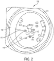
FIG. 2 is an isometric view of one embodiment of a dual mode aft light for use with the aircraft ofFIG. 1 . - Referring to the drawings,
FIG. 1 shows anaircraft 100. In the illustrated embodiment, theaircraft 100 includes afore portion 101, anaft portion 102, and at least one dualmode aft light 110. Theaircraft 100 can be any suitable aircraft, including, but not limited tofixed wing aircraft 100, rotary wing aircraft, etc. In the illustrated embodiment, theaircraft 100 can utilize the dualmode aft light 110 to direct illumination where needed by regulations and operation requirements. In the illustrated embodiment, the dualmode aft light 110 can provide two modes of illumination, including awide pattern 102 and adirectional pattern 104. In the illustrated embodiment, thewide pattern 102 can be an omnidirectional pattern that is at least 70 degrees wide, while thedirectional pattern 104 is directed in a certain direction. Advantageously, the dualmode aft light 110 can provide bothpatterns aircraft 100. - Referring to
FIG. 2 , the dualmode aft light 110 is shown. In the illustrated embodiment, the dualmode aft light 110 includes ahousing 111, aninner emitter 112, aninner shield 114,outer emitters 116, and anouter shield 118. In the illustrated embodiment, the dualmode aft light 110 can provide a directional light pattern from theinner emitter 112 and a wide light pattern from theouter emitter 116. - In the illustrated embodiment, the
housing 111 can contain theinner emitter 112, aninner shield 114,outer emitters 116, and anouter shield 118 in acommon housing 111. Thehousing 111 can be formed of plastic, aluminum or any other suitable material. Thehousing 111 can be a circular shape or any other suitable shape. Theinner emitter 112 can be centered within thehousing 111. Advantageously, thehousing 111 contains both theinner emitter 112 and theouter emitters 116 to provide for dual mode operation. - In the illustrated embodiment, the
inner emitter 112 is located within thehousing 111. In certain embodiments, theinner emitter 112 is centered within thehousing 111. Theinner emitter 112 can be any suitable light source, including, but not limited to a light emitting diode. In the illustrated embodiment, theinner emitter 112 is a solid state emitter. In certain embodiments, theinner emitter 112 can provide a light source with a virtual optical center coincident with the virtual optical center as theouter emitter 116. Advantageously, the location of theinner emitter 112 allows for a minimal number of emitters while minimizing shadows and undesirable pattern characteristics. - In the illustrated embodiment, the
inner shield 114 works in conjunction with theinner emitter 112 to provide a directional light pattern. In the illustrated embodiment, theinner shield 114 is a directional shield with geometric features to provide a sharp cutoff beyond the direction of the light pattern. In the illustrated embodiment, theinner shield 114 is disposed aninner shield distance 113 from theinner emitter 112. In certain embodiments, theinner shield distance 113 can range between 0.5 centimeters to 1.0 centimeters. In the illustrated embodiment, theinner shield 114 along with theinner emitter 112 is disposed within theouter emitters 116 to prevent or minimize negative light pattern effects of theouter emitters 116. - In the illustrated embodiment, the dual
mode aft light 110 includes a plurality ofouter emitters 116. In certain embodiments, theouter emitters 116 are light sources including, but not limited to, incandescent light sources, light emitted diodes, or any other suitable light sources. In the illustrated embodiment, theouter emitters 116 are radially disposed from the center of the dualmode aft light 110. In the illustrated embodiment, theouter emitters 116 are formed to create a virtual optical center that is coincident with the virtual optical center of theinner emitter 112. - In the illustrated embodiment, the
outer emitters 116 can be disposed anouter emitter distance 115 from the center of theinner emitter 112. In certain embodiments, theouter emitter distance 115 is between 0.5 centimeters and 1 centimeter. In certain embodiments, theouter emitter distance 115 can be greater than 1 centimeter. In the illustrated embodiment, theouter emitters 116 are disposed radially outside of theinner shield 114 to minimize the light pattern created by theinner shield 114 during operation of theouter emitters 116. Theouter emitter distance 115 allows theouter emitters 116 to "see around" theinner shield 114. Advantageously, the position of theouter emitters 116 eliminates or minimizes the need for a focusing optic, additional optical power, additional housings, additional components, etc., preventing additional complexity. Further, by positioning theouter emitters 116 outside of theinner shield 114 location, theouter emitters 116 are not required to be positioned in a precise manner. - In the illustrated embodiment, the light emitted from the
outer emitters 116 is formed into the output pattern by theouter shield 118. Theouter shield 118 is disposed anouter shield distance 117 from theouter emitters 116. In the illustrated embodiment, theouter shield distance 117 can be 3.5 centimeters to 4 centimeters from theouter emitters 116. In the illustrated embodiment, theouter shield 118 is disposed outside or around the plurality ofouter emitters 116. In the illustrated embodiment, theouter shield 118 in conjunction with theouter emitters 116 can provide an omnidirectional light pattern of approximately 70 degrees. In other embodiments, theouter shield 118 in conjunction with theouter emitters 116 can provide an omnidirectional light pattern ranging between 60 to 80 degrees. Advantageously, the dualmode aft light 110 can provide the omnidirectional light pattern without requiring tight tolerances or additional equipment. - In the illustrated embodiment, the relationship between the
inner shield distance 113 and theouter shield distance 117, along with the relationship between theinner emitter 112, theinner shield 114, theouter emitters 116, and theouter shield 118 allows the directional pattern created by theinner emitter 112 and theinner shield 114 to coexist with the omnidirectional pattern created by theouter emitters 116 and theouter shield 118 with minimal complication. In certain embodiments, the ratio between theinner shield distance 113 and theouter shield distance 117 is between .125 and .285. Advantageously, this ratio allows for both modes and output patterns to be contained in asingle housing 111. - The terminology used herein is for the purpose of describing particular embodiments only and is not intended to be limiting of the embodiments. While the description of the present embodiments has been presented for purposes of illustration and description, it is not intended to be exhaustive or limited to the embodiments in the form disclosed. Many modifications, variations, alterations, substitutions or equivalent arrangement not hereto described will be apparent to those of ordinary skill in the art without departing from the scope of the invention as defined by the claims. Additionally, while various embodiments have been described, it is to be understood that aspects may include only some of the described embodiments. Accordingly, the embodiments are not to be seen as limited by the foregoing description, but are only limited by the scope of the appended claims.
Claims (15)
- A dual mode light, comprising:a housing (111);at least one first light emitter (112) disposed in the housing;a plurality of second light emitters (116) each disposed in the housing an emitter distance from the at least one first light emitter;a first shield (114) disposed in the housing a first shield distance from the at least one first light emitter, wherein the first shield distance is less than the emitter distance; anda second shield (118) disposed in the housing a second shield distance around the plurality of second light emitters.
- The dual mode light of claim 1, wherein the first shield distance is between 0.5 centimeters and 1 centimeter.
- The dual mode light of claim 1, wherein the second shield distance is between 3.5 entimeters and 4 centimeters.
- The dual mode of light claim 1, wherein a distance ratio between the first shield distance and the second shield distance is between 0.125 and .285.
- The dual mode light of any preceding claim, wherein the at least one first light emitter (112) is a solid state emitter.
- The dual mode light of any preceding claim, wherein the first shield (114) is a directional shield.
- The dual mode light of any preceding claim, wherein the second shield (118) is an omnidirectional shield.
- The dual mode light of claim 7, wherein the second shield has a 60 degree to 80 degree pattern.
- The dual mode light of any preceding claim, wherein the at least one first light emitter and the plurality of second light emitters have a coincident virtual optical center.
- An aircraft, comprising:an aircraft body having an aft portion (102); anda dual mode light (110) disposed on the aft portion of the aircraft body, the dual mode light comprising:a housing (111);at least one first light emitter (112) disposed in the housing;a plurality of second light emitters (116) each disposed in the housing an emitter distance from the at least one first light emitter;a first shield (114) disposed in the housing a first shield distance from the at least one first light emitter, wherein the first shield distance is less than the emitter distance; anda second shield (118) disposed in the housing a second shield distance around the plurality of second light emitters.
- The aircraft of claim 10, wherein the first shield distance is between 0.5 centimeters and 1 centimeter.
- The aircraft of claim 10, wherein the second shield distance is between 3.5 centimeters and 4 centimeters.
- The aircraft of claim 10, wherein a distance ratio between the first shield distance and the second shield distance is between 0.125 and .285.
- The aircraft of any of claims 10 to 13, wherein the at least one first light emitter is a solid state emitter.
- The aircraft of any of claims 10 to 14, wherein the first shield is a directional shield.
Applications Claiming Priority (1)
| Application Number | Priority Date | Filing Date | Title |
|---|---|---|---|
| US15/057,706 US10472089B2 (en) | 2016-03-01 | 2016-03-01 | Dual mode aft light with a first light emitter and a plurality of second light emitters |
Publications (2)
| Publication Number | Publication Date |
|---|---|
| EP3213997A1 true EP3213997A1 (en) | 2017-09-06 |
| EP3213997B1 EP3213997B1 (en) | 2020-03-25 |
Family
ID=57749775
Family Applications (1)
| Application Number | Title | Priority Date | Filing Date |
|---|---|---|---|
| EP16207530.3A Active EP3213997B1 (en) | 2016-03-01 | 2016-12-30 | Dual mode aft light |
Country Status (5)
| Country | Link |
|---|---|
| US (1) | US10472089B2 (en) |
| EP (1) | EP3213997B1 (en) |
| CN (1) | CN107143801A (en) |
| BR (1) | BR102016030912B1 (en) |
| CA (1) | CA2953370C (en) |
Citations (5)
| Publication number | Priority date | Publication date | Assignee | Title |
|---|---|---|---|---|
| US5984494A (en) * | 1995-09-08 | 1999-11-16 | Jimmy G. Cook | Light shield for an illumination system |
| WO2002028711A2 (en) * | 2000-09-19 | 2002-04-11 | L-3 Communications Corporation | Dual mode light source for aircraft external lighting |
| US20030072165A1 (en) * | 2001-06-06 | 2003-04-17 | Rico Schulz | Light for an aircraft |
| EP1710493A2 (en) * | 2005-04-05 | 2006-10-11 | Osram Sylvania Inc. | Vitual point light source |
| EP2147863A2 (en) * | 2008-07-25 | 2010-01-27 | Honeywell International Inc. | Integrated position light overlap baffles |
Family Cites Families (5)
| Publication number | Priority date | Publication date | Assignee | Title |
|---|---|---|---|---|
| CN100436259C (en) * | 2003-12-08 | 2008-11-26 | 霍尼韦尔国际公司 | Multi-Platform Aircraft Front Position Indicator Utilizing LED-Based Light Sources |
| US7663506B2 (en) * | 2007-07-11 | 2010-02-16 | Honeywell International Inc. | Dual mode pilot director light utilizing visible and infrared light emitting diodes (LEDS) |
| JP4740934B2 (en) | 2007-12-07 | 2011-08-03 | シャープ株式会社 | Lighting device |
| CN102734689B (en) | 2011-03-31 | 2015-05-20 | 海洋王照明科技股份有限公司 | Enclosure road light |
| US8740424B2 (en) | 2011-05-20 | 2014-06-03 | Goodrich Lighting Systems Gmbh | Light for an aircraft |
-
2016
- 2016-03-01 US US15/057,706 patent/US10472089B2/en active Active
- 2016-12-29 CA CA2953370A patent/CA2953370C/en active Active
- 2016-12-29 BR BR102016030912-3A patent/BR102016030912B1/en active IP Right Grant
- 2016-12-30 CN CN201611257001.XA patent/CN107143801A/en active Pending
- 2016-12-30 EP EP16207530.3A patent/EP3213997B1/en active Active
Patent Citations (5)
| Publication number | Priority date | Publication date | Assignee | Title |
|---|---|---|---|---|
| US5984494A (en) * | 1995-09-08 | 1999-11-16 | Jimmy G. Cook | Light shield for an illumination system |
| WO2002028711A2 (en) * | 2000-09-19 | 2002-04-11 | L-3 Communications Corporation | Dual mode light source for aircraft external lighting |
| US20030072165A1 (en) * | 2001-06-06 | 2003-04-17 | Rico Schulz | Light for an aircraft |
| EP1710493A2 (en) * | 2005-04-05 | 2006-10-11 | Osram Sylvania Inc. | Vitual point light source |
| EP2147863A2 (en) * | 2008-07-25 | 2010-01-27 | Honeywell International Inc. | Integrated position light overlap baffles |
Also Published As
| Publication number | Publication date |
|---|---|
| BR102016030912B1 (en) | 2023-04-25 |
| US10472089B2 (en) | 2019-11-12 |
| US20170253347A1 (en) | 2017-09-07 |
| CN107143801A (en) | 2017-09-08 |
| CA2953370A1 (en) | 2017-09-01 |
| BR102016030912A2 (en) | 2017-09-19 |
| CA2953370C (en) | 2023-09-26 |
| EP3213997B1 (en) | 2020-03-25 |
Similar Documents
| Publication | Publication Date | Title |
|---|---|---|
| US10926889B2 (en) | Hybrid headlight for aircraft | |
| EP3219623A1 (en) | Aircraft anti-collision light | |
| EP2837566B1 (en) | Exterior aircraft light unit and aircraft comprising the exterior aircraft light unit | |
| US20160161073A1 (en) | Lighting system, in particular for a motor vehicle lighting member, comprising a light-emitting element offset from the light source | |
| US10435174B2 (en) | Optical device for lighting and/or signaling light for aircraft and light comprising such an optical device | |
| EP3213997B1 (en) | Dual mode aft light | |
| EP3476745B1 (en) | Aircraft beacon light and aircraft comprising the same | |
| EP3808662B1 (en) | Adjustable aiming aircraft light assembly | |
| US10301040B2 (en) | Dual mode aircraft light assembly | |
| US20200232619A1 (en) | Aircraft lamp | |
| US10024509B2 (en) | Exterior signaling and/or illuminating light and corresponding signaling and/or illuminating system | |
| US12078326B2 (en) | Aircraft light with support board and kinematic coupling fixture and aircraft comprising the same | |
| GB2540155A (en) | Navigation lights | |
| US20220219834A1 (en) | Set of Exterior Aircraft Lights and Aircraft Comprising such a Set of Exterior Aircraft Lights | |
| US10816161B1 (en) | Multifaceted discontinuous reflector | |
| US7918592B2 (en) | Integrated position light overlap baffles | |
| CN214405762U (en) | Landing light for aircraft | |
| EP4124794B1 (en) | Exterior aircraft light and aircraft comprising the same | |
| EP4491521A1 (en) | Aircraft light, aircraft comprising an aircraft light and method of manufacturing an aircraft light | |
| US20210033877A1 (en) | Laser aimer led lamp |
Legal Events
| Date | Code | Title | Description |
|---|---|---|---|
| PUAI | Public reference made under article 153(3) epc to a published international application that has entered the european phase |
Free format text: ORIGINAL CODE: 0009012 |
|
| STAA | Information on the status of an ep patent application or granted ep patent |
Free format text: STATUS: THE APPLICATION HAS BEEN PUBLISHED |
|
| AK | Designated contracting states |
Kind code of ref document: A1 Designated state(s): AL AT BE BG CH CY CZ DE DK EE ES FI FR GB GR HR HU IE IS IT LI LT LU LV MC MK MT NL NO PL PT RO RS SE SI SK SM TR |
|
| AX | Request for extension of the european patent |
Extension state: BA ME |
|
| STAA | Information on the status of an ep patent application or granted ep patent |
Free format text: STATUS: REQUEST FOR EXAMINATION WAS MADE |
|
| 17P | Request for examination filed |
Effective date: 20180306 |
|
| RBV | Designated contracting states (corrected) |
Designated state(s): AL AT BE BG CH CY CZ DE DK EE ES FI FR GB GR HR HU IE IS IT LI LT LU LV MC MK MT NL NO PL PT RO RS SE SI SK SM TR |
|
| STAA | Information on the status of an ep patent application or granted ep patent |
Free format text: STATUS: EXAMINATION IS IN PROGRESS |
|
| 17Q | First examination report despatched |
Effective date: 20190208 |
|
| GRAP | Despatch of communication of intention to grant a patent |
Free format text: ORIGINAL CODE: EPIDOSNIGR1 |
|
| STAA | Information on the status of an ep patent application or granted ep patent |
Free format text: STATUS: GRANT OF PATENT IS INTENDED |
|
| INTG | Intention to grant announced |
Effective date: 20191015 |
|
| GRAS | Grant fee paid |
Free format text: ORIGINAL CODE: EPIDOSNIGR3 |
|
| GRAA | (expected) grant |
Free format text: ORIGINAL CODE: 0009210 |
|
| STAA | Information on the status of an ep patent application or granted ep patent |
Free format text: STATUS: THE PATENT HAS BEEN GRANTED |
|
| AK | Designated contracting states |
Kind code of ref document: B1 Designated state(s): AL AT BE BG CH CY CZ DE DK EE ES FI FR GB GR HR HU IE IS IT LI LT LU LV MC MK MT NL NO PL PT RO RS SE SI SK SM TR |
|
| REG | Reference to a national code |
Ref country code: GB Ref legal event code: FG4D |
|
| REG | Reference to a national code |
Ref country code: DE Ref legal event code: R096 Ref document number: 602016032451 Country of ref document: DE |
|
| REG | Reference to a national code |
Ref country code: AT Ref legal event code: REF Ref document number: 1248291 Country of ref document: AT Kind code of ref document: T Effective date: 20200415 Ref country code: IE Ref legal event code: FG4D |
|
| PG25 | Lapsed in a contracting state [announced via postgrant information from national office to epo] |
Ref country code: RS Free format text: LAPSE BECAUSE OF FAILURE TO SUBMIT A TRANSLATION OF THE DESCRIPTION OR TO PAY THE FEE WITHIN THE PRESCRIBED TIME-LIMIT Effective date: 20200325 Ref country code: NO Free format text: LAPSE BECAUSE OF FAILURE TO SUBMIT A TRANSLATION OF THE DESCRIPTION OR TO PAY THE FEE WITHIN THE PRESCRIBED TIME-LIMIT Effective date: 20200625 Ref country code: FI Free format text: LAPSE BECAUSE OF FAILURE TO SUBMIT A TRANSLATION OF THE DESCRIPTION OR TO PAY THE FEE WITHIN THE PRESCRIBED TIME-LIMIT Effective date: 20200325 |
|
| PG25 | Lapsed in a contracting state [announced via postgrant information from national office to epo] |
Ref country code: BG Free format text: LAPSE BECAUSE OF FAILURE TO SUBMIT A TRANSLATION OF THE DESCRIPTION OR TO PAY THE FEE WITHIN THE PRESCRIBED TIME-LIMIT Effective date: 20200625 Ref country code: HR Free format text: LAPSE BECAUSE OF FAILURE TO SUBMIT A TRANSLATION OF THE DESCRIPTION OR TO PAY THE FEE WITHIN THE PRESCRIBED TIME-LIMIT Effective date: 20200325 Ref country code: GR Free format text: LAPSE BECAUSE OF FAILURE TO SUBMIT A TRANSLATION OF THE DESCRIPTION OR TO PAY THE FEE WITHIN THE PRESCRIBED TIME-LIMIT Effective date: 20200626 Ref country code: LV Free format text: LAPSE BECAUSE OF FAILURE TO SUBMIT A TRANSLATION OF THE DESCRIPTION OR TO PAY THE FEE WITHIN THE PRESCRIBED TIME-LIMIT Effective date: 20200325 Ref country code: SE Free format text: LAPSE BECAUSE OF FAILURE TO SUBMIT A TRANSLATION OF THE DESCRIPTION OR TO PAY THE FEE WITHIN THE PRESCRIBED TIME-LIMIT Effective date: 20200325 |
|
| REG | Reference to a national code |
Ref country code: NL Ref legal event code: MP Effective date: 20200325 |
|
| REG | Reference to a national code |
Ref country code: LT Ref legal event code: MG4D |
|
| PG25 | Lapsed in a contracting state [announced via postgrant information from national office to epo] |
Ref country code: NL Free format text: LAPSE BECAUSE OF FAILURE TO SUBMIT A TRANSLATION OF THE DESCRIPTION OR TO PAY THE FEE WITHIN THE PRESCRIBED TIME-LIMIT Effective date: 20200325 |
|
| PG25 | Lapsed in a contracting state [announced via postgrant information from national office to epo] |
Ref country code: SK Free format text: LAPSE BECAUSE OF FAILURE TO SUBMIT A TRANSLATION OF THE DESCRIPTION OR TO PAY THE FEE WITHIN THE PRESCRIBED TIME-LIMIT Effective date: 20200325 Ref country code: IS Free format text: LAPSE BECAUSE OF FAILURE TO SUBMIT A TRANSLATION OF THE DESCRIPTION OR TO PAY THE FEE WITHIN THE PRESCRIBED TIME-LIMIT Effective date: 20200725 Ref country code: LT Free format text: LAPSE BECAUSE OF FAILURE TO SUBMIT A TRANSLATION OF THE DESCRIPTION OR TO PAY THE FEE WITHIN THE PRESCRIBED TIME-LIMIT Effective date: 20200325 Ref country code: CZ Free format text: LAPSE BECAUSE OF FAILURE TO SUBMIT A TRANSLATION OF THE DESCRIPTION OR TO PAY THE FEE WITHIN THE PRESCRIBED TIME-LIMIT Effective date: 20200325 Ref country code: RO Free format text: LAPSE BECAUSE OF FAILURE TO SUBMIT A TRANSLATION OF THE DESCRIPTION OR TO PAY THE FEE WITHIN THE PRESCRIBED TIME-LIMIT Effective date: 20200325 Ref country code: PT Free format text: LAPSE BECAUSE OF FAILURE TO SUBMIT A TRANSLATION OF THE DESCRIPTION OR TO PAY THE FEE WITHIN THE PRESCRIBED TIME-LIMIT Effective date: 20200818 Ref country code: SM Free format text: LAPSE BECAUSE OF FAILURE TO SUBMIT A TRANSLATION OF THE DESCRIPTION OR TO PAY THE FEE WITHIN THE PRESCRIBED TIME-LIMIT Effective date: 20200325 Ref country code: EE Free format text: LAPSE BECAUSE OF FAILURE TO SUBMIT A TRANSLATION OF THE DESCRIPTION OR TO PAY THE FEE WITHIN THE PRESCRIBED TIME-LIMIT Effective date: 20200325 |
|
| REG | Reference to a national code |
Ref country code: AT Ref legal event code: MK05 Ref document number: 1248291 Country of ref document: AT Kind code of ref document: T Effective date: 20200325 |
|
| REG | Reference to a national code |
Ref country code: DE Ref legal event code: R097 Ref document number: 602016032451 Country of ref document: DE |
|
| PG25 | Lapsed in a contracting state [announced via postgrant information from national office to epo] |
Ref country code: DK Free format text: LAPSE BECAUSE OF FAILURE TO SUBMIT A TRANSLATION OF THE DESCRIPTION OR TO PAY THE FEE WITHIN THE PRESCRIBED TIME-LIMIT Effective date: 20200325 Ref country code: AT Free format text: LAPSE BECAUSE OF FAILURE TO SUBMIT A TRANSLATION OF THE DESCRIPTION OR TO PAY THE FEE WITHIN THE PRESCRIBED TIME-LIMIT Effective date: 20200325 Ref country code: IT Free format text: LAPSE BECAUSE OF FAILURE TO SUBMIT A TRANSLATION OF THE DESCRIPTION OR TO PAY THE FEE WITHIN THE PRESCRIBED TIME-LIMIT Effective date: 20200325 Ref country code: ES Free format text: LAPSE BECAUSE OF FAILURE TO SUBMIT A TRANSLATION OF THE DESCRIPTION OR TO PAY THE FEE WITHIN THE PRESCRIBED TIME-LIMIT Effective date: 20200325 |
|
| PLBE | No opposition filed within time limit |
Free format text: ORIGINAL CODE: 0009261 |
|
| STAA | Information on the status of an ep patent application or granted ep patent |
Free format text: STATUS: NO OPPOSITION FILED WITHIN TIME LIMIT |
|
| PG25 | Lapsed in a contracting state [announced via postgrant information from national office to epo] |
Ref country code: PL Free format text: LAPSE BECAUSE OF FAILURE TO SUBMIT A TRANSLATION OF THE DESCRIPTION OR TO PAY THE FEE WITHIN THE PRESCRIBED TIME-LIMIT Effective date: 20200325 |
|
| 26N | No opposition filed |
Effective date: 20210112 |
|
| PG25 | Lapsed in a contracting state [announced via postgrant information from national office to epo] |
Ref country code: SI Free format text: LAPSE BECAUSE OF FAILURE TO SUBMIT A TRANSLATION OF THE DESCRIPTION OR TO PAY THE FEE WITHIN THE PRESCRIBED TIME-LIMIT Effective date: 20200325 |
|
| REG | Reference to a national code |
Ref country code: DE Ref legal event code: R119 Ref document number: 602016032451 Country of ref document: DE |
|
| REG | Reference to a national code |
Ref country code: CH Ref legal event code: PL |
|
| PG25 | Lapsed in a contracting state [announced via postgrant information from national office to epo] |
Ref country code: MC Free format text: LAPSE BECAUSE OF FAILURE TO SUBMIT A TRANSLATION OF THE DESCRIPTION OR TO PAY THE FEE WITHIN THE PRESCRIBED TIME-LIMIT Effective date: 20200325 |
|
| REG | Reference to a national code |
Ref country code: BE Ref legal event code: MM Effective date: 20201231 |
|
| PG25 | Lapsed in a contracting state [announced via postgrant information from national office to epo] |
Ref country code: IE Free format text: LAPSE BECAUSE OF NON-PAYMENT OF DUE FEES Effective date: 20201230 Ref country code: LU Free format text: LAPSE BECAUSE OF NON-PAYMENT OF DUE FEES Effective date: 20201230 |
|
| PG25 | Lapsed in a contracting state [announced via postgrant information from national office to epo] |
Ref country code: CH Free format text: LAPSE BECAUSE OF NON-PAYMENT OF DUE FEES Effective date: 20201231 Ref country code: DE Free format text: LAPSE BECAUSE OF NON-PAYMENT OF DUE FEES Effective date: 20210701 Ref country code: LI Free format text: LAPSE BECAUSE OF NON-PAYMENT OF DUE FEES Effective date: 20201231 |
|
| PG25 | Lapsed in a contracting state [announced via postgrant information from national office to epo] |
Ref country code: TR Free format text: LAPSE BECAUSE OF FAILURE TO SUBMIT A TRANSLATION OF THE DESCRIPTION OR TO PAY THE FEE WITHIN THE PRESCRIBED TIME-LIMIT Effective date: 20200325 Ref country code: MT Free format text: LAPSE BECAUSE OF FAILURE TO SUBMIT A TRANSLATION OF THE DESCRIPTION OR TO PAY THE FEE WITHIN THE PRESCRIBED TIME-LIMIT Effective date: 20200325 Ref country code: CY Free format text: LAPSE BECAUSE OF FAILURE TO SUBMIT A TRANSLATION OF THE DESCRIPTION OR TO PAY THE FEE WITHIN THE PRESCRIBED TIME-LIMIT Effective date: 20200325 |
|
| PG25 | Lapsed in a contracting state [announced via postgrant information from national office to epo] |
Ref country code: MK Free format text: LAPSE BECAUSE OF FAILURE TO SUBMIT A TRANSLATION OF THE DESCRIPTION OR TO PAY THE FEE WITHIN THE PRESCRIBED TIME-LIMIT Effective date: 20200325 Ref country code: AL Free format text: LAPSE BECAUSE OF FAILURE TO SUBMIT A TRANSLATION OF THE DESCRIPTION OR TO PAY THE FEE WITHIN THE PRESCRIBED TIME-LIMIT Effective date: 20200325 |
|
| PG25 | Lapsed in a contracting state [announced via postgrant information from national office to epo] |
Ref country code: BE Free format text: LAPSE BECAUSE OF NON-PAYMENT OF DUE FEES Effective date: 20201231 |
|
| PGFP | Annual fee paid to national office [announced via postgrant information from national office to epo] |
Ref country code: GB Payment date: 20251119 Year of fee payment: 10 |
|
| P01 | Opt-out of the competence of the unified patent court (upc) registered |
Free format text: CASE NUMBER: UPC_APP_0016793_3213997/2025 Effective date: 20251210 |
|
| PGFP | Annual fee paid to national office [announced via postgrant information from national office to epo] |
Ref country code: FR Payment date: 20251119 Year of fee payment: 10 |