EP3211970A1 - Led driving output end capacitor protection circuit - Google Patents
Led driving output end capacitor protection circuit Download PDFInfo
- Publication number
- EP3211970A1 EP3211970A1 EP15863014.5A EP15863014A EP3211970A1 EP 3211970 A1 EP3211970 A1 EP 3211970A1 EP 15863014 A EP15863014 A EP 15863014A EP 3211970 A1 EP3211970 A1 EP 3211970A1
- Authority
- EP
- European Patent Office
- Prior art keywords
- output terminal
- terminal capacitor
- protective circuit
- voltage
- switching element
- Prior art date
- Legal status (The legal status is an assumption and is not a legal conclusion. Google has not performed a legal analysis and makes no representation as to the accuracy of the status listed.)
- Withdrawn
Links
Images
Classifications
-
- H—ELECTRICITY
- H05—ELECTRIC TECHNIQUES NOT OTHERWISE PROVIDED FOR
- H05B—ELECTRIC HEATING; ELECTRIC LIGHT SOURCES NOT OTHERWISE PROVIDED FOR; CIRCUIT ARRANGEMENTS FOR ELECTRIC LIGHT SOURCES, IN GENERAL
- H05B47/00—Circuit arrangements for operating light sources in general, i.e. where the type of light source is not relevant
- H05B47/20—Responsive to malfunctions or to light source life; for protection
- H05B47/24—Circuit arrangements for protecting against overvoltage
-
- H—ELECTRICITY
- H05—ELECTRIC TECHNIQUES NOT OTHERWISE PROVIDED FOR
- H05B—ELECTRIC HEATING; ELECTRIC LIGHT SOURCES NOT OTHERWISE PROVIDED FOR; CIRCUIT ARRANGEMENTS FOR ELECTRIC LIGHT SOURCES, IN GENERAL
- H05B45/00—Circuit arrangements for operating light-emitting diodes [LED]
- H05B45/50—Circuit arrangements for operating light-emitting diodes [LED] responsive to malfunctions or undesirable behaviour of LEDs; responsive to LED life; Protective circuits
Definitions
- the present invention relates to a light-emitting diode (LED) driver circuit, in particular to a protective circuit for an output terminal capacitor of an LED driver.
- LED light-emitting diode
- An LED driver circuit mostly has a fixed output circuit topology, and its output terminal has a capacitor element.
- a buck circuit topology has a simple wiring architecture and a low cost of an overall structure, and is widely applied in LED self-rectifying lamps.
- a conventional LED driver circuit may have the following two unusual situations: 1. an abnormal short circuit of a power tube; and 2. an open output circuit (caused by abnormal conditions such as damage of an LED and disconnection of output lines, etc.). The abnormal situations may result in a large voltage at an output terminal, and hence result in the damage of an output terminal capacitor.
- an improved protective circuit for an output terminal capacitor of an LED driver needs to be provided to protect the output terminal capacitor.
- An objective of the present invention is to provide a protective circuit for an output terminal capacitor of an LED driver.
- a protective circuit for an output terminal capacitor of an LED driver comprising a switching element, a voltage dividing unit and a one-way conduction unit, wherein the switching element is in parallel connection with the output terminal capacitor, the one-way conduction unit is connected between the switching element and the output terminal capacitor, the switching element is switched on when a voltage exceeds a threshold so as to establish a short circuit between two ends of the output terminal capacitor and prevent an excessively large voltage from being applied to the output terminal capacitor, and the one-way conduction unit allows a current to flow across the output terminal capacitor from the protective circuit by a one-way conduction.
- the protective circuit further comprises a threshold-voltage conduction unit.
- the threshold-voltage conduction unit is connected between the voltage dividing unit and the switching element and is switched on when a voltage at two ends of the protective circuit exceeds a certain value.
- the threshold-voltage conduction unit is a triode.
- the protective circuit further comprises a filter capacitor.
- One end of the filter capacitor is connected between the threshold-voltage conduction unit and the switching element, and another end of the filter capacitor is connected with a connection point of the switching element and the output terminal capacitor.
- the one-way conduction unit is a diode.
- the switching element is a thyristor.
- the protective circuit is applied to an output terminal of a buck topology circuit.
- the LED driver includes an LED driver circuit provided with the buck topology circuit.
- the protective circuit for the output terminal capacitor of the LED driver provided by the present invention has the following advantages: not only the output terminal capacitor can be effectively protected, but also the current will not flow back to damage the switching element in the protective circuit when the output terminal capacitor has a high voltage.
- the present invention provides a protective circuit 1 for an output terminal capacitor of an LED driver.
- the protective circuit 1 is connected to two sides of an output terminal capacitor EC1, and comprises a switching element SCR1, a voltage dividing unit 11 and a one-way conduction unit D2.
- the switching element SCR1 is in parallel connection with the output terminal capacitor Etc1; the one-way conduction unit D2 is connected between the switching element SCR1 and the output terminal capacitor EC1; the switching element SCR1 is switched on when a voltage exceeds a threshold, so as to establish a short circuit between two ends of the output terminal capacitor EC1 and prevent an excessively large voltage from being applied to the output terminal capacitor EC1; and the one-way conduction unit D2 allows a current to flow across the output terminal capacitor EC1 from the protective circuit 1 by a one-way conduction.
- the one-way conduction unit D2 prevents the voltage released at the two ends of the output terminal capacitor EC1 from being applied to the protective circuit 1 in an opposite direction, so as to protect the switching element SCR1 of the protective circuit 1 from being damaged due to an excessively large voltage.
- An element indicated in the present invention refers to not only one independent electronic element, but also may refer to a circuit including a plurality of electronic elements.
- the switching element SCR1 is a thyristor. In other embodiments, the switching element SCR1 may be designed to be other elements or circuits with a threshold-voltage conduction function as needed.
- the one-way conduction unit D2 is a diode. In other embodiments, the one-way conduction unit D2 may also be other elements or circuits capable of achieving one-way conduction.
- the protective circuit 1 further comprises a threshold-voltage conduction unit ZD1.
- the threshold-voltage conduction unit ZD1 is connected between the voltage dividing unit 11 and the switching element SCR1, and is switched on when the voltage at the two ends of the protective circuit 1 exceeds a certain value.
- the threshold-voltage conduction unit ZD1 is switched on, and then the switching element SCR1 is switched on.
- the threshold-voltage conduction unit ZD1 is a triode, specifically for example, a voltage stabilizing triode.
- the threshold-voltage conduction unit ZD1 may also be other elements or circuits capable of achieving the threshold-voltage conduction.
- the voltage dividing unit 11 includes a first resistor R1 and a second resistor R2; and one end of the threshold-voltage conduction unit ZD1 is connected with the switching element SCR1, and another end of the threshold-voltage conduction unit ZD1 is connected between the first resistor R1 and the second resistor R2. In other embodiments, the voltage dividing unit 11 may also be adjusted as needed.
- the protective circuit 1 further comprises a filter capacitor C2.
- One end of the filter capacitor C2 is connected between the threshold-voltage conduction unit ZD1 and the switching element SCR1, and another end of the filter capacitor C2 is connected to a connection point between the switching element SCR1 and the output terminal capacitor EC1.
- the filter capacitor C2 is used for preventing incorrect operations of the protective circuit 1 caused by interference noise signals.
- the protective circuit 1 for the output terminal capacitor of the LED driver provided in the invention is mostly applied to an output terminal of an LED driver circuit 3 provided with a buck topology circuit 2.
- the protective circuit 1 for the output terminal capacitor of the LED driver provided in the invention may also be applied in other topology circuits.
- the output voltage is raised; the output voltage after being divided by the first resistor R1 and the second resistor R2 breaks down the threshold-voltage conduction unit ZD1; and the switching element SCR1 is switched on as the voltage reaches the trigger threshold.
- the one-way conduction unit D2 prevents energy stored on the output terminal capacitor EC1 from being recharged into the switching element SCR1, so as to prevent the switching element SCR1 from being damaged by an excessively large instantaneous current due to the conduction short circuit.
- the one-way conduction unit D2 prevents energy stored on the output terminal capacitor EC1 from being recharged into the switching element SCR1, so as to prevent the switching element SCR1 from being damaged by an excessively large instantaneous current due to the conduction short circuit.
Landscapes
- Circuit Arrangement For Electric Light Sources In General (AREA)
- Led Devices (AREA)
Abstract
Description
- The present invention relates to a light-emitting diode (LED) driver circuit, in particular to a protective circuit for an output terminal capacitor of an LED driver.
- An LED driver circuit mostly has a fixed output circuit topology, and its output terminal has a capacitor element. For example, a buck circuit topology has a simple wiring architecture and a low cost of an overall structure, and is widely applied in LED self-rectifying lamps. However, a conventional LED driver circuit may have the following two unusual situations: 1. an abnormal short circuit of a power tube; and 2. an open output circuit (caused by abnormal conditions such as damage of an LED and disconnection of output lines, etc.). The abnormal situations may result in a large voltage at an output terminal, and hence result in the damage of an output terminal capacitor.
- Therefore, in order to overcome the above defects, an improved protective circuit for an output terminal capacitor of an LED driver needs to be provided to protect the output terminal capacitor.
- An objective of the present invention is to provide a protective circuit for an output terminal capacitor of an LED driver.
- In order to achieve the above objective, the present invention adopts the following technical proposal: a protective circuit for an output terminal capacitor of an LED driver, with the protective circuit being connected to two sides of the output terminal capacitor, comprising a switching element, a voltage dividing unit and a one-way conduction unit, wherein the switching element is in parallel connection with the output terminal capacitor, the one-way conduction unit is connected between the switching element and the output terminal capacitor, the switching element is switched on when a voltage exceeds a threshold so as to establish a short circuit between two ends of the output terminal capacitor and prevent an excessively large voltage from being applied to the output terminal capacitor, and the one-way conduction unit allows a current to flow across the output terminal capacitor from the protective circuit by a one-way conduction.
- Preferably, the protective circuit further comprises a threshold-voltage conduction unit. The threshold-voltage conduction unit is connected between the voltage dividing unit and the switching element and is switched on when a voltage at two ends of the protective circuit exceeds a certain value.
- Preferably, the threshold-voltage conduction unit is a triode.
- Preferably, the protective circuit further comprises a filter capacitor. One end of the filter capacitor is connected between the threshold-voltage conduction unit and the switching element, and another end of the filter capacitor is connected with a connection point of the switching element and the output terminal capacitor.
- Preferably, the one-way conduction unit is a diode.
- Preferably, the switching element is a thyristor.
- Preferably, the protective circuit is applied to an output terminal of a buck topology circuit.
- Preferably, the LED driver includes an LED driver circuit provided with the buck topology circuit.
- Compared with existing technologies, the protective circuit for the output terminal capacitor of the LED driver provided by the present invention has the following advantages: not only the output terminal capacitor can be effectively protected, but also the current will not flow back to damage the switching element in the protective circuit when the output terminal capacitor has a high voltage.
-
-
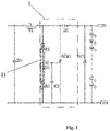
FIG. 1 is a circuit diagram of a preferred embodiment of a protective circuit for an output terminal capacitor of an LED driver provided by the present invention; and -
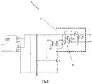
FIG. 2 is a circuit diagram of a preferred embodiment of an LED driver circuit provided by the present invention. - As illustrated in
FIG. 1 , the present invention provides aprotective circuit 1 for an output terminal capacitor of an LED driver. Theprotective circuit 1 is connected to two sides of an output terminal capacitor EC1, and comprises a switching element SCR1, avoltage dividing unit 11 and a one-way conduction unit D2. The switching element SCR1 is in parallel connection with the output terminal capacitor Etc1; the one-way conduction unit D2 is connected between the switching element SCR1 and the output terminal capacitor EC1; the switching element SCR1 is switched on when a voltage exceeds a threshold, so as to establish a short circuit between two ends of the output terminal capacitor EC1 and prevent an excessively large voltage from being applied to the output terminal capacitor EC1; and the one-way conduction unit D2 allows a current to flow across the output terminal capacitor EC1 from theprotective circuit 1 by a one-way conduction. Meanwhile, the one-way conduction unit D2 prevents the voltage released at the two ends of the output terminal capacitor EC1 from being applied to theprotective circuit 1 in an opposite direction, so as to protect the switching element SCR1 of theprotective circuit 1 from being damaged due to an excessively large voltage. An element indicated in the present invention refers to not only one independent electronic element, but also may refer to a circuit including a plurality of electronic elements. - In an embodiment, the switching element SCR1 is a thyristor. In other embodiments, the switching element SCR1 may be designed to be other elements or circuits with a threshold-voltage conduction function as needed.
- In an embodiment, the one-way conduction unit D2 is a diode. In other embodiments, the one-way conduction unit D2 may also be other elements or circuits capable of achieving one-way conduction.
- The
protective circuit 1 further comprises a threshold-voltage conduction unit ZD1. The threshold-voltage conduction unit ZD1 is connected between thevoltage dividing unit 11 and the switching element SCR1, and is switched on when the voltage at the two ends of theprotective circuit 1 exceeds a certain value. When a voltage after being divided by thevoltage dividing unit 11 exceeds a certain value, the threshold-voltage conduction unit ZD1 is switched on, and then the switching element SCR1 is switched on. In an embodiment, the threshold-voltage conduction unit ZD1 is a triode, specifically for example, a voltage stabilizing triode. Thus, the conduction condition can be achieved by adoption of different voltage stabilizing triodes as needed, which is convenient and simple. In other embodiments, the threshold-voltage conduction unit ZD1 may also be other elements or circuits capable of achieving the threshold-voltage conduction. - In an embodiment, the
voltage dividing unit 11 includes a first resistor R1 and a second resistor R2; and one end of the threshold-voltage conduction unit ZD1 is connected with the switching element SCR1, and another end of the threshold-voltage conduction unit ZD1 is connected between the first resistor R1 and the second resistor R2. In other embodiments, thevoltage dividing unit 11 may also be adjusted as needed. - The
protective circuit 1 further comprises a filter capacitor C2. One end of the filter capacitor C2 is connected between the threshold-voltage conduction unit ZD1 and the switching element SCR1, and another end of the filter capacitor C2 is connected to a connection point between the switching element SCR1 and the output terminal capacitor EC1. The filter capacitor C2 is used for preventing incorrect operations of theprotective circuit 1 caused by interference noise signals. - As shown in
FIG. 2 , theprotective circuit 1 for the output terminal capacitor of the LED driver provided in the invention is mostly applied to an output terminal of an LED driver circuit 3 provided with a buck topology circuit 2. In other embodiments, theprotective circuit 1 for the output terminal capacitor of the LED driver provided in the invention may also be applied in other topology circuits. - When the wirings operate normally, an output voltage is normal, and cannot break through the threshold-voltage conduction unit ZD1 after the voltage division of the first resistor R1 and the second resistor R2; the switching element SCR1 is in an off state as its voltage is lower than a trigger threshold; and the wirings may work properly.
- In an abnormal condition of the wirings (e.g., an output open-circuit state), the output voltage is raised; the output voltage after being divided by the first resistor R1 and the second resistor R2 breaks down the threshold-voltage conduction unit ZD1; and the switching element SCR1 is switched on as the voltage reaches the trigger threshold. Thus, no excessive voltage will be applied to the output terminal capacitor EC1. Meanwhile, the one-way conduction unit D2 prevents energy stored on the output terminal capacitor EC1 from being recharged into the switching element SCR1, so as to prevent the switching element SCR1 from being damaged by an excessively large instantaneous current due to the conduction short circuit.
- In another example, in another abnormal condition of the wirings of the circuit, when a triode Q1 of an LED driver circuit 3 is damaged with an emitter and a base being short-circuited, the output voltage after being divided by the first resistor R1 and the second resistor R2 breaks down the threshold-voltage conduction unit ZD1; the switching element SCR1 is switched on as the voltage reaches the trigger threshold; and as an input power is increased, a fuse RF1 of the LED driver circuit is open-circuited, and a mains input is disconnected, so that the output terminal capacitor EC1 can be protected. Meanwhile, the one-way conduction unit D2 prevents energy stored on the output terminal capacitor EC1 from being recharged into the switching element SCR1, so as to prevent the switching element SCR1 from being damaged by an excessively large instantaneous current due to the conduction short circuit.
- It should be noted that the embodiments of the present invention include preferred implementations and are not intended to limit the present invention in any form. Equivalent effective embodiments may be obtained by changing or modifying the technical content disclosed above by those skilled in the art. But any modification or equivalent change and modification made to the above embodiments, on the basis of the technical essence of the present invention without departing from the content of the technical proposal of the present invention, shall still fall within the scope of the technical proposal of the present invention.
Claims (8)
- A protective circuit for an output terminal capacitor of a light-emitting diode (LED) driver, with the protective circuit being connected to two sides of the output terminal capacitor, comprising a switching element, a voltage dividing unit and a one-way conduction unit, wherein the switching element is in parallel connection with the output terminal capacitor, the one-way conduction unit is connected between the switching element and the output terminal capacitor, the switching element is switched on when a voltage exceeds a threshold so as to establish a short circuit between two ends of the output terminal capacitor and prevent an excessively large voltage from being applied to the output terminal capacitor, and the one-way conduction unit allows a current to flow across the output terminal capacitor from the protective circuit by a one-way conduction.
- The protective circuit for the output terminal capacitor of the LED driver according to claim 1, wherein the protective circuit further comprises a threshold-voltage conduction unit, the threshold-voltage conduction unit is connected between the voltage dividing unit and the switching element and is switched on when a voltage at two ends of the protective circuit exceeds a certain value.
- The protective circuit for the output terminal capacitor of the LED driver according to claim 2, wherein the threshold-voltage conduction unit is a triode.
- The protective circuit for the output terminal capacitor of the LED driver according to claim 3, wherein the protective circuit further comprises a filter capacitor, one end of the filter capacitor is connected between the threshold-voltage conduction unit and the switching element, and another end of the filter capacitor is connected to a connection point of the switching element and the output terminal capacitor.
- The protective circuit for the output terminal capacitor of the LED driver according to claim 1, wherein the one-way conduction unit is a diode.
- The protective circuit for the output terminal capacitor of the LED driver according to claim 1, wherein the switching element is a thyristor.
- The protective circuit for the output terminal capacitor of the LED driver according to claim 6, wherein the protective circuit is applied to an output terminal of a buck topology circuit.
- The protective circuit for the output terminal capacitor of the LED driver according to claim 7, wherein the LED driver includes an LED driver circuit provided with the buck topology circuit.
Applications Claiming Priority (2)
| Application Number | Priority Date | Filing Date | Title |
|---|---|---|---|
| CN201410690465.4A CN104411051A (en) | 2014-11-25 | 2014-11-25 | LED drive output end capacitor protecting circuit |
| PCT/CN2015/000823 WO2016082302A1 (en) | 2014-11-25 | 2015-11-27 | Led driving output end capacitor protection circuit |
Publications (1)
| Publication Number | Publication Date |
|---|---|
| EP3211970A1 true EP3211970A1 (en) | 2017-08-30 |
Family
ID=52648631
Family Applications (1)
| Application Number | Title | Priority Date | Filing Date |
|---|---|---|---|
| EP15863014.5A Withdrawn EP3211970A1 (en) | 2014-11-25 | 2015-11-27 | Led driving output end capacitor protection circuit |
Country Status (4)
| Country | Link |
|---|---|
| US (1) | US10321538B2 (en) |
| EP (1) | EP3211970A1 (en) |
| CN (1) | CN104411051A (en) |
| WO (1) | WO2016082302A1 (en) |
Families Citing this family (2)
| Publication number | Priority date | Publication date | Assignee | Title |
|---|---|---|---|---|
| CN104411051A (en) * | 2014-11-25 | 2015-03-11 | 欧普照明股份有限公司 | LED drive output end capacitor protecting circuit |
| CN105162454B (en) * | 2015-10-12 | 2020-04-28 | 索尔思光电(成都)有限公司 | Optical module and signal output port thereof, and signal output port protection circuit |
Family Cites Families (7)
| Publication number | Priority date | Publication date | Assignee | Title |
|---|---|---|---|---|
| JP4943402B2 (en) * | 2008-10-09 | 2012-05-30 | シャープ株式会社 | LED drive circuit, LED illumination lamp, LED illumination device, and LED illumination system |
| US8710822B2 (en) * | 2008-10-13 | 2014-04-29 | Analog Devices, Inc. | Multi-state DC-DC converter having undirectional switches |
| CN202197098U (en) * | 2011-09-09 | 2012-04-18 | 深圳市澳磁电源科技有限公司 | Overvoltage protection circuit, LED driving power supply and LED lighting device |
| CN203352856U (en) * | 2013-06-24 | 2013-12-18 | 合肥龙多电子科技有限公司 | Capacitor step-down LED lighting power supply with open circuit protection |
| CN103683885B (en) * | 2013-12-12 | 2017-02-15 | 安伏(苏州)电子有限公司 | Device for preventing electric current backward flowing and output capacitor discharging |
| CN204859603U (en) * | 2014-11-25 | 2015-12-09 | 欧普照明股份有限公司 | A protection circuit for LED drive output capacitance |
| CN104411051A (en) * | 2014-11-25 | 2015-03-11 | 欧普照明股份有限公司 | LED drive output end capacitor protecting circuit |
-
2014
- 2014-11-25 CN CN201410690465.4A patent/CN104411051A/en active Pending
-
2015
- 2015-11-27 WO PCT/CN2015/000823 patent/WO2016082302A1/en not_active Ceased
- 2015-11-27 EP EP15863014.5A patent/EP3211970A1/en not_active Withdrawn
-
2017
- 2017-05-23 US US15/603,114 patent/US10321538B2/en active Active
Also Published As
| Publication number | Publication date |
|---|---|
| WO2016082302A1 (en) | 2016-06-02 |
| US10321538B2 (en) | 2019-06-11 |
| US20170257915A1 (en) | 2017-09-07 |
| CN104411051A (en) | 2015-03-11 |
Similar Documents
| Publication | Publication Date | Title |
|---|---|---|
| DE102008031029B4 (en) | Electronic component with a protective circuit for a light-emitting device | |
| US20150222109A1 (en) | Surge protection circuit | |
| US20140307351A1 (en) | Over-current Protection Circuit for Light Source Driving Module and Related Backlight Module | |
| CN104078925A (en) | Overvoltage protection device | |
| CN101820710A (en) | Open-circuit protection circuit | |
| US9462655B1 (en) | Circuit and method for monitoring functionality of an electronic surge suppressor | |
| US8686700B2 (en) | Boost type power converting apparatus with protection circuit | |
| CN207117164U (en) | The power protecting circuit and display device of a kind of display device | |
| CN203423477U (en) | Overvoltage protection circuit | |
| CN104578032A (en) | Over-voltage protector | |
| CN204733146U (en) | A kind of single-phase intelligent solid-state relay | |
| CN204697348U (en) | Backlight drive circuit and LED-backlit module | |
| CN107394749B (en) | Protective circuit | |
| JP6048164B2 (en) | Overcurrent protection circuit | |
| CN203618196U (en) | Anti-surge circuit and integrated circuit comprising same | |
| TWM566677U (en) | Vehicle lamp control circuit | |
| KR20170096424A (en) | Surge Protection Circuit | |
| CN105578645A (en) | Over-current protection method of LED driving power supply | |
| US10321538B2 (en) | Protective circuit for output terminal capacitor of light-emitting diode (LED) driver | |
| KR101687079B1 (en) | Power Supply Circuit For Light Emitting Diode Lighting Having Afterglow Eliminative Function | |
| CN202917966U (en) | MOS tube voltage reduction circuit, transformation circuit and liquid crystal television | |
| CN207853467U (en) | A kind of automobile-used throw load protection circuit based on reverse-connection preventing circuit | |
| CN204964723U (en) | High pressure alert circuit | |
| CN105846412B (en) | Surge protection device | |
| JP2015029397A (en) | Semiconductor power converter |
Legal Events
| Date | Code | Title | Description |
|---|---|---|---|
| STAA | Information on the status of an ep patent application or granted ep patent |
Free format text: STATUS: THE INTERNATIONAL PUBLICATION HAS BEEN MADE |
|
| PUAI | Public reference made under article 153(3) epc to a published international application that has entered the european phase |
Free format text: ORIGINAL CODE: 0009012 |
|
| STAA | Information on the status of an ep patent application or granted ep patent |
Free format text: STATUS: REQUEST FOR EXAMINATION WAS MADE |
|
| 17P | Request for examination filed |
Effective date: 20170526 |
|
| AK | Designated contracting states |
Kind code of ref document: A1 Designated state(s): AL AT BE BG CH CY CZ DE DK EE ES FI FR GB GR HR HU IE IS IT LI LT LU LV MC MK MT NL NO PL PT RO RS SE SI SK SM TR |
|
| AX | Request for extension of the european patent |
Extension state: BA ME |
|
| STAA | Information on the status of an ep patent application or granted ep patent |
Free format text: STATUS: THE APPLICATION HAS BEEN WITHDRAWN |
|
| 18W | Application withdrawn |
Effective date: 20170908 |