EP3211837A1 - Communication device, communication method, control method for communication device, and communication system - Google Patents
Communication device, communication method, control method for communication device, and communication system Download PDFInfo
- Publication number
- EP3211837A1 EP3211837A1 EP17159605.9A EP17159605A EP3211837A1 EP 3211837 A1 EP3211837 A1 EP 3211837A1 EP 17159605 A EP17159605 A EP 17159605A EP 3211837 A1 EP3211837 A1 EP 3211837A1
- Authority
- EP
- European Patent Office
- Prior art keywords
- communication
- wireless network
- communication device
- parameter
- devices
- Prior art date
- Legal status (The legal status is an assumption and is not a legal conclusion. Google has not performed a legal analysis and makes no representation as to the accuracy of the status listed.)
- Withdrawn
Links
- 238000004891 communication Methods 0.000 title claims abstract description 225
- 238000000034 method Methods 0.000 title claims description 23
- 230000004044 response Effects 0.000 claims description 18
- 238000010586 diagram Methods 0.000 description 13
- 230000005540 biological transmission Effects 0.000 description 7
- 239000000284 extract Substances 0.000 description 6
- 230000006870 function Effects 0.000 description 2
- 238000000605 extraction Methods 0.000 description 1
- 239000004973 liquid crystal related substance Substances 0.000 description 1
- 238000012986 modification Methods 0.000 description 1
- 230000004048 modification Effects 0.000 description 1
- 230000005236 sound signal Effects 0.000 description 1
Images



Classifications
-
- H—ELECTRICITY
- H04—ELECTRIC COMMUNICATION TECHNIQUE
- H04W—WIRELESS COMMUNICATION NETWORKS
- H04W8/00—Network data management
- H04W8/22—Processing or transfer of terminal data, e.g. status or physical capabilities
- H04W8/24—Transfer of terminal data
-
- H—ELECTRICITY
- H04—ELECTRIC COMMUNICATION TECHNIQUE
- H04W—WIRELESS COMMUNICATION NETWORKS
- H04W8/00—Network data management
- H04W8/22—Processing or transfer of terminal data, e.g. status or physical capabilities
- H04W8/24—Transfer of terminal data
- H04W8/245—Transfer of terminal data from a network towards a terminal
-
- H—ELECTRICITY
- H04—ELECTRIC COMMUNICATION TECHNIQUE
- H04W—WIRELESS COMMUNICATION NETWORKS
- H04W28/00—Network traffic management; Network resource management
- H04W28/16—Central resource management; Negotiation of resources or communication parameters, e.g. negotiating bandwidth or QoS [Quality of Service]
- H04W28/18—Negotiating wireless communication parameters
-
- H—ELECTRICITY
- H04—ELECTRIC COMMUNICATION TECHNIQUE
- H04W—WIRELESS COMMUNICATION NETWORKS
- H04W88/00—Devices specially adapted for wireless communication networks, e.g. terminals, base stations or access point devices
- H04W88/02—Terminal devices
-
- H—ELECTRICITY
- H04—ELECTRIC COMMUNICATION TECHNIQUE
- H04W—WIRELESS COMMUNICATION NETWORKS
- H04W84/00—Network topologies
- H04W84/18—Self-organising networks, e.g. ad-hoc networks or sensor networks
-
- H—ELECTRICITY
- H04—ELECTRIC COMMUNICATION TECHNIQUE
- H04W—WIRELESS COMMUNICATION NETWORKS
- H04W92/00—Interfaces specially adapted for wireless communication networks
- H04W92/16—Interfaces between hierarchically similar devices
- H04W92/18—Interfaces between hierarchically similar devices between terminal devices
Definitions
- the ad-hoc networks allow devices to directly communicate with one another via a wireless LAN without using an access point.
- ad-hoc networks there has also been a demand for a method for easily setting wireless communication parameters in devices.
- a wireless communication button of each of the devices is pressed to thereby configure an ad-hoc network for setting wireless communication parameters.
- each device operates as a master or a slave.
- a device that first establishes an ad-hoc network for setting wireless communication parameters is a master.
- the master device manages Media Access Control (MAC) addresses and the like of the other devices located within the same network as the network on which the master device exists.
- MAC Media Access Control
- the master device determines a pair of devices in which the wireless communication parameters are to be set on the basis of the device capability information transmitted from the slave devices, and instructs that the determined pair of devices perform parameter setting.
- the slave device or devices Upon receiving the instruction from the master device, the slave device or devices perform transmission and reception of the wireless communication parameters, and set the wireless communication parameters. Actual data communication can therefore be performed between the devices in which the wireless communication parameters have been set.
- the wireless communication parameters include a communication channel, a network identifier (SSID), an encryption method, an encryption key, an authentication method, and an authentication key.
- Both the master and the slave periodically send a notification of their presence (master announcement and slave announcement).
- Fig. 3 is a system configuration diagram of a system according to a first embodiment of the present invention.
- Each of a digital still camera (hereinafter referred to as a "DSC") 301, a printer (hereinafter referred to as a "PRN”) 302, and a digital video camera (hereinafter referred to as a "DVC”) 303 has a wireless communication function.
- a wireless communication button of each of the devices is pressed to thereby establish an ad-hoc network for setting the wireless communication parameters.
- a display unit 106 is a block for displaying information to a user, such as a liquid crystal display (LCD), a light-emitting diode (LED) display, or an audio display.
- a display processor 107 performs display control of the display unit 106.
- the display unit 106 is operated with the operation unit 110 to select an option from the information displayed on the display unit 106. That is, the display unit 106 and the operation unit 110 constitute a user interface.
- a memory card interface (hereinafter referred to as an "I/F") 108 is an interface to which a memory card 109 is connected.
- a universal serial bus (USB) I/F 112 is an interface for connecting to an external device using a USB.
- An audio I/F 114 is an interface for connecting an audio signal to an external device.
- Fig. 1 The functional blocks illustrated in Fig. 1 are processed under the control of the CPU 115. Operation programs described below with reference to Figs. 9 and 10 are stored in a ROM 116, a flash ROM 113, or the memory card 109, and the CPU 115 performs processing according to the programs.
- RAM random access memory
- flash ROM 113 flash ROM
- memory card 109 memory card
- the flash ROM 113 stores a device capability table (see Figs. 7 and 8 ).
- the device capability table is used to select a communication device.
- a print engine 202 is a functional block for actually printing an image on a sheet of paper, and is processed by a print processor 203.
- the print engine 202 is an ink-jet print engine for ejecting ink droplets onto a recording medium such as a sheet of recording paper using thermal energy, although any other print engine may be used.
- a memory card I/F 208 is an interface to which a memory card 209 is connected.
- a USB I/F 212 is an interface for connecting to an external device using a USB.
- An Ether I/F 214 is an interface for connecting to an external device via an Ethernet connection.
- the functional blocks illustrated in Fig. 2 are processed under the control of the CPU 215.
- the operation programs described below with reference to Figs. 9 and 10 are stored in a ROM 216, a flash ROM 213, or the memory card 209, and the CPU 215 performs processing according to the programs.
- Data processed by the CPU 215 is written to or read from a RAM 217, the flash ROM 213, or the memory card 209.
- the flash ROM 213 stores a device capability table (see Figs. 7 and 8 ).
- the device capability table is used to select a communication device.
- Fig. 5 is a sequence diagram of the first embodiment.
- the PRN 302 exists as a master device on a network.
- the master device waits for a predetermined time for other devices to participate in the network, and selects a pair of devices in which the communication parameters are to be set among the participating devices.
- the DVC 303 transmits (501) a "Who is Master?" signal via broadcast to search for the master device.
- broadcast means transmission of data to a large number of unspecified parties.
- the PRN 302 Upon receiving the "Who is Master?" signal, the PRN 302 transmits (502) an "I am Master” signal to the DVC 303 via unicast to announce that the PRN 302 is the master device.
- the term unicast means transmission of data to a specified party.
- the PRN 302 Upon receiving the "Who is Master?" signal, the PRN 302 transmits (505) an "I am Master” signal to the DSC 301 via unicast to announce that the PRN 302 is the master device.
- the DSC 301 Upon receiving the "I am Master” signal, the DSC 301 transmits (506) an "I am slave” signal to the PRN 302, which is the master device, via unicast to announce that the DSC 301 is to become a slave device.
- the PRN 302 which is the master device, selects a pair of devices in which the communication parameters are to be set.
- the PRN 302 transmits (507) a "capability request" as a request for transmission of the device capabilities via broadcast to obtain the capabilities of all the devices located within the network.
- the "capability request” may be transmitted via unicast or via multicast that allows simultaneous transmission to a plurality of specified devices.
- the slave devices namely, the DSC 301 and the DVC 303, transmit (508 and 509) their device capabilities to the PRN 302 as “capability responses”.
- the PRN 302 Upon receiving the "capability responses", the PRN 302 stores the device capabilities of those devices in the device capability table stored in the flash ROM 213.
- the device capability table and a method for selecting a pair of devices in which the communication parameters are to be set using the device capability table will be described with reference to Fig. 7 .
- the device capability table stores a Media Access Control (MAC) address, a device attribute, a device category, and a communication parameter service attribute of each device.
- MAC Media Access Control
- the device attribute indicates the type of each device (such as a printer or a still camera), and the device category indicates an input device or an output device.
- the communication parameter service attribute indicates whether each device has a communication-parameter-providing capability or a communication-parameter-receiving capability.
- the device capabilities of the PRN 302, which is the master device, are described in Index 1.
- the device capabilities of the DVC 303 are described in Index 2
- the device capabilities of the DSC 301 are described in Index 3.
- the PRN 302 which is the master device, refers to the communication parameter service attributes, and extracts a pair of devices having a "parameter provider-receiver" relationship.
- the pair of Index 1 and Index 2 and the pair of Index 1 and Index 3 are extracted as possible pairs. That is, the pair of the PRN 302 and the DVC 303 and the pair of the PRN 302 and the DSC 301 are extracted.
- the PRN 302 further refers to the device attributes to determine one pair. Specifically, the PRN 302 determines the final pair based on a preferential pair pattern that is stored in advance in each device. It is assumed here that a pair of a printer and a still camera is stored as the preferential pair pattern. Accordingly, the PRN 302 selects the pair of Index 1 and Index 3 as the final pair.
- the preferential pair pattern is set in advance with respect to the device attributes. Any pair of devices other than a pair of a still camera and a printer, such as a pair of a video camera and a display or a pair of a DVD player and a TV set, may be set as the preferential pair pattern.
- the PRN 302 transmits (510) a cancellation signal for canceling the setting of the wireless communication parameters to the DVC 303 that falls outside the selected pair.
- the DVC 303 Upon receiving the cancellation signal, the DVC 303 notifies (511) the PRN 302 of the acceptance of the cancellation.
- the PRN 302 transmits (512) a communication-parameter-receiver-request signal to the DSC 301 that is selected as the communication partner.
- the communication-parameter-receiver-request signal includes the MAC address of the PRN 302, which is the communication parameter provider.
- the DSC 301 Upon receiving the communication-parameter-receiver-request signal, the DSC 301 receives the MAC address of the PRN 302, and transmits (513) a communication-parameter-receiver-response signal to the PRN 302, which is the communication parameter provider.
- the communication parameters are transmitted from the communication parameter provider, i.e., the PRN 302, to the communication parameter receiver, i.e., the DSC 301, and the same parameters are set (514) in the PRN 302 and the DSC 301. Therefore, wireless communication can be performed between both devices.
- the communication parameter provider i.e., the PRN 302
- the communication parameter receiver i.e., the DSC 301
- the master device waits for a predetermined time for devices that send a request to participate in the network.
- the master device transmits a capability request to a participating slave device (step 901 shown in Fig. 9 ), and sets a response-waiting timer (step 902).
- the slave device waits until a capability request is received from the master device (step 1001 shown in Fig. 10 ). Upon receiving the capability request (Yes in step 1001), the slave device transmits its device capabilities as a capability response (step 1002).
- the master device If the master device receives a capability response from the slave device before the response-waiting timer has timed out ("NO” in step 903 and "YES” in step 904), the master device stores the device capabilities included in the response in the device capability table (see Fig. 7 ) (step 905).
- the master device repeatedly performs the processing of steps 903 through 905 until the response-waiting timer has timed out, and stores the received device capabilities of the slave devices in the device capability table.
- the master device refers to the communication parameter service attributes in the device capability table, and extracts a device pair having a "parameter provider-receiver” relationship (step 906).
- the master device transmits a cancellation signal for canceling the parameter setting to the slave devices located within the network (step 914).
- step 907 If only one device pair is found ("YES” in step 907 and "YES” in step 908), the process proceeds to step 912. If a plurality of device pairs are found ("NO” in step 908), the master device further refers to the device categories, and extracts a device pair having an "IN-OUT" relationship (step 909).
- the possible device pairs are narrowed down by determining whether each of the device pairs is a pair of input and output devices. Therefore, the possibility of setting the communication parameters in an unintended pair of devices can be reduced.
- step 910 If the pairs are narrowed down to select one pair ("YES" in step 910), the selected pair of devices is determined as the desired pair, and the process proceeds to step 912. As a result of the narrowing down, if a plurality of device pairs are still found ("NO” in step 910), a preferential pair pattern that is stored in advance is checked. If any pair matching the preferential pair pattern is found in the pairs, the matched pair is determined as the desired pair (step 911). Then, the process proceeds to step 912.
- the master device transmits a cancellation signal to an unselected device.
- the master device causes the selected pair of devices to perform communication for setting the parameters (step 913). Specifically, the master device notifies the communication parameter provider that it is to become the provider of the communication parameters, and also notifies the communication parameter provider of the MAC address of the communication parameter receiver. The master device notifies the communication parameter receiver that it is to become the receiver of the communication parameters, and also notifies the communication parameter receiver of the MAC address of the communication parameter provider. If the master device itself is the communication parameter provider or receiver, the master device may send the notifications to the other device.
- the slave device transmits a capability response (step 1002), and then waits for an incoming message from the master device (step 1003). Upon receiving a message ("YES" in step 1003), the slave device performs different processing depending on the content of the received message (step 1004).
- the slave device transmits the acceptance of the cancellation to the master device (step 1005), and terminates the wireless communication (step 1006).
- a device that has received the cancellation signal displays on the display unit (106 or 206 shown in Fig. 1 or 2 ) that the setting of the wireless communication parameters has been canceled. Thus, the user can understand that the wireless communication has been canceled.
- the network for setting the communication parameters may be automatically reconfigured. In this case, even if the parameters are to be set in an unintended pair of devices, the setting can be stopped, and the parameters can be set in a pair of devices that is not selected. Further, the user does not need to perform the operation again, thus increasing user convenience.
- the slave device stores the MAC address of the communication parameter provider included in the request, and transmits a communication-parameter-receiver response to the master device (step 1007).
- the slave device stores the MAC address of the communication parameter receiver included in the request, and transmits a communication-parameter-provider response to the master device (step 1009).
- the communication parameters are set in the determined communication parameter provider and communication parameter receiver (step 1008), and wireless communication can therefore be performed using the set parameters.
- the preferential selection processing allows one pair to be selected.
- An unselected device is notified of cancellation of the parameter setting, thus preventing the communication parameters from being set in an unintended pair of devices. Further, since the master device can automatically select a pair of devices and notify cancellation, wireless communication can efficiently be established without performing a user's operation.
- the preferential selection (step 911 shown in Fig. 9 ) is performed using the device attributes. If it is difficult to determine one device pair, a pair of devices that are stored in upper rows of the table may be selected, or a pair of devices may be randomly selected by generating random numbers.
- the preferential selection processing of step 911 is performed after possible pairs are narrowed down by performing the processing of steps 907 and 909.
- Fig. 4 is a system configuration diagram of a system according to a second embodiment of the present invention.
- a network shown in Fig. 4 one digital camera (a DSC 301) and two printers (PRNs 302 and 401) exist.
- the block diagrams of those devices are similar to those of Figs. 1 and 2 , and a description thereof is thus omitted.
- Fig. 6 is a sequence diagram of the second embodiment.
- the DSC 301 exists as a master device on a network.
- the master device waits for a predetermined time for other devices to participate in the network, and selects a pair of devices in which the communication parameters are to be set among the participating devices.
- the PRN 401 transmits (601) a "Who is Master?" signal via broadcast to search for the master device.
- the DSC 301 Upon receiving the "Who is Master?" signal, the DSC 301 transmits (602) an "I am Master” signal to the PRN 401 via unicast to announce that the DSC 301 is the master device.
- the PRN 401 Upon receiving the "I am Master” signal, the PRN 401 transmits (603) an "I am slave” signal to the DSC 301, which is the master device, via unicast to announce that the PRN 401 is to become a slave device.
- the PRN 302 also transmits (604) a "Who is Master?" signal via broadcast to search for the master device.
- the DSC 301 Upon receiving the "Who is Master?" signal, the DSC 301 transmits (605) an "I am Master” signal to the PRN 302 via unicast to announce that the DSC 301 is the master device.
- communication devices have been discussed in the context of a digital still camera, a printer, and a digital video camera.
- the communication devices may also include devices such as PCs, copying machines, and mobile phones.
Landscapes
- Engineering & Computer Science (AREA)
- Computer Networks & Wireless Communication (AREA)
- Signal Processing (AREA)
- Databases & Information Systems (AREA)
- Quality & Reliability (AREA)
- Mobile Radio Communication Systems (AREA)
- Small-Scale Networks (AREA)
- Telephonic Communication Services (AREA)
Abstract
Description
- The present invention relates to communication devices for performing communication parameter setting.
- When communication is to be performed between devices using IEEE 802.11 wireless local area networks (LANs), wireless communication parameters such as a communication channel, a network identifier called a service set identifier (SSID), an encryption method, an encryption key, an authentication method, and an authentication key are set in the devices. Such communication parameters are generally set using user interfaces of the devices. However, the setting operation is time consuming. In particular, it is difficult for devices other than personal computers (PCs), such as digital cameras and printers, to input character strings such as a network identifier and an encryption key.
- Recently, systems for performing communication over so-called ad-hoc networks have been realized. The ad-hoc networks allow devices to directly communicate with one another via a wireless LAN without using an access point. In the ad-hoc networks, there has also been a demand for a method for easily setting wireless communication parameters in devices.
-
U.S. Patent Laid-Open No. 2006-200564 (corresponding to Japanese Patent Laid-Open No.2004-328289 - In
U.S. Patent Laid-Open No. 2006-200564 , however, if a response to a request for establishing a communication channel is issued from a plurality of devices, an operation for interrupting the establishment of the communication channel or an operation for causing a user to select a communication partner is performed. - Therefore, if an unintended device exists when a communication channel is to be established, the establishment of communication is performed again from the beginning, or, otherwise, a user needs to select a communication partner.
- In view of the above-described problems, the present invention provides a technique for setting communication parameters in devices when devices other than the devices in which the communication parameters are to be set exist on a network.
- The present invention in its first aspect provides a communication device as specified in
claims 1 to 5. - The present invention in its second aspect provides a method as specified in
claims 6 and 7. - The present invention in its third aspect provides a program as specified in
claim 8. - Further features of the present invention will become apparent from the following description of exemplary embodiments with reference to the attached drawings.
-
-
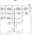
Fig. 1 is a block diagram of a digital camera and a digital video camera. -
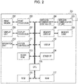
Fig. 2 is a block diagram of a printer. -
Fig. 3 is a system configuration diagram of a system according to a first embodiment of the present invention. -
Fig. 4 is a system configuration diagram of a system according to a second embodiment of the present invention. -
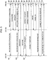
Fig. 5 is a sequence diagram of the first embodiment. -
Fig. 6 is a sequence diagram of the second embodiment. -
Fig. 7 is a device capability table of the first embodiment. -
Fig. 8 is a device capability table of the second embodiment. -
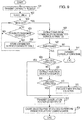
Fig. 9 is a flowchart showing the operation of a master device according to the first and second embodiments. -
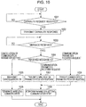
Fig. 10 is a flowchart showing the operation of a slave device according to the first and second embodiments. - Exemplary embodiments of the present invention will be described in detail with reference to the drawings.
- In the exemplary embodiments, a process for configuring an ad-hoc network that allows direct wireless communication between devices will be described.
- A wireless communication button of each of the devices is pressed to thereby configure an ad-hoc network for setting wireless communication parameters. In the ad-hoc network of the exemplary embodiments, each device operates as a master or a slave.
- In the exemplary embodiments, a device that first establishes an ad-hoc network for setting wireless communication parameters is a master. The master device manages Media Access Control (MAC) addresses and the like of the other devices located within the same network as the network on which the master device exists.
- The master device transmits a "capability request" to the slave devices as a request for transmission of the device capabilities, and the slave devices return their device capabilities as a "capability response" according to the request. The "capability response" includes an MAC address, a device attribute (such as a printer or a still camera), a device category (an input device or an output device), and a communication parameter service attribute (a parameter receiver or a parameter provider).
- The master device determines a pair of devices in which the wireless communication parameters are to be set on the basis of the device capability information transmitted from the slave devices, and instructs that the determined pair of devices perform parameter setting. Upon receiving the instruction from the master device, the slave device or devices perform transmission and reception of the wireless communication parameters, and set the wireless communication parameters. Actual data communication can therefore be performed between the devices in which the wireless communication parameters have been set. The wireless communication parameters include a communication channel, a network identifier (SSID), an encryption method, an encryption key, an authentication method, and an authentication key.
- Both the master and the slave periodically send a notification of their presence (master announcement and slave announcement).
-
Fig. 3 is a system configuration diagram of a system according to a first embodiment of the present invention. Each of a digital still camera (hereinafter referred to as a "DSC") 301, a printer (hereinafter referred to as a "PRN") 302, and a digital video camera (hereinafter referred to as a "DVC") 303 has a wireless communication function. A wireless communication button of each of the devices is pressed to thereby establish an ad-hoc network for setting the wireless communication parameters. - It is assumed here that wireless communication is performed between the DSC 301 and the PRN 302 to print image data stored in the DSC 301 using the PRN 302. The first embodiment will be described with respect to a case in which the
DVC 303, which is not intended by the user, exists on the same network as the DSC 301 and the PRN 302 when the wireless communication buttons of the DSC 301 and the PRN 302 are pressed to start wireless communication. -
Fig. 1 is a functional block diagram of theDSC 301 according to the first embodiment. The DVC 303 has a similar functional structure to that of theDSC 301. - An
operation unit 110 is connected to a central processing unit (CPU) 115 via asystem controller 111. Theoperation unit 110 includes various keys such as a shutter switch and a wireless communication button. - An image-capturing
unit 102 is a block for capturing an image when a shutter is released, and is processed by an image-capturingprocessor 103. - A
display unit 106 is a block for displaying information to a user, such as a liquid crystal display (LCD), a light-emitting diode (LED) display, or an audio display. Adisplay processor 107 performs display control of thedisplay unit 106. Thedisplay unit 106 is operated with theoperation unit 110 to select an option from the information displayed on thedisplay unit 106. That is, thedisplay unit 106 and theoperation unit 110 constitute a user interface. - A wireless
communication RF unit 105 and awireless communication controller 104 constitute a wireless communication interface. The wirelesscommunication RF unit 105 includes a hardware block for converting an analog signal received from an antenna into a digital signal and converting a digital signal into an analog signal to be transmitted from the antenna. Thewireless communication controller 104 is formed of hardware for processing a MAC layer responsible for controlling communication and firmware for driving the MAC layer. Thewireless communication controller 104 includes a built-in flash read-only memory (ROM) for storing the MAC addresses and the like. - A memory card interface (hereinafter referred to as an "I/F") 108 is an interface to which a
memory card 109 is connected. A universal serial bus (USB) I/F 112 is an interface for connecting to an external device using a USB. An audio I/F 114 is an interface for connecting an audio signal to an external device. - The functional blocks illustrated in
Fig. 1 are processed under the control of theCPU 115. Operation programs described below with reference toFigs. 9 and10 are stored in aROM 116, aflash ROM 113, or thememory card 109, and theCPU 115 performs processing according to the programs. - Data processed by the
CPU 115 is written to or read from a random access memory (RAM) 117, theflash ROM 113, or thememory card 109. It is to be noted that captured image data is stored in thememory card 109. - The
flash ROM 113 stores a device capability table (seeFigs. 7 and 8 ). The device capability table is used to select a communication device. -
Fig. 2 is a functional block diagram of thePRN 302 according to the first embodiment. - An
operation unit 210 is connected to aCPU 215 via asystem controller 211. - A
print engine 202 is a functional block for actually printing an image on a sheet of paper, and is processed by aprint processor 203. In the first embodiment, theprint engine 202 is an ink-jet print engine for ejecting ink droplets onto a recording medium such as a sheet of recording paper using thermal energy, although any other print engine may be used. - A
display unit 206 is a block for displaying information to a user, such as an LCD display, an LED display, or an audio display. Adisplay processor 207 performs display control of thedisplay unit 206. An option is selected from the information displayed on thedisplay unit 206 using theoperation unit 210. That is, thedisplay unit 206 and theoperation unit 210 serve as a user I/F of thePRN 302 in the first embodiment. - A memory card I/
F 208 is an interface to which amemory card 209 is connected. A USB I/F 212 is an interface for connecting to an external device using a USB. An Ether I/F 214 is an interface for connecting to an external device via an Ethernet connection. - A wireless
communication RF unit 205 and awireless communication controller 204 constitute a wireless interface. The wirelesscommunication RF unit 205 includes a hardware block for converting an analog signal received from an antenna into a digital signal and converting digital information into an analog signal to be transmitted from the antenna. Thewireless communication controller 204 is formed of hardware for processing, a MAC layer responsible for controlling communication, and firmware for driving the MAC layer. Thewireless communication controller 204 includes a built-in flash ROM for storing the MAC addresses and the like. - The functional blocks illustrated in
Fig. 2 are processed under the control of theCPU 215. The operation programs described below with reference toFigs. 9 and10 are stored in aROM 216, aflash ROM 213, or thememory card 209, and theCPU 215 performs processing according to the programs. Data processed by theCPU 215 is written to or read from aRAM 217, theflash ROM 213, or thememory card 209. - The
flash ROM 213 stores a device capability table (seeFigs. 7 and 8 ). The device capability table is used to select a communication device. -
Fig. 5 is a sequence diagram of the first embodiment. - First, it is assumed that the
PRN 302 exists as a master device on a network. - The master device waits for a predetermined time for other devices to participate in the network, and selects a pair of devices in which the communication parameters are to be set among the participating devices.
- When the wireless communication button of the
DVC 303 is pressed, theDVC 303 transmits (501) a "Who is Master?" signal via broadcast to search for the master device. The term broadcast means transmission of data to a large number of unspecified parties. - Upon receiving the "Who is Master?" signal, the
PRN 302 transmits (502) an "I am Master" signal to theDVC 303 via unicast to announce that thePRN 302 is the master device. The term unicast means transmission of data to a specified party. - Upon receiving the "I am Master" signal, the
DVC 303 transmits (503) an "I am slave" signal to thePRN 302, which is the master device, via unicast to announce that theDVC 303 is to become a slave device. - Then, when the wireless communication button of the
DSC 301 is pressed, theDSC 301 also transmits (504) a "Who is Master?" signal via broadcast to search for the master device. - Upon receiving the "Who is Master?" signal, the
PRN 302 transmits (505) an "I am Master" signal to theDSC 301 via unicast to announce that thePRN 302 is the master device. - Upon receiving the "I am Master" signal, the
DSC 301 transmits (506) an "I am slave" signal to thePRN 302, which is the master device, via unicast to announce that theDSC 301 is to become a slave device. - When the waiting time for new network participating devices has expired, the
PRN 302, which is the master device, selects a pair of devices in which the communication parameters are to be set. - The
PRN 302 transmits (507) a "capability request" as a request for transmission of the device capabilities via broadcast to obtain the capabilities of all the devices located within the network. The "capability request" may be transmitted via unicast or via multicast that allows simultaneous transmission to a plurality of specified devices. - Upon receiving the "capability request", the slave devices, namely, the
DSC 301 and theDVC 303, transmit (508 and 509) their device capabilities to thePRN 302 as "capability responses". - Upon receiving the "capability responses", the
PRN 302 stores the device capabilities of those devices in the device capability table stored in theflash ROM 213. The device capability table and a method for selecting a pair of devices in which the communication parameters are to be set using the device capability table will be described with reference toFig. 7 . - The device capability table stores a Media Access Control (MAC) address, a device attribute, a device category, and a communication parameter service attribute of each device.
- The device attribute indicates the type of each device (such as a printer or a still camera), and the device category indicates an input device or an output device. The communication parameter service attribute indicates whether each device has a communication-parameter-providing capability or a communication-parameter-receiving capability.
- The device capabilities of the
PRN 302, which is the master device, are described inIndex 1. The device capabilities of theDVC 303 are described inIndex 2, and the device capabilities of theDSC 301 are described inIndex 3. - First, the
PRN 302, which is the master device, refers to the communication parameter service attributes, and extracts a pair of devices having a "parameter provider-receiver" relationship. In this case, the pair ofIndex 1 andIndex 2 and the pair ofIndex 1 andIndex 3 are extracted as possible pairs. That is, the pair of thePRN 302 and theDVC 303 and the pair of thePRN 302 and theDSC 301 are extracted. - Since the above-described processing does not allow the pairs to be narrowed down until one pair is left, the
PRN 302 then refers to the device categories, and extracts a pair of input and output devices, i.e., a pair of devices having an "IN-OUT" relationship. In this case, the pair ofIndex 1 andIndex 2 and the pair ofIndex 1 andIndex 3 are extracted. - If the above-described determination processing does not allow one pair to be determined, the
PRN 302 further refers to the device attributes to determine one pair. Specifically, thePRN 302 determines the final pair based on a preferential pair pattern that is stored in advance in each device. It is assumed here that a pair of a printer and a still camera is stored as the preferential pair pattern. Accordingly, thePRN 302 selects the pair ofIndex 1 andIndex 3 as the final pair. - The preferential pair pattern is set in advance with respect to the device attributes. Any pair of devices other than a pair of a still camera and a printer, such as a pair of a video camera and a display or a pair of a DVD player and a TV set, may be set as the preferential pair pattern.
- Referring back to
Fig. 5 , upon determining the pair of devices in which the communication parameters are to be set, thePRN 302 transmits (510) a cancellation signal for canceling the setting of the wireless communication parameters to theDVC 303 that falls outside the selected pair. Upon receiving the cancellation signal, theDVC 303 notifies (511) thePRN 302 of the acceptance of the cancellation. - The
PRN 302 transmits (512) a communication-parameter-receiver-request signal to theDSC 301 that is selected as the communication partner. The communication-parameter-receiver-request signal includes the MAC address of thePRN 302, which is the communication parameter provider. Upon receiving the communication-parameter-receiver-request signal, theDSC 301 receives the MAC address of thePRN 302, and transmits (513) a communication-parameter-receiver-response signal to thePRN 302, which is the communication parameter provider. - Then, the communication parameters are transmitted from the communication parameter provider, i.e., the
PRN 302, to the communication parameter receiver, i.e., theDSC 301, and the same parameters are set (514) in thePRN 302 and theDSC 301. Therefore, wireless communication can be performed between both devices. - The operation flows of a master device and a slave device for determining a pair of devices in which the communication parameters are to be set will be described with
Figs. 9 and10 , respectively. - The master device waits for a predetermined time for devices that send a request to participate in the network. When the predetermined time has elapsed, the master device transmits a capability request to a participating slave device (step 901 shown in
Fig. 9 ), and sets a response-waiting timer (step 902). - The slave device waits until a capability request is received from the master device (
step 1001 shown inFig. 10 ). Upon receiving the capability request (Yes in step 1001), the slave device transmits its device capabilities as a capability response (step 1002). - If the master device receives a capability response from the slave device before the response-waiting timer has timed out ("NO" in
step 903 and "YES" in step 904), the master device stores the device capabilities included in the response in the device capability table (seeFig. 7 ) (step 905). - The master device repeatedly performs the processing of
steps 903 through 905 until the response-waiting timer has timed out, and stores the received device capabilities of the slave devices in the device capability table. - If the response-waiting timer has timed out ("YES" in step 903), the master device refers to the communication parameter service attributes in the device capability table, and extracts a device pair having a "parameter provider-receiver" relationship (step 906).
- As a result of the extraction, if no device pair is found ("NO" in step 907), the master device transmits a cancellation signal for canceling the parameter setting to the slave devices located within the network (step 914).
- If only one device pair is found ("YES" in
step 907 and "YES" in step 908), the process proceeds to step 912. If a plurality of device pairs are found ("NO" in step 908), the master device further refers to the device categories, and extracts a device pair having an "IN-OUT" relationship (step 909). - In this way, among the pairs of devices between which communication parameters can be exchanged, the possible device pairs are narrowed down by determining whether each of the device pairs is a pair of input and output devices. Therefore, the possibility of setting the communication parameters in an unintended pair of devices can be reduced.
- If the pairs are narrowed down to select one pair ("YES" in step 910), the selected pair of devices is determined as the desired pair, and the process proceeds to step 912. As a result of the narrowing down, if a plurality of device pairs are still found ("NO" in step 910), a preferential pair pattern that is stored in advance is checked. If any pair matching the preferential pair pattern is found in the pairs, the matched pair is determined as the desired pair (step 911). Then, the process proceeds to step 912.
- In
step 912, the master device transmits a cancellation signal to an unselected device. The master device causes the selected pair of devices to perform communication for setting the parameters (step 913). Specifically, the master device notifies the communication parameter provider that it is to become the provider of the communication parameters, and also notifies the communication parameter provider of the MAC address of the communication parameter receiver. The master device notifies the communication parameter receiver that it is to become the receiver of the communication parameters, and also notifies the communication parameter receiver of the MAC address of the communication parameter provider. If the master device itself is the communication parameter provider or receiver, the master device may send the notifications to the other device. - The slave device transmits a capability response (step 1002), and then waits for an incoming message from the master device (step 1003). Upon receiving a message ("YES" in step 1003), the slave device performs different processing depending on the content of the received message (step 1004).
- If the received message is a message for canceling the setting of the wireless communication parameters, the slave device transmits the acceptance of the cancellation to the master device (step 1005), and terminates the wireless communication (step 1006). A device that has received the cancellation signal displays on the display unit (106 or 206 shown in
Fig. 1 or2 ) that the setting of the wireless communication parameters has been canceled. Thus, the user can understand that the wireless communication has been canceled. - After the cancellation signal has been received, the network for setting the communication parameters may be automatically reconfigured. In this case, even if the parameters are to be set in an unintended pair of devices, the setting can be stopped, and the parameters can be set in a pair of devices that is not selected. Further, the user does not need to perform the operation again, thus increasing user convenience.
- If the received message is a communication-parameter-receiver request, the slave device stores the MAC address of the communication parameter provider included in the request, and transmits a communication-parameter-receiver response to the master device (step 1007).
- If the received message is a communication-parameter-provider request, the slave device stores the MAC address of the communication parameter receiver included in the request, and transmits a communication-parameter-provider response to the master device (step 1009).
- Then, the communication parameters are set in the determined communication parameter provider and communication parameter receiver (step 1008), and wireless communication can therefore be performed using the set parameters.
- According to the first embodiment, even if a plurality of devices exist on the same network when communication parameters are to be set, a desired pair of devices as communication partners can be selected, and the communication parameters are set in the selected pair of devices. In particular, if pairs extracted by referring to the communication parameter service attributes and the device categories are not narrowed down until one pair is left, the preferential selection processing allows one pair to be selected.
- An unselected device is notified of cancellation of the parameter setting, thus preventing the communication parameters from being set in an unintended pair of devices. Further, since the master device can automatically select a pair of devices and notify cancellation, wireless communication can efficiently be established without performing a user's operation.
- In the foregoing description, the preferential selection (step 911 shown in
Fig. 9 ) is performed using the device attributes. If it is difficult to determine one device pair, a pair of devices that are stored in upper rows of the table may be selected, or a pair of devices may be randomly selected by generating random numbers. - In
Fig. 9 , the preferential selection processing ofstep 911 is performed after possible pairs are narrowed down by performing the processing ofsteps steps step 912 is performed. By performing this processing, a desired pair can efficiently be determined in a case where a pair of normally used devices is known (such as a DSC and a PRN). -
Fig. 4 is a system configuration diagram of a system according to a second embodiment of the present invention. In a network shown inFig. 4 , one digital camera (a DSC 301) and two printers (PRNs 302 and 401) exist. The block diagrams of those devices are similar to those ofFigs. 1 and2 , and a description thereof is thus omitted. - It is assumed here that wireless communication is performed between the
DSC 301 and thePRN 302 to print image data stored in theDSC 301 using thePRN 302. The second embodiment will be described with respect to a case in which thePRN 401, which is not intended by the user, exists on the same network as theDSC 301 and thePRN 302 when the wireless communication buttons of theDSC 301 and thePRN 302 are pressed. -
Fig. 6 is a sequence diagram of the second embodiment. - First, it is assumed that the
DSC 301 exists as a master device on a network. The master device waits for a predetermined time for other devices to participate in the network, and selects a pair of devices in which the communication parameters are to be set among the participating devices. - When the wireless communication button of the
PRN 401 is pressed, thePRN 401 transmits (601) a "Who is Master?" signal via broadcast to search for the master device. - Upon receiving the "Who is Master?" signal, the
DSC 301 transmits (602) an "I am Master" signal to thePRN 401 via unicast to announce that theDSC 301 is the master device. - Upon receiving the "I am Master" signal, the
PRN 401 transmits (603) an "I am slave" signal to theDSC 301, which is the master device, via unicast to announce that thePRN 401 is to become a slave device. - Then, when the wireless communication button of the
PRN 302 is pressed, thePRN 302 also transmits (604) a "Who is Master?" signal via broadcast to search for the master device. - Upon receiving the "Who is Master?" signal, the
DSC 301 transmits (605) an "I am Master" signal to thePRN 302 via unicast to announce that theDSC 301 is the master device. - Upon receiving the "I am Master" signal, the
PRN 302 transmits (606) an "I am slave" signal to theDSC 301, which is the master device, via unicast to announce that thePRN 302 is to become a slave device. - When the waiting time for new network participating devices has expired, the
DSC 301, which is the master device, selects a pair of devices in which the communication parameters are to be set. - The
DSC 301 transmits (607) a "capability request" as a request for transmission of the device capabilities via broadcast to obtain the capabilities of all the devices located within the network. The "capability request" may be transmitted via unicast or multicast. - Upon receiving the "capability request", the slave devices, namely, the
PRN 302 and thePRN 401, transmit (608 and 609) their device capabilities to theDSC 301, which is the master device, as "capability responses". - Upon receiving the "capability responses", the
DSC 301 stores the device capabilities of those devices, such as the device attributes, in the device capability table stored in theflash ROM 113. The device capability table and a method for selecting a pair of devices in which the communication parameters are to be set using the device capability table will be described with reference toFig. 8 . - The device capabilities of the
DSC 301, which is the master device, are described inIndex 1. The device capabilities of thePRN 401 are described inIndex 2. The device capabilities of thePRN 302 are described inIndex 3. ThePRN 302 has both communication-parameter-providing and receiving capacities. - First, the
DSC 301, which is the master device, refers to the communication parameter service attributes, and extracts a pair of devices having a "parameter provider-receiver" relationship. In this case, the pair ofIndex 1 andIndex 3 and the pair ofIndex 2 andIndex 3 are extracted as possible communication pairs. That is, the pair of theDSC 301 and thePRN 302, and the pair of thePRN 401 and thePRN 302 are extracted. - Then, the
DSC 301 refers to the device categories, and extracts a pair of input and output devices, i.e., a pair of devices having an "IN-OUT" relationship, from the extracted pairs. In this case, the pair ofIndex 1 andIndex 3 is extracted. That is, only one pair of devices, i.e., the pair of theDSC 301 and thePRN 302, is found. Thus, theDSC 301 determines the pair of theDSC 301 and thePRN 302 as the pair of devices in which the communication parameters are to be set. - Referring back to
Fig. 6 , upon determining the pair of devices in which the communication parameters are to be set, theDSC 301 transmits (610) a cancellation signal for canceling the setting of the wireless communication parameters to thePRN 401 that falls outside the selected pair. Upon receiving the cancellation signal, thePRN 401 notifies (611) theDSC 301 of the acceptance of the cancellation. - The
DSC 301 transmits (612) a communication-parameter-provider-request signal to thePRN 302 that is selected as the communication partner. The communication-parameter-provider-request signal includes the MAC address of theDSC 301, which is the communication parameter receiver. Upon receiving the communication-parameter-provider-request signal, thePRN 302 receives the MAC address of theDSC 301, and transmits (613) a communication-parameter-provider-response signal to theDSC 301, which is the communication parameter receiver. - Then, the communication parameters are transmitted from the communication parameter provider, i.e., the
PRN 302, to the communication parameter receiver, i.e., theDSC 301, and the same parameters are set (614) in thePRN 302 and theDSC 301. Therefore, wireless communication can be performed between both devices. - The operation flows of a master device and a slave device are similar to those of the first embodiment, and a description thereof is thus omitted.
- According to the second embodiment, even if a plurality of devices exist on the same network when communication parameters are to be set, a desired pair of devices as communication partners can be selected, and the communication parameters are set in the selected pair of devices. An unselected device is notified of cancellation of the parameter setting, thus preventing the communication parameters from being set in an unintended pair of devices. Further, the master device can automatically select a pair of devices, thus increasing user convenience. Therefore, wireless communication can efficiently be established.
- In the first and second embodiments, the communication-parameter-provider-request signal includes the MAC address of the parameter receiver. The MAC address may be separately transmitted. Further, the MAC address of the parameter receiver may be transmitted after the communication-parameter-provider-response signal is received. The same applies to the MAC address of the parameter provider included in the communication-parameter-receiver-request signal.
- In the first and second embodiments, the master device itself is a parameter provider or receiver. A pair of slave devices may be selected as the desired pair, and the communication parameters may be set in the pair of slave devices.
- In the first and second embodiments, the communication parameters are set in two devices. The present invention can also be applied to a case in which the communication parameters are set in three or more devices. For example, it is assumed that a user performs setting in advance so that wireless communication is to be performed between three devices, wherein five devices constitute a communication parameter setting network. In this case, the master device determines a combination of three devices (the processing of
steps 906 through 911 shown inFig. 9 ), and notifies the unselected two devices of cancellation of the communication parameter setting (step 912) so that the communication parameters can be set in the selected devices (step 913). - The present invention may employ wireless communication using any wireless communication technique such as 802.11 wireless LAN, Bluetooth, UWB (Ultra Wide Band), Wireless USB, Wireless 1394, or WIMAX (Worldwide Interoperability for Microwave Access). The present invention can provide not only the setting of wireless communication parameters but also wired communication parameters.
- In the above-described embodiments, communication devices have been discussed in the context of a digital still camera, a printer, and a digital video camera. The communication devices may also include devices such as PCs, copying machines, and mobile phones.
- According to the above-described embodiments, therefore, when communication parameters are to be set in devices, a problem experienced when devices other than the devices in which the communication parameters are to be set exist on a network can be addressed.
- While the present invention has been described with reference to exemplary embodiments, it is to be understood that the invention is not limited to the disclosed exemplary embodiments. The scope of the following claims is to be accorded the broadest interpretation so as to encompass all modifications, equivalent structures and functions.
- This application is a divisional application of European patent application no.
07250496.2 EP-A-1819102 . The original claims of the parent application are repeated below in the present specification and form part of the content of this divisional application as filed. - 1. A communication device, comprising:
- a selecting means for selecting, on the basis of capability information (508, 509, 608, 609) relating to other communication devices located on a network of which the communication device is a part, a combination of devices for which a communication parameter for configuring a second network is to be set; and
- a notifying means for notifying a device that is not selected by the selecting means of termination of a communication parameter setting process.
- 2. A communication device according to
claim 1, wherein the communication device further comprises a collecting means for collecting the capability information of the other communication devices; and
the selecting means is arranged to select the combination of devices in which the communication parameter is to be set on the basis of the information collected by the collecting means. - 3. A communication device according to
claim 1, wherein the capability information of the other communication devices includes information (906) concerning a communication-parameter-providing capability. - 4. A communication device according to
claim 1, wherein the capability information of the other communication devices includes information (909) concerning a device type. - 5. A communication device according to
claim 1, further comprising a memory (113) that stores information concerning a combination of devices to be preferentially selected as the combination of devices in which the communication parameter is to be set; and
the selecting means is arranged to select the combination of devices in which the communication parameter is to be set on the basis of the information stored in the memory (113) and the capability information of the other communication devices. - 6. A method for controlling a communication device, comprising:
- a determining step of determining first information and second information as capability information of other communication devices located on a network of which the communication device is also a part, the first information being information concerning a communication-parameter-providing capability and the second information being information concerning a device type;
- a first extracting step of extracting at least one combination of devices in which a communication parameter for configuring a second network is to be set on the basis of the first information;
- a second extracting step of extracting at least one combination of devices in which the communication parameter is to be set from among the at least one combination of devices extracted in the first extracting step on the basis of the second information; and
- a selecting step of selecting a combination of devices in which the communication parameter is to be set on the basis of the combination of devices extracted in the first extracting step and the combination of devices extracted in the second extracting step.
- 7. A method according to claim 6, comprising the step of storing in a memory information concerning a combination of devices to be preferentially selected as the combination of devices in which the communication parameter is to be set; and
in the selecting step, selecting the combination of devices in which the communication parameter is to be set on the basis of the information stored in the memory. - 8. A program for use in performing a method for controlling a communication device, the method comprising:
- a receiving step (1004) of receiving, from a second communication device located on a network of which the communication device is also a part, a request for performing setting of a communication parameter for configuring a second network or a request for terminating the setting of the communication parameter; and
- a step of selectively performing communication (1007 to 1009) for setting the communication parameter or terminating (1005, 1006) the setting of the communication parameter in response to the request received in the receiving step from the second communication device.
- 9. A computer readable medium storing a program according to
claim 8.
Claims (17)
- A communication device (301) comprising:first configuring means for configuring a first wireless network in which each device performs a notification of presence periodically;obtaining means for, in a case where the first wireless network is configured by the first configuring means, obtaining capability information of another communication device (302, 303) belonging to the first wireless network;determination means for determining a device having a predetermined capability among a plurality of devices belonging to the first wireless network, based on the capability information obtained by the obtaining means (S906);performing means for performing a communication for setting a parameter for establishing a second wireless network with the device determined by the determination means (S913),wherein the performing means does not perform the communication with a device other than the device determined by the determination means,wherein the device determined by the determination means operates as a providing device for providing the parameter for the communication device, or as a receiving device for receiving the parameter from the communication device (paragraph 0081); andsecond configuring means for configuring the second wireless network with the device determined by the determination means by using the parameter,wherein the parameter includes information of an identifier of the second wireless network, information relating to encryption used in the second wireless network, and information relating to an authentication used in the second wireless network.
- The communication device according to claim 1, wherein the communication device is a camera including an image-capturing unit (102).
- The communication device according to claim 1 or claim 2 further comprising:instruction means for a user to instruct the first configuring means to configure the first wireless network.
- The communication device according to any one of claims 1 to 3, wherein the first wireless network is an ad-hoc network.
- The communication device according to any one of claims 1 to 4, wherein the first wireless network includes a master device that sends a predetermined signal via broadcast.
- The communication device according to any one of claims 1 to 5 further comprising:inquiry means for issuing an inquiry for capability information of another communication device (302, 303) participating in the first wireless network,wherein the obtaining means obtains the capability information of the another communication device (302, 303) belonging to the first wireless network, as a response to the inquiry by the inquiry means.
- The communication device according to any one of claims 1 to 6, wherein capability information of another communication device (302, 303) participating in the first wireless network includes information indicating whether the another communication device is an input device or an output device.
- The communication device according to any one of claims 1 to 7, wherein capability information of another communication device (302, 303) participating in the first wireless network includes information of a type of the another communication device.
- The communication device according to any one of claims 1 to 8 further comprising a timer (S902) for measuring a time period for obtaining by the obtaining unit, capability information of another communication device (302, 303) participating in the first wireless network.
- The communication device according to any one of claims 1 to 9, wherein the communication by the performing means includes a communication for notifying the device determined by the determination means that the device is to operate as the providing device.
- The communication device according to any one of claims 1 to 10, wherein the communication by the performing means includes a communication for notifying the device determined by the determination means that the device is to operate as the receiving device.
- The communication device according to any one of claims 1 to 10, wherein the second wireless network is a wireless network conforming to IEEE 802.11 series.
- The communication device according to any one of claims 1 to 12, wherein, in accordance with the determination of the device having the predetermined capability by the determination means, the performing means automatically starts the communication for setting the parameter for establishing the second wireless network with the device determined by the determination means (Yes in S910).
- The communication device according to any one of claims 1 to 13 further comprising search means (501, 601) for searching another communication device configuring the first wireless network,
wherein the first configuring means configures the first wireless network as a non-master device, based on a result of the search by the searching means. - The communication device according to any one of claims 1 to 14, wherein the obtaining means obtains the capability information in a predetermined time period (902, 903) .
- A communication method comprising:configuring a first wireless network in which each device performs a notification of presence periodically;obtaining, in a case where the first wireless network is configured, capability information of another communication device belonging to the first wireless network;determining a device having a predetermined capability among a plurality of devices belonging to the first wireless network, based on the obtained capability information;performing a communication for setting a parameter for establishing a second wireless network with the determined device,wherein the performing step does not comprise performing the communication with a device other than the determined device,wherein the determined device operates as a providing device for providing the parameter for the communication device, or as a receiving device for receiving the parameter from the communication device; andconfiguring the second wireless network with the determined device by using the parameter,wherein the parameter includes information of an identifier of the second wireless network, information relating to encryption used in the second wireless network, and information relating to an authentication used in the second wireless network.
- A program which, when run on a device, causes the device to act as a communication device according to any one of claims 1 to 15.
Applications Claiming Priority (2)
| Application Number | Priority Date | Filing Date | Title |
|---|---|---|---|
| JP2006034033A JP4682052B2 (en) | 2006-02-10 | 2006-02-10 | COMMUNICATION DEVICE, COMMUNICATION METHOD, COMMUNICATION DEVICE CONTROL METHOD, AND COMMUNICATION SYSTEM |
| EP07250496A EP1819102A1 (en) | 2006-02-10 | 2007-02-07 | Communication device, communication method, control method for communication device, and communication system |
Related Parent Applications (1)
| Application Number | Title | Priority Date | Filing Date |
|---|---|---|---|
| EP07250496A Division EP1819102A1 (en) | 2006-02-10 | 2007-02-07 | Communication device, communication method, control method for communication device, and communication system |
Publications (1)
| Publication Number | Publication Date |
|---|---|
| EP3211837A1 true EP3211837A1 (en) | 2017-08-30 |
Family
ID=38110003
Family Applications (2)
| Application Number | Title | Priority Date | Filing Date |
|---|---|---|---|
| EP07250496A Withdrawn EP1819102A1 (en) | 2006-02-10 | 2007-02-07 | Communication device, communication method, control method for communication device, and communication system |
| EP17159605.9A Withdrawn EP3211837A1 (en) | 2006-02-10 | 2007-02-07 | Communication device, communication method, control method for communication device, and communication system |
Family Applications Before (1)
| Application Number | Title | Priority Date | Filing Date |
|---|---|---|---|
| EP07250496A Withdrawn EP1819102A1 (en) | 2006-02-10 | 2007-02-07 | Communication device, communication method, control method for communication device, and communication system |
Country Status (5)
| Country | Link |
|---|---|
| US (1) | US8369231B2 (en) |
| EP (2) | EP1819102A1 (en) |
| JP (1) | JP4682052B2 (en) |
| KR (1) | KR100861387B1 (en) |
| CN (1) | CN100542115C (en) |
Families Citing this family (31)
| Publication number | Priority date | Publication date | Assignee | Title |
|---|---|---|---|---|
| DE102005023258A1 (en) * | 2004-11-16 | 2006-11-23 | Fan Separator Gmbh | Rotary drum for aerobic heating of free-flowing solids |
| JP4006452B2 (en) * | 2005-06-13 | 2007-11-14 | キヤノン株式会社 | COMMUNICATION DEVICE, COMMUNICATION METHOD, AND COMPUTER PROGRAM FOR CAUSING COMPUTER TO EXECUTE THE COMMUNICATION METHOD |
| JP4682052B2 (en) | 2006-02-10 | 2011-05-11 | キヤノン株式会社 | COMMUNICATION DEVICE, COMMUNICATION METHOD, COMMUNICATION DEVICE CONTROL METHOD, AND COMMUNICATION SYSTEM |
| JP4777106B2 (en) * | 2006-03-22 | 2011-09-21 | キヤノン株式会社 | Communication apparatus and wireless communication control method |
| JP2008060977A (en) * | 2006-08-31 | 2008-03-13 | Brother Ind Ltd | Wireless communication system, communication terminal, and wireless communication program |
| JP4886463B2 (en) | 2006-10-20 | 2012-02-29 | キヤノン株式会社 | Communication parameter setting method, communication apparatus, and management apparatus for managing communication parameters |
| JP4789817B2 (en) * | 2007-01-29 | 2011-10-12 | キヤノン株式会社 | COMMUNICATION DEVICE, COMMUNICATION DEVICE COMMUNICATION METHOD, AND PROGRAM |
| JP5197060B2 (en) | 2008-02-19 | 2013-05-15 | キヤノン株式会社 | COMMUNICATION DEVICE, COMMUNICATION METHOD, PROGRAM, AND STORAGE MEDIUM |
| JP5279296B2 (en) * | 2008-02-22 | 2013-09-04 | キヤノン株式会社 | COMMUNICATION DEVICE, COMMUNICATION METHOD, PROGRAM, AND STORAGE MEDIUM |
| JP5183307B2 (en) * | 2008-06-10 | 2013-04-17 | キヤノン株式会社 | COMMUNICATION DEVICE, COMMUNICATION DEVICE COMMUNICATION METHOD, PROGRAM, AND STORAGE MEDIUM |
| JP4881922B2 (en) * | 2008-07-31 | 2012-02-22 | キヤノン株式会社 | COMMUNICATION DEVICE, IMAGE INPUT DEVICE, IMAGE OUTPUT DEVICE, WIRELESS COMMUNICATION CIRCUIT, COMMUNICATION DEVICE CONTROL METHOD, PROGRAM |
| JP5538692B2 (en) * | 2008-08-08 | 2014-07-02 | キヤノン株式会社 | COMMUNICATION DEVICE, COMMUNICATION DEVICE CONTROL METHOD, COMPUTER PROGRAM |
| JP5344559B2 (en) * | 2008-10-31 | 2013-11-20 | キヤノン株式会社 | Information processing system, information processing apparatus, control method thereof, and program thereof |
| JP5483985B2 (en) * | 2008-12-22 | 2014-05-07 | キヤノン株式会社 | COMMUNICATION DEVICE, COMMUNICATION DEVICE CONTROL METHOD, PROGRAM, AND STORAGE MEDIUM |
| US8478820B2 (en) | 2009-08-26 | 2013-07-02 | Qualcomm Incorporated | Methods and systems for service discovery management in peer-to-peer networks |
| JP5288486B2 (en) * | 2009-09-24 | 2013-09-11 | Necインフロンティア株式会社 | Portable information terminal system and communication method used in the system |
| US8478776B2 (en) | 2009-10-30 | 2013-07-02 | Qualcomm Incorporated | Methods and systems for peer-to-peer network discovery using multi-user diversity |
| US8825818B2 (en) * | 2009-11-10 | 2014-09-02 | Qualcomm Incorporated | Host initiated connection to a device |
| US8730928B2 (en) * | 2010-02-23 | 2014-05-20 | Qualcomm Incorporated | Enhancements for increased spatial reuse in ad-hoc networks |
| JP5501052B2 (en) * | 2010-03-24 | 2014-05-21 | キヤノン株式会社 | COMMUNICATION DEVICE, COMMUNICATION DEVICE CONTROL METHOD, PROGRAM |
| US20110276672A1 (en) * | 2010-05-07 | 2011-11-10 | Samsung Electronics Co., Ltd. | Method and apparatus for performing pairing between coordinator and device in network, method and apparatus for performing pairing between devices, network system including the coordinator and the devices |
| JP5521774B2 (en) * | 2010-05-25 | 2014-06-18 | ソニー株式会社 | Information processing apparatus, information processing method, and program thereof |
| JP5135445B2 (en) * | 2011-01-11 | 2013-02-06 | 株式会社バッファロー | Wireless LAN system, communication apparatus, and method for sharing setting information |
| JP2012199653A (en) * | 2011-03-18 | 2012-10-18 | Jvc Kenwood Corp | Connection setting system, communication device, relay device, and connection setting method |
| CN104247464B (en) * | 2012-04-27 | 2019-05-03 | 索尼公司 | Information processing apparatus, information processing method, and program |
| JP6057565B2 (en) * | 2012-07-04 | 2017-01-11 | キヤノン株式会社 | Image processing apparatus, image processing apparatus control method, and program |
| WO2014064907A1 (en) * | 2012-10-22 | 2014-05-01 | パナソニック株式会社 | Content management device, content management method, and integrated circuit |
| JP6107152B2 (en) * | 2013-01-16 | 2017-04-05 | セイコーエプソン株式会社 | Wireless printing system, printer |
| CN105009680B (en) * | 2013-12-25 | 2019-04-19 | 华为技术有限公司 | A method, device and system for establishing cooperative communication |
| JP5734468B2 (en) * | 2014-01-06 | 2015-06-17 | 京セラ株式会社 | Terminal device |
| JP7257744B2 (en) * | 2018-04-25 | 2023-04-14 | キヤノン株式会社 | Communication device, control method, and program |
Citations (8)
| Publication number | Priority date | Publication date | Assignee | Title |
|---|---|---|---|---|
| US20030065851A1 (en) * | 2001-09-28 | 2003-04-03 | David Layman | Method to minimize interrupt service and power consumption for wireless connectivity devices |
| EP1458206A2 (en) * | 2003-02-18 | 2004-09-15 | Hewlett-Packard Development Company, L.P. | Method for determining wireless devices available to provide predetermined services |
| US20040203373A1 (en) * | 2002-07-31 | 2004-10-14 | Minoru Ogino | Wireless terminal device, communications system, and communication control method |
| WO2004095778A1 (en) * | 2003-04-23 | 2004-11-04 | Canon Kabushiki Kaisha | Wireless communication system, and wireless communication device and control method |
| WO2005013569A1 (en) * | 2003-08-01 | 2005-02-10 | Matsushita Electric Industrial Co., Ltd. | Wireless communication system and wireless communication device registration method |
| US20050160261A1 (en) * | 2004-01-05 | 2005-07-21 | International Business Machines Corporation | Method and apparatus for scaling a user interface adaptively to an object discovery/display system with policy driven filtering |
| WO2006106393A2 (en) * | 2005-04-04 | 2006-10-12 | Nokia Corporation | Access management in a wireless local area network |
| EP1819102A1 (en) | 2006-02-10 | 2007-08-15 | Canon Kabushiki Kaisha | Communication device, communication method, control method for communication device, and communication system |
Family Cites Families (12)
| Publication number | Priority date | Publication date | Assignee | Title |
|---|---|---|---|---|
| JP2924828B2 (en) * | 1996-11-07 | 1999-07-26 | 日本電気株式会社 | Ad hoc network system and connection method |
| JP2001298460A (en) * | 2000-04-13 | 2001-10-26 | Mitsubishi Electric Corp | Communication system and communication method |
| US6820126B2 (en) * | 2001-04-02 | 2004-11-16 | Motorola, Inc. | System for dynamic process assignment in a local area network and method therefor |
| US7647240B2 (en) * | 2001-11-20 | 2010-01-12 | Pharma Emarket Llc | Computer-implemented system and method for matching clinical research monitors with clinical trial sponsors |
| JP3970754B2 (en) | 2001-11-28 | 2007-09-05 | 独立行政法人科学技術振興機構 | Communication connection relation determination method and system in communication network |
| JP3885597B2 (en) * | 2002-02-05 | 2007-02-21 | ソニー株式会社 | Wireless communication system, wireless communication control method, wireless communication apparatus, wireless communication method, and computer program |
| US20030162556A1 (en) * | 2002-02-28 | 2003-08-28 | Libes Michael A. | Method and system for communication between two wireless-enabled devices |
| JP3980594B2 (en) * | 2002-04-23 | 2007-09-26 | シャープ株式会社 | Content selection method, content selection requesting station, content providing station, content switching indicator, program, computer-readable recording medium recording the program, and network system |
| JP3667744B2 (en) | 2003-04-17 | 2005-07-06 | シャープ株式会社 | Wireless terminal, base device, wireless system, wireless terminal control program, base device control program, and computer-readable recording medium |
| KR20060007009A (en) * | 2003-05-07 | 2006-01-23 | 소니 가부시끼 가이샤 | Wireless communication system, wireless communication device, wireless communication method and computer program |
| US7907934B2 (en) * | 2004-04-27 | 2011-03-15 | Nokia Corporation | Method and system for providing security in proximity and Ad-Hoc networks |
| US8315626B2 (en) * | 2005-09-16 | 2012-11-20 | Cisco Technology, Inc. | Smart wireless station for identifying a preferred access point |
-
2006
- 2006-02-10 JP JP2006034033A patent/JP4682052B2/en not_active Expired - Fee Related
-
2007
- 2007-02-07 EP EP07250496A patent/EP1819102A1/en not_active Withdrawn
- 2007-02-07 EP EP17159605.9A patent/EP3211837A1/en not_active Withdrawn
- 2007-02-08 KR KR1020070013032A patent/KR100861387B1/en not_active Expired - Fee Related
- 2007-02-09 CN CNB2007100028882A patent/CN100542115C/en not_active Expired - Fee Related
- 2007-02-09 US US11/673,320 patent/US8369231B2/en not_active Expired - Fee Related
Patent Citations (10)
| Publication number | Priority date | Publication date | Assignee | Title |
|---|---|---|---|---|
| US20030065851A1 (en) * | 2001-09-28 | 2003-04-03 | David Layman | Method to minimize interrupt service and power consumption for wireless connectivity devices |
| US20040203373A1 (en) * | 2002-07-31 | 2004-10-14 | Minoru Ogino | Wireless terminal device, communications system, and communication control method |
| EP1458206A2 (en) * | 2003-02-18 | 2004-09-15 | Hewlett-Packard Development Company, L.P. | Method for determining wireless devices available to provide predetermined services |
| WO2004095778A1 (en) * | 2003-04-23 | 2004-11-04 | Canon Kabushiki Kaisha | Wireless communication system, and wireless communication device and control method |
| JP2004328289A (en) | 2003-04-23 | 2004-11-18 | Canon Inc | Wireless communication system, wireless communication apparatus and control method thereof |
| US20060200564A1 (en) | 2003-04-23 | 2006-09-07 | Canon Kabushiki Kaisha | Wireless communication system, and wireless communication device and control method |
| WO2005013569A1 (en) * | 2003-08-01 | 2005-02-10 | Matsushita Electric Industrial Co., Ltd. | Wireless communication system and wireless communication device registration method |
| US20050160261A1 (en) * | 2004-01-05 | 2005-07-21 | International Business Machines Corporation | Method and apparatus for scaling a user interface adaptively to an object discovery/display system with policy driven filtering |
| WO2006106393A2 (en) * | 2005-04-04 | 2006-10-12 | Nokia Corporation | Access management in a wireless local area network |
| EP1819102A1 (en) | 2006-02-10 | 2007-08-15 | Canon Kabushiki Kaisha | Communication device, communication method, control method for communication device, and communication system |
Also Published As
| Publication number | Publication date |
|---|---|
| KR20070081433A (en) | 2007-08-16 |
| KR100861387B1 (en) | 2008-10-02 |
| EP1819102A1 (en) | 2007-08-15 |
| JP4682052B2 (en) | 2011-05-11 |
| US8369231B2 (en) | 2013-02-05 |
| CN101026520A (en) | 2007-08-29 |
| JP2007215005A (en) | 2007-08-23 |
| CN100542115C (en) | 2009-09-16 |
| US20070189322A1 (en) | 2007-08-16 |
Similar Documents
| Publication | Publication Date | Title |
|---|---|---|
| US8369231B2 (en) | Communication device, communication method, control method for communication device, and communication system | |
| CN112217937B (en) | Communication apparatus and method for controlling communication apparatus | |
| US11237778B2 (en) | Image recording apparatus communicable with mobile terminal for identification of the image recording apparatus | |
| JP4006452B2 (en) | COMMUNICATION DEVICE, COMMUNICATION METHOD, AND COMPUTER PROGRAM FOR CAUSING COMPUTER TO EXECUTE THE COMMUNICATION METHOD | |
| EP2775393B1 (en) | Mobile terminal device, and method and computer readable medium for the same | |
| EP1876769A2 (en) | Bluetooth device capable of selecting profile and data transmission method | |
| US20140044010A1 (en) | Wireless communication device, method for setting communication configuration, and program for setting communication configuration | |
| JP2014241487A (en) | Communication device | |
| CN107277869A (en) | Information processor and control method | |
| CN102378404B (en) | Imaging device and the method for arranging WLAN thereof | |
| JP2014143633A (en) | Communication device, control method of communication device, and program | |
| CN101682910A (en) | Communication apparatus and communication method | |
| JP4777106B2 (en) | Communication apparatus and wireless communication control method | |
| US9872241B2 (en) | Communication device, method for controlling communication device, and program for service search performed in communication layers | |
| CN1874282B (en) | Communication system, and device used in such system | |
| CN109068327A (en) | Controlling terminal and image forming apparatus establish the method and apparatus being wirelessly connected | |
| JP6730790B2 (en) | Communication device, control method thereof, and program | |
| US12438771B2 (en) | Information processing apparatus, control method of the same, and non-transitory computer-readable storage medium | |
| DE102024126418A1 (en) | Electronic device, associated control method and computer-readable storage medium storing a program | |
| JP2003015830A (en) | Image supply apparatus and method | |
| JP2015188250A (en) | Wireless LAN system, access point, station, communication terminal and communication program |
Legal Events
| Date | Code | Title | Description |
|---|---|---|---|
| PUAI | Public reference made under article 153(3) epc to a published international application that has entered the european phase |
Free format text: ORIGINAL CODE: 0009012 |
|
| STAA | Information on the status of an ep patent application or granted ep patent |
Free format text: STATUS: THE APPLICATION HAS BEEN PUBLISHED |
|
| AC | Divisional application: reference to earlier application |
Ref document number: 1819102 Country of ref document: EP Kind code of ref document: P |
|
| AK | Designated contracting states |
Kind code of ref document: A1 Designated state(s): DE FR GB |
|
| STAA | Information on the status of an ep patent application or granted ep patent |
Free format text: STATUS: REQUEST FOR EXAMINATION WAS MADE |
|
| 17P | Request for examination filed |
Effective date: 20180228 |
|
| RBV | Designated contracting states (corrected) |
Designated state(s): DE FR GB |
|
| STAA | Information on the status of an ep patent application or granted ep patent |
Free format text: STATUS: EXAMINATION IS IN PROGRESS |
|
| 17Q | First examination report despatched |
Effective date: 20200615 |
|
| STAA | Information on the status of an ep patent application or granted ep patent |
Free format text: STATUS: THE APPLICATION HAS BEEN WITHDRAWN |
|
| 18W | Application withdrawn |
Effective date: 20201012 |