EP3211686A1 - Power battery pack apparatus - Google Patents
Power battery pack apparatus Download PDFInfo
- Publication number
- EP3211686A1 EP3211686A1 EP16202751.0A EP16202751A EP3211686A1 EP 3211686 A1 EP3211686 A1 EP 3211686A1 EP 16202751 A EP16202751 A EP 16202751A EP 3211686 A1 EP3211686 A1 EP 3211686A1
- Authority
- EP
- European Patent Office
- Prior art keywords
- cell
- component
- battery pack
- power battery
- sliding
- Prior art date
- Legal status (The legal status is an assumption and is not a legal conclusion. Google has not performed a legal analysis and makes no representation as to the accuracy of the status listed.)
- Granted
Links
Images


Classifications
-
- H—ELECTRICITY
- H01—ELECTRIC ELEMENTS
- H01M—PROCESSES OR MEANS, e.g. BATTERIES, FOR THE DIRECT CONVERSION OF CHEMICAL ENERGY INTO ELECTRICAL ENERGY
- H01M50/00—Constructional details or processes of manufacture of the non-active parts of electrochemical cells other than fuel cells, e.g. hybrid cells
- H01M50/20—Mountings; Secondary casings or frames; Racks, modules or packs; Suspension devices; Shock absorbers; Transport or carrying devices; Holders
- H01M50/204—Racks, modules or packs for multiple batteries or multiple cells
- H01M50/207—Racks, modules or packs for multiple batteries or multiple cells characterised by their shape
- H01M50/209—Racks, modules or packs for multiple batteries or multiple cells characterised by their shape adapted for prismatic or rectangular cells
-
- H—ELECTRICITY
- H01—ELECTRIC ELEMENTS
- H01M—PROCESSES OR MEANS, e.g. BATTERIES, FOR THE DIRECT CONVERSION OF CHEMICAL ENERGY INTO ELECTRICAL ENERGY
- H01M10/00—Secondary cells; Manufacture thereof
- H01M10/04—Construction or manufacture in general
-
- H—ELECTRICITY
- H01—ELECTRIC ELEMENTS
- H01M—PROCESSES OR MEANS, e.g. BATTERIES, FOR THE DIRECT CONVERSION OF CHEMICAL ENERGY INTO ELECTRICAL ENERGY
- H01M50/00—Constructional details or processes of manufacture of the non-active parts of electrochemical cells other than fuel cells, e.g. hybrid cells
- H01M50/20—Mountings; Secondary casings or frames; Racks, modules or packs; Suspension devices; Shock absorbers; Transport or carrying devices; Holders
- H01M50/244—Secondary casings; Racks; Suspension devices; Carrying devices; Holders characterised by their mounting method
-
- H—ELECTRICITY
- H01—ELECTRIC ELEMENTS
- H01M—PROCESSES OR MEANS, e.g. BATTERIES, FOR THE DIRECT CONVERSION OF CHEMICAL ENERGY INTO ELECTRICAL ENERGY
- H01M50/00—Constructional details or processes of manufacture of the non-active parts of electrochemical cells other than fuel cells, e.g. hybrid cells
- H01M50/20—Mountings; Secondary casings or frames; Racks, modules or packs; Suspension devices; Shock absorbers; Transport or carrying devices; Holders
- H01M50/262—Mountings; Secondary casings or frames; Racks, modules or packs; Suspension devices; Shock absorbers; Transport or carrying devices; Holders with fastening means, e.g. locks
- H01M50/264—Mountings; Secondary casings or frames; Racks, modules or packs; Suspension devices; Shock absorbers; Transport or carrying devices; Holders with fastening means, e.g. locks for cells or batteries, e.g. straps, tie rods or peripheral frames
-
- H—ELECTRICITY
- H01—ELECTRIC ELEMENTS
- H01M—PROCESSES OR MEANS, e.g. BATTERIES, FOR THE DIRECT CONVERSION OF CHEMICAL ENERGY INTO ELECTRICAL ENERGY
- H01M50/00—Constructional details or processes of manufacture of the non-active parts of electrochemical cells other than fuel cells, e.g. hybrid cells
- H01M50/20—Mountings; Secondary casings or frames; Racks, modules or packs; Suspension devices; Shock absorbers; Transport or carrying devices; Holders
- H01M50/289—Mountings; Secondary casings or frames; Racks, modules or packs; Suspension devices; Shock absorbers; Transport or carrying devices; Holders characterised by spacing elements or positioning means within frames, racks or packs
-
- H—ELECTRICITY
- H01—ELECTRIC ELEMENTS
- H01M—PROCESSES OR MEANS, e.g. BATTERIES, FOR THE DIRECT CONVERSION OF CHEMICAL ENERGY INTO ELECTRICAL ENERGY
- H01M50/00—Constructional details or processes of manufacture of the non-active parts of electrochemical cells other than fuel cells, e.g. hybrid cells
- H01M50/50—Current conducting connections for cells or batteries
- H01M50/502—Interconnectors for connecting terminals of adjacent batteries; Interconnectors for connecting cells outside a battery casing
- H01M50/514—Methods for interconnecting adjacent batteries or cells
- H01M50/517—Methods for interconnecting adjacent batteries or cells by fixing means, e.g. screws, rivets or bolts
-
- H—ELECTRICITY
- H01—ELECTRIC ELEMENTS
- H01M—PROCESSES OR MEANS, e.g. BATTERIES, FOR THE DIRECT CONVERSION OF CHEMICAL ENERGY INTO ELECTRICAL ENERGY
- H01M10/00—Secondary cells; Manufacture thereof
- H01M10/60—Heating or cooling; Temperature control
- H01M10/65—Means for temperature control structurally associated with the cells
- H01M10/658—Means for temperature control structurally associated with the cells by thermal insulation or shielding
-
- H—ELECTRICITY
- H01—ELECTRIC ELEMENTS
- H01M—PROCESSES OR MEANS, e.g. BATTERIES, FOR THE DIRECT CONVERSION OF CHEMICAL ENERGY INTO ELECTRICAL ENERGY
- H01M2200/00—Safety devices for primary or secondary batteries
-
- Y—GENERAL TAGGING OF NEW TECHNOLOGICAL DEVELOPMENTS; GENERAL TAGGING OF CROSS-SECTIONAL TECHNOLOGIES SPANNING OVER SEVERAL SECTIONS OF THE IPC; TECHNICAL SUBJECTS COVERED BY FORMER USPC CROSS-REFERENCE ART COLLECTIONS [XRACs] AND DIGESTS
- Y02—TECHNOLOGIES OR APPLICATIONS FOR MITIGATION OR ADAPTATION AGAINST CLIMATE CHANGE
- Y02E—REDUCTION OF GREENHOUSE GAS [GHG] EMISSIONS, RELATED TO ENERGY GENERATION, TRANSMISSION OR DISTRIBUTION
- Y02E60/00—Enabling technologies; Technologies with a potential or indirect contribution to GHG emissions mitigation
- Y02E60/10—Energy storage using batteries
-
- Y—GENERAL TAGGING OF NEW TECHNOLOGICAL DEVELOPMENTS; GENERAL TAGGING OF CROSS-SECTIONAL TECHNOLOGIES SPANNING OVER SEVERAL SECTIONS OF THE IPC; TECHNICAL SUBJECTS COVERED BY FORMER USPC CROSS-REFERENCE ART COLLECTIONS [XRACs] AND DIGESTS
- Y02—TECHNOLOGIES OR APPLICATIONS FOR MITIGATION OR ADAPTATION AGAINST CLIMATE CHANGE
- Y02P—CLIMATE CHANGE MITIGATION TECHNOLOGIES IN THE PRODUCTION OR PROCESSING OF GOODS
- Y02P70/00—Climate change mitigation technologies in the production process for final industrial or consumer products
- Y02P70/50—Manufacturing or production processes characterised by the final manufactured product
Definitions
- the present invention relates to a power battery pack apparatus and, particularly, relates to a module design of a power battery system.
- the cell module In traditional battery packing technology, the cell module is usually packed adopting an adhering manner.
- structural adhesive When structural adhesive is used to adhere the cells, if better adhesion of the adhesive is desired, a fixture must be used to clamp and fix the cells, and apply a pre-tightening force to the cell, so as to spread out the adhesive on the fitting surface of the cells.
- a fixture When structural adhesive is used to adhere the cells, if better adhesion of the adhesive is desired, a fixture must be used to clamp and fix the cells, and apply a pre-tightening force to the cell, so as to spread out the adhesive on the fitting surface of the cells.
- Such a structure exists the following defects:
- the cells need to be applied with a pre-tightening force, causing the cells be extruded, when the module is operating, the cells will expand, which increases the expanding force of the cells, and may greatly damage the structure of the module, resulting in a big risk of failure of the module.
- the technical problem to be solved by the present invention is to provide a power battery pack apparatus which is grouped quickly with high safety performance.
- a power battery pack apparatus including a plurality of cells and connecting components
- each of the cells includes a cell main body and at least two connecting tabs,
- all of the connecting tabs are protruded from a side portion of the cell main body, and are fixed with the cell main body, at least a group of connecting tabs are arranged at the side portion of the cell main body between any two adjacent cells, and each group of the connecting tabs are connected through a connecting component, so that the two adjacent cells are connected with each other.
- the connecting tab is fixed on the cell main body.
- the cell further includes a shell, the cell main body is arranged in the shell, the connecting tab is fixed on the shell.
- the connecting tabs of a cell for respectively connecting adjacent cells on both sides of the cell are spaced in a height direction of the cell.
- a bolt hole is provided on the connecting tab
- the connecting component includes a bolt and a nut, each group of the connecting tabs are connected by the bolt extending through the bolt hole and the nut.
- a base carrying the cell and a plurality of movable seats Preferably, further including a base carrying the cell and a plurality of movable seats,
- the plurality of movable seats are respectively arranged at two symmetrical sides of the base, the cells located at both ends of the cell module are fixedly arranged with the movable seats of corresponding sides, and the movable seats are able to slide along the thickness direction of the cell.
- the movable seat includes a sliding groove and a sliding component which is accommodated in the sliding groove and cooperates with the sliding groove, the sliding groove is provided on the base along the thickness direction of the cell, the sliding component is connected with the cell.
- the connecting tabs corresponding to the sliding component are arranged on the cells located at both ends of the cell module, the connecting tabs are connected with the sliding component through the connecting component, so that the cell is connected with the sliding component.
- the sliding groove includes a sliding rail cooperating with the sliding component and a limiting plate which limits a sliding distance of the sliding component
- the sliding component includes a limiting embossment cooperating with the limiting plate, a fixing component parallel to the limiting embossment and a carrying plate accommodated in the sliding rail which carries the limiting embossment and the fixing component, the fixing component is fixed with the cell.
- both the limiting embossment and the fixing component are provided with a supporting component cooperating with the sliding rail.
- a distance between the limiting embossment and the fixing component is larger than thickness of the connecting tab.
- adjacent cells are fitted to be a pack through the connecting tabs and the connecting component, so that it is unnecessary for the power battery pack apparatus of the present invention to adopt a fixture, thereby saving cost, and also achieving quick fixing and packing, and thus will not affect expansion of the cell, that is, the cell will not be subjected to outer resistance during the expanding process, thereby improving safety.
- the present invention discloses a power battery pack apparatus (not labeled), the power battery pack apparatus includes a plurality of cells 10, a connecting component 20, a base 30 and a movable seat 40.
- the drawing of the present embodiment shows eight cells 10. These cells 10 are successively stacked along thickness direction to form a cell module.
- Each cell 10 includes a cell main body 100 and at least two connecting tabs 101, the connecting tabs 101 are all protruded from the side portion of the cell main body 100, and need to be kept fixed with respect to the cell main body 100.
- At least a group of oppositely arranged connecting tabs 101 should be provided at the side portion of the cell main body 100 between any two adjacent cells 10, it is preferred that a group of connecting tabs 101 should be provided at both sides of the two adjacent cell main bodies 100 at the same time, so as to connect with each other.
- Each group of connecting tabs 101 is connected through a connecting component 20, so that the two adjacent cells 10 can be connected with each other.
- the adjacent cells 10 can be fitted tightly through the cooperation of the connecting tabs 101 and the connecting component 20, so as to fix all the cells 10 to form a cell module, therefore, it is unnecessary to use a fixture, which saves cost, and also achieves the effect of quick fixing and packing.
- the connecting manner is to implement the connection at the side portion of the cell, which will not extrude the cell, and thus will not affect expansion of the cell, that is, the cell will not be subjected to outer resistance during expanding process, thereby improving safety.
- the connecting tab 101 has two fixing manners. As shown in FIG. 2 , the first manner is to fix the connecting tab 101 on the cell main body 100. As shown in FIG. 3 , the second manner is to arrange the connecting tab 101 on a shell in advance, and then arrange the cell main body 100 in the shell. Specifically, as shown in FIG. 1 , the shell can be divided into two different structures: a first shell 102 and a second shell 103.
- a connecting tab 101 is protruded from both the upside and the downside of the first shell 102, and a connecting tab 101 is also protruded from both the upside and the downside of the second shell 103.
- the first shell 102 and the second shell 103 are alternatively arranged, the connecting tabs 101 located at the upsides of the first shell 102 and the second shell 103 form a group, and the connecting tabs 101 located at the downsides thereof also form a group.
- Each group of connecting tabs 101 can be connected through a connecting component 20, respectively.
- the number of the connecting tabs 102 on the first shell 102 and the second shell 103 is not limited to four, which can be added according to needs.
- the connecting tabs 101 for connecting with other cells 10 at both sides are arranged on the upside and downside of each cell 10, so that they can have enough space to assemble the connecting components. Only, if the cell 10 is thick enough, all the connecting tabs 101 can be arranged at the same height.
- the group of connecting tabs 101 located on the first shell 102 and the second shell 103 can be arranged close to each other.
- the connecting tabs 101 can be welded on the first shell 102 and the second shell 103 through a welding manner, and can also be integrated as a whole on the first shell 102 and the second shell 103.
- the connecting component 20 can adopt connecting structures such as clamping, riveting, screwing and the like.
- a bolt hole (not labeled) is provided on all the connecting tabs 101
- the connecting component 20 includes a bolt 200 and a nut 201, each group of connecting tabs 101 is connected through the bolt 200 extending through the bolt hole and the nut 201.
- the base 30 is adopted to fix the cell module
- the base 30 includes a base plate 300 and four side plates 301 which are protruded from the edge of the base plate 300 and are perpendicular to the base plate 300, the side plates 301 encloses to form a rectangle frame (not labeled).
- a plurality of movable seats 40 are provided, which are arranged respectively at the symmetrical sides of the base 30, in the present embodiment, a pair of movable seats 40 can be arranged on a pair of parallel side plates 301, respectively.
- the cells 10 located at both ends of the cell module are fixedly arranged with the movable seat 40 of corresponding sides.
- the movable seat 40 is configured to connect the cell module with the base 30, so as to fix the cell module on the base 30. At the same time, the movable seat 40 can also slide with respect to the base 30 for a certain extent, so that the cell will not be constrained when expanding, so as to improve safety.
- the rectangle frame and the base plate 300 form a big groove, so as to accommodate the cell module which has been fixed tightly.
- the height of the side plate 301 is less than the height of the connecting tab 101, so as to avoid the packed cells 10 from conflicting with the side plate 301 during the sliding process, thereby improving the safety and service life of the module.
- the base 30 is made of aluminum alloy material, such arrangement makes the base 30 lightweight and be able to conduct the heat dissipated by the battery effectively, which is convenient for heat dissipation.
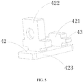
- the movable seat 40 includes a sliding groove 41 and a sliding component 42 which is accommodated in the sliding groove 41 and cooperates with the sliding groove 41, the sliding component 42 is fixedly connected with the first shell 102 and/or the second shell 103.
- the sliding groove 41 includes a sliding rail 411 cooperating with the sliding component 42 and a limiting plate 412 which limits the sliding distance of the sliding component 42.
- the sliding component 42 includes a limiting embossment 421 cooperating with the limiting plate 412, a fixing component 422 parallel to the limiting embossment 421 and a carrying plate 423 accommodated in the sliding rail 411 which carries the limiting embossment 421 and the fixing component 422, the fixing component 422 is fixed with the first shell 102 and/or the second shell 103 through bolt and nut.
- the limiting embossment 421 and the fixing component 422 are both provided with a supporting component 43 for cooperating with the sliding rail 411.
- the distance between the limiting embossment 421 and the fixing component 422 is much larger than the thickness of the connecting tab 101.
- the material of the movable seat 40 is nylon, so that both the sliding component 42 and the sliding groove 41 are relatively wear-resisting, which improves the service life of the power battery pack apparatus of the present invention.
- An insulating plate (not labeled) and a thermal conductive adhesive (not labeled) used for conducting heat of the battery are provided between the cell 10 and the base 40, the thermal conductive adhesive is provided under the insulating plate, the thermal conductive adhesive is configured to conduct the heat of the cell 10, so as to facilitate heat dissipation.
- the operating principle of the present invention is: the cell 10 is accommodated in the first shell 102 and the second shell 103, the first shell 102 and the second shell 103 are alternatively arranged, and are fixedly connected as a cell module by the connecting tab 101, the bolt 200, the bolt hole and the nut 201, the cell module is placed in the groove of the base 40, the outmost first shell 102 and second shell 103 are fixedly connected with the movable seat 40 through a connecting tab 101 respectively.
- the carrying plate 423 slides in from an end of the sliding groove 41, and is limited by the sliding rail 411 in vertical direction, adjusting the sliding component 42, so that the fixing component 422 is aligned with the connecting tab 101, and then fixing by using bolt and nut.
- the sliding component 42 slides to any of the two sides along the sliding rail 411, so that the cell 10 will not be blocked when expanding, moreover, the side plate 301 of the base 40 and the limiting embossment 421 of the movable seat 40 further limit the cell module, so as to prevent the cell module from sliding out of the groove.
- the supporting component 43 of the limiting embossment 421 and fixing component 422 on the movable seat 40 abut and press on the sliding rail 411, two supporting components 43 are provided at the front and back respectively, so as to balance the force subjected by the cell module.
- the movable seat 40 is adopted to prevent the cell module from being blocked by outer force when expanding, so that the cell 10 of the present invention can be fixed into a module quickly, and will not affect the battery expanding, that is, in the battery expanding process, it will not receive outer resistance, so as to improve safety of the battery and show better heat dissipation effect.
Landscapes
- Chemical & Material Sciences (AREA)
- Chemical Kinetics & Catalysis (AREA)
- Electrochemistry (AREA)
- General Chemical & Material Sciences (AREA)
- Engineering & Computer Science (AREA)
- Manufacturing & Machinery (AREA)
- Battery Mounting, Suspending (AREA)
Abstract
Description
- The present invention relates to a power battery pack apparatus and, particularly, relates to a module design of a power battery system.
- In traditional battery packing technology, the cell module is usually packed adopting an adhering manner. When structural adhesive is used to adhere the cells, if better adhesion of the adhesive is desired, a fixture must be used to clamp and fix the cells, and apply a pre-tightening force to the cell, so as to spread out the adhesive on the fitting surface of the cells. Such a structure exists the following defects:
- Firstly, different fixtures need to be designed for cells of different sizes, which will increase cost;
- Secondly, the cells need to be applied with a pre-tightening force, causing the cells be extruded, when the module is operating, the cells will expand, which increases the expanding force of the cells, and may greatly damage the structure of the module, resulting in a big risk of failure of the module.
- The technical problem to be solved by the present invention is to provide a power battery pack apparatus which is grouped quickly with high safety performance.
- A power battery pack apparatus, including a plurality of cells and connecting components,
- the plurality of cells are successively stacked along a thickness direction of the cell to form a cell module, each of the cells includes a cell main body and at least two connecting tabs,
- all of the connecting tabs are protruded from a side portion of the cell main body, and are fixed with the cell main body, at least a group of connecting tabs are arranged at the side portion of the cell main body between any two adjacent cells, and each group of the connecting tabs are connected through a connecting component, so that the two adjacent cells are connected with each other.
- Preferably, the connecting tab is fixed on the cell main body.
- Preferably, the cell further includes a shell, the cell main body is arranged in the shell, the connecting tab is fixed on the shell.
- Preferably, the connecting tabs of a cell for respectively connecting adjacent cells on both sides of the cell are spaced in a height direction of the cell.
- Preferably, a bolt hole is provided on the connecting tab, the connecting component includes a bolt and a nut, each group of the connecting tabs are connected by the bolt extending through the bolt hole and the nut.
- Preferably, further including a base carrying the cell and a plurality of movable seats,
- the plurality of movable seats are respectively arranged at two symmetrical sides of the base, the cells located at both ends of the cell module are fixedly arranged with the movable seats of corresponding sides, and the movable seats are able to slide along the thickness direction of the cell.
- Preferably, the movable seat includes a sliding groove and a sliding component which is accommodated in the sliding groove and cooperates with the sliding groove, the sliding groove is provided on the base along the thickness direction of the cell, the sliding component is connected with the cell.
- Preferably, the connecting tabs corresponding to the sliding component are arranged on the cells located at both ends of the cell module, the connecting tabs are connected with the sliding component through the connecting component, so that the cell is connected with the sliding component.
- Preferably, the sliding groove includes a sliding rail cooperating with the sliding component and a limiting plate which limits a sliding distance of the sliding component, the sliding component includes a limiting embossment cooperating with the limiting plate, a fixing component parallel to the limiting embossment and a carrying plate accommodated in the sliding rail which carries the limiting embossment and the fixing component, the fixing component is fixed with the cell.
- Preferably, both the limiting embossment and the fixing component are provided with a supporting component cooperating with the sliding rail.
- Preferably, a distance between the limiting embossment and the fixing component is larger than thickness of the connecting tab.
- In the power battery pack apparatus of the present invention, adjacent cells are fitted to be a pack through the connecting tabs and the connecting component, so that it is unnecessary for the power battery pack apparatus of the present invention to adopt a fixture, thereby saving cost, and also achieving quick fixing and packing, and thus will not affect expansion of the cell, that is, the cell will not be subjected to outer resistance during the expanding process, thereby improving safety.
- In order to illustrate the technical solutions in the embodiments of the present invention or the prior art more clearly, a brief introduction of the drawings used in the embodiments or the prior art will be provided here, obviously, the drawings described below are just some embodiments of the present invention, those skilled in the art can also obtain other drawings according to these drawings without creative work
-
FIG. 1 is an integral schematic diagram of a power battery pack apparatus of the present invention; -
FIG. 2 is a structural schematic diagram of a first cell of the present invention; -
FIG. 3 is a structural schematic diagram of a second cell of the present invention; -
FIG. 4 is a schematic diagram of a base inFIG. 1 ; -
FIG. 5 is an enlarged view of a sliding member inFIG. 1 . - For ease of understanding of the present invention, the present invention will be completely described referring to relevant drawings. The drawings provide preferred embodiments of the present invention. However, the present invention can be implemented in various forms, which is not limited to the embodiments described in the present disclosure. On the contrary, the objective of providing these embodiments is to achieve a clear and complete comprehension of the disclosed content of the present invention.
- Unless otherwise defined, all the techniques and scientific terminologies used in the present disclosure have the same meanings as those generally understood by those skilled in the art of the present invention. In the present disclosure, the terminologies used in the specification of the present invention are only used for the purpose of describing the specific embodiments, rather than limiting the present invention. The terminology "and/or" used in the present disclosure includes any and all combinations of one or more relevant items listed.
- Embodiments of the present invention will be described in detail with reference to the drawings.
- Please refer to
FIG. 1 , the present invention discloses a power battery pack apparatus (not labeled), the power battery pack apparatus includes a plurality ofcells 10, a connectingcomponent 20, abase 30 and amovable seat 40. - The drawing of the present embodiment shows eight
cells 10. Thesecells 10 are successively stacked along thickness direction to form a cell module. Eachcell 10 includes a cellmain body 100 and at least two connectingtabs 101, the connectingtabs 101 are all protruded from the side portion of the cellmain body 100, and need to be kept fixed with respect to the cellmain body 100. At least a group of oppositely arranged connectingtabs 101 should be provided at the side portion of the cellmain body 100 between any twoadjacent cells 10, it is preferred that a group of connectingtabs 101 should be provided at both sides of the two adjacent cellmain bodies 100 at the same time, so as to connect with each other. Each group of connectingtabs 101 is connected through a connectingcomponent 20, so that the twoadjacent cells 10 can be connected with each other. - The
adjacent cells 10 can be fitted tightly through the cooperation of the connectingtabs 101 and the connectingcomponent 20, so as to fix all thecells 10 to form a cell module, therefore, it is unnecessary to use a fixture, which saves cost, and also achieves the effect of quick fixing and packing. At the same time, since the connecting manner is to implement the connection at the side portion of the cell, which will not extrude the cell, and thus will not affect expansion of the cell, that is, the cell will not be subjected to outer resistance during expanding process, thereby improving safety. - In the present embodiment, the connecting
tab 101 has two fixing manners. As shown inFIG. 2 , the first manner is to fix the connectingtab 101 on the cellmain body 100. As shown inFIG. 3 , the second manner is to arrange the connectingtab 101 on a shell in advance, and then arrange the cellmain body 100 in the shell. Specifically, as shown inFIG. 1 , the shell can be divided into two different structures: afirst shell 102 and asecond shell 103. - A connecting
tab 101 is protruded from both the upside and the downside of thefirst shell 102, and a connectingtab 101 is also protruded from both the upside and the downside of thesecond shell 103. Thefirst shell 102 and thesecond shell 103 are alternatively arranged, the connectingtabs 101 located at the upsides of thefirst shell 102 and thesecond shell 103 form a group, and the connectingtabs 101 located at the downsides thereof also form a group. Each group of connectingtabs 101 can be connected through a connectingcomponent 20, respectively. - In the present embodiment, the number of the connecting
tabs 102 on thefirst shell 102 and thesecond shell 103 is not limited to four, which can be added according to needs. The connectingtabs 101 for connecting withother cells 10 at both sides are arranged on the upside and downside of eachcell 10, so that they can have enough space to assemble the connecting components. Absolutely, if thecell 10 is thick enough, all the connectingtabs 101 can be arranged at the same height. - In order to connect the connecting
component 20 conveniently, the group of connectingtabs 101 located on thefirst shell 102 and thesecond shell 103 can be arranged close to each other. The connectingtabs 101 can be welded on thefirst shell 102 and thesecond shell 103 through a welding manner, and can also be integrated as a whole on thefirst shell 102 and thesecond shell 103. - The connecting
component 20 can adopt connecting structures such as clamping, riveting, screwing and the like. For example, a bolt hole (not labeled) is provided on all the connectingtabs 101, the connectingcomponent 20 includes abolt 200 and anut 201, each group of connectingtabs 101 is connected through thebolt 200 extending through the bolt hole and thenut 201. - As shown in
FIG. 4 , in the present embodiment, thebase 30 is adopted to fix the cell module, thebase 30 includes abase plate 300 and fourside plates 301 which are protruded from the edge of thebase plate 300 and are perpendicular to thebase plate 300, theside plates 301 encloses to form a rectangle frame (not labeled). A plurality ofmovable seats 40 are provided, which are arranged respectively at the symmetrical sides of thebase 30, in the present embodiment, a pair ofmovable seats 40 can be arranged on a pair ofparallel side plates 301, respectively. And thecells 10 located at both ends of the cell module are fixedly arranged with themovable seat 40 of corresponding sides. Themovable seat 40 is configured to connect the cell module with thebase 30, so as to fix the cell module on thebase 30. At the same time, themovable seat 40 can also slide with respect to thebase 30 for a certain extent, so that the cell will not be constrained when expanding, so as to improve safety. - The rectangle frame and the
base plate 300 form a big groove, so as to accommodate the cell module which has been fixed tightly. And the height of theside plate 301 is less than the height of the connectingtab 101, so as to avoid the packedcells 10 from conflicting with theside plate 301 during the sliding process, thereby improving the safety and service life of the module. Thebase 30 is made of aluminum alloy material, such arrangement makes the base 30 lightweight and be able to conduct the heat dissipated by the battery effectively, which is convenient for heat dissipation. - As shown in
FIG. 5 , themovable seat 40 includes a slidinggroove 41 and a slidingcomponent 42 which is accommodated in the slidinggroove 41 and cooperates with the slidinggroove 41, the slidingcomponent 42 is fixedly connected with thefirst shell 102 and/or thesecond shell 103. The slidinggroove 41 includes a slidingrail 411 cooperating with the slidingcomponent 42 and a limitingplate 412 which limits the sliding distance of the slidingcomponent 42. The slidingcomponent 42 includes a limitingembossment 421 cooperating with the limitingplate 412, afixing component 422 parallel to the limitingembossment 421 and a carryingplate 423 accommodated in the slidingrail 411 which carries the limitingembossment 421 and thefixing component 422, the fixingcomponent 422 is fixed with thefirst shell 102 and/or thesecond shell 103 through bolt and nut. The limitingembossment 421 and thefixing component 422 are both provided with a supportingcomponent 43 for cooperating with the slidingrail 411. The distance between the limitingembossment 421 and thefixing component 422 is much larger than the thickness of the connectingtab 101. The material of themovable seat 40 is nylon, so that both the slidingcomponent 42 and the slidinggroove 41 are relatively wear-resisting, which improves the service life of the power battery pack apparatus of the present invention. - An insulating plate (not labeled) and a thermal conductive adhesive (not labeled) used for conducting heat of the battery are provided between the
cell 10 and thebase 40, the thermal conductive adhesive is provided under the insulating plate, the thermal conductive adhesive is configured to conduct the heat of thecell 10, so as to facilitate heat dissipation. - The operating principle of the present invention is: the
cell 10 is accommodated in thefirst shell 102 and thesecond shell 103, thefirst shell 102 and thesecond shell 103 are alternatively arranged, and are fixedly connected as a cell module by the connectingtab 101, thebolt 200, the bolt hole and thenut 201, the cell module is placed in the groove of thebase 40, the outmostfirst shell 102 andsecond shell 103 are fixedly connected with themovable seat 40 through a connectingtab 101 respectively. - The carrying
plate 423 slides in from an end of the slidinggroove 41, and is limited by the slidingrail 411 in vertical direction, adjusting the slidingcomponent 42, so that the fixingcomponent 422 is aligned with the connectingtab 101, and then fixing by using bolt and nut. When the cell module is expanding in the groove, the slidingcomponent 42 slides to any of the two sides along the slidingrail 411, so that thecell 10 will not be blocked when expanding, moreover, theside plate 301 of thebase 40 and the limitingembossment 421 of themovable seat 40 further limit the cell module, so as to prevent the cell module from sliding out of the groove. - The supporting
component 43 of the limitingembossment 421 and fixingcomponent 422 on themovable seat 40 abut and press on the slidingrail 411, two supportingcomponents 43 are provided at the front and back respectively, so as to balance the force subjected by the cell module. - In the power battery pack apparatus of the present invention, eight
cells 10 through are packed into a module through thefirst shell 102 and thesecond shell 103 accommodating thecell 10, and then connecting and fixing thefirst shell 102 and thesecond shell 103 through thebolt 200 and thenut 201, at the same time, themovable seat 40 is adopted to prevent the cell module from being blocked by outer force when expanding, so that thecell 10 of the present invention can be fixed into a module quickly, and will not affect the battery expanding, that is, in the battery expanding process, it will not receive outer resistance, so as to improve safety of the battery and show better heat dissipation effect. - The above-mentioned embodiments only illustrate several implementing manners of the present invention, the description thereof are specific and in detail, which, however, cannot be understood as the limitation of the protection scope of the present invention. It should be understood that, for those skilled in the art, various transformations and improvements can be proposed without departing from the conception of the present invention, all of which shall belong to the protection scope of the present invention. Therefore, the protection scope of the present invention should be subject to the accompanying claims.
Claims (11)
- A power battery pack apparatus, characterized in that, comprising a plurality of cells and connecting components,
the plurality of cells are successively stacked along a thickness direction of the cell to form a cell module, each of the cells comprises a cell main body and at least two connecting tabs,
all of the connecting tabs are protruded from a side portion of the cell main body, and are fixed with the cell main body, at least a group of connecting tabs are arranged at the side portion of the cell main body between any two adjacent cells, and each group of the connecting tabs are connected through a connecting component, so that the two adjacent cells are connected with each other. - The power battery pack apparatus according to claim 1, characterized in that, the connecting tab is fixed on the cell main body.
- The power battery pack apparatus according to claim 1, characterized in that, the cell further comprises a shell, the cell main body is arranged in the shell, the connecting tab is fixed on the shell.
- The power battery pack apparatus according to claim 2 or 3, characterized in that, the connecting tabs of a cell for respectively connecting adjacent cells on both sides of the cell are spaced in a height direction of the cell.
- The power battery pack apparatus according to any one of claims 1-3, characterized in that, a bolt hole is provided on the connecting tab, the connecting component comprises a bolt and a nut, each group of the connecting tabs are connected by the bolt extending through the bolt hole and the nut.
- The power battery pack apparatus according to any one of claims 1-3, characterized in that, further comprising a base carrying the cell and a plurality of movable seats,
the plurality of movable seats are respectively arranged at two symmetrical sides of the base, the cells located at both ends of the cell module are fixedly arranged with the movable seats of corresponding sides, and the movable seats are able to slide along the thickness direction of the cell. - The power battery pack apparatus according to claim 6, characterized in that, the movable seat comprises a sliding groove and a sliding component which is accommodated in the sliding groove and cooperates with the sliding groove, the sliding groove is provided on the base along the thickness direction of the cell, the sliding component is connected with the cell.
- The power battery pack apparatus according to claim 7, characterized in that, the connecting tabs corresponding to the sliding component are arranged on the cells located at both ends of the cell module, the connecting tabs are connected with the sliding component through the connecting component, so that the cell is connected with the sliding component.
- The power battery pack apparatus according to claim 8, characterized in that, the sliding groove comprises a sliding rail cooperating with the sliding component and a limiting plate which limits a sliding distance of the sliding component, the sliding component comprises a limiting embossment cooperating with the limiting plate, a fixing component parallel to the limiting embossment and a carrying plate accommodated in the sliding rail which carries the limiting embossment and the fixing component, the fixing component is fixed with the cell.
- The power battery pack apparatus according to claim 9, characterized in that, both the limiting embossment and the fixing component are provided with a supporting component cooperating with the sliding rail.
- The power battery pack apparatus according to claim 10, characterized in that, a distance between the limiting embossment and the fixing component is larger than thickness of the connecting tab.
Applications Claiming Priority (1)
| Application Number | Priority Date | Filing Date | Title |
|---|---|---|---|
| CN201610109698.XA CN105591060B (en) | 2016-02-25 | 2016-02-25 | Power battery pack device |
Publications (2)
| Publication Number | Publication Date |
|---|---|
| EP3211686A1 true EP3211686A1 (en) | 2017-08-30 |
| EP3211686B1 EP3211686B1 (en) | 2019-03-13 |
Family
ID=55930469
Family Applications (1)
| Application Number | Title | Priority Date | Filing Date |
|---|---|---|---|
| EP16202751.0A Active EP3211686B1 (en) | 2016-02-25 | 2016-12-07 | Power battery pack apparatus |
Country Status (3)
| Country | Link |
|---|---|
| US (1) | US20170250386A1 (en) |
| EP (1) | EP3211686B1 (en) |
| CN (1) | CN105591060B (en) |
Cited By (1)
| Publication number | Priority date | Publication date | Assignee | Title |
|---|---|---|---|---|
| EP3506386A1 (en) * | 2017-12-28 | 2019-07-03 | Contemporary Amperex Technology Co., Limited | Shell, battery module and battery pack |
Families Citing this family (12)
| Publication number | Priority date | Publication date | Assignee | Title |
|---|---|---|---|---|
| CN109103385B (en) * | 2018-09-25 | 2024-09-20 | 华霆(合肥)动力技术有限公司 | Soft package battery box and battery module |
| US12410300B2 (en) | 2018-10-12 | 2025-09-09 | Ppg Industries Ohio, Inc. | Compositions containing thermally conductive fillers |
| CN109687190B (en) * | 2018-11-22 | 2022-05-27 | 福建省汽车工业集团云度新能源汽车股份有限公司 | Battery pack internal opposite-insertion module and module unit |
| CN110379969B (en) * | 2019-07-26 | 2022-03-22 | 贵州大学 | Equipment shell of new forms of energy electric automobile battery |
| US12630740B2 (en) | 2019-12-11 | 2026-05-19 | Ppg Industries Ohio, Inc. | Compositions containing thermally conductive fillers |
| CN111883712B (en) * | 2020-08-14 | 2024-10-25 | 傲普(上海)新能源有限公司 | Energy storage battery cabinet |
| CN113206338B (en) * | 2021-03-24 | 2024-08-16 | 合众新能源汽车股份有限公司 | A structure for delaying thermal runaway time of electric vehicle power battery |
| JP7349029B2 (en) * | 2021-05-20 | 2023-09-21 | 寧徳時代新能源科技股▲分▼有限公司 | Lithium ion secondary batteries, battery modules, battery packs and electrical devices |
| CN113839138B (en) * | 2021-09-22 | 2024-02-23 | 蜂巢能源科技有限公司 | Installation bracket, battery module and battery pack |
| CN115117533A (en) * | 2022-06-02 | 2022-09-27 | 远景动力技术(江苏)有限公司 | Battery module and electronic device |
| CN116691564A (en) * | 2023-06-13 | 2023-09-05 | 北京嘉诚兴业工贸股份有限公司 | Battery tray structure of passenger car |
| CN116960560B (en) * | 2023-09-19 | 2024-01-05 | 中宏科创新能源科技(浙江)有限公司 | Battery clamping device, mounting method, dismounting method and adjusting method thereof |
Citations (6)
| Publication number | Priority date | Publication date | Assignee | Title |
|---|---|---|---|---|
| US20110014512A1 (en) * | 2008-02-29 | 2011-01-20 | Nissan Motor Co., Ltd. | Battery module and manufacturing method of battery module |
| US20120135288A1 (en) * | 2009-02-27 | 2012-05-31 | Li-Tec Battery Gmbh | Galvanic cell having a frame and method for the production of said galvanic cell |
| US20130209850A1 (en) * | 2012-02-14 | 2013-08-15 | Sumitomo Heavy Industries, Ltd. | Power storage module, manufacturing method thereof, and working machine |
| JP2014175078A (en) * | 2013-03-06 | 2014-09-22 | Captex Co Ltd | Battery pack |
| KR20150012413A (en) * | 2013-07-25 | 2015-02-04 | 주식회사 엘지화학 | Battery Module Having Movable Pressurization Member |
| EP2833434A1 (en) * | 2012-03-27 | 2015-02-04 | Sony Corporation | Galvanic unit, galvanic module, power storage system, electronic equipment, electric power system, and electric vehicle |
Family Cites Families (6)
| Publication number | Priority date | Publication date | Assignee | Title |
|---|---|---|---|---|
| KR100903185B1 (en) * | 2005-05-02 | 2009-06-17 | 주식회사 엘지화학 | Improved medium and large battery packs with improved safety |
| EP2710843B1 (en) * | 2011-05-17 | 2015-03-18 | Telefonaktiebolaget L M Ericsson (Publ) | Method and arrangement for supporting calibration of correlated antennas |
| JP6281398B2 (en) * | 2014-04-21 | 2018-02-21 | 株式会社豊田自動織機 | Battery module |
| EP3161899A4 (en) * | 2014-06-30 | 2017-12-27 | Black & Decker Inc. | Battery pack for a cordless power tools |
| CN204315650U (en) * | 2015-01-05 | 2015-05-06 | 天津市捷威动力工业有限公司 | A kind of collapsible battery core assembling frame |
| CN205355134U (en) * | 2016-02-25 | 2016-06-29 | 宁德时代新能源科技股份有限公司 | Power battery equipment is put |
-
2016
- 2016-02-25 CN CN201610109698.XA patent/CN105591060B/en active Active
- 2016-12-07 EP EP16202751.0A patent/EP3211686B1/en active Active
-
2017
- 2017-02-17 US US15/436,687 patent/US20170250386A1/en not_active Abandoned
Patent Citations (7)
| Publication number | Priority date | Publication date | Assignee | Title |
|---|---|---|---|---|
| US20110014512A1 (en) * | 2008-02-29 | 2011-01-20 | Nissan Motor Co., Ltd. | Battery module and manufacturing method of battery module |
| US20120135288A1 (en) * | 2009-02-27 | 2012-05-31 | Li-Tec Battery Gmbh | Galvanic cell having a frame and method for the production of said galvanic cell |
| US20130209850A1 (en) * | 2012-02-14 | 2013-08-15 | Sumitomo Heavy Industries, Ltd. | Power storage module, manufacturing method thereof, and working machine |
| EP2833434A1 (en) * | 2012-03-27 | 2015-02-04 | Sony Corporation | Galvanic unit, galvanic module, power storage system, electronic equipment, electric power system, and electric vehicle |
| JP2014175078A (en) * | 2013-03-06 | 2014-09-22 | Captex Co Ltd | Battery pack |
| KR20150012413A (en) * | 2013-07-25 | 2015-02-04 | 주식회사 엘지화학 | Battery Module Having Movable Pressurization Member |
| US20160133892A1 (en) * | 2013-07-25 | 2016-05-12 | Lg Chem, Ltd. | Battery module having movable pressurization member |
Cited By (2)
| Publication number | Priority date | Publication date | Assignee | Title |
|---|---|---|---|---|
| EP3506386A1 (en) * | 2017-12-28 | 2019-07-03 | Contemporary Amperex Technology Co., Limited | Shell, battery module and battery pack |
| US10826033B2 (en) | 2017-12-28 | 2020-11-03 | Contemporary Amperex Technology Co., Limited | Shell, battery module and battery pack |
Also Published As
| Publication number | Publication date |
|---|---|
| CN105591060A (en) | 2016-05-18 |
| US20170250386A1 (en) | 2017-08-31 |
| EP3211686B1 (en) | 2019-03-13 |
| CN105591060B (en) | 2019-09-03 |
Similar Documents
| Publication | Publication Date | Title |
|---|---|---|
| EP3211686B1 (en) | Power battery pack apparatus | |
| US9716297B2 (en) | Energy storage module and system | |
| US10439178B2 (en) | In-vehicle battery module | |
| US11437667B2 (en) | Battery assembly method for providing a battery arrangement and battery arrangement | |
| US8524387B2 (en) | Battery unit for hybrid or electric vehicles | |
| JP5677177B2 (en) | Battery assembly | |
| US9601815B2 (en) | Battery system having battery cells and an apparatus for controlling the temperature of the battery cells | |
| US20140038021A1 (en) | Energy Storage Module Comprising a Plurality of Prismatic Storage Cells | |
| US20170237113A1 (en) | Receptacle for a battery module, and battery module having a receptacle of this kind | |
| US20190334137A1 (en) | Battery pack | |
| CN108461685A (en) | Battery pack and its Battery case | |
| US9768465B2 (en) | Battery module | |
| US10461382B2 (en) | Receptacle for a battery module and battery module having such a receptacle | |
| WO2021093084A1 (en) | Battery module grouping clamp and usage method | |
| DE102011007069A1 (en) | Electric energy storage device having a plurality of cells and at least one cooling element arranged between the cells | |
| WO2015186501A1 (en) | Battery module and battery pack | |
| US20150180097A1 (en) | Energy Storage Module and Method for Production of Energy Storage Module | |
| US20210344070A1 (en) | Battery module including nodal cell compression and heat rejection | |
| DE102015011281A1 (en) | Cell block for an electric battery | |
| JP2016500474A (en) | Semiconductor assembly | |
| CN209998634U (en) | welding tool suitable for battery module | |
| CN211195886U (en) | New forms of energy electric automobile battery package backplate mounting structure | |
| CN205355134U (en) | Power battery equipment is put | |
| US20160064784A1 (en) | Battery module | |
| US20190234688A1 (en) | Device for cooling an energy storage unit, and associated assembly |
Legal Events
| Date | Code | Title | Description |
|---|---|---|---|
| PUAI | Public reference made under article 153(3) epc to a published international application that has entered the european phase |
Free format text: ORIGINAL CODE: 0009012 |
|
| STAA | Information on the status of an ep patent application or granted ep patent |
Free format text: STATUS: REQUEST FOR EXAMINATION WAS MADE |
|
| 17P | Request for examination filed |
Effective date: 20161207 |
|
| AK | Designated contracting states |
Kind code of ref document: A1 Designated state(s): AL AT BE BG CH CY CZ DE DK EE ES FI FR GB GR HR HU IE IS IT LI LT LU LV MC MK MT NL NO PL PT RO RS SE SI SK SM TR |
|
| AX | Request for extension of the european patent |
Extension state: BA ME |
|
| STAA | Information on the status of an ep patent application or granted ep patent |
Free format text: STATUS: EXAMINATION IS IN PROGRESS |
|
| 17Q | First examination report despatched |
Effective date: 20180611 |
|
| GRAP | Despatch of communication of intention to grant a patent |
Free format text: ORIGINAL CODE: EPIDOSNIGR1 |
|
| STAA | Information on the status of an ep patent application or granted ep patent |
Free format text: STATUS: GRANT OF PATENT IS INTENDED |
|
| INTG | Intention to grant announced |
Effective date: 20181019 |
|
| GRAS | Grant fee paid |
Free format text: ORIGINAL CODE: EPIDOSNIGR3 |
|
| GRAA | (expected) grant |
Free format text: ORIGINAL CODE: 0009210 |
|
| STAA | Information on the status of an ep patent application or granted ep patent |
Free format text: STATUS: THE PATENT HAS BEEN GRANTED |
|
| AK | Designated contracting states |
Kind code of ref document: B1 Designated state(s): AL AT BE BG CH CY CZ DE DK EE ES FI FR GB GR HR HU IE IS IT LI LT LU LV MC MK MT NL NO PL PT RO RS SE SI SK SM TR |
|
| REG | Reference to a national code |
Ref country code: GB Ref legal event code: FG4D |
|
| REG | Reference to a national code |
Ref country code: CH Ref legal event code: EP Ref country code: AT Ref legal event code: REF Ref document number: 1108915 Country of ref document: AT Kind code of ref document: T Effective date: 20190315 |
|
| REG | Reference to a national code |
Ref country code: DE Ref legal event code: R096 Ref document number: 602016010986 Country of ref document: DE |
|
| REG | Reference to a national code |
Ref country code: IE Ref legal event code: FG4D |
|
| REG | Reference to a national code |
Ref country code: NL Ref legal event code: MP Effective date: 20190313 |
|
| REG | Reference to a national code |
Ref country code: LT Ref legal event code: MG4D |
|
| PG25 | Lapsed in a contracting state [announced via postgrant information from national office to epo] |
Ref country code: SE Free format text: LAPSE BECAUSE OF FAILURE TO SUBMIT A TRANSLATION OF THE DESCRIPTION OR TO PAY THE FEE WITHIN THE PRESCRIBED TIME-LIMIT Effective date: 20190313 Ref country code: FI Free format text: LAPSE BECAUSE OF FAILURE TO SUBMIT A TRANSLATION OF THE DESCRIPTION OR TO PAY THE FEE WITHIN THE PRESCRIBED TIME-LIMIT Effective date: 20190313 Ref country code: NO Free format text: LAPSE BECAUSE OF FAILURE TO SUBMIT A TRANSLATION OF THE DESCRIPTION OR TO PAY THE FEE WITHIN THE PRESCRIBED TIME-LIMIT Effective date: 20190613 Ref country code: LT Free format text: LAPSE BECAUSE OF FAILURE TO SUBMIT A TRANSLATION OF THE DESCRIPTION OR TO PAY THE FEE WITHIN THE PRESCRIBED TIME-LIMIT Effective date: 20190313 |
|
| PG25 | Lapsed in a contracting state [announced via postgrant information from national office to epo] |
Ref country code: BG Free format text: LAPSE BECAUSE OF FAILURE TO SUBMIT A TRANSLATION OF THE DESCRIPTION OR TO PAY THE FEE WITHIN THE PRESCRIBED TIME-LIMIT Effective date: 20190613 Ref country code: GR Free format text: LAPSE BECAUSE OF FAILURE TO SUBMIT A TRANSLATION OF THE DESCRIPTION OR TO PAY THE FEE WITHIN THE PRESCRIBED TIME-LIMIT Effective date: 20190614 Ref country code: HR Free format text: LAPSE BECAUSE OF FAILURE TO SUBMIT A TRANSLATION OF THE DESCRIPTION OR TO PAY THE FEE WITHIN THE PRESCRIBED TIME-LIMIT Effective date: 20190313 Ref country code: LV Free format text: LAPSE BECAUSE OF FAILURE TO SUBMIT A TRANSLATION OF THE DESCRIPTION OR TO PAY THE FEE WITHIN THE PRESCRIBED TIME-LIMIT Effective date: 20190313 Ref country code: NL Free format text: LAPSE BECAUSE OF FAILURE TO SUBMIT A TRANSLATION OF THE DESCRIPTION OR TO PAY THE FEE WITHIN THE PRESCRIBED TIME-LIMIT Effective date: 20190313 Ref country code: RS Free format text: LAPSE BECAUSE OF FAILURE TO SUBMIT A TRANSLATION OF THE DESCRIPTION OR TO PAY THE FEE WITHIN THE PRESCRIBED TIME-LIMIT Effective date: 20190313 |
|
| REG | Reference to a national code |
Ref country code: AT Ref legal event code: MK05 Ref document number: 1108915 Country of ref document: AT Kind code of ref document: T Effective date: 20190313 |
|
| PG25 | Lapsed in a contracting state [announced via postgrant information from national office to epo] |
Ref country code: CZ Free format text: LAPSE BECAUSE OF FAILURE TO SUBMIT A TRANSLATION OF THE DESCRIPTION OR TO PAY THE FEE WITHIN THE PRESCRIBED TIME-LIMIT Effective date: 20190313 Ref country code: IT Free format text: LAPSE BECAUSE OF FAILURE TO SUBMIT A TRANSLATION OF THE DESCRIPTION OR TO PAY THE FEE WITHIN THE PRESCRIBED TIME-LIMIT Effective date: 20190313 Ref country code: ES Free format text: LAPSE BECAUSE OF FAILURE TO SUBMIT A TRANSLATION OF THE DESCRIPTION OR TO PAY THE FEE WITHIN THE PRESCRIBED TIME-LIMIT Effective date: 20190313 Ref country code: RO Free format text: LAPSE BECAUSE OF FAILURE TO SUBMIT A TRANSLATION OF THE DESCRIPTION OR TO PAY THE FEE WITHIN THE PRESCRIBED TIME-LIMIT Effective date: 20190313 Ref country code: EE Free format text: LAPSE BECAUSE OF FAILURE TO SUBMIT A TRANSLATION OF THE DESCRIPTION OR TO PAY THE FEE WITHIN THE PRESCRIBED TIME-LIMIT Effective date: 20190313 Ref country code: PT Free format text: LAPSE BECAUSE OF FAILURE TO SUBMIT A TRANSLATION OF THE DESCRIPTION OR TO PAY THE FEE WITHIN THE PRESCRIBED TIME-LIMIT Effective date: 20190713 Ref country code: SK Free format text: LAPSE BECAUSE OF FAILURE TO SUBMIT A TRANSLATION OF THE DESCRIPTION OR TO PAY THE FEE WITHIN THE PRESCRIBED TIME-LIMIT Effective date: 20190313 Ref country code: AL Free format text: LAPSE BECAUSE OF FAILURE TO SUBMIT A TRANSLATION OF THE DESCRIPTION OR TO PAY THE FEE WITHIN THE PRESCRIBED TIME-LIMIT Effective date: 20190313 |
|
| PG25 | Lapsed in a contracting state [announced via postgrant information from national office to epo] |
Ref country code: PL Free format text: LAPSE BECAUSE OF FAILURE TO SUBMIT A TRANSLATION OF THE DESCRIPTION OR TO PAY THE FEE WITHIN THE PRESCRIBED TIME-LIMIT Effective date: 20190313 Ref country code: SM Free format text: LAPSE BECAUSE OF FAILURE TO SUBMIT A TRANSLATION OF THE DESCRIPTION OR TO PAY THE FEE WITHIN THE PRESCRIBED TIME-LIMIT Effective date: 20190313 |
|
| REG | Reference to a national code |
Ref country code: DE Ref legal event code: R097 Ref document number: 602016010986 Country of ref document: DE |
|
| PG25 | Lapsed in a contracting state [announced via postgrant information from national office to epo] |
Ref country code: AT Free format text: LAPSE BECAUSE OF FAILURE TO SUBMIT A TRANSLATION OF THE DESCRIPTION OR TO PAY THE FEE WITHIN THE PRESCRIBED TIME-LIMIT Effective date: 20190313 Ref country code: IS Free format text: LAPSE BECAUSE OF FAILURE TO SUBMIT A TRANSLATION OF THE DESCRIPTION OR TO PAY THE FEE WITHIN THE PRESCRIBED TIME-LIMIT Effective date: 20190713 |
|
| PLBE | No opposition filed within time limit |
Free format text: ORIGINAL CODE: 0009261 |
|
| STAA | Information on the status of an ep patent application or granted ep patent |
Free format text: STATUS: NO OPPOSITION FILED WITHIN TIME LIMIT |
|
| PG25 | Lapsed in a contracting state [announced via postgrant information from national office to epo] |
Ref country code: DK Free format text: LAPSE BECAUSE OF FAILURE TO SUBMIT A TRANSLATION OF THE DESCRIPTION OR TO PAY THE FEE WITHIN THE PRESCRIBED TIME-LIMIT Effective date: 20190313 |
|
| 26N | No opposition filed |
Effective date: 20191216 |
|
| PG25 | Lapsed in a contracting state [announced via postgrant information from national office to epo] |
Ref country code: SI Free format text: LAPSE BECAUSE OF FAILURE TO SUBMIT A TRANSLATION OF THE DESCRIPTION OR TO PAY THE FEE WITHIN THE PRESCRIBED TIME-LIMIT Effective date: 20190313 |
|
| PG25 | Lapsed in a contracting state [announced via postgrant information from national office to epo] |
Ref country code: TR Free format text: LAPSE BECAUSE OF FAILURE TO SUBMIT A TRANSLATION OF THE DESCRIPTION OR TO PAY THE FEE WITHIN THE PRESCRIBED TIME-LIMIT Effective date: 20190313 |
|
| REG | Reference to a national code |
Ref country code: CH Ref legal event code: PL |
|
| REG | Reference to a national code |
Ref country code: BE Ref legal event code: MM Effective date: 20191231 |
|
| PG25 | Lapsed in a contracting state [announced via postgrant information from national office to epo] |
Ref country code: MC Free format text: LAPSE BECAUSE OF FAILURE TO SUBMIT A TRANSLATION OF THE DESCRIPTION OR TO PAY THE FEE WITHIN THE PRESCRIBED TIME-LIMIT Effective date: 20190313 |
|
| PG25 | Lapsed in a contracting state [announced via postgrant information from national office to epo] |
Ref country code: IE Free format text: LAPSE BECAUSE OF NON-PAYMENT OF DUE FEES Effective date: 20191207 Ref country code: LU Free format text: LAPSE BECAUSE OF NON-PAYMENT OF DUE FEES Effective date: 20191207 |
|
| REG | Reference to a national code |
Ref country code: DE Ref legal event code: R079 Ref document number: 602016010986 Country of ref document: DE Free format text: PREVIOUS MAIN CLASS: H01M0002020000 Ipc: H01M0050100000 |
|
| PG25 | Lapsed in a contracting state [announced via postgrant information from national office to epo] |
Ref country code: CH Free format text: LAPSE BECAUSE OF NON-PAYMENT OF DUE FEES Effective date: 20191231 Ref country code: BE Free format text: LAPSE BECAUSE OF NON-PAYMENT OF DUE FEES Effective date: 20191231 Ref country code: LI Free format text: LAPSE BECAUSE OF NON-PAYMENT OF DUE FEES Effective date: 20191231 |
|
| PG25 | Lapsed in a contracting state [announced via postgrant information from national office to epo] |
Ref country code: CY Free format text: LAPSE BECAUSE OF FAILURE TO SUBMIT A TRANSLATION OF THE DESCRIPTION OR TO PAY THE FEE WITHIN THE PRESCRIBED TIME-LIMIT Effective date: 20190313 |
|
| PG25 | Lapsed in a contracting state [announced via postgrant information from national office to epo] |
Ref country code: HU Free format text: LAPSE BECAUSE OF FAILURE TO SUBMIT A TRANSLATION OF THE DESCRIPTION OR TO PAY THE FEE WITHIN THE PRESCRIBED TIME-LIMIT; INVALID AB INITIO Effective date: 20161207 Ref country code: MT Free format text: LAPSE BECAUSE OF FAILURE TO SUBMIT A TRANSLATION OF THE DESCRIPTION OR TO PAY THE FEE WITHIN THE PRESCRIBED TIME-LIMIT Effective date: 20190313 |
|
| PG25 | Lapsed in a contracting state [announced via postgrant information from national office to epo] |
Ref country code: MK Free format text: LAPSE BECAUSE OF FAILURE TO SUBMIT A TRANSLATION OF THE DESCRIPTION OR TO PAY THE FEE WITHIN THE PRESCRIBED TIME-LIMIT Effective date: 20190313 |
|
| P01 | Opt-out of the competence of the unified patent court (upc) registered |
Effective date: 20230516 |
|
| REG | Reference to a national code |
Ref country code: DE Ref legal event code: R082 Ref document number: 602016010986 Country of ref document: DE Ref country code: DE Ref legal event code: R081 Ref document number: 602016010986 Country of ref document: DE Owner name: CONTEMPORARY AMPEREX TECHNOLOGY (HONG KONG) LI, HK Free format text: FORMER OWNER: CONTEMPORARY AMPEREX TECHNOLOGY CO., LTD., NINGDE CITY, FUJIAN, CN |
|
| REG | Reference to a national code |
Ref country code: GB Ref legal event code: 732E Free format text: REGISTERED BETWEEN 20240815 AND 20240821 |
|
| PGFP | Annual fee paid to national office [announced via postgrant information from national office to epo] |
Ref country code: FR Payment date: 20250930 Year of fee payment: 10 |
|
| PGFP | Annual fee paid to national office [announced via postgrant information from national office to epo] |
Ref country code: DE Payment date: 20250930 Year of fee payment: 10 |
|
| PGFP | Annual fee paid to national office [announced via postgrant information from national office to epo] |
Ref country code: GB Payment date: 20251001 Year of fee payment: 10 |