EP3211441A1 - Method and system for measuring battery power of mobile communication terminal device - Google Patents
Method and system for measuring battery power of mobile communication terminal device Download PDFInfo
- Publication number
- EP3211441A1 EP3211441A1 EP16777886.9A EP16777886A EP3211441A1 EP 3211441 A1 EP3211441 A1 EP 3211441A1 EP 16777886 A EP16777886 A EP 16777886A EP 3211441 A1 EP3211441 A1 EP 3211441A1
- Authority
- EP
- European Patent Office
- Prior art keywords
- voltage value
- radio frequency
- transmitting
- battery
- measuring
- Prior art date
- Legal status (The legal status is an assumption and is not a legal conclusion. Google has not performed a legal analysis and makes no representation as to the accuracy of the status listed.)
- Withdrawn
Links
- 238000010295 mobile communication Methods 0.000 title claims abstract description 42
- 238000000034 method Methods 0.000 title claims abstract description 32
- 238000010586 diagram Methods 0.000 description 11
- 238000012545 processing Methods 0.000 description 10
- 238000004590 computer program Methods 0.000 description 7
- 238000005259 measurement Methods 0.000 description 6
- 230000032683 aging Effects 0.000 description 3
- 238000005516 engineering process Methods 0.000 description 3
- 230000006870 function Effects 0.000 description 3
- 238000000691 measurement method Methods 0.000 description 3
- 238000012986 modification Methods 0.000 description 2
- 230000004048 modification Effects 0.000 description 2
- 238000006467 substitution reaction Methods 0.000 description 2
- 230000006978 adaptation Effects 0.000 description 1
- 238000004891 communication Methods 0.000 description 1
- 230000008569 process Effects 0.000 description 1
- 238000011282 treatment Methods 0.000 description 1
Images



Classifications
-
- H—ELECTRICITY
- H04—ELECTRIC COMMUNICATION TECHNIQUE
- H04B—TRANSMISSION
- H04B17/00—Monitoring; Testing
- H04B17/10—Monitoring; Testing of transmitters
- H04B17/101—Monitoring; Testing of transmitters for measurement of specific parameters of the transmitter or components thereof
- H04B17/103—Reflected power, e.g. return loss
-
- H—ELECTRICITY
- H04—ELECTRIC COMMUNICATION TECHNIQUE
- H04W—WIRELESS COMMUNICATION NETWORKS
- H04W52/00—Power management, e.g. Transmission Power Control [TPC] or power classes
- H04W52/02—Power saving arrangements
- H04W52/0209—Power saving arrangements in terminal devices
- H04W52/0261—Power saving arrangements in terminal devices managing power supply demand, e.g. depending on battery level
- H04W52/0274—Power saving arrangements in terminal devices managing power supply demand, e.g. depending on battery level by switching on or off the equipment or parts thereof
- H04W52/0277—Power saving arrangements in terminal devices managing power supply demand, e.g. depending on battery level by switching on or off the equipment or parts thereof according to available power supply, e.g. switching off when a low battery condition is detected
-
- G—PHYSICS
- G01—MEASURING; TESTING
- G01R—MEASURING ELECTRIC VARIABLES; MEASURING MAGNETIC VARIABLES
- G01R31/00—Arrangements for testing electric properties; Arrangements for locating electric faults; Arrangements for electrical testing characterised by what is being tested not provided for elsewhere
- G01R31/36—Arrangements for testing, measuring or monitoring the electrical condition of accumulators or electric batteries, e.g. capacity or state of charge [SoC]
- G01R31/385—Arrangements for measuring battery or accumulator variables
-
- G—PHYSICS
- G01—MEASURING; TESTING
- G01R—MEASURING ELECTRIC VARIABLES; MEASURING MAGNETIC VARIABLES
- G01R31/00—Arrangements for testing electric properties; Arrangements for locating electric faults; Arrangements for electrical testing characterised by what is being tested not provided for elsewhere
- G01R31/36—Arrangements for testing, measuring or monitoring the electrical condition of accumulators or electric batteries, e.g. capacity or state of charge [SoC]
- G01R31/385—Arrangements for measuring battery or accumulator variables
- G01R31/387—Determining ampere-hour charge capacity or SoC
- G01R31/388—Determining ampere-hour charge capacity or SoC involving voltage measurements
-
- G—PHYSICS
- G01—MEASURING; TESTING
- G01R—MEASURING ELECTRIC VARIABLES; MEASURING MAGNETIC VARIABLES
- G01R31/00—Arrangements for testing electric properties; Arrangements for locating electric faults; Arrangements for electrical testing characterised by what is being tested not provided for elsewhere
- G01R31/44—Testing lamps
-
- H—ELECTRICITY
- H04—ELECTRIC COMMUNICATION TECHNIQUE
- H04W—WIRELESS COMMUNICATION NETWORKS
- H04W52/00—Power management, e.g. Transmission Power Control [TPC] or power classes
- H04W52/04—Transmission power control [TPC]
- H04W52/52—Transmission power control [TPC] using AGC [Automatic Gain Control] circuits or amplifiers
-
- H—ELECTRICITY
- H04—ELECTRIC COMMUNICATION TECHNIQUE
- H04W—WIRELESS COMMUNICATION NETWORKS
- H04W72/00—Local resource management
- H04W72/50—Allocation or scheduling criteria for wireless resources
- H04W72/51—Allocation or scheduling criteria for wireless resources based on terminal or device properties
-
- G—PHYSICS
- G01—MEASURING; TESTING
- G01R—MEASURING ELECTRIC VARIABLES; MEASURING MAGNETIC VARIABLES
- G01R31/00—Arrangements for testing electric properties; Arrangements for locating electric faults; Arrangements for electrical testing characterised by what is being tested not provided for elsewhere
- G01R31/36—Arrangements for testing, measuring or monitoring the electrical condition of accumulators or electric batteries, e.g. capacity or state of charge [SoC]
- G01R31/3644—Constructional arrangements
- G01R31/3648—Constructional arrangements comprising digital calculation means, e.g. for performing an algorithm
-
- Y—GENERAL TAGGING OF NEW TECHNOLOGICAL DEVELOPMENTS; GENERAL TAGGING OF CROSS-SECTIONAL TECHNOLOGIES SPANNING OVER SEVERAL SECTIONS OF THE IPC; TECHNICAL SUBJECTS COVERED BY FORMER USPC CROSS-REFERENCE ART COLLECTIONS [XRACs] AND DIGESTS
- Y02—TECHNOLOGIES OR APPLICATIONS FOR MITIGATION OR ADAPTATION AGAINST CLIMATE CHANGE
- Y02D—CLIMATE CHANGE MITIGATION TECHNOLOGIES IN INFORMATION AND COMMUNICATION TECHNOLOGIES [ICT], I.E. INFORMATION AND COMMUNICATION TECHNOLOGIES AIMING AT THE REDUCTION OF THEIR OWN ENERGY USE
- Y02D30/00—Reducing energy consumption in communication networks
- Y02D30/70—Reducing energy consumption in communication networks in wireless communication networks
Definitions
- the embodiment of the present invention further provides a system for measuring quantity of electric charge of battery of mobile communication terminal equipment, including: one or more processors, a memory, one or more programs, stored in the memory, and when executed by the one or more processors perform the following steps of obtaining an operating state and related parameters of a radio frequency module; determining a measuring time of a battery voltage according to the operating state and the related parameters; measuring the battery voltage to obtain a basic voltage value at the measuring time; compensating the basic voltage value to obtain a compensated voltage value according to the operating state and the related parameters; and obtaining the quantity of electric charge of battery according to the compensated voltage value.
- a measuring time of the battery voltage is determined according to the operating state and the related parameters of the radio frequency module, a basic voltage value is obtained by measuring at the measuring time, and a compensated voltage value is obtained according to the operating state and the related parameters of the radio frequency module to compensate the influence of the radio frequency module on the fluctuation of the battery voltage, so that the quantity of electric charge of battery of the mobile communication terminal equipment can be accurately obtained.
- the compensating unit 14 includes:
- the radio frequency module is a radio frequency transceiver.
- the step of determining the measuring time of the battery voltage according to the operating state and the related parameters includes: when the operating state indicates that a transmitting unit of the radio frequency transceiver is ready to transmit a signal, calculating the measuring time t VM (t TX ⁇ t VM ⁇ t TX +D TX ) of the battery voltage for each transmitting time slot respectively, wherein t TX represents the transmitting start time of each transmitting time slot, and D TX represents a transmitting duration; when the operating state indicates that a receiving unit of the radio frequency transceiver is ready to receive a signal, calculating the measuring time t VM (t RX ⁇ t VM ⁇ t TX +D RX ) of the battery voltage for each transmitting time slot, wherein t RX represents the receiving start time of each receiving time slot, and D RX represents a receiving duration; and when the operating state indicates that the transmitting unit and the receiving unit of the radio frequency transceiver are ready to respectively transmit and receive signals
- the programs further perform the step of updating the basic voltage value according to conventional influence factors.
Landscapes
- Engineering & Computer Science (AREA)
- Computer Networks & Wireless Communication (AREA)
- Signal Processing (AREA)
- Physics & Mathematics (AREA)
- General Physics & Mathematics (AREA)
- Electromagnetism (AREA)
- Secondary Cells (AREA)
- Telephone Function (AREA)
Abstract
Description
- This application is based upon and claims priority to
Chinese Patent Application No. 201511023851.9, filed on December 30, 2015 - The present invention relates to the field of electronic measurement technology, and specifically relates to a method and system for measuring quantity of electric charge of battery of mobile communication terminal equipment.
- There are mainly two types of methods for measuring the quantity of electric charge of battery, namely a voltage measurement method and a coulometer method. The coulometer method has high precision but needs a special circuit for implementation, and thus is complex, and is high in cost. At present, the most popular, simplest, most convenient and fastest method for measuring the quantity of electric charge of battery is the voltage measurement method: the quantity of electric charge of battery is derived by measuring the voltage between two poles of a battery and using a relation curve between the quantity of electric charge of battery and the battery voltage. Therefore, the accuracy of the quantity of electric charge of battery is very important for correctly estimating the battery remaining capacity.
- The relation curve between the quantity of electric charge of battery and the battery voltage given by a battery manufacturer is actually the relation curve between the quantity of electric charge of battery and a battery open circuit voltage, which is an ideal curve obtained in the case without any battery load. The battery voltage measured in practical application is greatly influenced by the battery load, and most quantity of electric charge of battery measuring technologies based on voltage at present generally make various compensation treatments on the basis that the battery voltage is measured to remove battery voltage instability so as to improve the accuracy in the measurement of quantity of electric charge of battery. For example, the Chinese patent application
CN201310594575.6 - The present invention aims to solve the technical problem that the quantity of electric charge of battery of mobile communication terminal equipment cannot be accurately measured in the prior art.
- Thus, the embodiments of the present invention provides a method for measuring quantity of electric charge of battery of mobile communication terminal equipment, including: obtaining an operating state and related parameters of a radio frequency module; determining a measuring time of a battery voltage according to the operating state and the related parameters; measuring the battery voltage to obtain a basic voltage value at the measuring time; compensating the basic voltage value to obtain a compensated voltage value according to the operating state and the related parameters; and obtaining the quantity of electric charge of battery according to the compensated voltage value.
- Preferably, the radio frequency module is a radio frequency transceiver.
- Preferably, the step of determining the measuring time of the battery voltage according to the operating state and the related parameters includes: when the operating state indicates that a transmitting unit of the radio frequency transceiver is ready to transmit a signal, calculating the measuring time tVM (tTX<tVM<tTX+DTX) of the battery voltage for each transmitting time slot respectively, wherein tTX represents the transmitting start time of each transmitting time slot, and DTX represents a transmitting duration; when the operating state indicates that a receiving unit of the radio frequency transceiver is ready to receive a signal, calculating the measuring time tVM (tRX<tVM<tTX+DRX) of the battery voltage for each transmitting time slot, wherein tRX represents the receiving start time of each receiving time slot, and DRX represents a receiving duration; and when the operating state indicates that the transmitting unit and the receiving unit of the radio frequency transceiver are ready to respectively transmit and receive signals at the same time, calculating a first measuring time tVM1 (tTX<tVM1<tTX+DTX) of the battery voltage for each transmitting time slot, calculating a second measuring time tVM2 (tRX<tVM2<tTX+DRX) of the battery voltage for each transmitting time slot, determining the time order of the first measuring time tVM1 and the second measuring time tVM2, and taking the earlier one of them as the measuring time of the battery voltage.
- Preferably, the step of compensating the basic voltage value to obtain the compensated voltage value includes: when the basic voltage value is obtained under the condition that the transmitting unit of the radio frequency transceiver is in operation, determining the compensated voltage value VC=V0+ΔVTX(PTX); when the basic voltage value is obtained under the condition that the receiving unit of the radio frequency transceiver is in operation, determining the compensated voltage value VC=V0+ΔVRX(GRX); and when the basic voltage value is obtained under the condition that both of the transmitting unit and the receiving unit of the radio frequency transceiver are in operation, determining the compensated voltage value VC=V0+ΔVTX(PTX) +ΔVRX(GRX), wherein V0 represents the basic voltage value, ΔVTX(PTX) represents a compensation voltage related to a transmitting frequency PTX of the radio frequency transceiver, and ΔVRX(GRX) represents a compensation voltage related to a receive gain GRX of the radio frequency transceiver.
- Preferably, between the step of measuring the battery voltage to obtain a basic voltage value and the step of compensating the basic voltage value to obtain a compensated voltage value, the method further includes: updating the basic voltage value according to conventional influence factors.
- The embodiment of the present invention further provides a system for measuring quantity of electric charge of battery of mobile communication terminal equipment, including: one or more processors, a memory, one or more programs, stored in the memory, and when executed by the one or more processors perform the following steps of obtaining an operating state and related parameters of a radio frequency module; determining a measuring time of a battery voltage according to the operating state and the related parameters; measuring the battery voltage to obtain a basic voltage value at the measuring time; compensating the basic voltage value to obtain a compensated voltage value according to the operating state and the related parameters; and obtaining the quantity of electric charge of battery according to the compensated voltage value.
- Preferably, the radio frequency module is a radio frequency transceiver.
- Preferably, the step of determining the measuring time of the battery voltage according to the operating state and the related parameters includes: when the operating state indicates that a transmitting unit of the radio frequency transceiver is ready to transmit a signal, calculating the measuring time tVM (tTX<tVM<tTX+DTX) of the battery voltage for each transmitting time slot respectively, wherein tTX represents the transmitting start time of each transmitting time slot, and DTX represents a transmitting duration; when the operating state indicates that a receiving unit of the radio frequency transceiver is ready to receive a signal, calculating the measuring time tVM (tRX<tVM<tTX+DRX) of the battery voltage for each transmitting time slot, wherein tRX represents the receiving start time of each receiving time slot, and DRX represents a receiving duration; and when the operating state indicates that the transmitting unit and the receiving unit of the radio frequency transceiver are ready to respectively transmit and receive signals at the same time, calculating a first measuring time tVM1 (tTX<tVM1<tTX+DTX) of the battery voltage for each transmitting time slot calculating a second measuring time tVM2 (tRX<tVM2<tTX+DRX) of the battery voltage for each transmitting time slot, determining the time order of the first measuring time tVM1 and the second measuring time tVM2, and taking the earlier one of them as the measuring time of the battery voltage.
- Preferably, the step of compensating the basic voltage value to obtain the compensated voltage value includes: when the basic voltage value is obtained under the condition that the transmitting unit of the radio frequency transceiver is in operation, determining the compensated voltage value VC=V0+ΔVTX(PTX); when the basic voltage value is obtained under the condition that the receiving unit of the radio frequency transceiver is in operation, determining the compensated voltage value VC=V0+ΔVRX(GRX); and when the basic voltage value is obtained under the condition that both of the transmitting unit and the receiving unit of the radio frequency transceiver are in operation, determining the compensated voltage value VC=V0+ΔVTX(PTX) +ΔVRX(GRX), wherein V0 represents the basic voltage value, ΔVTX(PTX) represents a compensation voltage related to a transmitting frequency PTX of the radio frequency transceiver, and ΔVRX(GRX) represents a compensation voltage related to a receive gain GRX of the radio frequency transceiver.
- Preferably, between the step of measuring the battery voltage to obtain a basic voltage value and the step of compensating the basic voltage value to obtain a compensated voltage value, the programs further perform the step of updating the basic voltage value according to conventional influence factors.
- According to a method and system for measuring the quantity of electric charge of battery of the mobile communication terminal equipment, provided by embodiments of the present invention, a measuring time of the battery voltage is determined according to the operating state and the related parameters of the radio frequency module, a basic voltage value is obtained by measuring at the measuring time, and a compensated voltage value is obtained according to the operating state and the related parameters of the radio frequency module to compensate the influence of the radio frequency module on the fluctuation of the battery voltage, so that the quantity of electric charge of battery of the mobile communication terminal equipment can be accurately obtained.
- It will be more clear to understand the features and advantages with reference to the accompany drawings, which are presented schematically but shall not be deemed as limitation to the present invention, in which
-
Fig. 1 shows a flow diagram of a method for measuring the quantity of electric charge of battery of mobile communication terminal equipment according to an embodiments of the present invention; -
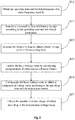
Fig. 2 shows a flow diagram of a preferred embodiment of a method for measuring the quantity of electric charge of battery of mobile communication terminal equipment according to an embodiments of the present invention; -
Fig. 3 shows a schematic diagram of the system for measuring the quantity of electric charge of battery of mobile communication terminal equipment according to an embodiments of the present invention; -
Fig. 4 shows a schematic diagram of a system with one processor for measuring the quantity of electric charge of battery of mobile communication terminal equipment according to an embodiments of the present invention; and -
Fig. 5 shows a schematic diagram of a system with two processors for measuring the quantity of electric charge of battery of mobile communication terminal equipment according to an embodiments of the present invention. - A clear and complete description of the technical solutions in the present invention will be given below, in conjunction with the accompanying drawings in the embodiments of the present invention. Apparently, the embodiments described below are a part, but not all, of the embodiments of the present invention. All of other embodiments, obtained by those of ordinary skill in the art based on the embodiments of the present invention without any creative effort, fall into the protection scope of the present invention.
- In the description of the present invention, it needs to be noted that, the terms such as "center", "above", "below", "left", "right", "vertical", "horizontal", "outside" refer to the orientation or position relation based on the illustration of the drawings, and merely for facilitating and simplifying the description of the present invention, but not indicating or implying that the apparatus or components must have a specific orientation, or a specific configuration and operation. Thus, it should be understood as a limitation to the present invention. In addition, the terms such as "first", "second", "third" are merely for the purpose of description, but should not be understood as an indication or implication of relative importance.
- In the description of the present invention, it needs to be noted that, unless specifically defined or restricted otherwise, terms "mount", "interconnect", "connect" should be broadly construed, for example, they may be fixed connection or detachable connection or integral connection; they may be mechanical connection or electrical connection; they may be direct connection, or indirect connection via an intermediate medium, or internal communication between two units; they may be wireless connection or wired connection. For those skilled in the art, the specific meaning of the aforementioned terms in the present invention can be understood according to specific situations thereof.
- Furthermore, the technical features which the embodiments of the present invention provided bellow refer to can be combined with each other as long as no conflict is constituted.
- Compared with a conventional terminal equipment, a mobile communication terminal has a radio frequency module, which is a prominent characteristic thereof. The module is large current and high power consumption module, and the starting or stopping of working of the module may cause a large fluctuation of battery voltage, having impact on the accuracy of measurement of quantity of electric charge of battery, thus, there is a need of making a compensation to battery voltage measured by the voltage measuring module in the mobile communication equipment, so as to ensure the accuracy of estimation of quantity of electric charge of battery according to the relation curve between the quantity of electric charge of battery and the battery voltage. In this context, the mobile communication terminal equipments include, but are not limited to, a cell phone, an interphone, a tablet computer, a lap top and etc.
- In order to accurately measure the quantity of electric charge of battery of mobile communication terminal equipment, embodiments of the present invention provide a method for measuring the quantity of electric charge of battery of mobile communication terminal equipment, and as shown in
Fig. 1 , the method includes the following steps: - S11: obtaining an operating state and related parameters of a radio frequency module. The operating state and the related parameters of the radio frequency module can be obtained through a micro-processor of the mobile communication terminal equipment. Generally, the radio frequency module may be a radio frequency transceiver consisting of a receiving unit and a transmitting unit which are independent with respect to each other. For a radio frequency transceiver, the operating state needed to be obtained includes an operating state STX of the transmitting unit of the radio frequency transceiver, namely in an activated state or an idle state, and an operating state SRX of the receiving unit, namely in an activated state or an idle state; and the related parameters needed to be obtained include a transmitting start time tTX, a transmitting duration DTX and a transmitting power PTX of the transmitting unit in each transmitting time slot, and a receiving start time tRX, a receiving duration DRX and a receive gain GRX of the receiving unit in each receiving time slot. Certainly, for some mobile communication terminal equipment, the radio frequency module may only have a transmitting unit or a receiving unit, and in this case, only the operating state and the related parameters of the transmitting unit or the receiving unit are obtained.
- S12: determining a measuring time tVM of a battery voltage according to the operating state and the related parameters of the radio frequency module. In order to compensate for the influence of the radio frequency module on the fluctuation of the battery voltage, the battery voltage needs to be measured when the radio frequency module is in operating state. In order to make the measurement result more accurate, as a preferred implementation scheme, the measuring time tVM is selected to be the midpoint of the operating time period of the radio frequency module, and at this time, the influence of the radio frequency module on the fluctuation of the battery voltage is most stable. Certainly, the measuring time selected to be earlier or later is feasible as long as it is within the operating time period of the radio frequency module.
- S13: measuring the battery voltage at the measuring time tVM to obtain a basic voltage value V0.
- S14: compensating the basic voltage value V0 according to the operating state and the related parameters of the radio frequency module to obtain a compensated voltage value VC.
- S15: obtaining the quantity of electric charge of battery according to the compensated voltage value. This step is the same as a conventional voltage measurement method, namely the quantity of electric charge of battery QC=f(VC) is calculated according to the obtained voltage value and the relation curve Q=f(V) between the quantity of electric charge of battery and the battery voltage.
- According to a method for measuring the quantity of electric charge of battery of the mobile communication terminal equipment, provided by the embodiments of the present invention, a measuring time of the battery voltage is determined according to the operating state and the related parameters of the radio frequency module, a basic voltage value is obtained by measuring at the measuring time, and a compensated voltage value is obtained according to the operating state and the related parameters of the radio frequency module to compensate the influence of the radio frequency module on the fluctuation of the battery voltage, so that the quantity of electric charge of battery of the mobile communication terminal equipment can be accurately obtained.
-
Fig. 2 shows a preferred embodiment of the method for measuring the quantity of electric charge of battery of the mobile communication terminal equipment according to the embodiments of the present invention, and in comparison with the method for measuring the quantity of electric charge of battery of the mobile communication terminal equipment inFig. 1 , S16: updating the basic voltage value according to conventional influence factors is added between S13 and S14 of the method. - In this step, any method for measuring the quantity of electric charge of battery of common terminal equipment in the prior art may be adopted to compensate for the influences of the factors such as an environment temperature, battery aging, backlight intensity, processor frequency on the battery voltage. The mobile communication terminal equipment also has power consuming equipment such as a display backlight, a central processing unit (CPU), a graphics processing unit (GPU) as those in the common terminal equipment, and the power consuming equipment and the factors including the environment temperature, battery aging and the like will also cause fluctuation to the battery voltage of the mobile communication terminal equipment, therefore, the influences of these factors on the battery voltage are compensated in the present embodiment, and the quantity of electric charge of battery of the mobile communication terminal equipment can be measured more accurately.
- Hereinafter, the steps of determining the measuring time of the battery voltage and compensating the basic voltage value are further described in detail by taking that the radio frequency is a radio frequency transceiver as an example.
- The step of determining the measuring time of the battery voltage may be divided into the following four conditions:
- 1) when the operating state STX of the transmitting unit of the radio frequency transceiver, received by the microprocessor, represents that the transmitting unit of the radio frequency transceiver is ready to transmit a signal, the microprocessor calculates the measuring time tVM of the battery voltage for each transmitting time slot respectively, where tTX<tVM<tTX+DTX, namely the measuring time tVM is within the operating time period of the radio frequency module, and preferably, tVM=tTX+DTX/2, namely the measuring time tVM is the midpoint of the operating time period of the transmitting module of the radio frequency module.
- 2) when the operating state SRX of the receiving unit of the radio frequency transceiver, received by the microprocessor, represents that the receiving unit of the radio frequency transceiver is ready to receive a signal, the microprocessor calculates the measuring time tVM of the battery voltage for each transmitting time slot respectively, where tRX<tVM<tRX+DRX, namely the measuring time tVM is within the operating time period of the radio frequency module, and preferably, tVM=tRX+DRX/2, namely the measuring time tVM is the midpoint of the operating time period of the receiving module of the radio frequency module.
- 3) when the operating states STX and SRX of the radio frequency transceiver, received by the microprocessor, represent that the transmitting unit and the receiving unit of the radio frequency transceiver are ready to transmit and receive signals at the same time, the microprocessor calculates a first measuring time tVM1 of the battery voltage for each transmitting time slot respectively, calculates a second measuring time tVM2 of the battery voltage for each transmitting time slot respectively, determines the time order of the first measuring time tVM1 and the second measuring time tVM2, and takes the earlier one of them as the measuring time of the battery voltage.
- 4) when the operating states STX and SRX of the radio frequency transceiver, received by the microprocessor, represent that the radio frequency transceiver does not have actions of transmitting and receiving signals, at that moment, the radio frequency transceiver is in an idle state and is very low in power consuming, the influence on the fluctuation of the battery voltage can be ignored, and in this case, the method for measuring the quantity of electric charge of battery is the same as that of a common terminal equipment in the prior art.
- Correspondingly, the step of compensating the basic voltage value may also be divided into the following four conditions:
- 1) when the basic voltage value V0 is obtained when the transmitting unit of the radio frequency transceiver is in operation, VC=V0+ΔVTX(PTX),where ΔVTX(PTX) represents a compensation voltage related to a transmitting power PTX, and preferably a relation table showing that ΔVTX corresponds to PTX can be pre-stored in a memory of the mobile communication terminal equipment, so that the compensation voltage can be obtained very easily in use by searching the table.
- 2) when the basic voltage value V0 is obtained when the receiving unit of the radio frequency transceiver is in operation, VC=V0+ΔVRX(GRX),where ΔVRX(GRX) represents a compensation voltage related to a receive gain GRX, and in the same way, preferably a relation table showing that ΔVRX corresponds to GRX can be pre-stored in a memory of the mobile communication terminal equipment, so that the compensation voltage can be obtained very easily in use by searching the table.
- 3) when the basic voltage value V0 is obtained when the transmitting unit and the receiving unit of the radio frequency transceiver are in operation, VC=V0+ΔVTX(PTX)+ΔVRX(GRX), where ΔVTX(PTX) represents a compensation voltage related to a transmitting power PTX, ΔVRX(GRX) represents a compensation voltage related to a receive gain GRX, and in the same way, preferably a relation table showing that ΔVTX corresponds to PTX and ΔVRX corresponds to GRX can be pre-stored in a memory of the mobile communication terminal equipment, so that the compensation voltage can be obtained very easily in use by searching the table.
- 4) when the basic voltage value V0 is obtained when both the transmitting unit and the receiving unit of the radio frequency transceiver are not in operation, at that moment, the radio frequency transceiver is in an idle state and is very low in power consumption, the influence on the fluctuation of the battery voltage can be ignored, and in this case, the basic voltage value V0 does not need to be subjected to compensation of the factor of the radio frequency transceiver, namely VC=V0.
- Referring to
Fig. 3 , the embodiments of the present invention also provides a system for measuring quantity of electric charge of battery of mobile communication terminal equipment, including: - a
parameter obtaining unit 11, for obtaining an operating state and related parameters of a radio frequency module; - a measuring
time determining unit 12, for determining a measuring time of a battery voltage according to the operating state and the related parameters; - a measuring
unit 13, for measuring the battery voltage to obtain a basic voltage value at the measuring time; - a compensating
unit 14, for compensating the basic voltage value to obtain a compensated voltage value according to the operating state and the related parameters; and - a quantity of electric charge of
battery obtaining unit 15, for obtaining the quantity of electric charge of battery according to the compensated voltage value. - The further detailed description of each of the units are the same as the previous embodiment, and is not mentioned herein. According to the system for measuring the quantity of electric charge of battery of the mobile communication terminal equipment, provided by embodiments of the present invention, a measuring time of the battery voltage is determined according to the operating state and the related parameters of the radio frequency module, a basic voltage value is obtained by measuring at the measuring time, and a compensated voltage value is obtained according to the operating state and the related parameters of the radio frequency module to compensate the influence of the radio frequency module on the fluctuation of the battery voltage, so that the quantity of electric charge of battery of the mobile communication terminal equipment can be accurately obtained.
- As a preferred embodiment, the system for measuring quantity of electric charge of battery of mobile communication terminal equipment also includes an updating
unit 16, for, between measuring the battery voltage by the measuringunit 13 to obtain a basic voltage value and compensating the basic voltage value by the compensatingunit 14 to obtain a compensated voltage value, updating the basic voltage value according to conventional influence factors. - By adaptation of the updating
unit 16, it is able to compensate the fluctuation of the quantity of electric charge of battery caused by the factors such the display backlight, a central processing unit (CPU), a graphics processing unit (GPU) as those in the common terminal equipment, and the power consuming equipment and other factors including the environment temperature, battery aging and the like, so that the quantity of electric charge of battery of the mobile communication terminal equipment can be measured more accurately. - The system for measuring quantity of electric charge of battery of mobile communication terminal equipment of the following embodiment of the present invention is further described in detail, wherein, the radio frequency module of this embodiment is a radio frequency transceiver.
- As a preferred embodiment, the measuring
time determining unit 12 includes: - a first determining unit, for, when the operating state indicates that a transmitting unit of the radio frequency transceiver is ready to transmit a signal, calculating the measuring time tVM (tTX<tVM<tTX+DTX) of the battery voltage for each transmitting time slot respectively, wherein tTX represents the transmitting start time of each transmitting time slot, and DTX represents a transmitting duration;
- a second determining unit, for, when the operating state indicates that a receiving unit of the radio frequency transceiver is ready to receive a signal, calculating the measuring time tVM (tRX<tVM<tTX+DRX) of the battery voltage for each transmitting time slot, wherein tRX represents the receiving start time of each receiving time slot, and DRX represents a receiving duration; and
- a third determining unit, for, when the operating state indicates that the transmitting unit and the receiving unit of the radio frequency transceiver are ready to respectively transmit and receive signals at the same time, calculating a first measuring time tVM1 (tTX<tVM1<tTX+DTX) of the battery voltage for each transmitting time slot calculating a second measuring time tVM2 (tRX<tVM2<tTX+DRX) of the battery voltage for each transmitting time slot, determining the time order of the first measuring time tVM1 and the second measuring time tVM2, and taking the earlier one of them as the measuring time of the battery voltage;
- a fourth determining unit, when the working state indicates the ratio frequency transceiver does not send or receive signal and the ratio frequency transceiver is in idle state, having low power consumption; the impact caused by the fluctuation of battery voltage can be ignored; in this circumstance, the way of measuring quantity of electric charge of battery is the same as that for general terminal equipment of prior arts.
- As a preferred embodiment, the compensating
unit 14 includes: - a first compensating subunit, for, when the basic voltage value is obtained under the condition that the transmitting unit of the radio frequency transceiver is in operation, determining the compensated voltage value VC=V0+ΔVTX(PTX);
- a second compensating subunit, for, when the basic voltage value is obtained under the condition that the receiving unit of the radio frequency transceiver is in operation, determining the compensated voltage value VC=V0+ΔVRX(GRX); and
- a third compensating subunit, for, when the basic voltage value is obtained under the condition that both of the transmitting unit and the receiving unit of the radio frequency transceiver are in operation, determining the compensated voltage value VC=V0+ΔVTX(PTX) +ΔVRX(GRX); wherein, V0 represents the basic voltage value, ΔVTX(PTX) represents a compensation voltage related to a transmitting frequency PTX of the radio frequency transceiver, and ΔVRX(GRX) represents a compensation voltage related to a receive gain GRX of the radio frequency transceiver;
- a fourth compensating unit, when the basic voltage value is obtained under the condition that both of the transmitting unit and the receiving unit of the radio frequency transceiver both are not in operation and the ratio transceiver is in idle state, having low power consumption, and the impact by fluctuation of battery voltage can be ignored, in this circumstance, there is no need of making a compensation to the basic voltage value V0 due to the factor of ratio frequency transceiver, i.e. Vc= V0
- The embodiment of the present invention further provides a system for measuring quantity of electric charge of battery of mobile communication terminal equipment, including: one or
more processors 200, amemory 100, one or more programs, stored in thememory 100, and when executed by the one ormore processors 200 perform the following steps of obtaining an operating state and related parameters of a radio frequency module; determining a measuring time of a battery voltage according to the operating state and the related parameters; measuring the battery voltage to obtain a basic voltage value at the measuring time; compensating the basic voltage value to obtain a compensated voltage value according to the operating state and the related parameters; and obtaining the quantity of electric charge of battery according to the compensated voltage value. The system may include oneprocessor 200 as illustrated inFig. 4 , or twoprocessors 200 as illustrated inFig. 5 . - In the system of this embodiment, preferably, the radio frequency module is a radio frequency transceiver.
- In the system of this embodiment, preferably, the step of determining the measuring time of the battery voltage according to the operating state and the related parameters includes: when the operating state indicates that a transmitting unit of the radio frequency transceiver is ready to transmit a signal, calculating the measuring time tVM (tTX<tVM<tTX+DTX) of the battery voltage for each transmitting time slot respectively, wherein tTX represents the transmitting start time of each transmitting time slot, and DTX represents a transmitting duration; when the operating state indicates that a receiving unit of the radio frequency transceiver is ready to receive a signal, calculating the measuring time tVM (tRX<tVM<tTX+DRX) of the battery voltage for each transmitting time slot, wherein tRX represents the receiving start time of each receiving time slot, and DRX represents a receiving duration; and when the operating state indicates that the transmitting unit and the receiving unit of the radio frequency transceiver are ready to respectively transmit and receive signals at the same time, calculating a first measuring time tVM1 (tTX<tVM1<tTX+DTX) of the battery voltage for each transmitting time slot calculating a second measuring time tVM2 (tRX<tVM2<tTX+DRX) of the battery voltage for each transmitting time slot, determining the time order of the first measuring time tVM1 and the second measuring time tVM2, and taking the earlier one of them as the measuring time of the battery voltage.
- In the system of this embodiment, preferably, the step of compensating the basic voltage value to obtain the compensated voltage value includes: when the basic voltage value is obtained under the condition that the transmitting unit of the radio frequency transceiver is in operation, determining the compensated voltage value VC=V0+ΔVTX(PTX); when the basic voltage value is obtained under the condition that the receiving unit of the radio frequency transceiver is in operation, determining the compensated voltage value VC=V0+ΔVRX(GRX); and when the basic voltage value is obtained under the condition that both of the transmitting unit and the receiving unit of the radio frequency transceiver are in operation, determining the compensated voltage value VC=V0+ΔVTX(PTX) +ΔVRX(GRX), wherein V0 represents the basic voltage value, ΔVTX(PTX) represents a compensation voltage related to a transmitting frequency PTX of the radio frequency transceiver, and ΔVRX(GRX) represents a compensation voltage related to a receive gain GRX of the radio frequency transceiver.
- In the system of this embodiment, preferably, between the step of measuring the battery voltage to obtain a basic voltage value and the step of compensating the basic voltage value to obtain a compensated voltage value, the programs further perform the step of updating the basic voltage value according to conventional influence factors.
- It should be appreciated by those skilled in the art that the embodiments of the present invention may be provided as methods, devices or computer program products. Therefore, the present invention may adopt the form of a complete hardware embodiment, a complete software embodiment or an embodiment of software and hardware in combination. Moreover, the present invention may adopt the form of a computer program product implemented on one or more computer-useable storage media (including but not limited to a magnetic disk memory, a CD-ROM, an optic memory, and the like) containing computer-usable program codes.
- The present invention is described with reference to flow charts and/or block diagrams of the methods, devices (systems) and computer program products according to the embodiments of the present invention. It should be understood that each flow step and/or block in the flow charts and/or block diagrams as well as combination of flow steps and/or blocks in the flow charts and/or block diagrams may be implemented by computer program instructions. These computer program instructions may be loaded onto a general computer, a dedicated computer, an embedded processor or a processor of other programmable data processing devices to produce a machine, so that a device for achieving functions designated in one or more flow steps of the flow charts and/or in one or more blocks of the block diagrams is produced by means of the instructions executed by the computer or the processor of other programmable data processing devices.
- These computer program instructions may also be stored in a computer-readable memory capable of guiding the computer or other programmable data processing devices to work in a specific mode, so as to produce a manufactured product including an instruction device by means of the instructions stored in the computer-readable memory, and the instruction device implements the functions designated in one or more flow steps of the flow charts and/or in one or more blocks of the block diagrams.
- These computer program instructions may also be loaded onto a computer or other programmable data processing devices, so that a series of operation steps are executed on the computer or other programmable devices to produce processing implemented by the computer, and the instructions executed on the computer or other programmable data processing devices provide steps for implementing the functions designated in one or more flow steps of the flow charts and/or in one or more blocks of the block diagrams.
- Obviously, it should be noted that the above embodiments are merely used for illustrating rather than limiting the technical solutions of the present application; although the present application is illustrated in detail with reference to the aforementioned embodiments, it should be understood by those of ordinary skill in the art that modifications may still be made on the technical solutions disclosed in the aforementioned respective embodiments, or equivalent substitutions may be made to part of technical characteristics thereof; and these modifications or substitutions shall not make the nature of the corresponding technical solutions depart from the spirit and scope of the technical solutions of the respective embodiments of the present disclosure.
Claims (15)
- A method for measuring quantity of electric charge of battery of mobile communication terminal equipment, characterized in comprising:obtaining an operating state and related parameters of a radio frequency module;determining a measuring time of a battery voltage according to the operating state and the related parameters;measuring the battery voltage to obtain a basic voltage value at the measuring time;compensating the basic voltage value to obtain a compensated voltage value according to the operating state and the related parameters; andobtaining the quantity of electric charge of battery according to the compensated voltage value.
- The method according to claim 1, characterized in that the radio frequency module is a radio frequency transceiver.
- The method according to claim 2, characterized in that the step of determining the measuring time of the battery voltage according to the operating state and the related parameters comprises:when the operating state indicates that a transmitting unit of the radio frequency transceiver is ready to transmit a signal, calculating the measuring time tVM (tTX<tVM<tTX+DTX) of the battery voltage for each transmitting time slot respectively, wherein tTX represents the transmitting start time of each transmitting time slot, and DTX represents a transmitting duration;when the operating state indicates that a receiving unit of the radio frequency transceiver is ready to receive a signal, calculating the measuring time tVM (tRX<tVM<tTX+DRX) of the battery voltage for each transmitting time slot, wherein tRX represents the receiving start time of each receiving time slot, and DRX represents a receiving duration; andwhen the operating state indicates that the transmitting unit and the receiving unit of the radio frequency transceiver are ready to respectively transmit and receive signals at the same time, calculating a first measuring time tVM1 (tTX<tVM1<tTX+DTX) of the battery voltage for each transmitting time slot , calculating a second measuring time tVM2 (tRX<tVM2<tTX+DRX) of the battery voltage for each transmitting time slot, determining the time order of the first measuring time tVM1 and the second measuring time tVM2, and taking the earlier one of them as the measuring time of the battery voltage.
- The method according to claim 2 or 3, characterized in that the step of compensating the basic voltage value to obtain the compensated voltage value comprises:when the basic voltage value is obtained under the condition that the transmitting unit of the radio frequency transceiver is in operation, determining the compensated voltage value VC=V0+ΔVTX(PTX);when the basic voltage value is obtained under the condition that the receiving unit of the radio frequency transceiver is in operation, determining the compensated voltage value VC=V0+ΔVRX(GRX); andwhen the basic voltage value is obtained under the condition that both of the transmitting unit and the receiving unit of the radio frequency transceiver are in operation, determining the compensated voltage value VC=V0+ΔVTX(PTX) +ΔVRX(GRX),wherein V0 represents the basic voltage value, ΔVTX(PTX) represents a compensation voltage related to a transmitting frequency PTX of the radio frequency transceiver, and ΔVRX(GRX) represents a compensation voltage related to a receive gain GRX of the radio frequency transceiver.
- The method according to any one of claims 1-4, characterized in that between the step of measuring the battery voltage to obtain a basic voltage value and the step of compensating the basic voltage value to obtain a compensated voltage value, the method further comprises:updating the basic voltage value according to conventional influence factors.
- A system for measuring quantity of electric charge of battery of mobile communication terminal equipment, characterized in comprising:a parameter obtaining unit, for obtaining an operating state and related parameters of a radio frequency module;a measuring time determining unit, for determining a measuring time of a battery voltage according to the operating state and the related parameters;a measuring unit, for measuring the battery voltage to obtain a basic voltage value at the measuring time;a compensating unit, for compensating the basic voltage value to obtain a compensated voltage value according to the operating state and the related parameters; anda quantity of electric charge of battery obtaining unit, for obtaining the quantity of electric charge of battery according to the compensated voltage value.
- The system according to claim 6, characterized in that the radio frequency module is a radio frequency transceiver.
- The system according to claim 7, characterized in that the measuring time determining unit comprises:a first determining unit, for, when the operating state indicates that a transmitting unit of the radio frequency transceiver is ready to transmit a signal, calculating the measuring time tVM (tTX<tVM<tTX+DTX) of the battery voltage for each transmitting time slot respectively, wherein tTX represents the transmitting start time of each transmitting time slot, and DTX represents a transmitting duration;a second determining unit, for, when the operating state indicates that a receiving unit of the radio frequency transceiver is ready to receive a signal, calculating the measuring time tVM (tRX<tVM<tTX+DRX) of the battery voltage for each transmitting time slot, wherein tRX represents the receiving start time of each receiving time slot, and DRX represents a receiving duration; anda third determining unit, for, when the operating state indicates that the transmitting unit and the receiving unit of the radio frequency transceiver are ready to respectively transmit and receive signals at the same time, calculating a first measuring time tVM1 (tTX<tVM1<tTX+DTX) of the battery voltage for each transmitting time slot calculating a second measuring time tVM2 (tRX<tVM2<tTX+DRX) of the battery voltage for each transmitting time slot, determining the time order of the first measuring time tVM1 and the second measuring time tVM2, and taking the earlier one of them as the measuring time of the battery voltage.
- The system according to claim 7 or 8, characterized in that compensating unit comprises:a first compensating subunit, for, when the basic voltage value is obtained under the condition that the transmitting unit of the radio frequency transceiver is in operation, determining the compensated voltage value VC=V0+ΔVTX(PTX);a second compensating subunit, for, when the basic voltage value is obtained under the condition that the receiving unit of the radio frequency transceiver is in operation, determining the compensated voltage value VC=V0+ΔVRX(GRX); anda third compensating subunit, for, when the basic voltage value is obtained under the condition that both of the transmitting unit and the receiving unit of the radio frequency transceiver are in operation, determining the compensated voltage value VC=V0+ΔVTX(PTX) +ΔVRX(GRX),wherein, V0 represents the basic voltage value, ΔVTX(PTX) represents a compensation voltage related to a transmitting frequency PTX of the radio frequency transceiver, and ΔVRX(GRX) represents a compensation voltage related to a receive gain GRX of the radio frequency transceiver.
- The system according to any one of claims 6-9, characterized in that an updating unit, for, between the step of measuring the battery voltage to obtain a basic voltage value and the step of compensating the basic voltage value to obtain a compensated voltage value, updating the basic voltage value according to conventional influence factors.
- A system for measuring quantity of electric charge of battery of mobile communication terminal equipment, characterized in comprising one or more processors, a memory, one or more programs, stored in the memory, and when executed by the one or more processors perform the following steps of
obtaining an operating state and related parameters of a radio frequency module;
determining a measuring time of a battery voltage according to the operating state and the related parameters;
measuring the battery voltage to obtain a basic voltage value at the measuring time;
compensating the basic voltage value to obtain a compensated voltage value according to the operating state and the related parameters; and
obtaining the quantity of electric charge of battery according to the compensated voltage value. - The system according to claim 11, characterized in that the radio frequency module is a radio frequency transceiver.
- The system according to claim 12, characterized in that the step of determining the measuring time of the battery voltage according to the operating state and the related parameters comprises:when the operating state indicates that a transmitting unit of the radio frequency transceiver is ready to transmit a signal, calculating the measuring time tVM (tTX<tVM<tTX+DTX) of the battery voltage for each transmitting time slot respectively, wherein tTX represents the transmitting start time of each transmitting time slot, and DTX represents a transmitting duration;when the operating state indicates that a receiving unit of the radio frequency transceiver is ready to receive a signal, calculating the measuring time tVM (tRX<tVM<tTX+DRX) of the battery voltage for each transmitting time slot, wherein tRX represents the receiving start time of each receiving time slot, and DRX represents a receiving duration; andwhen the operating state indicates that the transmitting unit and the receiving unit of the radio frequency transceiver are ready to respectively transmit and receive signals at the same time, calculating a first measuring time tVM1 (tTX<tVM1<tTX+DTX) of the battery voltage for each transmitting time slot calculating a second measuring time tVM2 (tRX<tVM2<tTX+DRX) of the battery voltage for each transmitting time slot, determining the time order of the first measuring time tVM1 and the second measuring time tVM2, and taking the earlier one of them as the measuring time of the battery voltage.
- The system according to claim 12 or 13, characterized in that the step of compensating the basic voltage value to obtain the compensated voltage value comprises:when the basic voltage value is obtained under the condition that the transmitting unit of the radio frequency transceiver is in operation, determining the compensated voltage value VC=V0+ΔVTX(PTX);when the basic voltage value is obtained under the condition that the receiving unit of the radio frequency transceiver is in operation, determining the compensated voltage value VC=V0+ΔVRX(GRX); andwhen the basic voltage value is obtained under the condition that both of the transmitting unit and the receiving unit of the radio frequency transceiver are in operation, determining the compensated voltage value VC=V0+ΔVTX(PTX) +ΔVRX(GRX),wherein V0 represents the basic voltage value, ΔVTX(PTX) represents a compensation voltage related to a transmitting frequency PTX of the radio frequency transceiver, and ΔVRX(GRX) represents a compensation voltage related to a receive gain GRX of the radio frequency transceiver.
- The system according to any one of claims 11-15, characterized in that between the step of measuring the battery voltage to obtain a basic voltage value and the step of compensating the basic voltage value to obtain a compensated voltage value, the programs further perform the step of:updating the basic voltage value according to conventional influence factors.
Applications Claiming Priority (2)
| Application Number | Priority Date | Filing Date | Title |
|---|---|---|---|
| CN201511023851.9A CN105866688A (en) | 2015-12-30 | 2015-12-30 | Method of measuring mobile communication terminal equipment cell capacity and system thereof |
| PCT/CN2016/088318 WO2017113675A1 (en) | 2015-12-30 | 2016-07-04 | Method and system for measuring battery power of mobile communication terminal device |
Publications (2)
| Publication Number | Publication Date |
|---|---|
| EP3211441A1 true EP3211441A1 (en) | 2017-08-30 |
| EP3211441A4 EP3211441A4 (en) | 2018-01-24 |
Family
ID=56624447
Family Applications (1)
| Application Number | Title | Priority Date | Filing Date |
|---|---|---|---|
| EP16777886.9A Withdrawn EP3211441A4 (en) | 2015-12-30 | 2016-07-04 | Method and system for measuring battery power of mobile communication terminal device |
Country Status (4)
| Country | Link |
|---|---|
| US (1) | US20170195067A1 (en) |
| EP (1) | EP3211441A4 (en) |
| CN (1) | CN105866688A (en) |
| WO (1) | WO2017113675A1 (en) |
Families Citing this family (9)
| Publication number | Priority date | Publication date | Assignee | Title |
|---|---|---|---|---|
| CN106603874B (en) * | 2017-02-27 | 2019-03-05 | 维沃移动通信有限公司 | A method for displaying power level of a mobile terminal and a mobile terminal |
| CN112292604B (en) * | 2018-10-31 | 2021-12-21 | 华为技术有限公司 | Battery voltage compensation method and device and terminal equipment |
| CN111929589B (en) * | 2020-07-21 | 2023-05-16 | 广州威拓电子科技有限公司 | Method, device, terminal and storage medium for outputting electric quantity value of disposable battery |
| CN112782596A (en) * | 2020-12-07 | 2021-05-11 | 深圳市新国都支付技术有限公司 | Battery electric quantity calculation method, electronic device and storage medium |
| CN112887472B (en) * | 2021-01-25 | 2024-08-09 | 惠州Tcl移动通信有限公司 | A battery identification method, a mobile terminal and a computer-readable storage medium |
| WO2023097516A1 (en) * | 2021-11-30 | 2023-06-08 | 华为技术有限公司 | Communication device, voltage measurement method and computer-readable storage medium |
| CN114521009B (en) * | 2022-04-21 | 2022-09-16 | 南京大鱼半导体有限公司 | Power control method and device based on power supply voltage and baseband chip |
| CN116435631B (en) * | 2023-03-16 | 2024-07-30 | 长沙熙臻电子科技有限公司 | Button cell low-power alarming method |
| CN116679821B (en) * | 2023-08-04 | 2024-03-22 | 荣耀终端有限公司 | Voltage adjustment method and electronic equipment |
Family Cites Families (18)
| Publication number | Priority date | Publication date | Assignee | Title |
|---|---|---|---|---|
| JP3902365B2 (en) * | 1999-10-28 | 2007-04-04 | 三洋電機株式会社 | Battery level judgment device |
| JP2004138588A (en) * | 2002-10-21 | 2004-05-13 | Matsushita Electric Ind Co Ltd | Battery level display device and portable terminal |
| JP4405232B2 (en) * | 2003-10-24 | 2010-01-27 | ソニー・エリクソン・モバイルコミュニケーションズ株式会社 | Voltage detection method and apparatus, and electronic apparatus |
| CN1641372A (en) * | 2004-01-02 | 2005-07-20 | 明基电通股份有限公司 | Compensation device and method for battery power of mobile electronic device |
| GB2411055B (en) * | 2004-02-10 | 2006-05-17 | Sendo Int Ltd | Wireless communication unit, battery and battery charge determination mechanism |
| CN1889736A (en) * | 2006-08-08 | 2007-01-03 | 北京天碁科技有限公司 | Method for measuring mobile communication terminal battery electricity quantity |
| CN101728588B (en) * | 2008-10-10 | 2012-01-25 | 鸿富锦精密工业(深圳)有限公司 | Wireless communication terminal and method for determining battery electric quantity thereof |
| JP5487604B2 (en) * | 2008-11-30 | 2014-05-07 | 日本電気株式会社 | Battery monitoring method, portable electronic device, program |
| CN101806867A (en) * | 2010-03-12 | 2010-08-18 | 中兴通讯股份有限公司 | Method and device for measuring electric quantity of mobile phone battery |
| CN102918409B (en) * | 2010-05-27 | 2016-05-11 | 诺基亚技术有限公司 | Method of estimating remaining charge of battery of portable device |
| CN102540080B (en) * | 2010-12-27 | 2015-05-20 | 联芯科技有限公司 | Method for detecting voltage of battery (BAVT), and terminal equipment |
| US9182428B2 (en) * | 2011-04-29 | 2015-11-10 | Linear Technology Corporation | Switched capacitance voltage differential sensing circuit with near infinite input impedance |
| CN102375127B (en) * | 2011-11-11 | 2014-01-08 | 深圳市中兴移动通信有限公司 | Method for displaying residual battery electricity quantity of mobile terminal |
| CN103176132B (en) * | 2011-12-22 | 2015-08-12 | 联芯科技有限公司 | The evaluation method of battery electric quantity and terminal device |
| JP6115219B2 (en) * | 2013-03-18 | 2017-04-19 | 富士通株式会社 | COMMUNICATION TERMINAL DEVICE, BATTERY REMAINING PRESENTATION METHOD, AND PROGRAM |
| CN103472400B (en) * | 2013-09-06 | 2016-05-04 | 广东欧珀移动通信有限公司 | A kind of acquisition methods of battery capacity of mobile terminal and system |
| CN103792490B (en) * | 2013-11-22 | 2016-08-17 | 广州视源电子科技股份有限公司 | Method for measuring and calculating battery capacity of system |
| CN104714185B (en) * | 2015-03-12 | 2017-12-19 | 惠州Tcl移动通信有限公司 | A kind of battery electric quantity auto-correction method and system based on mobile terminal |
-
2015
- 2015-12-30 CN CN201511023851.9A patent/CN105866688A/en active Pending
-
2016
- 2016-07-04 WO PCT/CN2016/088318 patent/WO2017113675A1/en not_active Ceased
- 2016-07-04 EP EP16777886.9A patent/EP3211441A4/en not_active Withdrawn
- 2016-08-22 US US15/243,354 patent/US20170195067A1/en not_active Abandoned
Also Published As
| Publication number | Publication date |
|---|---|
| CN105866688A (en) | 2016-08-17 |
| WO2017113675A1 (en) | 2017-07-06 |
| US20170195067A1 (en) | 2017-07-06 |
| EP3211441A4 (en) | 2018-01-24 |
Similar Documents
| Publication | Publication Date | Title |
|---|---|---|
| EP3211441A1 (en) | Method and system for measuring battery power of mobile communication terminal device | |
| US10581256B2 (en) | Control method and electronic device based on battery leakage state | |
| EP3340422B1 (en) | Charging control method for battery based on time and electronic device supporting the same | |
| US9651628B2 (en) | Method and apparatus for determining a capacity of a battery | |
| EP2851700B1 (en) | Method and terminal for displaying capacity of battery | |
| US9146261B2 (en) | Electronic device and method of electronic device for determining power source device | |
| US8400116B2 (en) | Method and apparatus for calculating power-off duration time and state of charging of battery | |
| US7987298B2 (en) | System and method for detecting the status of a universal serial bus port of a mobile phone | |
| US20140156209A1 (en) | Devices with battery remaining capacity estimating functions | |
| US10644515B2 (en) | Information processing system, information processing device, operation device, and power supply method | |
| US20230217148A1 (en) | Charging method and system, charging box, and bluetooth earphones | |
| WO2016000543A1 (en) | Method, device and mobile terminal for detecting abnormal cpu occupancy rate of app | |
| US20090197651A1 (en) | Wireless communication terminal and battery capacitance measuring method | |
| CN110687458A (en) | Terminal battery electric quantity determination method and device | |
| KR20210007698A (en) | Electronic device including battery and method for controlling charging of battery thereof | |
| KR20260014000A (en) | Method, device, medium and system for shift control of dimmable elements | |
| CN110861533A (en) | Electric vehicle SOH estimation method and device and storage medium | |
| US20150340893A1 (en) | Portable device and method for controlling charging current thereof | |
| US20180040925A1 (en) | Charging method for adjusting charging current and mobile terminal | |
| US20160306013A1 (en) | Determining battery state of charge using an open circuit voltage measured prior to a device operation stage | |
| US20150309122A1 (en) | Battery state estimation method | |
| US20160079775A1 (en) | Charging Current Setting Method and Charging Module | |
| US10514422B2 (en) | Aspects for determining charging capacity of a battery | |
| CN116317031A (en) | Method, device, equipment and storage medium for adjusting charging current of power exchange cabinet | |
| WO2017094311A1 (en) | Power management integrated circuit, electronic device, and method for controlling power management integrated circuit |
Legal Events
| Date | Code | Title | Description |
|---|---|---|---|
| PUAI | Public reference made under article 153(3) epc to a published international application that has entered the european phase |
Free format text: ORIGINAL CODE: 0009012 |
|
| 17P | Request for examination filed |
Effective date: 20161017 |
|
| AK | Designated contracting states |
Kind code of ref document: A1 Designated state(s): AL AT BE BG CH CY CZ DE DK EE ES FI FR GB GR HR HU IE IS IT LI LT LU LV MC MK MT NL NO PL PT RO RS SE SI SK SM TR |
|
| AX | Request for extension of the european patent |
Extension state: BA ME |
|
| RIC1 | Information provided on ipc code assigned before grant |
Ipc: G01R 31/36 20060101AFI20170811BHEP |
|
| RIN1 | Information on inventor provided before grant (corrected) |
Inventor name: ZHOU, ZHONGQIAN |
|
| R17P | Request for examination filed (corrected) |
Effective date: 20161017 |
|
| A4 | Supplementary search report drawn up and despatched |
Effective date: 20180104 |
|
| RIC1 | Information provided on ipc code assigned before grant |
Ipc: G01R 31/36 20060101AFI20171220BHEP |
|
| STAA | Information on the status of an ep patent application or granted ep patent |
Free format text: STATUS: THE APPLICATION IS DEEMED TO BE WITHDRAWN |
|
| 18D | Application deemed to be withdrawn |
Effective date: 20180803 |