EP3211277A1 - Method and device for piston seal anti-rotation - Google Patents
Method and device for piston seal anti-rotation Download PDFInfo
- Publication number
- EP3211277A1 EP3211277A1 EP17157485.8A EP17157485A EP3211277A1 EP 3211277 A1 EP3211277 A1 EP 3211277A1 EP 17157485 A EP17157485 A EP 17157485A EP 3211277 A1 EP3211277 A1 EP 3211277A1
- Authority
- EP
- European Patent Office
- Prior art keywords
- retention block
- flange
- stem
- face
- support structure
- Prior art date
- Legal status (The legal status is an assumption and is not a legal conclusion. Google has not performed a legal analysis and makes no representation as to the accuracy of the status listed.)
- Granted
Links
Images



Classifications
-
- F—MECHANICAL ENGINEERING; LIGHTING; HEATING; WEAPONS; BLASTING
- F01—MACHINES OR ENGINES IN GENERAL; ENGINE PLANTS IN GENERAL; STEAM ENGINES
- F01D—NON-POSITIVE DISPLACEMENT MACHINES OR ENGINES, e.g. STEAM TURBINES
- F01D11/00—Preventing or minimising internal leakage of working-fluid, e.g. between stages
- F01D11/003—Preventing or minimising internal leakage of working-fluid, e.g. between stages by packing rings; Mechanical seals
-
- F—MECHANICAL ENGINEERING; LIGHTING; HEATING; WEAPONS; BLASTING
- F01—MACHINES OR ENGINES IN GENERAL; ENGINE PLANTS IN GENERAL; STEAM ENGINES
- F01D—NON-POSITIVE DISPLACEMENT MACHINES OR ENGINES, e.g. STEAM TURBINES
- F01D11/00—Preventing or minimising internal leakage of working-fluid, e.g. between stages
- F01D11/005—Sealing means between non relatively rotating elements
-
- F—MECHANICAL ENGINEERING; LIGHTING; HEATING; WEAPONS; BLASTING
- F01—MACHINES OR ENGINES IN GENERAL; ENGINE PLANTS IN GENERAL; STEAM ENGINES
- F01D—NON-POSITIVE DISPLACEMENT MACHINES OR ENGINES, e.g. STEAM TURBINES
- F01D25/00—Component parts, details, or accessories, not provided for in, or of interest apart from, other groups
- F01D25/24—Casings; Casing parts, e.g. diaphragms, casing fastenings
- F01D25/246—Fastening of diaphragms or stator-rings
-
- F—MECHANICAL ENGINEERING; LIGHTING; HEATING; WEAPONS; BLASTING
- F02—COMBUSTION ENGINES; HOT-GAS OR COMBUSTION-PRODUCT ENGINE PLANTS
- F02C—GAS-TURBINE PLANTS; AIR INTAKES FOR JET-PROPULSION PLANTS; CONTROLLING FUEL SUPPLY IN AIR-BREATHING JET-PROPULSION PLANTS
- F02C7/00—Features, components parts, details or accessories, not provided for in, or of interest apart form groups F02C1/00 - F02C6/00; Air intakes for jet-propulsion plants
- F02C7/28—Arrangement of seals
-
- F—MECHANICAL ENGINEERING; LIGHTING; HEATING; WEAPONS; BLASTING
- F16—ENGINEERING ELEMENTS AND UNITS; GENERAL MEASURES FOR PRODUCING AND MAINTAINING EFFECTIVE FUNCTIONING OF MACHINES OR INSTALLATIONS; THERMAL INSULATION IN GENERAL
- F16J—PISTONS; CYLINDERS; SEALINGS
- F16J15/00—Sealings
- F16J15/16—Sealings between relatively-moving surfaces
- F16J15/32—Sealings between relatively-moving surfaces with elastic sealings, e.g. O-rings
- F16J15/3268—Mounting of sealing rings
- F16J15/3272—Mounting of sealing rings the rings having a break or opening, e.g. to enable mounting on a shaft otherwise than from a shaft end
-
- F—MECHANICAL ENGINEERING; LIGHTING; HEATING; WEAPONS; BLASTING
- F16—ENGINEERING ELEMENTS AND UNITS; GENERAL MEASURES FOR PRODUCING AND MAINTAINING EFFECTIVE FUNCTIONING OF MACHINES OR INSTALLATIONS; THERMAL INSULATION IN GENERAL
- F16J—PISTONS; CYLINDERS; SEALINGS
- F16J9/00—Piston-rings, e.g. non-metallic piston-rings, seats therefor; Ring sealings of similar construction
- F16J9/12—Details
- F16J9/24—Members preventing rotation of rings in grooves
-
- F—MECHANICAL ENGINEERING; LIGHTING; HEATING; WEAPONS; BLASTING
- F05—INDEXING SCHEMES RELATING TO ENGINES OR PUMPS IN VARIOUS SUBCLASSES OF CLASSES F01-F04
- F05D—INDEXING SCHEME FOR ASPECTS RELATING TO NON-POSITIVE-DISPLACEMENT MACHINES OR ENGINES, GAS-TURBINES OR JET-PROPULSION PLANTS
- F05D2240/00—Components
- F05D2240/55—Seals
- F05D2240/58—Piston ring seals
-
- F—MECHANICAL ENGINEERING; LIGHTING; HEATING; WEAPONS; BLASTING
- F05—INDEXING SCHEMES RELATING TO ENGINES OR PUMPS IN VARIOUS SUBCLASSES OF CLASSES F01-F04
- F05D—INDEXING SCHEME FOR ASPECTS RELATING TO NON-POSITIVE-DISPLACEMENT MACHINES OR ENGINES, GAS-TURBINES OR JET-PROPULSION PLANTS
- F05D2260/00—Function
- F05D2260/30—Retaining components in desired mutual position
-
- F—MECHANICAL ENGINEERING; LIGHTING; HEATING; WEAPONS; BLASTING
- F05—INDEXING SCHEMES RELATING TO ENGINES OR PUMPS IN VARIOUS SUBCLASSES OF CLASSES F01-F04
- F05D—INDEXING SCHEME FOR ASPECTS RELATING TO NON-POSITIVE-DISPLACEMENT MACHINES OR ENGINES, GAS-TURBINES OR JET-PROPULSION PLANTS
- F05D2260/00—Function
- F05D2260/30—Retaining components in desired mutual position
- F05D2260/36—Retaining components in desired mutual position by a form fit connection, e.g. by interlocking
-
- Y—GENERAL TAGGING OF NEW TECHNOLOGICAL DEVELOPMENTS; GENERAL TAGGING OF CROSS-SECTIONAL TECHNOLOGIES SPANNING OVER SEVERAL SECTIONS OF THE IPC; TECHNICAL SUBJECTS COVERED BY FORMER USPC CROSS-REFERENCE ART COLLECTIONS [XRACs] AND DIGESTS
- Y02—TECHNOLOGIES OR APPLICATIONS FOR MITIGATION OR ADAPTATION AGAINST CLIMATE CHANGE
- Y02T—CLIMATE CHANGE MITIGATION TECHNOLOGIES RELATED TO TRANSPORTATION
- Y02T50/00—Aeronautics or air transport
- Y02T50/60—Efficient propulsion technologies, e.g. for aircraft
Definitions
- the present application relates generally to seal assemblies, and more particularly to split-ring piston seals.
- Piston seals can be used in a variety of applications to create a seal between fluids of different pressures and temperatures. Piston seals can exhibit significant wear (e.g., fretting can cause narrowing of seals, as well as shortening of split-ring seals) when allowed to rotate freely in a circumferential direction. Wear is not limited to applications involving the sealing of rotating components. Piston seals applied between static, non-rotating, structures, may also exhibit wear due to rotation.
- a method of limiting circumferential rotation of a split-ring seal for use in a gas turbine engine includes inserting a retention block through a slot in a flange of a support structure and into a groove configured to hold a split-ring seal, and engaging an end of a split-ring seal in the groove with a surface of the retention block.
- an anti-rotation device for limiting circumferential movement of a split-ring piston seal includes a retention block.
- the retention block includes a first side, a first face adjacent to the first side, a stem extending outward from the first side, and a boss extending outward from the first face.
- FIG. 1 is a quarter-sectional view of a gas turbine engine 20 that includes fan section 22, compressor section 24, combustor section 26 and turbine section 28.
- Alternative engines might include an augmenter section (not shown) among other systems or features.
- Fan section 22 drives air along bypass flow path B while compressor section 24 draws air in along core flow path C where air is compressed and communicated to combustor section 26.
- combustor section 26 air is mixed with fuel and ignited to generate a high pressure exhaust gas stream that expands through turbine section 28 where energy is extracted and utilized to drive fan section 22 and compressor section 24.
- turbofan gas turbine engine depicts a turbofan gas turbine engine
- the concepts described herein are not limited to use with turbofans as the teachings may be applied to other types of turbine engines; for example a turbine engine including a three-spool architecture in which three spools concentrically rotate about a common axis and where a low spool enables a low pressure turbine to drive a fan via a gearbox, an intermediate spool that enables an intermediate pressure turbine to drive a first compressor of the compressor section, and a high spool that enables a high pressure turbine to drive a high pressure compressor of the compressor section.
- the example engine 20 generally includes low speed spool 30 and high speed spool 32 mounted for rotation about an engine central longitudinal axis A relative to an engine static structure 36 via several bearing systems 38. It should be understood that various bearing systems 38 at various locations may alternatively or additionally be provided.
- Low speed spool 30 generally includes inner shaft 40 that connects fan 42 and low pressure (or first) compressor section 44 to low pressure (or first) turbine section 46.
- Inner shaft 40 drives fan 42 through a speed change device, such as geared architecture 48, to drive fan 42 at a lower speed than low speed spool 30.
- High-speed spool 32 includes outer shaft 50 that interconnects high pressure (or second) compressor section 52 and high pressure (or second) turbine section 54.
- Inner shaft 40 and outer shaft 50 are concentric and rotate via bearing systems 38 about engine central longitudinal axis A.
- Combustor 56 is arranged between high pressure compressor 52 and high pressure turbine 54.
- high pressure turbine 54 includes at least two stages to provide a double stage high pressure turbine 54.
- high pressure turbine 54 includes only a single stage.
- a "high pressure" compressor or turbine experiences a higher pressure than a corresponding "low pressure” compressor or turbine.
- the example low pressure turbine 46 has a pressure ratio that is greater than about 5.
- the pressure ratio of the example low pressure turbine 46 is measured prior to an inlet of low pressure turbine 46 as related to the pressure measured at the outlet of low pressure turbine 46 prior to an exhaust nozzle.
- Mid-turbine frame 57 of engine static structure 36 is arranged generally between high pressure turbine 54 and low pressure turbine 46.
- Mid-turbine frame 57 further supports bearing systems 38 in turbine section 28 as well as setting airflow entering low pressure turbine 46.
- the core airflow C is compressed by low pressure compressor 44 then by high pressure compressor 52 mixed with fuel and ignited in combustor 56 to produce high speed exhaust gases that are then expanded through high pressure turbine 54 and low pressure turbine 46.
- Mid-turbine frame 57 includes airfoils/vanes 59, which are in the core airflow path and function as an inlet guide vane for low pressure turbine 46. Utilizing vanes 59 of mid-turbine frame 57 as inlet guide vanes for low pressure turbine 46 decreases the length of low pressure turbine 46 without increasing the axial length of mid-turbine frame 57. Reducing or eliminating the number of vanes in low pressure turbine 46 shortens the axial length of turbine section 28. Thus, the compactness of gas turbine engine 20 is increased and a higher power density may be achieved.
- the disclosed gas turbine engine 20 in one example is a high-bypass geared aircraft engine.
- gas turbine engine 20 includes a bypass ratio greater than about six (6), with an example embodiment being greater than about ten (10).
- the example geared architecture 48 is an epicyclical gear train, such as a planetary gear system, star gear system or other known gear system, with a gear reduction ratio of greater than about 2.3.
- gas turbine engine 20 includes a bypass ratio greater than about ten (10:1) and the fan diameter is significantly larger than an outer diameter of low pressure compressor 44. It should be understood, however, that the above parameters are only exemplary of one embodiment of a gas turbine engine including a geared architecture and that the present disclosure is applicable to other gas turbine engines.
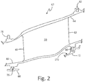
- FIG. 2 is a cross-sectional view of mid-turbine frame 57, which includes airfoils/vanes 59 (each having leading edge 60 and trailing edge 62), outer platform 64, inner platform 66, inner diameter forward seal support structure 68, inner diameter aft seal support structure 70, forward inner diameter seal 76 and outer diameter seal 78, aft inner diameter seal 80 and outer diameter seal 82.
- Seals 76, 78, 80, and 82 can each be split-ring piston seals. In the disclosed embodiment, seals 76, 80, and 82 can be biased outward, whereas spring 78 can be biased inward toward outer platform 64. As shown in FIG.
- forward inner seal 76 and aft inner seal 80 can be axially retained in support structures 68 and 70, respectively, and radially retained by inner platform 66, respectively.
- Seals 78 and 82 can also be axially and radially retained by adjacent structures, although not fully illustrated in FIG. 2 ). All seals (76, 78, 80, and 82) may exhibit substantial wear, including reduced thickness and length due to fretting, if allowed to freely rotate in a circumferential direction.
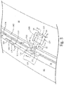
- FIGS. 3-5 show one embodiment of an anti-rotation seal retention feature and seal assembly used to limit circumferential movement of forward inner diameter seal 76.
- FIG. 3 is a perspective view of seal retention block 90.
- FIG. 4 is a cross-sectional view of seal retention block 90 taken along the 4-4 line of FIG. 3 .
- FIG. 5 is a cross-sectional view of seal retention block 90 taken along the 5-5 line of FIG. 3 .
- Seal retention block 90 can include first side 92, second side 94 located opposite first side 92, stem 96 extending outward from first side 92, first face 98, and second face 100, located opposite first face 98.
- First and second faces 98 and 100 can be inner and outer surfaces, respectively, each being located adjacent first and second sides 92 and 94, which can be arranged at opposite lateral sides of retention block 90.
- Stem 96 can have a height (h s ) equal to a height (h b ) of retention bock 90, extending from first face 98 to second face 100.
- Stem 96 can have a width (w s ) less than a width (w b ) of seal retention block 90 and can be substantially centered along first side 92.
- Support structure 68 can include flange 102, which can make up one of two walls 104 and 106, forming groove 108. Groove 108 can be configured to hold forward inner seal 76. Seal 76 can be a split ring seal having first end 110 and second end 112. First end 110 and second end 112 can each be reduced in thickness (t s ), such that each end 110 and 112 extends only a partial thickness of groove 108, extending from wall 104 to wall 106. While in the illustrated embodiment first and second ends 110 and 112 have equal thickness t s , first and second ends 110 and 112 can have different thicknesses. The reduced thickness (t s ) can allow ends 110 and 112 to form a shiplap overlap within groove 108.
- First and second ends 110 and 112 can each be reduced in length to form end gap 114, which can extend from end surface 113 of first end 110 to a portion of second end 112 where seal 76 increases in thickness, and from end surface 115 of second end 112 to a portion of first end 110 where seal 76 increases in thickness. End gap 114 can allow seal 76 to expand due to thermal changes during operation without buckling.
- Flange 102 can have slot 116, which can be aligned with end gap 114.
- Slot 116 can extend in a radial direction, opening at a top portion of flange 102 and extending inward.
- Stem 96 can extend through slot 116 and at least partially into end gap 114 to block circumferential rotation of seal 76 during operation. As shown in FIGS. 3 and 4 , stem 96 can extend into end gap 114 (and groove 108, between walls 104 and 106) a distance less than the thickness t s of first end 110, such that stem 96 does not contact second end 112 along inner circumferentially extending surface 117 and cause binding upon thermal expansion of seal 76.
- the distance can be greater than 50% and less than 90% percent of the thickness t s , and can commonly be within the range of approximately 60% to 75% of the thickness t s .
- the distance to which stem 96 extends into end gap 114 can be limited to a distance at which stem 96 is capable of blocking circumferential rotation of seal 76 by contacting end surfaces of one or both first and second ends 110 and 112.
- Stem 96 can be press fit into slot 116 in flange 102 and can be positioned such that first face 98 contacts a first outer surface 118 of support structure 68 (illustrated in FIGS. 4 and 5 ).
- First outer surface 118 of support structure 68 can be oriented substantially perpendicularly to flange 102.
- a tack weld can be applied anywhere along the periphery of seal retention block 90 where seal retention block 90 interfaces with support structure 68 or flange 102.
- tack weld 119 is applied along a portion of a perimeter of retention block 90 where first face 98 contacts first outer surface 118.
- seal retention block 90 can include boss 120 extending outward from first face 98 ( FIGS.
- Boss 120 can provide axial and radial retention of seal retention block 90.
- Boss 120 can be semi-tubular.
- boss 120 can be a rivet, screw, bolt, or other suitable fastener.
- boss 120 can extend through hole 122 in support structure 68, such that end 124 of boss 120 protrudes through a full thickness of support structure 68 and protrudes from second surface 126 of support structure 68.
- end 124 can be swaged to engage second surface 126, providing radial retention of seal retention block 90.
- the combination of press fitting stem 96 and swaging boss 120 into mating components of support structure 68, as well as applying tack weld 119 keeps seal retention block in position without the need of additional fasteners, which could add weight.
- Seal retention block 90 can be easily removed and replaced if damaged. Seal retention block 90 can remain installed when seal 76 is replaced and can be installed before or after seal 76. Support structures without seal retention features may be retrofitted to accommodate seal retention block 90 by cutting a slot into a flange and hole into an adjacent support structure. The ability to retrofit existing structures eliminates the need for redesign of the support structure or seal in a manner necessary to achieve the same result.
- FIG. 2 illustrates assembly of retention block 90 on inner diameter forward support structure 68 of mid-turbine frame 57, retention block 90 may be suited for use in a variety of seal assemblies, not limited to the application of gas turbine engines. Within gas turbine engines, retention block 90 may be suited for assembly in other engine sections, including but not limited to, fan, compressor, diffuser, combustor, turbine, and exhaust case seal assemblies.
- FIGS. 6 and 7 illustrate another embodiment of an anti-rotation seal retention feature.
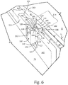
- FIG. 6 is a perspective view of seal retention block 130 and seal assembly, including aft inner diameter seal support structure 70, and seal 80. Although described with respect to seal 80, it should be understood that the disclosed embodiment of retention block 130 applies equally to seals 76, 78, and 82. Similar to seal 76, seal 80 can be a split-ring seal having first end 110 and second end 112, each having reduced thickness (t s ), overlapping, and forming end gap 114.
- FIG. 7 is a schematic top view of retention block 130 and seal assembly.
- Retention block 130 can be an H-shaped structure.
- Retention block 130 can have first portion 132 with inner surface 133, second portion 134 with inner surface 135, stem 136, first face 138, and second face 140.
- Stem 136 can connect first portion 132 and second portion 134 to form the H-shape.
- First face 138 can be located at one end of retention block 130 and can include an end section of each of first portion 132, second portion 134, and stem 136.
- Second face 140 can be located at an end of retention block 130 opposite to first face 138.
- Second face 140 can include an opposite end section of each of first portion 132, second portion 134, and stem 136.
- Inner surface 133 of first portion 132 and inner surface 135 of second portion 134 can adjoin first face 138 at the one end and second face 140 at the opposite end.
- Stem 136 can have first outer surface 142 and second outer surface 144.
- First and second outer surfaces 142 and 144 can each adjoin first face 138 at the one end and second face 140 at the opposite end.
- First and second portions 132 and 134 can be substantially equal in shape and size.
- a resulting symmetrically designed retention block 130 can provide for mistake-proof assembly.
- Inner surfaces 133 and 135 of first and second portions 132 and 134, respectively, and first surface 142 and second surface 144 of stem 136 can each adjoin second face 140 with chamfer 145. Inner surfaces 133 and 135 and first and second surfaces 144 and 136 can also adjoin first face 138 with chamfer 146. Having chamfers 145 and 146 at either face of retention block 130 allows for mistake-proof assembly.
- Aft inner diameter support structure 70 can have groove 148, bordered by flange 147 on one side and surface 149 on the opposite side, for holding seal 80.
- Flange 147 can have an elevated portion with first side 150 and second side 152, opposite first side 150.
- Flange 147 can have slot 154 for retaining retention block 130. Slot 154 can be disposed in the radial direction, opening at a top portion of flange 147 and extending inward, and can extend generally transverse to groove 148.
- Stem 136 of retention block 130 can be press fit into slot 154, with retention block 130 first portion 132 positioned adjacent flange 147 first side 150 and with retention block 130 second portion 134 positioned adjacent flange 147 second side 152.
- a length (l s ) of stem 136, extending from first portion 132 to second portion 134, can be substantially equal to a thickness (t f ) of flange 147 (extending from first side 150 to second side 152), such that first and second portions 134 and 136 contact first and second sides 150 and 152, respectively.
- tack weld 155 can be applied where first and second inner surfaces 133 and 135 of first and second portions 132 and 134, and first and second outer surfaces 142 and 144 of stem 136 adjoin first face 138 (illustrated in FIG. 7 ). Additional tack weld 156 can also be applied where inner surfaces 133 and 135 adjoin first and second sides 150 and 152 of flange 147. It will be understood by one skilled in the art that the placement of tack welds is not limited to the embodiments shown and that a tack weld can generally be used anywhere along the periphery retention block 130 where retention block 130 meets flange 147 or support structure 70.
- the elevated portion of flange 147 can have cutout 157 where flange is reduced in thickness from first side 150. Reducing the thickness of flange 147 can remove weight from support structure 70 and reduce a size of retention block 130.
- the length (l s ) of stem 136 can be reduced to substantially match a thickness (t f ) of flange 147 along a section of first side 150 where flange 147 has been reduced in thickness (at cutout 157).
- Cutout 157 can have fillet 158 connecting a surface of cutout 157 with first side 150.
- Retention block 130 can have mating chamfer 145 to allow good fit between retention block 130 and flange 147.
- Second portion 134 of retention block 130 can extend into groove 146 to engage seal 80 in end gap 114.
- Second portion 134 can extend into groove 148 a distance that is less than thickness t s of seal 80 at first end 110, such that outer surface 164 of second portion 134 does not contact second end 112 along inner circumferentially extending surface 117 and cause binding upon thermal expansion of seal 80.
- the distance to which second portion 134 extends into end gap 114 can be limited to a distance at which engagement surfaces 166 and 168, located adjacent outer surface 164, are capable of blocking circumferential rotation of seal 80.
- the distance can be greater than 50% and less than 90% percent of a thickness of seal 80, and can commonly be within the range of approximately 60% to 75% of the thickness of seal 80.
- Outer surface 164 and engagement surfaces 166 and 168 can each be rectangular in shape. The rectangular shape can spread out load and reduce contact stress with seal 80.
- seal retention block 130 can be easily removed and replaced if damaged. Seal retention block 130 can remain installed when seal 80 is replaced and can be installed before or after seal 80. Support structures without seal retention features can be retrofitted to accommodate seal retention block 130 by cutting slot 154 into a flange of the existing support structure. The ability to retrofit existing structures eliminates the need for redesign of the support structure or seal in a manner necessary to achieve the same result.
- FIG. 2 illustrates assembly of retention block 130 on inner diameter aft support structure 70 of mid-turbine frame 57, retention block 130 may be suited for use in a variety of seal assemblies, not limited to the application of gas turbine engines.
- retention block 130 may be suited for assembly in other engine sections, including but not limited to, fan, compressor, diffuser, combustor, turbine, and exhaust case seal assemblies.
- retention block 130 is designed for assembly in multiple support structures, including support structure 68, which can be easily adapted to receive retention block 130.
- retention block 90 may require modification to be assembled in support structure 70 due to angled outer surface 172 on support structure 70 (shown in FIG. 2 ). It would be understood by one skilled in the art to modify retention block 90 to adequately mate with or engage an angled support surface.
- a method of limiting circumferential rotation of a split-ring seal for use in a gas turbine engine includes inserting a retention block through a slot in a flange of a support structure and into a groove configured to hold a split-ring seal, and engaging an end of a split-ring seal in the groove with a surface of the retention block.
- the method of the preceding paragraph can optionally include, additionally and/or alternatively, any one or more of the following features:
- a further embodiment of the foregoing method can include providing axial retention of the retention block by (a) engaging first and second sides of the flange with first and second inner sides of the retention block, and/or (b) extending a boss through a portion of the support structure disposed adjacent to the flange and swaging an end of the boss to engage the support structure.
- An anti-rotation device for limiting circumferential movement of a split-ring piston seal in a gas turbine engine includes an H-shaped retention block and a support structure configured to receive the split-ring piston seal and to retain the H-shaped retention block.
- the device of the preceding paragraph can optionally include, additionally and/or alternatively, any one or more of the following features:
- the H-shaped retention block can include a first portion, a second portion, a stem connecting the first portion and the second portion, and a first face at one end of the H-shaped retention block and a second face at an opposite end of the H-shaped retention block.
- the first face can include an end section of each of the first portion, the second portion, and the stem.
- the second face can include an opposite end section of each of the first portion, the second portion, and the stem.
- first and second portions can each comprise inner surfaces separated from one another by the stem and adjoining the first face at the one end and the second face at the opposite end, and wherein the stem can comprises opposite first and second outer surfaces each adjoining the first face at the one end and the second face at the opposite end.
- the inner surfaces of the first and second portions and the first and second outer surfaces of the stem can join at least one of the first and second faces with a chamfer.
- the support structure can include a flange and a slot extending through the flange for receiving the stem of the retention block.
- the flange can have first side and a second side opposite the first side.
- a section of the first side of the flange can be reduced in thickness and an inner surface of the first portion of the retention block can engage the first side of the flange along the section of the first side where the flange is reduced in thickness.
- the stem can include first and second outer surfaces each adjoining the first face at the one end and the second face at the opposite end.
- a length of the stem, extending from the first portion to the second portion, can be substantially equal to a thickness of the flange along the section of the first side where the flange is reduced in thickness.
- the support structure can include a groove adjacent the flange, and wherein the split-ring seal can be disposed at least partially in the groove.
- the split-ring seal can have first and second ends that overlap and create an end gap.
- the second portion of the retention block can extend into the groove of the support structure to engage the seal in the end gap.
- first and second ends of the split-ring seal can each have a thickness that is less than a thickness along the length of the seal, and wherein the second portion of the retention block can extend into the groove a distance that is less than the thickness of the first end.
- An anti-rotation device for limiting circumferential movement of a split-ring piston seal includes a retention block with a first side, a first face adjacent to the first side, a stem extending outward from the first side, and a boss extending outward from the first face.
- the device of the preceding paragraph can optionally include, additionally and/or alternatively, any one or more of the following features:
- the stem can have a height equal to a height of the retention block, extending from the first face to a second face opposite the first face, and a width that is less than a width of the retention block.
- the stem can be substantially centered along the first side of the retention block.
- a further embodiment of the device of the foregoing paragraphs can include a flange and a slot extending through the flange for receiving the stem of the retention block.
- a further embodiment of the device of the foregoing paragraphs can include a groove adjacent the flange.
- the split-ring seal can be disposed in the groove and can have first and second ends of reduced thickness. The first and second ends can overlap and create an end gap between the first end and a portion of the second end where the seal increases in thickness.
- the stem of the retention block can extend through the slot of the flange and into the groove of the support structure to engage the seal in the end gap.
- stem of the retention block can extend into the groove a distance that is less than the thickness of the first end.
- the support structure can include a hole for receiving the boss of the retention block.
- first face of the retention block can sit on a first surface of the support structure and the boss can extend through a full thickness of the support structure such that an end of the boss can protrude from a second surface of the support structure.
- the end of the boss can be swaged to engage the second surface of the support structure.
- any relative terms or terms of degree used herein such as “substantially”, “essentially”, “generally”, “approximately” and the like, should be interpreted in accordance with and subject to any applicable definitions or limits expressly stated herein. In all instances, any relative terms or terms of degree used herein should be interpreted to broadly encompass any relevant disclosed embodiments as well as such ranges or variations as would be understood by a person of ordinary skill in the art in view of the entirety of the present disclosure, such as to encompass ordinary manufacturing tolerance variations, incidental alignment variations, alignment or shape variations induced by thermal, rotational or vibrational operational conditions, and the like.
Landscapes
- Engineering & Computer Science (AREA)
- General Engineering & Computer Science (AREA)
- Mechanical Engineering (AREA)
- Chemical & Material Sciences (AREA)
- Combustion & Propulsion (AREA)
- Turbine Rotor Nozzle Sealing (AREA)
- Gasket Seals (AREA)
Abstract
Description
- The present application relates generally to seal assemblies, and more particularly to split-ring piston seals.
- Piston seals (or piston rings) can be used in a variety of applications to create a seal between fluids of different pressures and temperatures. Piston seals can exhibit significant wear (e.g., fretting can cause narrowing of seals, as well as shortening of split-ring seals) when allowed to rotate freely in a circumferential direction. Wear is not limited to applications involving the sealing of rotating components. Piston seals applied between static, non-rotating, structures, may also exhibit wear due to rotation.
- In one aspect of the present invention, a method of limiting circumferential rotation of a split-ring seal for use in a gas turbine engine includes inserting a retention block through a slot in a flange of a support structure and into a groove configured to hold a split-ring seal, and engaging an end of a split-ring seal in the groove with a surface of the retention block.
- In another aspect of the present invention, an anti-rotation device for limiting circumferential movement of a split-ring piston seal in a gas turbine engine includes an H-shaped retention block and a support structure configured to receive the split-ring piston seal and to retain the H-shaped retention block.
- In yet another aspect of the present invention, an anti-rotation device for limiting circumferential movement of a split-ring piston seal includes a retention block. The retention block includes a first side, a first face adjacent to the first side, a stem extending outward from the first side, and a boss extending outward from the first face.
- The present summary is provided only by way of example, and not limitation. Other aspects of the present disclosure will be appreciated in view of the entirety of the present disclosure, including the entire text, claims and accompanying figures.
-
-
FIG. 1 is a quarter-sectional view of a gas turbine engine. -
FIG. 2 is a cross-sectional view of a mid-turbine frame of the gas turbine engine. -
FIG. 3 is a perspective view of one embodiment of an anti-rotation seal retention block. -
FIG. 4 is a cross-sectional view of the anti-rotation seal retention block, taken along the 4-4 line ofFIG. 3 . -
FIG. 5 is a cross-sectional view of the anti-rotation seal retention block, taken along the 5-5 line ofFIG. 3 . -
FIG. 6 is a perspective view of another embodiment of an anti-rotation seal retention block. -
FIG. 7 is a schematic top view of the anti-rotation seal retention block ofFIG. 6 . - While the above-identified figures set forth embodiments of the present invention, other embodiments are also contemplated, as noted in the discussion. In all cases, this disclosure presents the invention by way of representation and not limitation. It should be understood that numerous other modifications and embodiments can be devised by those skilled in the art, which fall within the scope and spirit of the principles of the invention. The figures may not be drawn to scale, and applications and embodiments of the present invention may include features, steps and/or components not specifically shown in the drawings.
-
FIG. 1 is a quarter-sectional view of agas turbine engine 20 that includesfan section 22,compressor section 24,combustor section 26 andturbine section 28. Alternative engines might include an augmenter section (not shown) among other systems or features.Fan section 22 drives air along bypass flow path B whilecompressor section 24 draws air in along core flow path C where air is compressed and communicated tocombustor section 26. Incombustor section 26, air is mixed with fuel and ignited to generate a high pressure exhaust gas stream that expands throughturbine section 28 where energy is extracted and utilized to drivefan section 22 andcompressor section 24. - Although the disclosed non-limiting embodiment depicts a turbofan gas turbine engine, it should be understood that the concepts described herein are not limited to use with turbofans as the teachings may be applied to other types of turbine engines; for example a turbine engine including a three-spool architecture in which three spools concentrically rotate about a common axis and where a low spool enables a low pressure turbine to drive a fan via a gearbox, an intermediate spool that enables an intermediate pressure turbine to drive a first compressor of the compressor section, and a high spool that enables a high pressure turbine to drive a high pressure compressor of the compressor section.
- The
example engine 20 generally includeslow speed spool 30 andhigh speed spool 32 mounted for rotation about an engine central longitudinal axis A relative to an enginestatic structure 36 viaseveral bearing systems 38. It should be understood thatvarious bearing systems 38 at various locations may alternatively or additionally be provided. -
Low speed spool 30 generally includesinner shaft 40 that connectsfan 42 and low pressure (or first)compressor section 44 to low pressure (or first)turbine section 46.Inner shaft 40 drivesfan 42 through a speed change device, such as gearedarchitecture 48, to drivefan 42 at a lower speed thanlow speed spool 30. High-speed spool 32 includesouter shaft 50 that interconnects high pressure (or second)compressor section 52 and high pressure (or second)turbine section 54.Inner shaft 40 andouter shaft 50 are concentric and rotate viabearing systems 38 about engine central longitudinal axis A. - Combustor 56 is arranged between
high pressure compressor 52 andhigh pressure turbine 54. In one example,high pressure turbine 54 includes at least two stages to provide a double stagehigh pressure turbine 54. In another example,high pressure turbine 54 includes only a single stage. As used herein, a "high pressure" compressor or turbine experiences a higher pressure than a corresponding "low pressure" compressor or turbine. - The example
low pressure turbine 46 has a pressure ratio that is greater than about 5. The pressure ratio of the examplelow pressure turbine 46 is measured prior to an inlet oflow pressure turbine 46 as related to the pressure measured at the outlet oflow pressure turbine 46 prior to an exhaust nozzle. -
Mid-turbine frame 57 of enginestatic structure 36 is arranged generally betweenhigh pressure turbine 54 andlow pressure turbine 46.Mid-turbine frame 57 further supports bearingsystems 38 inturbine section 28 as well as setting airflow enteringlow pressure turbine 46. - The core airflow C is compressed by
low pressure compressor 44 then byhigh pressure compressor 52 mixed with fuel and ignited incombustor 56 to produce high speed exhaust gases that are then expanded throughhigh pressure turbine 54 andlow pressure turbine 46.Mid-turbine frame 57 includes airfoils/vanes 59, which are in the core airflow path and function as an inlet guide vane forlow pressure turbine 46. Utilizingvanes 59 ofmid-turbine frame 57 as inlet guide vanes forlow pressure turbine 46 decreases the length oflow pressure turbine 46 without increasing the axial length ofmid-turbine frame 57. Reducing or eliminating the number of vanes inlow pressure turbine 46 shortens the axial length ofturbine section 28. Thus, the compactness ofgas turbine engine 20 is increased and a higher power density may be achieved. - The disclosed
gas turbine engine 20 in one example is a high-bypass geared aircraft engine. In a further example,gas turbine engine 20 includes a bypass ratio greater than about six (6), with an example embodiment being greater than about ten (10). The example gearedarchitecture 48 is an epicyclical gear train, such as a planetary gear system, star gear system or other known gear system, with a gear reduction ratio of greater than about 2.3. - In one disclosed embodiment,
gas turbine engine 20 includes a bypass ratio greater than about ten (10:1) and the fan diameter is significantly larger than an outer diameter oflow pressure compressor 44. It should be understood, however, that the above parameters are only exemplary of one embodiment of a gas turbine engine including a geared architecture and that the present disclosure is applicable to other gas turbine engines. -
FIG. 2 is a cross-sectional view ofmid-turbine frame 57, which includes airfoils/vanes 59 (each having leadingedge 60 and trailing edge 62),outer platform 64,inner platform 66, inner diameter forwardseal support structure 68, inner diameter aftseal support structure 70, forwardinner diameter seal 76 andouter diameter seal 78, aftinner diameter seal 80 andouter diameter seal 82.Seals seals spring 78 can be biased inward towardouter platform 64. As shown inFIG. 2 , forwardinner seal 76 and aftinner seal 80 can be axially retained insupport structures inner platform 66, respectively. (Seals FIG. 2 ). All seals (76, 78, 80, and 82) may exhibit substantial wear, including reduced thickness and length due to fretting, if allowed to freely rotate in a circumferential direction. -
FIGS. 3-5 show one embodiment of an anti-rotation seal retention feature and seal assembly used to limit circumferential movement of forwardinner diameter seal 76.FIG. 3 is a perspective view ofseal retention block 90.FIG. 4 is a cross-sectional view ofseal retention block 90 taken along the 4-4 line ofFIG. 3 .FIG. 5 is a cross-sectional view ofseal retention block 90 taken along the 5-5 line ofFIG. 3 . Although described with respect to forwardinner diameter seal 76, it should be understood that the disclosed embodiment ofretention block 90 applies equally toseals -
Seal retention block 90 can includefirst side 92,second side 94 located oppositefirst side 92, stem 96 extending outward fromfirst side 92,first face 98, andsecond face 100, located oppositefirst face 98. First and second faces 98 and 100 can be inner and outer surfaces, respectively, each being located adjacent first andsecond sides retention block 90.Stem 96 can have a height (hs) equal to a height (hb) ofretention bock 90, extending fromfirst face 98 tosecond face 100.Stem 96 can have a width (ws) less than a width (wb) ofseal retention block 90 and can be substantially centered alongfirst side 92. -
Support structure 68 can includeflange 102, which can make up one of twowalls groove 108. Groove 108 can be configured to hold forwardinner seal 76.Seal 76 can be a split ring seal havingfirst end 110 andsecond end 112.First end 110 andsecond end 112 can each be reduced in thickness (ts), such that eachend groove 108, extending fromwall 104 towall 106. While in the illustrated embodiment first and second ends 110 and 112 have equal thickness ts, first and second ends 110 and 112 can have different thicknesses. The reduced thickness (ts) can allow ends 110 and 112 to form a shiplap overlap withingroove 108. First and second ends 110 and 112 can each be reduced in length to formend gap 114, which can extend fromend surface 113 offirst end 110 to a portion ofsecond end 112 whereseal 76 increases in thickness, and fromend surface 115 ofsecond end 112 to a portion offirst end 110 whereseal 76 increases in thickness.End gap 114 can allowseal 76 to expand due to thermal changes during operation without buckling. -
Flange 102 can haveslot 116, which can be aligned withend gap 114. Slot 116 can extend in a radial direction, opening at a top portion offlange 102 and extending inward.Stem 96 can extend throughslot 116 and at least partially intoend gap 114 to block circumferential rotation ofseal 76 during operation. As shown inFIGS. 3 and4 , stem 96 can extend into end gap 114 (and groove 108, betweenwalls 104 and 106) a distance less than the thickness ts offirst end 110, such thatstem 96 does not contactsecond end 112 along inner circumferentially extendingsurface 117 and cause binding upon thermal expansion ofseal 76. Generally, the distance can be greater than 50% and less than 90% percent of the thickness ts, and can commonly be within the range of approximately 60% to 75% of the thickness ts. The distance to which stem 96 extends intoend gap 114 can be limited to a distance at which stem 96 is capable of blocking circumferential rotation ofseal 76 by contacting end surfaces of one or both first and second ends 110 and 112. -
Stem 96 can be press fit intoslot 116 inflange 102 and can be positioned such thatfirst face 98 contacts a firstouter surface 118 of support structure 68 (illustrated inFIGS. 4 and 5 ). Firstouter surface 118 ofsupport structure 68 can be oriented substantially perpendicularly toflange 102. A tack weld can be applied anywhere along the periphery ofseal retention block 90 whereseal retention block 90 interfaces withsupport structure 68 orflange 102. As shown inFIG. 3 , tackweld 119 is applied along a portion of a perimeter ofretention block 90 where first face 98 contacts firstouter surface 118. Additionally, sealretention block 90 can includeboss 120 extending outward from first face 98 (FIGS. 4 and 5 ).Boss 120 can provide axial and radial retention ofseal retention block 90.Boss 120 can be semi-tubular. Alternatively,boss 120 can be a rivet, screw, bolt, or other suitable fastener. As shown inFIGS. 4 and 5 ,boss 120 can extend throughhole 122 insupport structure 68, such thatend 124 ofboss 120 protrudes through a full thickness ofsupport structure 68 and protrudes fromsecond surface 126 ofsupport structure 68. As shown inFIG. 5 , end 124 can be swaged to engagesecond surface 126, providing radial retention ofseal retention block 90. The combination ofpress fitting stem 96 andswaging boss 120 into mating components ofsupport structure 68, as well as applyingtack weld 119, keeps seal retention block in position without the need of additional fasteners, which could add weight. -
Seal retention block 90 can be easily removed and replaced if damaged.Seal retention block 90 can remain installed whenseal 76 is replaced and can be installed before or afterseal 76. Support structures without seal retention features may be retrofitted to accommodateseal retention block 90 by cutting a slot into a flange and hole into an adjacent support structure. The ability to retrofit existing structures eliminates the need for redesign of the support structure or seal in a manner necessary to achieve the same result. AlthoughFIG. 2 illustrates assembly ofretention block 90 on inner diameterforward support structure 68 ofmid-turbine frame 57,retention block 90 may be suited for use in a variety of seal assemblies, not limited to the application of gas turbine engines. Within gas turbine engines,retention block 90 may be suited for assembly in other engine sections, including but not limited to, fan, compressor, diffuser, combustor, turbine, and exhaust case seal assemblies. -
FIGS. 6 and7 illustrate another embodiment of an anti-rotation seal retention feature.FIG. 6 is a perspective view ofseal retention block 130 and seal assembly, including aft inner diameterseal support structure 70, andseal 80. Although described with respect to seal 80, it should be understood that the disclosed embodiment ofretention block 130 applies equally toseals seal 80 can be a split-ring seal havingfirst end 110 andsecond end 112, each having reduced thickness (ts), overlapping, and formingend gap 114.FIG. 7 is a schematic top view ofretention block 130 and seal assembly. -
Retention block 130 can be an H-shaped structure.Retention block 130 can havefirst portion 132 withinner surface 133,second portion 134 withinner surface 135,stem 136,first face 138, andsecond face 140.Stem 136 can connectfirst portion 132 andsecond portion 134 to form the H-shape.First face 138 can be located at one end ofretention block 130 and can include an end section of each offirst portion 132,second portion 134, andstem 136.Second face 140 can be located at an end ofretention block 130 opposite tofirst face 138.Second face 140 can include an opposite end section of each offirst portion 132,second portion 134, andstem 136.Inner surface 133 offirst portion 132 andinner surface 135 ofsecond portion 134 can adjoinfirst face 138 at the one end andsecond face 140 at the opposite end.Stem 136 can have firstouter surface 142 and secondouter surface 144. First and secondouter surfaces first face 138 at the one end andsecond face 140 at the opposite end. First andsecond portions retention block 130 can provide for mistake-proof assembly. -
Inner surfaces second portions first surface 142 andsecond surface 144 ofstem 136 can each adjoinsecond face 140 withchamfer 145.Inner surfaces second surfaces first face 138 withchamfer 146. Havingchamfers retention block 130 allows for mistake-proof assembly. - Aft inner
diameter support structure 70 can havegroove 148, bordered byflange 147 on one side andsurface 149 on the opposite side, for holdingseal 80.Flange 147 can have an elevated portion withfirst side 150 andsecond side 152, oppositefirst side 150. Although the disclosed embodiment illustrates a continuous flange with a local elevated portion, it will be understood by one skilled in the art that support structures can have local flanges or a continuous flange with constant height.Flange 147 can haveslot 154 for retainingretention block 130. Slot 154 can be disposed in the radial direction, opening at a top portion offlange 147 and extending inward, and can extend generally transverse to groove 148.Stem 136 ofretention block 130 can be press fit intoslot 154, withretention block 130first portion 132 positionedadjacent flange 147first side 150 and withretention block 130second portion 134 positionedadjacent flange 147second side 152. A length (ls) ofstem 136, extending fromfirst portion 132 tosecond portion 134, can be substantially equal to a thickness (tf) of flange 147 (extending fromfirst side 150 to second side 152), such that first andsecond portions second sides tack weld 155 can be applied where first and secondinner surfaces second portions outer surfaces stem 136 adjoin first face 138 (illustrated inFIG. 7 ).Additional tack weld 156 can also be applied whereinner surfaces second sides flange 147. It will be understood by one skilled in the art that the placement of tack welds is not limited to the embodiments shown and that a tack weld can generally be used anywhere along theperiphery retention block 130 whereretention block 130 meetsflange 147 orsupport structure 70. - As shown in
FIGS. 6 and7 , the elevated portion offlange 147 can havecutout 157 where flange is reduced in thickness fromfirst side 150. Reducing the thickness offlange 147 can remove weight fromsupport structure 70 and reduce a size ofretention block 130. The length (ls) ofstem 136 can be reduced to substantially match a thickness (tf) offlange 147 along a section offirst side 150 whereflange 147 has been reduced in thickness (at cutout 157).Cutout 157 can havefillet 158 connecting a surface ofcutout 157 withfirst side 150.Retention block 130 can havemating chamfer 145 to allow good fit betweenretention block 130 andflange 147. -
Second portion 134 ofretention block 130 can extend intogroove 146 to engageseal 80 inend gap 114.Second portion 134 can extend into groove 148 a distance that is less than thickness ts ofseal 80 atfirst end 110, such thatouter surface 164 ofsecond portion 134 does not contactsecond end 112 along inner circumferentially extendingsurface 117 and cause binding upon thermal expansion ofseal 80. Similar to the previous embodiment, the distance to whichsecond portion 134 extends intoend gap 114 can be limited to a distance at which engagement surfaces 166 and 168, located adjacentouter surface 164, are capable of blocking circumferential rotation ofseal 80. Generally, the distance can be greater than 50% and less than 90% percent of a thickness ofseal 80, and can commonly be within the range of approximately 60% to 75% of the thickness ofseal 80.Outer surface 164 andengagement surfaces seal 80. - Similar to the previous embodiment,
seal retention block 130 can be easily removed and replaced if damaged.Seal retention block 130 can remain installed whenseal 80 is replaced and can be installed before or afterseal 80. Support structures without seal retention features can be retrofitted to accommodateseal retention block 130 by cuttingslot 154 into a flange of the existing support structure. The ability to retrofit existing structures eliminates the need for redesign of the support structure or seal in a manner necessary to achieve the same result. Although,FIG. 2 illustrates assembly ofretention block 130 on inner diameter aftsupport structure 70 ofmid-turbine frame 57,retention block 130 may be suited for use in a variety of seal assemblies, not limited to the application of gas turbine engines. Within gas turbine engines,retention block 130 may be suited for assembly in other engine sections, including but not limited to, fan, compressor, diffuser, combustor, turbine, and exhaust case seal assemblies. In the disclosed engine,retention block 130 is designed for assembly in multiple support structures, includingsupport structure 68, which can be easily adapted to receiveretention block 130. Unlikeretention block 130,retention block 90 may require modification to be assembled insupport structure 70 due to angledouter surface 172 on support structure 70 (shown inFIG. 2 ). It would be understood by one skilled in the art to modifyretention block 90 to adequately mate with or engage an angled support surface. - The following are non-exclusive descriptions of possible embodiments of the present invention.
- A method of limiting circumferential rotation of a split-ring seal for use in a gas turbine engine according to an exemplary embodiment of this disclosure, among other possible things includes inserting a retention block through a slot in a flange of a support structure and into a groove configured to hold a split-ring seal, and engaging an end of a split-ring seal in the groove with a surface of the retention block.
- The method of the preceding paragraph can optionally include, additionally and/or alternatively, any one or more of the following features:
- A further embodiment of the foregoing method can include providing axial retention of the retention block by (a) engaging first and second sides of the flange with first and second inner sides of the retention block, and/or (b) extending a boss through a portion of the support structure disposed adjacent to the flange and swaging an end of the boss to engage the support structure.
- An anti-rotation device for limiting circumferential movement of a split-ring piston seal in a gas turbine engine according to an exemplary embodiment of this disclosure includes an H-shaped retention block and a support structure configured to receive the split-ring piston seal and to retain the H-shaped retention block.
- The device of the preceding paragraph can optionally include, additionally and/or alternatively, any one or more of the following features:
- A further embodiment of the device of the foregoing paragraph, wherein the H-shaped retention block can include a first portion, a second portion, a stem connecting the first portion and the second portion, and a first face at one end of the H-shaped retention block and a second face at an opposite end of the H-shaped retention block. The first face can include an end section of each of the first portion, the second portion, and the stem. The second face can include an opposite end section of each of the first portion, the second portion, and the stem.
- A further embodiment of the device of the foregoing paragraphs, wherein the first and second portions can each comprise inner surfaces separated from one another by the stem and adjoining the first face at the one end and the second face at the opposite end, and wherein the stem can comprises opposite first and second outer surfaces each adjoining the first face at the one end and the second face at the opposite end. The inner surfaces of the first and second portions and the first and second outer surfaces of the stem can join at least one of the first and second faces with a chamfer.
- A further embodiment of the device of the foregoing paragraphs, wherein the support structure can include a flange and a slot extending through the flange for receiving the stem of the retention block.
- A further embodiment of the device of the foregoing paragraphs, wherein the flange can have first side and a second side opposite the first side. A section of the first side of the flange can be reduced in thickness and an inner surface of the first portion of the retention block can engage the first side of the flange along the section of the first side where the flange is reduced in thickness.
- A further embodiment of the device of the foregoing paragraphs, wherein the stem can include first and second outer surfaces each adjoining the first face at the one end and the second face at the opposite end. A length of the stem, extending from the first portion to the second portion, can be substantially equal to a thickness of the flange along the section of the first side where the flange is reduced in thickness.
- A further embodiment of the device of the foregoing paragraphs, wherein the stem of the retention block can be press fit into the slot of the flange.
- A further embodiment of the device of the foregoing paragraphs, wherein the support structure can include a groove adjacent the flange, and wherein the split-ring seal can be disposed at least partially in the groove. The split-ring seal can have first and second ends that overlap and create an end gap. The second portion of the retention block can extend into the groove of the support structure to engage the seal in the end gap.
- A further embodiment of the device of the foregoing paragraphs, wherein the first and second ends of the split-ring seal can each have a thickness that is less than a thickness along the length of the seal, and wherein the second portion of the retention block can extend into the groove a distance that is less than the thickness of the first end.
- An anti-rotation device for limiting circumferential movement of a split-ring piston seal according to an exemplary embodiment of the present disclosure includes a retention block with a first side, a first face adjacent to the first side, a stem extending outward from the first side, and a boss extending outward from the first face.
- The device of the preceding paragraph can optionally include, additionally and/or alternatively, any one or more of the following features:
- A further embodiment of the device of the foregoing paragraphs, wherein the stem can have a height equal to a height of the retention block, extending from the first face to a second face opposite the first face, and a width that is less than a width of the retention block. The stem can be substantially centered along the first side of the retention block.
- A further embodiment of the device of the foregoing paragraphs can include a flange and a slot extending through the flange for receiving the stem of the retention block.
- A further embodiment of the device of the foregoing paragraphs, wherein the stem of the retention block can be press fit into the slot of the flange.
- A further embodiment of the device of the foregoing paragraphs can include a groove adjacent the flange. The split-ring seal can be disposed in the groove and can have first and second ends of reduced thickness. The first and second ends can overlap and create an end gap between the first end and a portion of the second end where the seal increases in thickness. The stem of the retention block can extend through the slot of the flange and into the groove of the support structure to engage the seal in the end gap.
- A further embodiment of the device of the foregoing paragraphs, wherein the stem of the retention block can extend into the groove a distance that is less than the thickness of the first end.
- A further embodiment of the device of the foregoing paragraphs, wherein the support structure can include a hole for receiving the boss of the retention block.
- A further embodiment of the device of the foregoing paragraphs, wherein the boss can be disposed at a right angle with respect to the stem.
- A further embodiment of the device of the foregoing paragraphs, wherein the first face of the retention block can sit on a first surface of the support structure and the boss can extend through a full thickness of the support structure such that an end of the boss can protrude from a second surface of the support structure. The end of the boss can be swaged to engage the second surface of the support structure.
- Any relative terms or terms of degree used herein, such as "substantially", "essentially", "generally", "approximately" and the like, should be interpreted in accordance with and subject to any applicable definitions or limits expressly stated herein. In all instances, any relative terms or terms of degree used herein should be interpreted to broadly encompass any relevant disclosed embodiments as well as such ranges or variations as would be understood by a person of ordinary skill in the art in view of the entirety of the present disclosure, such as to encompass ordinary manufacturing tolerance variations, incidental alignment variations, alignment or shape variations induced by thermal, rotational or vibrational operational conditions, and the like.
- While the invention has been described with reference to an exemplary embodiment(s), it will be understood by those skilled in the art that various changes may be made and equivalents may be substituted for elements thereof without departing from the scope of the invention. In addition, many modifications may be made to adapt a particular situation or material to the teachings of the invention without departing from the essential scope thereof. Therefore, it is intended that the invention not be limited to the particular embodiment(s) disclosed, but that the invention will include all embodiments falling within the scope of the appended claims.
Claims (15)
- A method of limiting circumferential rotation of a split-ring seal (76, 78, 80, 82) for use in a gas turbine engine (20), the method comprising:inserting a retention block (90; 130) through a slot (116; 154) in a flange (102; 147) of a support structure (68; 70) and into a groove (108; 148) configured to hold a split-ring seal (76, 78, 80, 82); andengaging an end (110) of a split-ring seal (76, 78, 80, 82) in the groove (108; 148) with a surface of the retention block (90; 130).
- The method of claim 1, further comprising:providing axial retention of the retention block (90; 130) using a method selected from the group consisting of: engaging first and second sides (150, 152) of the flange (102; 147) with first and second inner sides (92; 94) of the retention block (90; 130); and extending a boss (120) through a portion (122) of the support structure (68; 70) disposed adjacent to the flange (102; 147) and swaging an end (124) of the boss (120) to engage the support structure (68; 70).
- An anti-rotation device for limiting circumferential movement of a split-ring piston seal (76, 78, 80, 82) in a gas turbine engine (20), the device comprising:a retention block (90; 130); anda support structure (68;70) configured to receive the split-ring piston seal (76, 78, 80, 82) and to retain the retention block (90; 130).
- The anti-rotation device of claim 3, wherein the retention block (130) is H-shaped and comprises:a first portion (132);a second portion (134);a stem (136) connecting the first portion (132) and the second portion (134);a first face (138) at one end of the H-shaped retention block (130), the first face (138) comprising an end section of each of the first portion (132), the second portion (134), and the stem (136); anda second face (140) at an opposite end of the H-shaped retention block (130), the second face (140) comprising an opposite end section of each of the first portion (132), the second portion (134), and the stem (136).
- The device of claim 4, wherein the first (132) and second (134) portions each comprise inner surfaces (133, 135) separated from one another by the stem (136) and adjoining the first face (138) at the one end and the second face (140) at the opposite end, and wherein the stem (136) comprises opposite first (142) and second (144) outer surfaces each adjoining the first face (138) at the one end and the second face (140) at the opposite end, the inner surfaces (133, 135) of the first and second portions (132, 134) and the first and second outer surfaces (142, 144) of the stem (136) joining at least one of the first and second faces (138, 140) with a chamfer (145, 146).
- The device of claim 4 or 5, wherein the support structure (70) comprises:a flange (147); anda slot (154) extending through the flange (147) for receiving the stem (136) of the retention block (90; 130) wherein, optionally, the flange (147) has a first side (150) and a second side (152) opposite the first side (150), wherein a section of the first side (150) of the flange (147) is reduced in thickness and wherein an inner surface (133) of the first portion (132) of the retention block (130) engages the first side (150) of the flange (147) along the section of the first side (150) where the flange (147) is reduced in thickness, wherein, optionally, the stem (136) further comprises first and second outer surfaces (142, 144) each adjoining the first face (138) at the one end and the second face (140) at the opposite end, wherein a length (ls) of the stem (136), extending from the first portion (132) to the second portion (134), is substantially equal to a thickness (tf) of the flange (147) along the section of the first side (150) where the flange (147) is reduced in thickness.
- The device of claim 6, wherein the stem (136) of the retention block (130) is press fit into the slot (154) of the flange (147).
- The device of claim 6 or 7, wherein the support structure (70) further comprises:a groove (148) adjacent the flange (147), and wherein the split-ring seal (80) is disposed at least partially in the groove (148), the split-ring seal (80) having first and second ends (110, 112) that overlap and create an end gap (114), wherein the second portion (134) of the retention block (130) extends into the groove (148) of the support structure (70) to engage the seal (80) in the end gap (114), wherein, optionally, the first and second ends (110, 112) of the split-ring seal (80) each have a thickness (ts) that is less than a thickness along the length of the seal (80), and wherein the second portion (134) of the retention block (130) extends into the groove (148) a distance that is less than the thickness (ts) of the first end (110).
- The anti-rotation device of claim 3, wherein the retention block (90) comprises:a first side (92);a first face (98) adjacent to the first side (92);a stem (96) extending outward from the first side (92); anda boss (120) extending outward from the first face (98).
- The device of claim 9, wherein the stem (96) has a height (hs) equal to a height (hb) of the retention block (90), extending from the first face (98) to a second face (100) opposite the first face (98), and a width that is less than a width of the retention block (90), and wherein the stem (96) is substantially centered along the first side (92) of the retention block (90).
- The device of claim 9 or 10, wherein the support structure (68) comprises:a flange (102); anda slot (116) extending through the flange (102) for receiving the stem (96) of the retention block (90), wherein, optionally, the stem (96) of the retention block (90), is press fit into the slot (116) of the flange (102).
- The device of claim 11, wherein the support structure (68) further comprises:a groove (108) adjacent the flange (102), and wherein the split-ring seal (76) is disposed in the groove (108), the split-ring seal (76) having first and second ends (110, 112) of reduced thickness, wherein the first and second ends (110, 112) overlap and create an end gap (114) between the first end (110) and a portion of the second end (112) where the seal (76) increases in thickness, and wherein the stem (96) of the retention block (90) extends through the slot (116) of the flange (102) and into the groove (108) of the support structure (68) to engage the seal (76) in the end gap (114), wherein, optionally, the stem (96) of the retention block (90) extends into the groove (108) a distance that is less than the thickness of the first end (110).
- The device of any of claims 9 to 12, wherein the support structure (68) further comprises a hole (122) for receiving the boss (120) of the retention block (90).
- The device of any of claims 9 to 13, wherein the boss (120) is disposed at a right angle with respect to the stem (96).
- The device of any of claims 9 to 14, wherein the first face (98) of the retention block (96) sits on a first surface (118) of the support structure (68) and wherein the boss (120) extends through a full thickness of the support structure (68) such that an end (124) of the boss (120) protrudes from a second surface (126) of the support structure (68), and wherein the end (124) of the boss (120) is swaged to engage the second surface (126) of the support structure (68).
Applications Claiming Priority (1)
| Application Number | Priority Date | Filing Date | Title |
|---|---|---|---|
| US15/052,457 US10215043B2 (en) | 2016-02-24 | 2016-02-24 | Method and device for piston seal anti-rotation |
Publications (2)
| Publication Number | Publication Date |
|---|---|
| EP3211277A1 true EP3211277A1 (en) | 2017-08-30 |
| EP3211277B1 EP3211277B1 (en) | 2020-05-06 |
Family
ID=58108556
Family Applications (1)
| Application Number | Title | Priority Date | Filing Date |
|---|---|---|---|
| EP17157485.8A Active EP3211277B1 (en) | 2016-02-24 | 2017-02-22 | Method and device for piston seal anti-rotation |
Country Status (2)
| Country | Link |
|---|---|
| US (2) | US10215043B2 (en) |
| EP (1) | EP3211277B1 (en) |
Cited By (1)
| Publication number | Priority date | Publication date | Assignee | Title |
|---|---|---|---|---|
| EP4446624A1 (en) * | 2023-04-14 | 2024-10-16 | Pratt & Whitney Canada Corp. | Piston ring with integrated anti-rotation feature |
Families Citing this family (4)
| Publication number | Priority date | Publication date | Assignee | Title |
|---|---|---|---|---|
| GB2571802A (en) * | 2018-03-06 | 2019-09-11 | Rolls Royce Plc | A Gas Turbine Engine Combustion Arrangement and a Gas Turbine Engine |
| EP4158178A4 (en) * | 2020-05-27 | 2024-10-30 | Cummins, Inc. | Anti-polish ring for an engine cylinder |
| US12018567B2 (en) * | 2022-05-31 | 2024-06-25 | Pratt & Whitney Canada Corp. | Joint between gas turbine engine components with bonded fastener(s) |
| US20240209942A1 (en) * | 2022-12-23 | 2024-06-27 | Pratt & Whitney Canada Corp. | Seal assembly with anti-rotation feature |
Citations (3)
| Publication number | Priority date | Publication date | Assignee | Title |
|---|---|---|---|---|
| US3768817A (en) * | 1972-04-27 | 1973-10-30 | Westinghouse Electric Corp | Static seal for a gas turbine |
| EP0921272A2 (en) * | 1997-12-03 | 1999-06-09 | Rolls-Royce Plc | Turbine rotor disc assembly |
| US20100066027A1 (en) * | 2008-09-15 | 2010-03-18 | Thurai Manik Vasagar | Intershaft Seal Assembly |
Family Cites Families (35)
| Publication number | Priority date | Publication date | Assignee | Title |
|---|---|---|---|---|
| US890103A (en) * | 1907-08-12 | 1908-06-09 | Michael H Sullivan | Lock for piston-rings. |
| US1332952A (en) * | 1916-04-05 | 1920-03-09 | Rasch Ludvik | Device for closing the slits of packing-rings |
| US2412734A (en) * | 1944-07-19 | 1946-12-17 | Iliffe George | Piston ring |
| US2980088A (en) * | 1959-11-16 | 1961-04-18 | Cooper Bessemer Corp | Internal combustion engine |
| CH525419A (en) * | 1970-12-18 | 1972-07-15 | Bbc Sulzer Turbomaschinen | Sealing device for turbo machines |
| US4184689A (en) | 1978-10-02 | 1980-01-22 | United Technologies Corporation | Seal structure for an axial flow rotary machine |
| GB2063385B (en) * | 1979-11-23 | 1983-06-22 | Cross Mfg Co 1938 Ltd | Gas seals |
| US4540186A (en) | 1985-01-28 | 1985-09-10 | Pneumo Corporation | Anti-rotation device for contracting rod ring seals |
| FR2603947B1 (en) * | 1986-09-17 | 1990-11-30 | Snecma | DEVICE FOR HOLDING A SEAL ON A SHAFT END AND TURBOMACHINE COMPRISING SAME |
| US5318402A (en) | 1992-09-21 | 1994-06-07 | General Electric Company | Compressor liner spacing device |
| US5320487A (en) * | 1993-01-19 | 1994-06-14 | General Electric Company | Spring clip made of a directionally solidified material for use in a gas turbine engine |
| US6457721B1 (en) * | 2001-01-26 | 2002-10-01 | White Consolidated Industries, Inc. | Piston ring locator |
| GB0423923D0 (en) | 2004-10-28 | 2004-12-01 | Rolls Royce Plc | Segmented annular seal for a gas turbine engine |
| US7527469B2 (en) * | 2004-12-10 | 2009-05-05 | Siemens Energy, Inc. | Transition-to-turbine seal apparatus and kit for transition/turbine junction of a gas turbine engine |
| JP4822716B2 (en) * | 2005-02-07 | 2011-11-24 | 三菱重工業株式会社 | Gas turbine with seal structure |
| US20060273524A1 (en) | 2005-06-03 | 2006-12-07 | Weber Leo S | Ring seal with an anti-rotation tab |
| US7581931B2 (en) * | 2006-10-13 | 2009-09-01 | Siemens Energy, Inc. | Gas turbine belly band seal anti-rotation structure |
| GB0703827D0 (en) * | 2007-02-28 | 2007-04-11 | Rolls Royce Plc | Rotor seal segment |
| US20090191050A1 (en) * | 2008-01-24 | 2009-07-30 | Siemens Power Generation, Inc. | Sealing band having bendable tang with anti-rotation in a turbine and associated methods |
| US8453464B2 (en) | 2009-10-01 | 2013-06-04 | Pratt & Whitney Canada Corp. | Air metering device for gas turbine engine |
| GB2477825B (en) | 2010-09-23 | 2015-04-01 | Rolls Royce Plc | Anti fret liner assembly |
| US8905709B2 (en) * | 2010-09-30 | 2014-12-09 | General Electric Company | Low-ductility open channel turbine shroud |
| FR2973829B1 (en) | 2011-04-05 | 2013-05-24 | Snecma | SEALING PLATE FOR AIRCRAFT TURBINE TURBINE TURBINE, COMPRISING |
| US9127557B2 (en) | 2012-06-08 | 2015-09-08 | General Electric Company | Nozzle mounting and sealing assembly for a gas turbine system and method of mounting and sealing |
| US9327368B2 (en) | 2012-09-27 | 2016-05-03 | United Technologies Corporation | Full ring inner air-seal with locking nut |
| US9334738B2 (en) * | 2012-10-23 | 2016-05-10 | Siemens Aktiengesellschaft | Gas turbine including belly band seal anti-rotation device |
| US9347322B2 (en) * | 2012-11-01 | 2016-05-24 | Siemens Aktiengesellschaft | Gas turbine including belly band seal anti-rotation device |
| US9200519B2 (en) * | 2012-11-01 | 2015-12-01 | Siemens Aktiengesellschaft | Belly band seal with underlapping ends |
| US9291065B2 (en) * | 2013-03-08 | 2016-03-22 | Siemens Aktiengesellschaft | Gas turbine including bellyband seal anti-rotation device |
| US9808889B2 (en) * | 2014-01-15 | 2017-11-07 | Siemens Energy, Inc. | Gas turbine including sealing band and anti-rotation device |
| US10024241B2 (en) * | 2013-03-15 | 2018-07-17 | United Technologies Corporation | Turbine engine face seal arrangement including anti-rotation features |
| US9506566B2 (en) | 2013-10-23 | 2016-11-29 | Honeywell International Inc. | Finger-foil seals and gas turbine engines employing the same |
| US9631507B2 (en) * | 2014-07-14 | 2017-04-25 | Siemens Energy, Inc. | Gas turbine sealing band arrangement having a locking pin |
| US9845698B2 (en) * | 2015-06-24 | 2017-12-19 | Siemens Energy, Inc. | Belly band seal with anti-rotation structure |
| US10202863B2 (en) * | 2016-05-23 | 2019-02-12 | United Technologies Corporation | Seal ring for gas turbine engines |
-
2016
- 2016-02-24 US US15/052,457 patent/US10215043B2/en active Active
-
2017
- 2017-02-22 EP EP17157485.8A patent/EP3211277B1/en active Active
-
2019
- 2019-01-11 US US16/245,691 patent/US10865652B2/en active Active
Patent Citations (3)
| Publication number | Priority date | Publication date | Assignee | Title |
|---|---|---|---|---|
| US3768817A (en) * | 1972-04-27 | 1973-10-30 | Westinghouse Electric Corp | Static seal for a gas turbine |
| EP0921272A2 (en) * | 1997-12-03 | 1999-06-09 | Rolls-Royce Plc | Turbine rotor disc assembly |
| US20100066027A1 (en) * | 2008-09-15 | 2010-03-18 | Thurai Manik Vasagar | Intershaft Seal Assembly |
Cited By (1)
| Publication number | Priority date | Publication date | Assignee | Title |
|---|---|---|---|---|
| EP4446624A1 (en) * | 2023-04-14 | 2024-10-16 | Pratt & Whitney Canada Corp. | Piston ring with integrated anti-rotation feature |
Also Published As
| Publication number | Publication date |
|---|---|
| US20190145271A1 (en) | 2019-05-16 |
| EP3211277B1 (en) | 2020-05-06 |
| US20170241281A1 (en) | 2017-08-24 |
| US10215043B2 (en) | 2019-02-26 |
| US10865652B2 (en) | 2020-12-15 |
Similar Documents
| Publication | Publication Date | Title |
|---|---|---|
| US10865652B2 (en) | Method and device for piston seal anti-rotation | |
| US9988923B2 (en) | Seal for gas turbine engine | |
| US10240467B2 (en) | Anti-rotation lug for a gas turbine engine stator assembly | |
| EP3045783A1 (en) | Sliding seal | |
| EP3708772B1 (en) | Tie shaft assembly for a gas turbine engine | |
| US8727935B2 (en) | Fan drive gear system torque frame pin retainer | |
| EP3034807A1 (en) | Gas turbine engine mid-turbine frame tie rod arrangement | |
| EP3181945A1 (en) | Damper seal installation features | |
| US20160169020A1 (en) | Gas turbine engine non-rotating structure wedge seal | |
| EP2971578B1 (en) | Method of assembling a gas turbine engine front architecture and corresponding gas turbine engine front architecture | |
| EP3418492B1 (en) | Bolt retention assembly for gas turbine engine | |
| EP3088662A1 (en) | Multi-stage turbine interstage seal and method of assembly | |
| US10533456B2 (en) | Stator assembly with contoured retention clip for gas turbine engine | |
| US20140090397A1 (en) | Bleed tube attachment | |
| EP3760841B1 (en) | Multi-purpose anti-rotation lock pin | |
| EP4474618A2 (en) | Fan and method of assembling a fan | |
| US20250347368A1 (en) | Non rotating spacer for gas turbine engine | |
| US20190024525A1 (en) | Seal anti-rotation | |
| EP2898189B1 (en) | Multi-stage high pressure compressor case |
Legal Events
| Date | Code | Title | Description |
|---|---|---|---|
| PUAI | Public reference made under article 153(3) epc to a published international application that has entered the european phase |
Free format text: ORIGINAL CODE: 0009012 |
|
| STAA | Information on the status of an ep patent application or granted ep patent |
Free format text: STATUS: THE APPLICATION HAS BEEN PUBLISHED |
|
| AK | Designated contracting states |
Kind code of ref document: A1 Designated state(s): AL AT BE BG CH CY CZ DE DK EE ES FI FR GB GR HR HU IE IS IT LI LT LU LV MC MK MT NL NO PL PT RO RS SE SI SK SM TR |
|
| AX | Request for extension of the european patent |
Extension state: BA ME |
|
| STAA | Information on the status of an ep patent application or granted ep patent |
Free format text: STATUS: REQUEST FOR EXAMINATION WAS MADE |
|
| 17P | Request for examination filed |
Effective date: 20180228 |
|
| RBV | Designated contracting states (corrected) |
Designated state(s): AL AT BE BG CH CY CZ DE DK EE ES FI FR GB GR HR HU IE IS IT LI LT LU LV MC MK MT NL NO PL PT RO RS SE SI SK SM TR |
|
| STAA | Information on the status of an ep patent application or granted ep patent |
Free format text: STATUS: EXAMINATION IS IN PROGRESS |
|
| 17Q | First examination report despatched |
Effective date: 20190104 |
|
| GRAP | Despatch of communication of intention to grant a patent |
Free format text: ORIGINAL CODE: EPIDOSNIGR1 |
|
| STAA | Information on the status of an ep patent application or granted ep patent |
Free format text: STATUS: GRANT OF PATENT IS INTENDED |
|
| INTG | Intention to grant announced |
Effective date: 20191206 |
|
| GRAS | Grant fee paid |
Free format text: ORIGINAL CODE: EPIDOSNIGR3 |
|
| GRAA | (expected) grant |
Free format text: ORIGINAL CODE: 0009210 |
|
| STAA | Information on the status of an ep patent application or granted ep patent |
Free format text: STATUS: THE PATENT HAS BEEN GRANTED |
|
| AK | Designated contracting states |
Kind code of ref document: B1 Designated state(s): AL AT BE BG CH CY CZ DE DK EE ES FI FR GB GR HR HU IE IS IT LI LT LU LV MC MK MT NL NO PL PT RO RS SE SI SK SM TR |
|
| REG | Reference to a national code |
Ref country code: GB Ref legal event code: FG4D |
|
| REG | Reference to a national code |
Ref country code: AT Ref legal event code: REF Ref document number: 1267272 Country of ref document: AT Kind code of ref document: T Effective date: 20200515 Ref country code: CH Ref legal event code: EP |
|
| REG | Reference to a national code |
Ref country code: IE Ref legal event code: FG4D |
|
| REG | Reference to a national code |
Ref country code: DE Ref legal event code: R096 Ref document number: 602017015926 Country of ref document: DE |
|
| REG | Reference to a national code |
Ref country code: LT Ref legal event code: MG4D |
|
| REG | Reference to a national code |
Ref country code: NL Ref legal event code: MP Effective date: 20200506 |
|
| PG25 | Lapsed in a contracting state [announced via postgrant information from national office to epo] |
Ref country code: GR Free format text: LAPSE BECAUSE OF FAILURE TO SUBMIT A TRANSLATION OF THE DESCRIPTION OR TO PAY THE FEE WITHIN THE PRESCRIBED TIME-LIMIT Effective date: 20200807 Ref country code: SE Free format text: LAPSE BECAUSE OF FAILURE TO SUBMIT A TRANSLATION OF THE DESCRIPTION OR TO PAY THE FEE WITHIN THE PRESCRIBED TIME-LIMIT Effective date: 20200506 Ref country code: IS Free format text: LAPSE BECAUSE OF FAILURE TO SUBMIT A TRANSLATION OF THE DESCRIPTION OR TO PAY THE FEE WITHIN THE PRESCRIBED TIME-LIMIT Effective date: 20200906 Ref country code: PT Free format text: LAPSE BECAUSE OF FAILURE TO SUBMIT A TRANSLATION OF THE DESCRIPTION OR TO PAY THE FEE WITHIN THE PRESCRIBED TIME-LIMIT Effective date: 20200907 Ref country code: LT Free format text: LAPSE BECAUSE OF FAILURE TO SUBMIT A TRANSLATION OF THE DESCRIPTION OR TO PAY THE FEE WITHIN THE PRESCRIBED TIME-LIMIT Effective date: 20200506 Ref country code: NO Free format text: LAPSE BECAUSE OF FAILURE TO SUBMIT A TRANSLATION OF THE DESCRIPTION OR TO PAY THE FEE WITHIN THE PRESCRIBED TIME-LIMIT Effective date: 20200806 Ref country code: FI Free format text: LAPSE BECAUSE OF FAILURE TO SUBMIT A TRANSLATION OF THE DESCRIPTION OR TO PAY THE FEE WITHIN THE PRESCRIBED TIME-LIMIT Effective date: 20200506 |
|
| PG25 | Lapsed in a contracting state [announced via postgrant information from national office to epo] |
Ref country code: HR Free format text: LAPSE BECAUSE OF FAILURE TO SUBMIT A TRANSLATION OF THE DESCRIPTION OR TO PAY THE FEE WITHIN THE PRESCRIBED TIME-LIMIT Effective date: 20200506 Ref country code: LV Free format text: LAPSE BECAUSE OF FAILURE TO SUBMIT A TRANSLATION OF THE DESCRIPTION OR TO PAY THE FEE WITHIN THE PRESCRIBED TIME-LIMIT Effective date: 20200506 Ref country code: RS Free format text: LAPSE BECAUSE OF FAILURE TO SUBMIT A TRANSLATION OF THE DESCRIPTION OR TO PAY THE FEE WITHIN THE PRESCRIBED TIME-LIMIT Effective date: 20200506 Ref country code: BG Free format text: LAPSE BECAUSE OF FAILURE TO SUBMIT A TRANSLATION OF THE DESCRIPTION OR TO PAY THE FEE WITHIN THE PRESCRIBED TIME-LIMIT Effective date: 20200806 |
|
| REG | Reference to a national code |
Ref country code: AT Ref legal event code: MK05 Ref document number: 1267272 Country of ref document: AT Kind code of ref document: T Effective date: 20200506 |
|
| PG25 | Lapsed in a contracting state [announced via postgrant information from national office to epo] |
Ref country code: NL Free format text: LAPSE BECAUSE OF FAILURE TO SUBMIT A TRANSLATION OF THE DESCRIPTION OR TO PAY THE FEE WITHIN THE PRESCRIBED TIME-LIMIT Effective date: 20200506 Ref country code: AL Free format text: LAPSE BECAUSE OF FAILURE TO SUBMIT A TRANSLATION OF THE DESCRIPTION OR TO PAY THE FEE WITHIN THE PRESCRIBED TIME-LIMIT Effective date: 20200506 |
|
| PG25 | Lapsed in a contracting state [announced via postgrant information from national office to epo] |
Ref country code: IT Free format text: LAPSE BECAUSE OF FAILURE TO SUBMIT A TRANSLATION OF THE DESCRIPTION OR TO PAY THE FEE WITHIN THE PRESCRIBED TIME-LIMIT Effective date: 20200506 Ref country code: SM Free format text: LAPSE BECAUSE OF FAILURE TO SUBMIT A TRANSLATION OF THE DESCRIPTION OR TO PAY THE FEE WITHIN THE PRESCRIBED TIME-LIMIT Effective date: 20200506 Ref country code: RO Free format text: LAPSE BECAUSE OF FAILURE TO SUBMIT A TRANSLATION OF THE DESCRIPTION OR TO PAY THE FEE WITHIN THE PRESCRIBED TIME-LIMIT Effective date: 20200506 Ref country code: CZ Free format text: LAPSE BECAUSE OF FAILURE TO SUBMIT A TRANSLATION OF THE DESCRIPTION OR TO PAY THE FEE WITHIN THE PRESCRIBED TIME-LIMIT Effective date: 20200506 Ref country code: AT Free format text: LAPSE BECAUSE OF FAILURE TO SUBMIT A TRANSLATION OF THE DESCRIPTION OR TO PAY THE FEE WITHIN THE PRESCRIBED TIME-LIMIT Effective date: 20200506 Ref country code: EE Free format text: LAPSE BECAUSE OF FAILURE TO SUBMIT A TRANSLATION OF THE DESCRIPTION OR TO PAY THE FEE WITHIN THE PRESCRIBED TIME-LIMIT Effective date: 20200506 Ref country code: DK Free format text: LAPSE BECAUSE OF FAILURE TO SUBMIT A TRANSLATION OF THE DESCRIPTION OR TO PAY THE FEE WITHIN THE PRESCRIBED TIME-LIMIT Effective date: 20200506 Ref country code: ES Free format text: LAPSE BECAUSE OF FAILURE TO SUBMIT A TRANSLATION OF THE DESCRIPTION OR TO PAY THE FEE WITHIN THE PRESCRIBED TIME-LIMIT Effective date: 20200506 |
|
| REG | Reference to a national code |
Ref country code: DE Ref legal event code: R097 Ref document number: 602017015926 Country of ref document: DE |
|
| PG25 | Lapsed in a contracting state [announced via postgrant information from national office to epo] |
Ref country code: PL Free format text: LAPSE BECAUSE OF FAILURE TO SUBMIT A TRANSLATION OF THE DESCRIPTION OR TO PAY THE FEE WITHIN THE PRESCRIBED TIME-LIMIT Effective date: 20200506 Ref country code: SK Free format text: LAPSE BECAUSE OF FAILURE TO SUBMIT A TRANSLATION OF THE DESCRIPTION OR TO PAY THE FEE WITHIN THE PRESCRIBED TIME-LIMIT Effective date: 20200506 |
|
| PLBE | No opposition filed within time limit |
Free format text: ORIGINAL CODE: 0009261 |
|
| STAA | Information on the status of an ep patent application or granted ep patent |
Free format text: STATUS: NO OPPOSITION FILED WITHIN TIME LIMIT |
|
| RAP2 | Party data changed (patent owner data changed or rights of a patent transferred) |
Owner name: RAYTHEON TECHNOLOGIES CORPORATION |
|
| 26N | No opposition filed |
Effective date: 20210209 |
|
| PG25 | Lapsed in a contracting state [announced via postgrant information from national office to epo] |
Ref country code: SI Free format text: LAPSE BECAUSE OF FAILURE TO SUBMIT A TRANSLATION OF THE DESCRIPTION OR TO PAY THE FEE WITHIN THE PRESCRIBED TIME-LIMIT Effective date: 20200506 |
|
| PG25 | Lapsed in a contracting state [announced via postgrant information from national office to epo] |
Ref country code: MC Free format text: LAPSE BECAUSE OF FAILURE TO SUBMIT A TRANSLATION OF THE DESCRIPTION OR TO PAY THE FEE WITHIN THE PRESCRIBED TIME-LIMIT Effective date: 20200506 |
|
| REG | Reference to a national code |
Ref country code: BE Ref legal event code: MM Effective date: 20210228 |
|
| PG25 | Lapsed in a contracting state [announced via postgrant information from national office to epo] |
Ref country code: CH Free format text: LAPSE BECAUSE OF NON-PAYMENT OF DUE FEES Effective date: 20210228 Ref country code: LI Free format text: LAPSE BECAUSE OF NON-PAYMENT OF DUE FEES Effective date: 20210228 Ref country code: LU Free format text: LAPSE BECAUSE OF NON-PAYMENT OF DUE FEES Effective date: 20210222 |
|
| PG25 | Lapsed in a contracting state [announced via postgrant information from national office to epo] |
Ref country code: IE Free format text: LAPSE BECAUSE OF NON-PAYMENT OF DUE FEES Effective date: 20210222 |
|
| PG25 | Lapsed in a contracting state [announced via postgrant information from national office to epo] |
Ref country code: BE Free format text: LAPSE BECAUSE OF NON-PAYMENT OF DUE FEES Effective date: 20210228 |
|
| REG | Reference to a national code |
Ref country code: DE Ref legal event code: R081 Ref document number: 602017015926 Country of ref document: DE Owner name: RAYTHEON TECHNOLOGIES CORPORATION (N.D.GES.D.S, US Free format text: FORMER OWNER: UNITED TECHNOLOGIES CORPORATION, FARMINGTON, CONN., US Ref country code: DE Ref legal event code: R081 Ref document number: 602017015926 Country of ref document: DE Owner name: RTX CORPORATION (N.D.GES.D. STAATES DELAWARE),, US Free format text: FORMER OWNER: UNITED TECHNOLOGIES CORPORATION, FARMINGTON, CONN., US |
|
| PG25 | Lapsed in a contracting state [announced via postgrant information from national office to epo] |
Ref country code: HU Free format text: LAPSE BECAUSE OF FAILURE TO SUBMIT A TRANSLATION OF THE DESCRIPTION OR TO PAY THE FEE WITHIN THE PRESCRIBED TIME-LIMIT; INVALID AB INITIO Effective date: 20170222 |
|
| P01 | Opt-out of the competence of the unified patent court (upc) registered |
Effective date: 20230520 |
|
| PG25 | Lapsed in a contracting state [announced via postgrant information from national office to epo] |
Ref country code: CY Free format text: LAPSE BECAUSE OF FAILURE TO SUBMIT A TRANSLATION OF THE DESCRIPTION OR TO PAY THE FEE WITHIN THE PRESCRIBED TIME-LIMIT Effective date: 20200506 |
|
| PG25 | Lapsed in a contracting state [announced via postgrant information from national office to epo] |
Ref country code: MK Free format text: LAPSE BECAUSE OF FAILURE TO SUBMIT A TRANSLATION OF THE DESCRIPTION OR TO PAY THE FEE WITHIN THE PRESCRIBED TIME-LIMIT Effective date: 20200506 |
|
| PG25 | Lapsed in a contracting state [announced via postgrant information from national office to epo] |
Ref country code: MT Free format text: LAPSE BECAUSE OF FAILURE TO SUBMIT A TRANSLATION OF THE DESCRIPTION OR TO PAY THE FEE WITHIN THE PRESCRIBED TIME-LIMIT Effective date: 20200506 |
|
| REG | Reference to a national code |
Ref country code: DE Ref legal event code: R081 Ref document number: 602017015926 Country of ref document: DE Owner name: RTX CORPORATION (N.D.GES.D. STAATES DELAWARE),, US Free format text: FORMER OWNER: RAYTHEON TECHNOLOGIES CORPORATION (N.D.GES.D.STAATES DELAWARE), ARLINGTON, VA, US |
|
| PG25 | Lapsed in a contracting state [announced via postgrant information from national office to epo] |
Ref country code: TR Free format text: LAPSE BECAUSE OF FAILURE TO SUBMIT A TRANSLATION OF THE DESCRIPTION OR TO PAY THE FEE WITHIN THE PRESCRIBED TIME-LIMIT Effective date: 20200506 |
|
| PGFP | Annual fee paid to national office [announced via postgrant information from national office to epo] |
Ref country code: GB Payment date: 20260121 Year of fee payment: 10 |
|
| PGFP | Annual fee paid to national office [announced via postgrant information from national office to epo] |
Ref country code: DE Payment date: 20260121 Year of fee payment: 10 |
|
| PGFP | Annual fee paid to national office [announced via postgrant information from national office to epo] |
Ref country code: FR Payment date: 20260121 Year of fee payment: 10 |