EP3211250A1 - A system and method for hydraulic flow control - Google Patents
A system and method for hydraulic flow control Download PDFInfo
- Publication number
- EP3211250A1 EP3211250A1 EP17152847.4A EP17152847A EP3211250A1 EP 3211250 A1 EP3211250 A1 EP 3211250A1 EP 17152847 A EP17152847 A EP 17152847A EP 3211250 A1 EP3211250 A1 EP 3211250A1
- Authority
- EP
- European Patent Office
- Prior art keywords
- fluid
- implement
- valve
- controller
- hydraulic
- Prior art date
- Legal status (The legal status is an assumption and is not a legal conclusion. Google has not performed a legal analysis and makes no representation as to the accuracy of the status listed.)
- Withdrawn
Links
Images
Classifications
-
- F—MECHANICAL ENGINEERING; LIGHTING; HEATING; WEAPONS; BLASTING
- F15—FLUID-PRESSURE ACTUATORS; HYDRAULICS OR PNEUMATICS IN GENERAL
- F15B—SYSTEMS ACTING BY MEANS OF FLUIDS IN GENERAL; FLUID-PRESSURE ACTUATORS, e.g. SERVOMOTORS; DETAILS OF FLUID-PRESSURE SYSTEMS, NOT OTHERWISE PROVIDED FOR
- F15B11/00—Servomotor systems without provision for follow-up action ; Circuits therefor
- F15B11/08—Servomotor systems without provision for follow-up action ; Circuits therefor with only one servomotor
- F15B11/10—Servomotor systems without provision for follow-up action ; Circuits therefor with only one servomotor in which the servomotor position is a function of the pressure ; Pressure regulators as operating means therefor
-
- A—HUMAN NECESSITIES
- A01—AGRICULTURE; FORESTRY; ANIMAL HUSBANDRY; HUNTING; TRAPPING; FISHING
- A01B—SOIL WORKING IN AGRICULTURE OR FORESTRY; PARTS, DETAILS, OR ACCESSORIES OF AGRICULTURAL MACHINES OR IMPLEMENTS, IN GENERAL
- A01B63/00—Lifting or adjusting devices or arrangements for agricultural machines or implements
- A01B63/02—Lifting or adjusting devices or arrangements for agricultural machines or implements for implements mounted on tractors
- A01B63/10—Lifting or adjusting devices or arrangements for agricultural machines or implements for implements mounted on tractors operated by hydraulic or pneumatic means
-
- A—HUMAN NECESSITIES
- A01—AGRICULTURE; FORESTRY; ANIMAL HUSBANDRY; HUNTING; TRAPPING; FISHING
- A01B—SOIL WORKING IN AGRICULTURE OR FORESTRY; PARTS, DETAILS, OR ACCESSORIES OF AGRICULTURAL MACHINES OR IMPLEMENTS, IN GENERAL
- A01B76/00—Parts, details or accessories of agricultural machines or implements, not provided for in groups A01B51/00 - A01B75/00
-
- E—FIXED CONSTRUCTIONS
- E02—HYDRAULIC ENGINEERING; FOUNDATIONS; SOIL SHIFTING
- E02F—DREDGING; SOIL-SHIFTING
- E02F9/00—Component parts of dredgers or soil-shifting machines, not restricted to one of the kinds covered by groups E02F3/00 - E02F7/00
- E02F9/20—Drives; Control devices
- E02F9/22—Hydraulic or pneumatic drives
- E02F9/2221—Control of flow rate; Load sensing arrangements
- E02F9/2225—Control of flow rate; Load sensing arrangements using pressure-compensating valves
- E02F9/2228—Control of flow rate; Load sensing arrangements using pressure-compensating valves including an electronic controller
-
- F—MECHANICAL ENGINEERING; LIGHTING; HEATING; WEAPONS; BLASTING
- F15—FLUID-PRESSURE ACTUATORS; HYDRAULICS OR PNEUMATICS IN GENERAL
- F15B—SYSTEMS ACTING BY MEANS OF FLUIDS IN GENERAL; FLUID-PRESSURE ACTUATORS, e.g. SERVOMOTORS; DETAILS OF FLUID-PRESSURE SYSTEMS, NOT OTHERWISE PROVIDED FOR
- F15B21/00—Common features of fluid actuator systems; Fluid-pressure actuator systems or details thereof, not covered by any other group of this subclass
- F15B21/08—Servomotor systems incorporating electrically operated control means
- F15B21/087—Control strategy, e.g. with block diagram
-
- G—PHYSICS
- G05—CONTROLLING; REGULATING
- G05D—SYSTEMS FOR CONTROLLING OR REGULATING NON-ELECTRIC VARIABLES
- G05D7/00—Control of flow
- G05D7/005—Control of flow characterised by the use of auxiliary non-electric power combined with the use of electric means
-
- G—PHYSICS
- G05—CONTROLLING; REGULATING
- G05D—SYSTEMS FOR CONTROLLING OR REGULATING NON-ELECTRIC VARIABLES
- G05D7/00—Control of flow
- G05D7/06—Control of flow characterised by the use of electric means
- G05D7/0617—Control of flow characterised by the use of electric means specially adapted for fluid materials
- G05D7/0629—Control of flow characterised by the use of electric means specially adapted for fluid materials characterised by the type of regulator means
- G05D7/0635—Control of flow characterised by the use of electric means specially adapted for fluid materials characterised by the type of regulator means by action on throttling means
-
- F—MECHANICAL ENGINEERING; LIGHTING; HEATING; WEAPONS; BLASTING
- F15—FLUID-PRESSURE ACTUATORS; HYDRAULICS OR PNEUMATICS IN GENERAL
- F15B—SYSTEMS ACTING BY MEANS OF FLUIDS IN GENERAL; FLUID-PRESSURE ACTUATORS, e.g. SERVOMOTORS; DETAILS OF FLUID-PRESSURE SYSTEMS, NOT OTHERWISE PROVIDED FOR
- F15B2211/00—Circuits for servomotor systems
- F15B2211/30—Directional control
- F15B2211/32—Directional control characterised by the type of actuation
- F15B2211/327—Directional control characterised by the type of actuation electrically or electronically
-
- F—MECHANICAL ENGINEERING; LIGHTING; HEATING; WEAPONS; BLASTING
- F15—FLUID-PRESSURE ACTUATORS; HYDRAULICS OR PNEUMATICS IN GENERAL
- F15B—SYSTEMS ACTING BY MEANS OF FLUIDS IN GENERAL; FLUID-PRESSURE ACTUATORS, e.g. SERVOMOTORS; DETAILS OF FLUID-PRESSURE SYSTEMS, NOT OTHERWISE PROVIDED FOR
- F15B2211/00—Circuits for servomotor systems
- F15B2211/40—Flow control
- F15B2211/405—Flow control characterised by the type of flow control means or valve
- F15B2211/40515—Flow control characterised by the type of flow control means or valve with variable throttles or orifices
-
- F—MECHANICAL ENGINEERING; LIGHTING; HEATING; WEAPONS; BLASTING
- F15—FLUID-PRESSURE ACTUATORS; HYDRAULICS OR PNEUMATICS IN GENERAL
- F15B—SYSTEMS ACTING BY MEANS OF FLUIDS IN GENERAL; FLUID-PRESSURE ACTUATORS, e.g. SERVOMOTORS; DETAILS OF FLUID-PRESSURE SYSTEMS, NOT OTHERWISE PROVIDED FOR
- F15B2211/00—Circuits for servomotor systems
- F15B2211/40—Flow control
- F15B2211/42—Flow control characterised by the type of actuation
- F15B2211/426—Flow control characterised by the type of actuation electrically or electronically
-
- F—MECHANICAL ENGINEERING; LIGHTING; HEATING; WEAPONS; BLASTING
- F15—FLUID-PRESSURE ACTUATORS; HYDRAULICS OR PNEUMATICS IN GENERAL
- F15B—SYSTEMS ACTING BY MEANS OF FLUIDS IN GENERAL; FLUID-PRESSURE ACTUATORS, e.g. SERVOMOTORS; DETAILS OF FLUID-PRESSURE SYSTEMS, NOT OTHERWISE PROVIDED FOR
- F15B2211/00—Circuits for servomotor systems
- F15B2211/60—Circuit components or control therefor
- F15B2211/605—Load sensing circuits
-
- F—MECHANICAL ENGINEERING; LIGHTING; HEATING; WEAPONS; BLASTING
- F15—FLUID-PRESSURE ACTUATORS; HYDRAULICS OR PNEUMATICS IN GENERAL
- F15B—SYSTEMS ACTING BY MEANS OF FLUIDS IN GENERAL; FLUID-PRESSURE ACTUATORS, e.g. SERVOMOTORS; DETAILS OF FLUID-PRESSURE SYSTEMS, NOT OTHERWISE PROVIDED FOR
- F15B2211/00—Circuits for servomotor systems
- F15B2211/60—Circuit components or control therefor
- F15B2211/63—Electronic controllers
- F15B2211/6303—Electronic controllers using input signals
- F15B2211/6306—Electronic controllers using input signals representing a pressure
- F15B2211/6309—Electronic controllers using input signals representing a pressure the pressure being a pressure source supply pressure
-
- F—MECHANICAL ENGINEERING; LIGHTING; HEATING; WEAPONS; BLASTING
- F15—FLUID-PRESSURE ACTUATORS; HYDRAULICS OR PNEUMATICS IN GENERAL
- F15B—SYSTEMS ACTING BY MEANS OF FLUIDS IN GENERAL; FLUID-PRESSURE ACTUATORS, e.g. SERVOMOTORS; DETAILS OF FLUID-PRESSURE SYSTEMS, NOT OTHERWISE PROVIDED FOR
- F15B2211/00—Circuits for servomotor systems
- F15B2211/60—Circuit components or control therefor
- F15B2211/63—Electronic controllers
- F15B2211/6303—Electronic controllers using input signals
- F15B2211/6306—Electronic controllers using input signals representing a pressure
- F15B2211/6313—Electronic controllers using input signals representing a pressure the pressure being a load pressure
-
- F—MECHANICAL ENGINEERING; LIGHTING; HEATING; WEAPONS; BLASTING
- F15—FLUID-PRESSURE ACTUATORS; HYDRAULICS OR PNEUMATICS IN GENERAL
- F15B—SYSTEMS ACTING BY MEANS OF FLUIDS IN GENERAL; FLUID-PRESSURE ACTUATORS, e.g. SERVOMOTORS; DETAILS OF FLUID-PRESSURE SYSTEMS, NOT OTHERWISE PROVIDED FOR
- F15B2211/00—Circuits for servomotor systems
- F15B2211/60—Circuit components or control therefor
- F15B2211/63—Electronic controllers
- F15B2211/6303—Electronic controllers using input signals
- F15B2211/632—Electronic controllers using input signals representing a flow rate
-
- F—MECHANICAL ENGINEERING; LIGHTING; HEATING; WEAPONS; BLASTING
- F15—FLUID-PRESSURE ACTUATORS; HYDRAULICS OR PNEUMATICS IN GENERAL
- F15B—SYSTEMS ACTING BY MEANS OF FLUIDS IN GENERAL; FLUID-PRESSURE ACTUATORS, e.g. SERVOMOTORS; DETAILS OF FLUID-PRESSURE SYSTEMS, NOT OTHERWISE PROVIDED FOR
- F15B2211/00—Circuits for servomotor systems
- F15B2211/60—Circuit components or control therefor
- F15B2211/63—Electronic controllers
- F15B2211/6303—Electronic controllers using input signals
- F15B2211/6346—Electronic controllers using input signals representing a state of input means, e.g. joystick position
-
- F—MECHANICAL ENGINEERING; LIGHTING; HEATING; WEAPONS; BLASTING
- F15—FLUID-PRESSURE ACTUATORS; HYDRAULICS OR PNEUMATICS IN GENERAL
- F15B—SYSTEMS ACTING BY MEANS OF FLUIDS IN GENERAL; FLUID-PRESSURE ACTUATORS, e.g. SERVOMOTORS; DETAILS OF FLUID-PRESSURE SYSTEMS, NOT OTHERWISE PROVIDED FOR
- F15B2211/00—Circuits for servomotor systems
- F15B2211/60—Circuit components or control therefor
- F15B2211/665—Methods of control using electronic components
- F15B2211/6654—Flow rate control
Definitions
- the present invention relates to a control method and an associated system for hydraulic flow control in a vehicle, in particular for the supply of hydraulic fluid for agricultural implements for agricultural vehicles.
- Agricultural vehicles are often provided with various implements or tools to perform different tasks and operations, e.g. cultivation, ploughing, seeding, spraying, etc.
- Such implements are usually supplied using hydraulic fluid provided from a hydraulic tank or reservoir located in the vehicle itself.
- the supply of hydraulic fluid can be controlled by adjustment of a flow valve, such as a spool valve, provided in the flow path between the hydraulic tank and the implement.
- a flow valve such as a spool valve
- Prior art systems require the user to input a percentage value to control the valve operation, to control the valve duty cycle.
- an agricultural system comprising:
- the controller can adjust the valve to ensure that the fluid flow through the valve is maintained at a desired flow level, regardless of the hydraulic circuit used to generate the initial fluid flow.
- the adjustable fluid valve is a spool valve, and wherein the controller is operable to adjust the duty cycle of the spool valve.
- the hydraulic fluid tank is provided as part of a hydraulic circuit of the agricultural vehicle.
- the hydraulic circuit comprises a hydraulic pump
- the hydraulic circuit comprises a Load Sensing hydraulic circuit.
- the hydraulic circuit comprises an Open Centre hydraulic circuit.
- the agricultural system further comprises an input device coupled with said controller, wherein a desired flow rate of hydraulic fluid through the fluid valve to the implement can be defined using said input device.
- the input device may be any suitable user-operated interface, e.g. a keyboard with an associated display, a touchscreen device, etc.
- said agricultural implement is provided with an implement identifier, wherein the controller is operable to adjust the fluid valve based at least in part on said implement identifier.
- the system may be configured to determine the type of implement that is coupled with the vehicle, e.g. a hitch-mounted implement, such that the system operation can be tailored to the particular requirements of the implement.
- the implement identifier may provide a default flow rate for hydraulic fluid flow to the implement, wherein the controller can adjust the fluid valve to provide such default flow rate to the implement.
- said implement identifier comprises a machine-readable element, arranged to be accessed by the controller.
- the implement identifier may comprise a network-accessible memory element connected to the controller via a communications link, e.g. via an ISOBUS communications link.
- the implement identifier may comprise an optically-readable element, e.g. a 2D barcode or QR-code; or a wireless communication device, e.g. an RFID tag.
- the agricultural vehicle comprises an adjustable hitch, wherein the implement is a hitch-mounted implement, and wherein the controller is operable to adjust the fluid valve to control the fluid flow rate based on the position of the adjustable hitch.
- the controller is operable to determine if the hitch is in a raised or in a lowered position, wherein the fluid flow rate is controlled based on the position of the hitch and the hitch-mounted implement.
- the system may comprise sensors to determine the position of the hitch.
- the controller is arranged to control the fluid valve to turn off fluid flow to the implement when the hitch is in a raised position.
- the vehicle comprises a releasable fluid connection through which the hydraulic tank is connected with the implement, wherein the second fluid pressure sensor is positioned to measure the fluid pressure between the adjustable fluid valve and the releasable connection.
- controller for an agricultural vehicle, the controller arranged to implement the steps of the above method.
- the step of adjusting the fluid valve comprises adjusting the duty cycle of the fluid valve.
- the step of receiving a desired fluid flow rate comprises providing an input device to a user, and receiving a user-defined fluid flow rate via said input device.
- a vehicle in the form of an agricultural tractor is indicated at 10.
- the tractor 10 comprises front wheels 12, rear wheels 14, an engine section 16 and a cab section 18.
- the tractor 10 further comprises a rear hitch 20 which may be raised or lowered relative to the rest of the tractor 10.
- An agricultural implement in this case a pneumatic seeder 22, can be provided mounted to the hitch 20, such that lowering or raising of the hitch 20 brings the hitch-mounted implement 22 into or out of engagement with the ground 24.
- the tractor 10 further comprises at least one Electronic Control Unit (ECU) 26, which is arranged to control operation of various tractor systems.
- the cab section 18 is provided with operator controls 28 for control of the different components of the tractor 10, including the direct control of the height of the hitch 20.
- the operator controls 28 may comprise mechanical levers and/or electronic control systems incorporating configurable switches, touchscreen displays, etc. It will be understood that the ECU 26 is provided in communication with the operator controls 28.
- the implement 22 acts as a hydraulic consumer, in that a supply of hydraulic fluid is needed for implement operation. It will be understood that the tractor 10 further comprises a hydraulic circuit including a hydraulic supply, which can be releasably connected with the implement 22.
- a system according to the invention is indicated generally at 30.
- the tractor 10 comprises a hydraulic tank or reservoir 32 coupled with a pump 34.
- the tank 32 and pump 34 are coupled to the hitch-mounted implement 22 through an adjustable fluid valve 36, such as a spool valve. It will be understood that the tank 32 and pump 34 may be coupled with additional hydraulic circuits or devices, which are not shown in Fig. 2 .
- the system 30 further comprises a controller 38 which is coupled with the adjustable valve 36 to control the flow of hydraulic fluid between the tank 32 and pump 34 and the implement 22.
- the controller 38 may be provided as part of the ECU 26 or as a separate controller element, e.g. as part of a retrofit solution.
- First and second fluid pressure sensors 40,42 are provided as part of the system 30, the pressure sensors 40,42 communicatively coupled with the controller 38.
- the first pressure sensor 40 is positioned at the tank-facing side of the fluid valve 36, and is arranged to monitor the fluid pressure entering the valve 36 from the tank 32 and pump 34.
- the second pressure sensor 42 is positioned at the implement-facing side of the fluid valve 36, and is arranged to monitor the fluid pressure going from the valve 36 to the implement 22.
- the controller 38 is able to determine the fluid flow level through the valve 36.
- the operation of the valve 36 can then be controlled to adjust the fluid flow level to a desired level of flow for the hydraulic consumer in the form of the implement 22.
- the controller 38 is operable to adjust the duty cycle of the valve 36 to produce the desired flow level through the valve 36.
- the desired flow level of fluid may be a user-definable value, which a user may input using the operator controls 28.
- the desired flow level of fluid may be provided based on an implement identifier 44.
- the control system 30 may be operable to receive data defining the particular implement 22 provided on the tractor 10, which may then determine particular preferred variables of the control system 30, e.g. the preferred or default hydraulic fluid flow required for the implement 22 to operate.
- the implement 22 may be provided with an RFID tag or other suitable identifier 44 which may be accessed and read by the controller 38, or accessed by an alternative tractor ECU 26 and stored in a suitable readable memory device (not shown) which may be accessed and read by the controller 38.
- the vehicle operator may be able to define the type of implement 22 provided through use of the operator input controls 28, such data subsequently stored in memory accessible by the controller 38.
- control system 30 may be provided with suitable sensors 46 to determine the status of the tractor hitch 20, e.g. whether the hitch 20 is in a raised or lowered position.
- the controller 38 can then be configured to regulate the hydraulic fluid flow to the implement 22, based on the configuration of the hitch 20.
- the controller 38 may be configured to reduce or shut off hydraulic flow through the valve 36 when the hitch 20 is in the raised position.
- the hitch sensor 46 indicates that the hitch 20 is lowered, or transitions from a raised to a lowered position, this may be indicative of when the hitch 20 and attached implement 22 are prepared for operation.
- the controller 38 may be configured to regulate the fluid valve 36 to provide the desired fluid flow level through the valve 36 when the hitch 20 is in the lowered position.
- the viscosity of the hydraulic fluid may be predefined by the controller 38, or may be a user-definable setting.
- the system and method of the invention provides a simpler and more efficient mechanism for tractor operators to control hydraulic flow in agricultural systems.
- the system and method of the invention provides for a high degree of flexibility and customisability of vehicle operation, when providing for hydraulic fluid control for tractor implements.
Landscapes
- Engineering & Computer Science (AREA)
- Life Sciences & Earth Sciences (AREA)
- Physics & Mathematics (AREA)
- Mechanical Engineering (AREA)
- Fluid Mechanics (AREA)
- General Engineering & Computer Science (AREA)
- Soil Sciences (AREA)
- Environmental Sciences (AREA)
- General Physics & Mathematics (AREA)
- Automation & Control Theory (AREA)
- Mining & Mineral Resources (AREA)
- Civil Engineering (AREA)
- Structural Engineering (AREA)
- Power Engineering (AREA)
- Chemical & Material Sciences (AREA)
- Analytical Chemistry (AREA)
- Fluid-Pressure Circuits (AREA)
- Lifting Devices For Agricultural Implements (AREA)
Abstract
Description
- The present invention relates to a control method and an associated system for hydraulic flow control in a vehicle, in particular for the supply of hydraulic fluid for agricultural implements for agricultural vehicles.
- Agricultural vehicles are often provided with various implements or tools to perform different tasks and operations, e.g. cultivation, ploughing, seeding, spraying, etc. Such implements are usually supplied using hydraulic fluid provided from a hydraulic tank or reservoir located in the vehicle itself.
- The supply of hydraulic fluid can be controlled by adjustment of a flow valve, such as a spool valve, provided in the flow path between the hydraulic tank and the implement. Prior art systems require the user to input a percentage value to control the valve operation, to control the valve duty cycle.
- However, this places additional burden on the user, as the user has to calculate the particular duty cycle of the fluid valve which results in the desired fluid flow to the implement. In addition, the presence of different types of hydraulic circuits, e.g. a Load Sensing circuit or an Open Centre circuit, can lead to further complications in calculations, due to differing hydraulic pump RPMs producing different rates of fluid flow from the tank or reservoir.
- It is an object of the invention to provide a control method and system for hitch-mounted implements which addresses the above problems, and provides a simpler solution for the use of hitch-mounted implements.
- Accordingly, there is provided an agricultural system comprising:
- an agricultural vehicle, preferably an agricultural tractor, having a hydraulic fluid tank;
- a hydraulically-operated agricultural implement coupled to the agricultural vehicle;
- an adjustable fluid valve connecting the hydraulic fluid tank with the agricultural implement;
- a first fluid pressure sensor located at the tank-facing side of the fluid valve;
- a second fluid pressure sensor located at the implement-facing side of the fluid valve; and
- a controller coupled with the fluid valve and the first and second pressure sensors, the controller operable to adjust the fluid valve such that the flow rate to the implement is maintained at a desired flow rate, and wherein the controller is operable to determine the actual flow rate of hydraulic fluid through the fluid valve based on the output of the first and second pressure sensors.
- By measuring the pressure difference across the adjustable valve, the fluid flow through the valve can be calculated. Accordingly, the controller can adjust the valve to ensure that the fluid flow through the valve is maintained at a desired flow level, regardless of the hydraulic circuit used to generate the initial fluid flow.
- Preferably, the adjustable fluid valve is a spool valve, and wherein the controller is operable to adjust the duty cycle of the spool valve.
- Preferably, the hydraulic fluid tank is provided as part of a hydraulic circuit of the agricultural vehicle. The hydraulic circuit comprises a hydraulic pump
- In one aspect, the hydraulic circuit comprises a Load Sensing hydraulic circuit. Alternatively, the hydraulic circuit comprises an Open Centre hydraulic circuit.
- Preferably, the agricultural system further comprises an input device coupled with said controller, wherein a desired flow rate of hydraulic fluid through the fluid valve to the implement can be defined using said input device.
- The input device may be any suitable user-operated interface, e.g. a keyboard with an associated display, a touchscreen device, etc.
- Additionally or alternatively, said agricultural implement is provided with an implement identifier, wherein the controller is operable to adjust the fluid valve based at least in part on said implement identifier.
- The system may be configured to determine the type of implement that is coupled with the vehicle, e.g. a hitch-mounted implement, such that the system operation can be tailored to the particular requirements of the implement. For instance, the implement identifier may provide a default flow rate for hydraulic fluid flow to the implement, wherein the controller can adjust the fluid valve to provide such default flow rate to the implement.
- Preferably, said implement identifier comprises a machine-readable element, arranged to be accessed by the controller. The implement identifier may comprise a network-accessible memory element connected to the controller via a communications link, e.g. via an ISOBUS communications link. Additionally or alternatively, the implement identifier may comprise an optically-readable element, e.g. a 2D barcode or QR-code; or a wireless communication device, e.g. an RFID tag.
- Preferably, the agricultural vehicle comprises an adjustable hitch, wherein the implement is a hitch-mounted implement, and wherein the controller is operable to adjust the fluid valve to control the fluid flow rate based on the position of the adjustable hitch.
- Preferably, the controller is operable to determine if the hitch is in a raised or in a lowered position, wherein the fluid flow rate is controlled based on the position of the hitch and the hitch-mounted implement. The system may comprise sensors to determine the position of the hitch.
- In a preferred embodiment, the controller is arranged to control the fluid valve to turn off fluid flow to the implement when the hitch is in a raised position.
- Preferably, the vehicle comprises a releasable fluid connection through which the hydraulic tank is connected with the implement, wherein the second fluid pressure sensor is positioned to measure the fluid pressure between the adjustable fluid valve and the releasable connection.
- Preferably, the controller is arranged to calculate the required valve opening size such that:

- S = Fluid valve aperture size;
- F = Desired flow rate;
- V = Fluid viscosity;
- P1 = Fluid pressure at tank-facing side of fluid valve; and
- P2 = Fluid pressure at implement-facing side of fluid valve.
- There is further provided a method of controlling the flow of hydraulic fluid between a hydraulic fluid tank and an agricultural implement through an adjustable fluid valve, the method comprising the steps of:
- receiving a desired fluid flow rate for an agricultural implement;
- measuring a first fluid pressure at the hydraulic tank-facing side of a fluid valve;
- measuring a second fluid pressure at the implement-facing side of the fluid valve;
- based on the first and second measured fluid pressures, determining the actual flow rate of hydraulic fluid through the fluid valve; and
- adjusting the fluid valve such that the actual flow rate equals the desired flow rate.
- There is further provided a controller for an agricultural vehicle, the controller arranged to implement the steps of the above method.
- Preferably, the step of adjusting the fluid valve comprises adjusting the duty cycle of the fluid valve.
- In one aspect, the step of receiving a desired fluid flow rate comprises providing an input device to a user, and receiving a user-defined fluid flow rate via said input device.
- Embodiments of the invention will now be described, by way of example only, with reference to the accompanying drawings, in which:
-
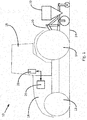
Fig. 1 is an illustration of an agricultural vehicle having a hitch-mounted implement according to an embodiment of the invention, and -
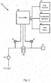
Fig. 2 is an illustrative schematic of a control system according to the invention. - In
Fig. 1 , a vehicle in the form of an agricultural tractor is indicated at 10. Thetractor 10 comprisesfront wheels 12,rear wheels 14, anengine section 16 and acab section 18. Thetractor 10 further comprises arear hitch 20 which may be raised or lowered relative to the rest of thetractor 10. An agricultural implement, in this case apneumatic seeder 22, can be provided mounted to thehitch 20, such that lowering or raising of thehitch 20 brings the hitch-mountedimplement 22 into or out of engagement with theground 24. Thetractor 10 further comprises at least one Electronic Control Unit (ECU) 26, which is arranged to control operation of various tractor systems. Thecab section 18 is provided withoperator controls 28 for control of the different components of thetractor 10, including the direct control of the height of thehitch 20. Theoperator controls 28 may comprise mechanical levers and/or electronic control systems incorporating configurable switches, touchscreen displays, etc. It will be understood that theECU 26 is provided in communication with theoperator controls 28. - The implement 22 acts as a hydraulic consumer, in that a supply of hydraulic fluid is needed for implement operation. It will be understood that the
tractor 10 further comprises a hydraulic circuit including a hydraulic supply, which can be releasably connected with the implement 22. - With reference to the schematic illustration of
Fig. 2 , a system according to the invention is indicated generally at 30. Thetractor 10 comprises a hydraulic tank orreservoir 32 coupled with apump 34. Thetank 32 and pump 34 are coupled to the hitch-mounted implement 22 through anadjustable fluid valve 36, such as a spool valve. It will be understood that thetank 32 and pump 34 may be coupled with additional hydraulic circuits or devices, which are not shown inFig. 2 . - The
system 30 further comprises acontroller 38 which is coupled with theadjustable valve 36 to control the flow of hydraulic fluid between thetank 32 and pump 34 and the implement 22. Thecontroller 38 may be provided as part of theECU 26 or as a separate controller element, e.g. as part of a retrofit solution. - First and second
fluid pressure sensors system 30, thepressure sensors controller 38. Thefirst pressure sensor 40 is positioned at the tank-facing side of thefluid valve 36, and is arranged to monitor the fluid pressure entering thevalve 36 from thetank 32 andpump 34. Thesecond pressure sensor 42 is positioned at the implement-facing side of thefluid valve 36, and is arranged to monitor the fluid pressure going from thevalve 36 to the implement 22. - Based on the monitored pressure levels, the
controller 38 is able to determine the fluid flow level through thevalve 36. The operation of thevalve 36 can then be controlled to adjust the fluid flow level to a desired level of flow for the hydraulic consumer in the form of the implement 22. For instances where thevalve 36 is a spool valve or similar, thecontroller 38 is operable to adjust the duty cycle of thevalve 36 to produce the desired flow level through thevalve 36. - The desired flow level of fluid may be a user-definable value, which a user may input using the operator controls 28.
- Additionally or alternatively, the desired flow level of fluid may be provided based on an implement
identifier 44. In such a case, thecontrol system 30 may be operable to receive data defining the particular implement 22 provided on thetractor 10, which may then determine particular preferred variables of thecontrol system 30, e.g. the preferred or default hydraulic fluid flow required for the implement 22 to operate. For example, the implement 22 may be provided with an RFID tag or othersuitable identifier 44 which may be accessed and read by thecontroller 38, or accessed by analternative tractor ECU 26 and stored in a suitable readable memory device (not shown) which may be accessed and read by thecontroller 38. Additionally, the vehicle operator may be able to define the type of implement 22 provided through use of the operator input controls 28, such data subsequently stored in memory accessible by thecontroller 38. - In a further aspect, the
control system 30 may be provided withsuitable sensors 46 to determine the status of thetractor hitch 20, e.g. whether thehitch 20 is in a raised or lowered position. Thecontroller 38 can then be configured to regulate the hydraulic fluid flow to the implement 22, based on the configuration of thehitch 20. - For example, if the
hitch 20 is raised, this may be indicative of when thehitch 20 and attached implement 22 are configured for transport mode, in which hydraulic fluid is not required by the implement. Accordingly, thecontroller 38 may be configured to reduce or shut off hydraulic flow through thevalve 36 when thehitch 20 is in the raised position. Similarly, when thehitch sensor 46 indicates that thehitch 20 is lowered, or transitions from a raised to a lowered position, this may be indicative of when thehitch 20 and attached implement 22 are prepared for operation. At this point, thecontroller 38 may be configured to regulate thefluid valve 36 to provide the desired fluid flow level through thevalve 36 when thehitch 20 is in the lowered position. - Preferably, the controller is arranged to calculate the required valve opening size such that:

- S = Fluid valve aperture size;
- F = Desired flow rate;
- V = Fluid viscosity;
- P1 = Fluid pressure at tank-facing side of fluid valve; and
- P2 = Fluid pressure at implement-facing side of fluid valve.
- The viscosity of the hydraulic fluid may be predefined by the
controller 38, or may be a user-definable setting. - The system and method of the invention provides a simpler and more efficient mechanism for tractor operators to control hydraulic flow in agricultural systems. In addition, the system and method of the invention provides for a high degree of flexibility and customisability of vehicle operation, when providing for hydraulic fluid control for tractor implements.
- The invention is not limited to the embodiments described herein, and may be modified or adapted without departing from the scope of the present invention.
Claims (15)
- An agricultural system comprising:an agricultural vehicle, preferably an agricultural tractor, having a hydraulic fluid tank;a hydraulically-operated agricultural implement coupled to the agricultural vehicle;an adjustable fluid valve connecting the hydraulic fluid tank with the agricultural implement;a first fluid pressure sensor located at the tank-facing side of the fluid valve;a second fluid pressure sensor located at the implement-facing side of the fluid valve; anda controller coupled with the fluid valve and the first and second pressure sensors, the controller operable to adjust the fluid valve such that the flow rate to the implement is maintained at a desired flow rate, and wherein the controller is operable to determine the actual flow rate of hydraulic fluid through the fluid valve based on the output of the first and second pressure sensors.
- The system of claim 1, wherein the adjustable fluid valve is a spool valve, and wherein the controller is operable to adjust the duty cycle of the spool valve.
- The system of claim 1 or claim 2, wherein the hydraulic fluid tank is provided as part of a hydraulic circuit of the agricultural vehicle.
- The system of claim 3, wherein the hydraulic circuit comprises a Load Sensing hydraulic circuit or an Open Centre hydraulic circuit.
- The system of any preceding claim, wherein the agricultural system further comprises an input device coupled with said controller, wherein a desired flow rate of hydraulic fluid through the fluid valve to the implement can be defined using said input device.
- The system of any preceding claim, wherein said agricultural implement is provided with an implement identifier, wherein the controller is operable to adjust the fluid valve based at least in part on said implement identifier.
- The system of claim 6, wherein said implement identifier comprises a machine-readable element, arranged to be accessed by the controller.
- The system of any preceding claim, wherein the agricultural vehicle comprises an adjustable hitch, wherein the implement is a hitch-mounted implement, and wherein the controller is operable to adjust the fluid valve to control the fluid flow rate based on the position of the adjustable hitch.
- The system of claim 8, wherein the controller is operable to determine if the hitch is in a raised or in a lowered position, wherein the fluid flow rate is controlled based on the position of the hitch and the hitch-mounted implement.
- The system of claim 9, wherein the controller is arranged to control the fluid valve to turn off fluid flow to the implement when the hitch is in a raised position.
- The system of any preceding claim, wherein the vehicle comprises a releasable fluid connection through which the hydraulic tank is connected with the implement, wherein the second fluid pressure sensor is positioned to measure the fluid pressure between the adjustable fluid valve and the releasable connection.
- The system of any preceding claim, wherein the controller is arranged to calculate the required valve opening size such that:
 S = Fluid valve aperture size;F = Desired flow rate;V = Fluid viscosity;P1 = Fluid pressure at tank-facing side of fluid valve; andP2 = Fluid pressure at implement-facing side of fluid valve.
 - A method of controlling the flow of hydraulic fluid between a hydraulic fluid tank and an agricultural implement through an adjustable fluid valve, the method comprising the steps of:receiving a desired fluid flow rate for an agricultural implement;measuring a first fluid pressure at the hydraulic tank-facing side of a fluid valve;measuring a second fluid pressure at the implement-facing side of the fluid valve;based on the first and second measured fluid pressures, determining the actual flow rate of hydraulic fluid through the fluid valve; andadjusting the fluid valve such that the actual flow rate equals the desired flow rate.
- The method of claim 13, wherein the step of receiving a desired fluid flow rate comprises providing an input device to a user, and receiving a user-defined fluid flow rate via said input device.
- A controller for an agricultural vehicle, the controller arranged to implement the steps as claimed in claim 13 or claim 14.
Applications Claiming Priority (1)
| Application Number | Priority Date | Filing Date | Title |
|---|---|---|---|
| EP16290038 | 2016-02-18 |
Publications (1)
| Publication Number | Publication Date |
|---|---|
| EP3211250A1 true EP3211250A1 (en) | 2017-08-30 |
Family
ID=55521646
Family Applications (1)
| Application Number | Title | Priority Date | Filing Date |
|---|---|---|---|
| EP17152847.4A Withdrawn EP3211250A1 (en) | 2016-02-18 | 2017-01-24 | A system and method for hydraulic flow control |
Country Status (2)
| Country | Link |
|---|---|
| US (1) | US20170241447A1 (en) |
| EP (1) | EP3211250A1 (en) |
Cited By (1)
| Publication number | Priority date | Publication date | Assignee | Title |
|---|---|---|---|---|
| CN113107913A (en) * | 2020-01-09 | 2021-07-13 | 罗伯特·博世有限公司 | Control device for a hydraulic unit with a plurality of receivers operating in parallel |
Families Citing this family (2)
| Publication number | Priority date | Publication date | Assignee | Title |
|---|---|---|---|---|
| JP2018084286A (en) * | 2016-11-24 | 2018-05-31 | 川崎重工業株式会社 | Operating device and hydraulic system |
| EP4508958B1 (en) * | 2023-08-18 | 2026-05-06 | Reinhold Schulte | Method for equipping or retrofitting an agricultural working vehicle with an implement |
Citations (3)
| Publication number | Priority date | Publication date | Assignee | Title |
|---|---|---|---|---|
| US6061617A (en) * | 1997-10-21 | 2000-05-09 | Case Corporation | Adaptable controller for work vehicle attachments |
| US6286412B1 (en) * | 1999-11-22 | 2001-09-11 | Caterpillar Inc. | Method and system for electrohydraulic valve control |
| US20030121409A1 (en) * | 2001-12-28 | 2003-07-03 | Caterpillar Inc. | System and method for controlling hydraulic flow |
-
2017
- 2017-01-24 EP EP17152847.4A patent/EP3211250A1/en not_active Withdrawn
- 2017-02-07 US US15/426,933 patent/US20170241447A1/en not_active Abandoned
Patent Citations (3)
| Publication number | Priority date | Publication date | Assignee | Title |
|---|---|---|---|---|
| US6061617A (en) * | 1997-10-21 | 2000-05-09 | Case Corporation | Adaptable controller for work vehicle attachments |
| US6286412B1 (en) * | 1999-11-22 | 2001-09-11 | Caterpillar Inc. | Method and system for electrohydraulic valve control |
| US20030121409A1 (en) * | 2001-12-28 | 2003-07-03 | Caterpillar Inc. | System and method for controlling hydraulic flow |
Cited By (1)
| Publication number | Priority date | Publication date | Assignee | Title |
|---|---|---|---|---|
| CN113107913A (en) * | 2020-01-09 | 2021-07-13 | 罗伯特·博世有限公司 | Control device for a hydraulic unit with a plurality of receivers operating in parallel |
Also Published As
| Publication number | Publication date |
|---|---|
| US20170241447A1 (en) | 2017-08-24 |
Similar Documents
| Publication | Publication Date | Title |
|---|---|---|
| US9615499B2 (en) | Hydraulic work unit leveling and calibration system for an agricultural implement | |
| US10562358B2 (en) | Device for tire pressure monitoring of a vehicle system | |
| US6058342A (en) | Precision control of implement position/motion | |
| US8235130B2 (en) | Method and apparatus for controlling the depth of an agricultural work unit mounted to a frame that can be raised and lowered by a cylinder assembly | |
| US5810095A (en) | System for controlling the position of an implement attached to a work vehicle | |
| EP2676535B1 (en) | Position and pressure depth control system for an agricultural implement | |
| US6058343A (en) | Threshold current control system for hydraulic valves | |
| EP1889531B1 (en) | Using a CAN bus engine torque/speed message as load feedback | |
| EP2205056B1 (en) | Adaptive feedback sources for application controllers | |
| KR101801991B1 (en) | Out-of-range sensor recalibration | |
| US11526171B2 (en) | Method for operating a system made up of an agricultural working vehicle and at least one working tool arranged thereon | |
| US12035650B2 (en) | Control system and method for operating an agricultural machine as well as an agricultural machine | |
| US20170241447A1 (en) | System and method for hydraulic flow control | |
| US11533901B2 (en) | Traveling vehicle | |
| US11326592B2 (en) | Method for operating a hydraulic consumer on an electrically actuated control valve | |
| US11174621B2 (en) | Implement and a method for obtaining information related to said implement | |
| US6561076B2 (en) | Differential configuration of remote hydraulic valve flow rates for extend and retract modes of operation | |
| EP3207782A2 (en) | A system and method for hitch control | |
| US7025148B2 (en) | Vehicle with an attachment | |
| EP4548734A1 (en) | Work device diagnosis system, agricultural machine, agricultural work assistance system | |
| EP3311035B1 (en) | Agricultural implement and method of supplying hydraulic power to an agricultural implement | |
| US12336529B2 (en) | System and method for an agricultural applicator | |
| EP4014709A1 (en) | Agricultural apparatus with cutting height control | |
| JP4568349B2 (en) | Agricultural tractor with implement | |
| JP4568295B2 (en) | Agricultural tractor |
Legal Events
| Date | Code | Title | Description |
|---|---|---|---|
| PUAI | Public reference made under article 153(3) epc to a published international application that has entered the european phase |
Free format text: ORIGINAL CODE: 0009012 |
|
| STAA | Information on the status of an ep patent application or granted ep patent |
Free format text: STATUS: THE APPLICATION HAS BEEN PUBLISHED |
|
| AK | Designated contracting states |
Kind code of ref document: A1 Designated state(s): AL AT BE BG CH CY CZ DE DK EE ES FI FR GB GR HR HU IE IS IT LI LT LU LV MC MK MT NL NO PL PT RO RS SE SI SK SM TR |
|
| AX | Request for extension of the european patent |
Extension state: BA ME |
|
| STAA | Information on the status of an ep patent application or granted ep patent |
Free format text: STATUS: REQUEST FOR EXAMINATION WAS MADE |
|
| 17P | Request for examination filed |
Effective date: 20180228 |
|
| RBV | Designated contracting states (corrected) |
Designated state(s): AL AT BE BG CH CY CZ DE DK EE ES FI FR GB GR HR HU IE IS IT LI LT LU LV MC MK MT NL NO PL PT RO RS SE SI SK SM TR |
|
| STAA | Information on the status of an ep patent application or granted ep patent |
Free format text: STATUS: THE APPLICATION IS DEEMED TO BE WITHDRAWN |
|
| 18D | Application deemed to be withdrawn |
Effective date: 20180301 |