EP3211221A1 - Internal ladder assembly for a wind turbine rotor hub - Google Patents
Internal ladder assembly for a wind turbine rotor hub Download PDFInfo
- Publication number
- EP3211221A1 EP3211221A1 EP17157008.8A EP17157008A EP3211221A1 EP 3211221 A1 EP3211221 A1 EP 3211221A1 EP 17157008 A EP17157008 A EP 17157008A EP 3211221 A1 EP3211221 A1 EP 3211221A1
- Authority
- EP
- European Patent Office
- Prior art keywords
- platform
- hub
- rotor hub
- ladder
- platforms
- Prior art date
- Legal status (The legal status is an assumption and is not a legal conclusion. Google has not performed a legal analysis and makes no representation as to the accuracy of the status listed.)
- Granted
Links
Images




Classifications
-
- E—FIXED CONSTRUCTIONS
- E06—DOORS, WINDOWS, SHUTTERS, OR ROLLER BLINDS IN GENERAL; LADDERS
- E06C—LADDERS
- E06C9/00—Ladders characterised by being permanently attached to fixed structures, e.g. fire escapes
- E06C9/02—Ladders characterised by being permanently attached to fixed structures, e.g. fire escapes rigidly mounted
-
- F—MECHANICAL ENGINEERING; LIGHTING; HEATING; WEAPONS; BLASTING
- F03—MACHINES OR ENGINES FOR LIQUIDS; WIND, SPRING, OR WEIGHT MOTORS; PRODUCING MECHANICAL POWER OR A REACTIVE PROPULSIVE THRUST, NOT OTHERWISE PROVIDED FOR
- F03D—WIND MOTORS
- F03D1/00—Wind motors with rotation axis substantially parallel to the air flow entering the rotor
- F03D1/06—Rotors
- F03D1/065—Rotors characterised by their construction elements
- F03D1/0691—Rotors characterised by their construction elements of the hub
-
- E—FIXED CONSTRUCTIONS
- E02—HYDRAULIC ENGINEERING; FOUNDATIONS; SOIL SHIFTING
- E02D—FOUNDATIONS; EXCAVATIONS; EMBANKMENTS; UNDERGROUND OR UNDERWATER STRUCTURES
- E02D27/00—Foundations as substructures
- E02D27/32—Foundations for special purposes
- E02D27/42—Foundations for poles, masts or chimneys
- E02D27/425—Foundations for poles, masts or chimneys specially adapted for wind motors masts
-
- E—FIXED CONSTRUCTIONS
- E04—BUILDING
- E04H—BUILDINGS OR LIKE STRUCTURES FOR PARTICULAR PURPOSES; SWIMMING OR SPLASH BATHS OR POOLS; MASTS; FENCING; TENTS OR CANOPIES, IN GENERAL
- E04H12/00—Towers; Masts or poles; Chimney stacks; Water-towers; Methods of erecting such structures
- E04H12/02—Structures made of specified materials
- E04H12/08—Structures made of specified materials of metal
-
- F—MECHANICAL ENGINEERING; LIGHTING; HEATING; WEAPONS; BLASTING
- F03—MACHINES OR ENGINES FOR LIQUIDS; WIND, SPRING, OR WEIGHT MOTORS; PRODUCING MECHANICAL POWER OR A REACTIVE PROPULSIVE THRUST, NOT OTHERWISE PROVIDED FOR
- F03D—WIND MOTORS
- F03D80/00—Details, components or accessories not provided for in groups F03D1/00 - F03D17/00
- F03D80/50—Maintenance or repair
-
- E—FIXED CONSTRUCTIONS
- E02—HYDRAULIC ENGINEERING; FOUNDATIONS; SOIL SHIFTING
- E02D—FOUNDATIONS; EXCAVATIONS; EMBANKMENTS; UNDERGROUND OR UNDERWATER STRUCTURES
- E02D27/00—Foundations as substructures
- E02D27/32—Foundations for special purposes
- E02D27/42—Foundations for poles, masts or chimneys
-
- E—FIXED CONSTRUCTIONS
- E04—BUILDING
- E04G—SCAFFOLDING; FORMS; SHUTTERING; BUILDING IMPLEMENTS OR AIDS, OR THEIR USE; HANDLING BUILDING MATERIALS ON THE SITE; REPAIRING, BREAKING-UP OR OTHER WORK ON EXISTING BUILDINGS
- E04G3/00—Scaffolds essentially supported by building constructions, e.g. adjustable in height
- E04G3/24—Scaffolds essentially supported by building constructions, e.g. adjustable in height specially adapted for particular parts of buildings or for buildings of particular shape, e.g. chimney stacks or pylons
- E04G3/246—Scaffolds essentially supported by building constructions, e.g. adjustable in height specially adapted for particular parts of buildings or for buildings of particular shape, e.g. chimney stacks or pylons following the inside contour of a building
-
- F—MECHANICAL ENGINEERING; LIGHTING; HEATING; WEAPONS; BLASTING
- F03—MACHINES OR ENGINES FOR LIQUIDS; WIND, SPRING, OR WEIGHT MOTORS; PRODUCING MECHANICAL POWER OR A REACTIVE PROPULSIVE THRUST, NOT OTHERWISE PROVIDED FOR
- F03D—WIND MOTORS
- F03D13/00—Assembly, mounting or commissioning of wind motors; Arrangements specially adapted for transporting wind motor components
- F03D13/10—Assembly of wind motors; Arrangements for erecting wind motors
-
- F—MECHANICAL ENGINEERING; LIGHTING; HEATING; WEAPONS; BLASTING
- F03—MACHINES OR ENGINES FOR LIQUIDS; WIND, SPRING, OR WEIGHT MOTORS; PRODUCING MECHANICAL POWER OR A REACTIVE PROPULSIVE THRUST, NOT OTHERWISE PROVIDED FOR
- F03D—WIND MOTORS
- F03D13/00—Assembly, mounting or commissioning of wind motors; Arrangements specially adapted for transporting wind motor components
- F03D13/20—Arrangements for mounting or supporting wind motors; Masts or towers for wind motors
-
- F—MECHANICAL ENGINEERING; LIGHTING; HEATING; WEAPONS; BLASTING
- F03—MACHINES OR ENGINES FOR LIQUIDS; WIND, SPRING, OR WEIGHT MOTORS; PRODUCING MECHANICAL POWER OR A REACTIVE PROPULSIVE THRUST, NOT OTHERWISE PROVIDED FOR
- F03D—WIND MOTORS
- F03D13/00—Assembly, mounting or commissioning of wind motors; Arrangements specially adapted for transporting wind motor components
- F03D13/40—Arrangements or methods specially adapted for transporting wind motor components
-
- Y—GENERAL TAGGING OF NEW TECHNOLOGICAL DEVELOPMENTS; GENERAL TAGGING OF CROSS-SECTIONAL TECHNOLOGIES SPANNING OVER SEVERAL SECTIONS OF THE IPC; TECHNICAL SUBJECTS COVERED BY FORMER USPC CROSS-REFERENCE ART COLLECTIONS [XRACs] AND DIGESTS
- Y02—TECHNOLOGIES OR APPLICATIONS FOR MITIGATION OR ADAPTATION AGAINST CLIMATE CHANGE
- Y02E—REDUCTION OF GREENHOUSE GAS [GHG] EMISSIONS, RELATED TO ENERGY GENERATION, TRANSMISSION OR DISTRIBUTION
- Y02E10/00—Energy generation through renewable energy sources
- Y02E10/70—Wind energy
- Y02E10/72—Wind turbines with rotation axis in wind direction
-
- Y—GENERAL TAGGING OF NEW TECHNOLOGICAL DEVELOPMENTS; GENERAL TAGGING OF CROSS-SECTIONAL TECHNOLOGIES SPANNING OVER SEVERAL SECTIONS OF THE IPC; TECHNICAL SUBJECTS COVERED BY FORMER USPC CROSS-REFERENCE ART COLLECTIONS [XRACs] AND DIGESTS
- Y02—TECHNOLOGIES OR APPLICATIONS FOR MITIGATION OR ADAPTATION AGAINST CLIMATE CHANGE
- Y02E—REDUCTION OF GREENHOUSE GAS [GHG] EMISSIONS, RELATED TO ENERGY GENERATION, TRANSMISSION OR DISTRIBUTION
- Y02E10/00—Energy generation through renewable energy sources
- Y02E10/70—Wind energy
- Y02E10/728—Onshore wind turbines
Definitions
- the present subject matter relates generally to wind turbines and, more particularly, to an internal ladder assembly for a wind turbine rotor hub that allows service personnel to access the interior of the rotor hub through rear access ports defined through the hub.
- a modem wind turbine typically includes a tower, generator, gearbox, nacelle, rotor hub and one or more rotor blades.
- the rotor blades capture kinetic energy of the wind using known airfoil principles.
- the rotor blades transmit the kinetic energy in the form of rotational energy to turn a shaft coupling the rotor blades to a gearbox, or if a gearbox is not used, directly to the generator.
- the generator then converts the mechanical energy to electrical energy that may be deployed to a utility grid.
- a service worker In order to perform certain types of maintenance on the rotor hub, the rotor blades and/or various other components of the wind turbine, a service worker must gain internal access to the rotor hub. Typically, such access is gained through an access port located at the front end of the rotor hub (i.e., the end of the rotor hub furthest away from the nacelle). Thus, to reach the access port, a service worker must typically climb onto the top of the nacelle, move over to the top of the rotor hub and repel or climb down the front of the rotor hub. Unfortunately, since the service worker must climb outside the wind turbine and over the top of the rotor hub, significant safety risks are associated with gaining access to the interior of the hub.
- the present subject matter is directed to a rotor hub for a wind turbine.
- the rotor hub may generally include a hub body extending between a forward end and an aft end.
- the hub body may define a plurality of blade flanges between the forward and aft ends.
- the hub body may also define a plurality of access ports spaced apart from the blade flanges.
- the rotor hub may include a ladder assembly extending within an interior of the hub body.
- the ladder assembly may include a plurality of platforms, with each platform being positioned within the interior of the rotor hub so as to be circumferentially aligned with a respective one of the plurality of access ports. Each platform may also define a planar surface.
- the ladder assembly may further include a connecting frame extending between each pair of adjacent platforms so as to couple the adjacent platforms to one another.
- the connecting frame may extend lengthwise along a reference line defined between the adjacent platforms.
- the platforms may be positioned relative to one another such that the reference line extends at a non-perpendicular angle relative to the planar surfaces defined by the adjacent platforms.
- the present subject matter is directed to an internal ladder assembly for a rotor hub of a wind turbine.
- the ladder assembly may generally include a plurality of platforms spaced apart circumferentially from one another. Each platform may define a planar surface extending lengthwise between a first end and a second end.
- the platforms may include a first platform, a second platform and a third platform.
- the ladder assembly may also include at least one first frame member extending outwardly from the first platform, at least one second frame member extending outwardly from the second platform and at least one third frame member extending outwardly from the third platform.
- Each of the first, second and third frame members may be oriented at a non-perpendicular angle relative to the planar surface defined by the respective platform from which the first, second or third frame members extends.
- the present subject matter is directed to a rotor hub for a wind turbine.
- the rotor hub may generally include a hub body extending between a forward end and an aft end.
- the hub body may define a plurality of blade flanges between the forward and aft ends.
- the hub body may also define a plurality of access ports spaced apart from the blade flanges.
- the rotor hub may include a ladder assembly extending within an interior of the hub body.
- the ladder assembly may include a plurality of ladder sub-assemblies, with each ladder sub-assembly being positioned at least partially within the interior of the rotor hub so as to be circumferentially aligned with a respective one of the plurality of access ports.
- Each ladder sub-assembly may include a first ladder support, a second ladder support and at least one ladder rung extending between the first and second ladder supports.
- the ladder assembly may also include a connecting frame extending between each pair of adjacent ladder sub-assemblies so as to couple the adjacent ladder sub-assemblies to one another.
- the connecting frame may extend lengthwise along a reference line defined between the adjacent ladder sub-assemblies.
- the ladder assembly may include at least one foot support member extending from the connecting frame.
- the present subject matter is directed to a rotor hub for a wind turbine having an internal ladder assembly installed therein for allowing service personnel to quickly and easily gain access to the interior of the hub.
- the ladder assembly may include a plurality of ladder sub-assemblies mounted within the hub, with each ladder sub-assembly being circumferentially aligned with a different access port defined through the body of the hub.
- the rotor hub may include three access ports spaced apart circumferentially from one another (e.g., by 120 degrees).
- the ladder assembly may include three ladder sub-assemblies such that each sub-assembly is mounted within the hub adjacent to the location of one of the access ports.
- the ladder assembly may also include a plurality of connecting frames, with each connecting frame being coupled between an adjacent pair of ladder sub-assemblies such that the sub-assemblies are coupled to one another within the interior of the hub.
- the connecting frames may also be configured to form steps between each adjacent pair of ladder sub-assemblies.
- the hub may be rotated such that one of the access ports is vertically oriented, thereby allowing a service worker to insert his/her legs through the access port from a top side of the hub and support himself/herself on the ladder sub-assembly positioned directly adjacent to such access port.
- the service worker may then utilize the step(s) formed by the connecting frames extending from the ladder sub-assembly on which he/she is standing to climb down into the hub.
- each ladder sub-assembly may include a standing/stepping platform.
- the platforms of the sub-assemblies may be positioned within the hub relative to one another such that each connecting frame extends between adjacent platforms at a non-perpendicular angle relative to the planar surfaces defined by the adjacent platforms.
- the connecting frames coupled to a given ladder sub-assembly may extend from its corresponding platform at an obtuse angle such that the connecting frames diverge outwardly as they extend away from the platform.
- the platforms may be positioned within the hub relative to one another such that each connecting frame extends lengthwise between each pair of adjacent platforms along a reference line that is oriented parallel to an adjacent blade flange of the hub.
- each connecting frame extends lengthwise between each pair of adjacent platforms along a reference line that is oriented parallel to an adjacent blade flange of the hub.
- FIG. 1 illustrates a side view of one embodiment of a wind turbine 10.
- the wind turbine 10 generally includes a tower 12 extending from a support surface 14 (e.g., the ground, a concrete pad or any other suitable support surface).
- the wind turbine 10 may also include a nacelle 16 mounted on the tower 12 and a rotor 18 coupled to the nacelle 16.
- the rotor 18 includes a rotatable hub 20 and at least one rotor blade 22 coupled to and extending outwardly from the hub 20.
- the rotor 18 includes three rotor blades 22.
- the rotor 18 may include more or less than three rotor blades 22.
- Each rotor blade 22 may be spaced about the hub 20 to facilitate rotating the rotor 18 to enable kinetic energy to be transferred from the wind into usable mechanical energy, and subsequently, electrical energy.
- the hub 20 may be rotatably coupled to an electric generator (not shown) positioned within the nacelle 16 to permit electrical energy to be produced.
- the rotor hub 100 may have any suitable configuration that allows the hub 100 to couple the rotor blades 22 of the wind turbine 10 to a corresponding rotor shaft (not shown) of the turbine 10.
- the rotor hub 100 may include a hollow body 102 extending axially between a first end 104 and a second end 106.
- the first end 104 may generally correspond to the forward end of the rotor hub 100 (i.e., the end furthest away from the nacelle 16 when the rotor hub 100 is disposed in its assembled position on a wind turbine 10) and the second end 106 may generally correspond to the aft end of the rotor hub 100 (i.e., the end closest to the nacelle 16 when the rotor hub 100 is disposed in its assembled position on a wind turbine 10).
- a shaft opening 108 may be defined at the second end 106 of the hub body 102.
- a portion of the rotor shaft (not shown) of the wind turbine 10 may be coupled to the hub 100 at the shaft opening 108 (e.g., by coupling the rotor shaft to a shaft flange 110 defined around the outer perimeter of the shaft opening 108) to facilitate rotatably mounting the hub 100 to the shaft.
- the rotor hub 100 may also include a plurality of blade flanges 112 spaced apart around its outer perimeter.
- the number of blade flanges 112 may correspond to the number of rotor blades 22 of the wind turbine 10.
- the rotor hub 100 may include three blade flanges 112, with each blade flange 112 being generally equally spaced apart circumferentially from adjacent blade flanges (e.g., by approximately 120 degrees).
- Each blade flange 112 may generally be configured to be coupled to one of the rotor blades 22 via a pitch bearing (not shown) of the wind turbine 10.
- each blade flange 112 may define a generally planar mounting surface 114 to which a suitable pitch bearing may be secured (e.g., using bolts and/or any other suitable fastening mechanisms).
- the rotor hub 100 may also include one or more stiffening webs 116 extending across an opening 118 defined by each blade flange 112.
- the stiffening web(s) 116 may be configured to increase the structural stiffness and rigidity of the rotor hub 100 at and/or adjacent to each blade flange 112.
- one or more hub access ports 120 may also be defined in the hub body 102.
- three access ports 120 may be defined in the hub body 102 at a location adjacent to the aft or second end 116 of the hub 100, such as by positioning the access ports 120 at an axial location generally between the shaft opening 108 and the blade flanges 112.
- the access ports 120 may be spaced apart around the outer perimeter of the hub body 102 so as to have any suitable circumferential spacing, such as by spacing the access ports 120 apart from one another equally (e.g., by approximately 120 degrees).
- the access ports 120 are equally spaced from one another and generally circumferentially offset from the blade flanges 112 such that the center of each access port 120 is spaced apart circumferentially from the centers of the adjacent blade flanges 112 by approximately 60 degrees.
- the hub access ports 120 may generally be configured to permit a service worker to gain access to the interior of the rotor hub 100.
- the access ports 120 may be sized such that a person may travel through each access port 120.
- a front access port 122 may also be defined at the forward or first end 104 of the rotor hub 100.
- the front access port 122 may also be utilized to gain access to the interior of the rotor hub 100.
- the front access port 122 may be utilized to receive and/or remove heavy or large components from the hub 100 and/or to provide emergency access to the interior of the hub 100.
- the hollow body 102 of the rotor hub 100 may be formed as a single component, such as by casting the body 102 using any suitable casting process and material.
- the body 102 of the rotor hub 100 may be formed from a plurality of components, such as by forming the body 102 as a plurality of hub segments configured to be assembled together to form the overall shape and configuration of the rotor hub 100.
- FIGS. 3-6 several views of one embodiment of a ladder assembly 200 that may be installed within a rotor hub of a wind turbine 10 to assist service personnel in gaining access to the interior of the hub 100 are illustrated in accordance with aspects of the present subject matter.
- FIG. 3 illustrates a perspective, assembled view of the ladder assembly 200
- FIG. 4 illustrates a perspective, exploded view of the ladder assembly 200 shown in FIG. 3 .
- FIG. 5 illustrates a perspective, internal view of the rotor hub 100 shown in FIG. 2 with the ladder assembly 200 shown in FIGS. 3 and 4 installed therein, particularly illustrating a portion of the hub 100 being cut-away for purposes of illustration.
- FIG. 6 illustrates front-to-back axial view of the rotor hub 100 and the ladder assembly 200 shown in FIG. 5 .
- the ladder assembly 200 may be configured to be installed within the interior of the rotor hub 100 such that service personnel accessing the hub 100 through one of the access ports 120 may climb down into the hub 100 both safely and efficiently.
- the hub 100 may be rotated relative to the nacelle 16 of the wind turbine 10 such that one of the access ports 120 is positioned at the twelve o'clock rotor position (e.g., similar to the access port 120 shown at the top of FIG. 6 ).
- a service worker located on the nacelle 16 may access the interior of the hub 100 via the access port 120 positioned at the twelve o'clock rotor position. The service worker may then utilize the internal ladder assembly 200 to climb down into the hub.
- the ladder assembly 200 may, in several embodiments, include a plurality of platforms 202, 204, 206 configured to provide a stable standing/stepping surface for service personnel initially entering the rotor hub 100 via one of the access ports 120.
- the ladder assembly 200 may similarly include three standing/stepping platforms 202, 204, 206, with each platform configured to be positioned within the hub 100 so as to be circumferentially aligned with one of the access ports 120. For example, as shown in FIG.
- a first platform 202 of the ladder assembly 200 may be installed within the rotor hub 100 so as to be circumferentially aligned with the first access port 120A, such as by aligning the platform 202 with a centerline 208A of the first access port 120A.
- second and third platforms 204, 206 of the ladder assembly 200 may be installed within the rotor hub 100 so as to be circumferentially aligned with the second and third access ports 120B, 120C, respectively, such as aligning the platforms 204, 206 with respective centerlines 208B, 208C of the corresponding access ports 120B, 120C.
- a center of each platform 202, 204, 206 may be circumferentially aligned with the centerline 208A, 208B, 208C of its corresponding access port 120A, 120B, 120C.
- the centers of the platforms 202, 204, 206 may be similarly spaced apart circumferentially from one another by 120 degrees within the interior of the rotor hub 102.
- the platforms 202, 204, 206 may be positioned radially outwardly from a rotational axis 210 ( FIG. 6 ) of the hub 100 such that each platform 202, 204, 206 may be easily accessed from its corresponding access port 120A, 120B, 120C.
- the platforms 202, 204, 206 are generally radially aligned with the outer perimeter of the shaft opening 108.
- a service worker entering the hub 100 through one of the access ports 120 may immediately place his/her foot onto the adjacent platform 202, 204, 206 to assist the worker in climbing down into the hub 100.
- the service worker may have a safety cable coupled to the nacelle 16.
- the hooking point of the safety cable may be moved to a location within the interior of the hub 100.
- the service worker may safely stand on the platform 202, 204, 206 as he/she moves the hooking point of the safety cable.
- each platform 202, 204, 206 may generally extend lengthwise between a first end 212 and a second end 214.
- each platform 202, 204, 206 may define a planar surface 216 extending between its first and second ends 212, 214.
- the platforms 202, 204, 206 may be oriented relative to the access ports 120A, 120B, 120C such that the planar surface 216 defined by each platform 202, 204, 206 extends generally perpendicular to the centerline 208A, 208B, 208C of its corresponding access port 120A, 120B, 120C.
- the ladder assembly 200 may also include first and second ladder supports 218, 220 extending outwardly from each platform 202, 204, 206 in the direction of the adjacent access port 120A, 120B, 120C.
- Each pair of ladder supports 218, 220 may be configured to support one or more ladder rungs 222 at a radial location between the adjacent platform 202, 204, 206 and its corresponding access port 120A, 120B, 120C.
- each ladder rung 222 may extend perpendicularly between its corresponding ladder supports 218.
- the ladder assembly 200 may, instead, include two or more ladder rungs 222 extending between each pair of ladder supports 218, 220.
- the ladder assembly 200 may include a plurality of radially spaced ladder rungs 222 extending between each pair of ladder supports 218, 220.
- each platform 202, 204, 206 and its corresponding ladder supports 218, 220 and ladder rung(s) 220 may form all or part of a ladder sub-assembly 201 of the ladder assembly 200.
- the ladder assembly 200 may include three ladder sub-assemblies 201 configured to be installed within the interior of the hub 100.
- the ladder sub-assemblies 201 may be configured to be coupled to one another within the interior of the hub 100 to form a closed-shaped structure or assembly.
- the ladder sub-assemblies 201 may be mounted separately within the interior of the hub 100 without being coupled to one another.
- the ladder assembly 200 may also include a connecting frame 224, 226, 228 extending between each pair of adjacent platforms 202, 204, 206 in order to couple the platforms 202, 204, 206 (and, thus, the ladder sub-assemblies 201) to one another within the interior of the hub 100.
- the ladder assembly 200 includes a first connecting frame 224 coupled between the second end 214 of the first platform 202 and the first end 212 of the second platform 204.
- the ladder assembly 200 includes a second connecting frame 226 coupled between the first end 212 of the first platform 202 and the second end 214 of the third platform 26 and a third connecting frame 228 coupled between the second end 214 of the second platform 204 and the first end 212 of the third platform 206.
- the connecting frames 224, 226, 228 and the platforms 202, 204, 206 may form a closed-shaped structure or assembly.
- each connecting frame 224, 226, 228 may be formed by one or more frame members coupled to one another along the length of the connecting frame 224, 226, 228.
- a first outer frame member 230 is configured to extend outwardly from the first end 212 of each platform 224, 226, 228 and a second outer frame member 232 is configured to extend outwardly from the second end 214 of each platform 224, 226, 228.
- the ladder assembly 200 may include an intermediate frame member 234 configured to be coupled between the first outer frame member 230 of each stepping platform 202, 204, 206 and the second outer frame member 232 of the adjacent stepping platform 202, 204, 206.
- each intermediate frame member 234 may be coupled between its corresponding outer frame members 230, 232, a connecting frame 224, 226, 228 that extends between the adjacent platforms 202, 204, 206 to form the closed-shape structure of the ladder assembly 100.
- each connecting frame 224, 226, 228 may be formed from any other suitable number of frame members.
- each connecting frame 224, 226, 228 may be formed by a single frame member extending directly between the ends 212, 214 of adjacent stepping platforms 202, 204, 206.
- the frame members 230, 232 extending from each platform 202, 204, 206 may be coupled directly to the frame members 230, 232 of adjacent platforms 202, 204, 206 without the need for the intermediate frame members 234.
- each connecting frame 224, 226, 228 may include one or more foot support members 236 extending from the frame member(s) 230, 232, 234.
- each frame member 230, 232, 234 may include a foot support member 236 extending inwardly therefrom towards the center of the ladder assembly 200.
- each platform 202, 204, 206 may similarly include a foot support member 236 extending inwardly therefrom towards the center of the ladder assembly 200.
- the various foot support members 236 may be configured to serve as steps extending along the interior of the ladder assembly 200. As such, a service worker standing on one of the platforms 202, 204, 206 may step down onto one or more of the foot support members 236 as he/she climbs down into the rotor hub 100.
- the foot support members 236 may be configured to extend outwardly from the frame member(s) 230, 232, 234.
- FIG. 7 illustrates an alternative embodiment of the ladder assembly 200 shown in FIG. 5 in which the foot support members 236 extend outwardly from the frame member(s) 230, 232, 234 toward the exterior of the ladder assembly 200.
- the ladder assembly 200 may include foot support members 236 extending both inwardly and outwardly from the frame member(s) 230, 232, 234.
- each foot support member 236 may be configured to extend from its corresponding frame member 230, 232, 234 so as to define a closed-shape between the foot support member 236 and the adjacent frame member 230, 232, 234. As such, a service worker may place his/her foot within the interior of the closed-shape defined between each foot support member 236 and its corresponding frame member 230, 232, 234 when climbing down into the hub 100. As shown in the illustrated embodiment, each foot support member 236 is generally V-shaped such that a triangular closed-shape is defined between the foot support member 236 and its corresponding frame member 230, 232, 234. However, in other embodiments, each foot support member 236 may have any other suitable shape.
- the foot support members 236 may be configured to extend from the frame member(s) 230, 232, 234 without defining closed-shapes therebetween.
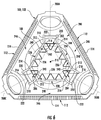
- FIG. 8 illustrates an alternative embodiment in which the foot support members 236 are configured as ladder rungs or posts extending outwardly from the frame member(s) 230, 232, 234. As shown in FIG. 8 , the foot support members 236 extend outwardly from the frame member(s) 230, 232, 234 in an axial direction of the rotor hub 100 (e.g., in a direction parallel to the rotational axis of the hub 100).
- foot support members 236 may be configured to extend radially relative to frame member(s) 230, 232, 234, such as by extending radially inwardly and/or radially outwardly from the frame member(s) 230, 232, 234.
- each connecting frame 224, 226, 228 may be configured to extend lengthwise between its corresponding platforms 202, 204, 206 along a reference line 240.
- each connecting frame 224, 226, 228 may extend lengthwise along a reference line 240 that is oriented at a non-perpendicular angle relative to the planar surfaces 216 defined by the platforms 202, 204, 206 between which the connecting frame 224, 226, 228 is coupled.
- the reference line 240 for each connecting frame 224, 226, 228 may be oriented relative to the adjacent stepping platforms202, 204, 206 such that an obtuse interior angle 242 is defined along the interior of the ladder assembly 200 at the intersection of each reference line 240 and the planar surface 216 defined by each platform 202, 204, 206.
- the connecting frames 224, 226, 228 coupled to a given platform 202, 204, 206 may diverge outwardly from one another as the connecting frames 224, 226, 228 extend from such platform 202, 204, 206 towards the adjacent platforms 202, 204, 206.
- the specific interior angles 242 defined between the reference lines 240 for the connecting frames 224, 226, 228 and the platforms 202, 204, 206 may generally vary depending on the installation locations and relative positioning of the platforms 202, 204, 206.
- the platforms 202, 204, 206 may be installed within the rotor hub 100 (e.g., at locations around the circumference of the shaft opening 108) such that the reference line 240 defined by each connecting frame 224, 226, 228 extends generally parallel to the blade mounting plane or planar mounting surface 114 defined by the adjacent blade flange 112.
- the ladder assembly 200 may define a significant amount of storage space or pass-through area.
- an internal area may be defined within the inner perimeter of the ladder assembly 200 that is formed by the radially inner ends of the foot support members 236. Such internal area 244 may be used for mounting and/or storing equipment and/or other wind turbine components.
- open spaces 246 may be defined within the interior of the rotor hub 100 between each connecting frame 224, 226, 228 and the adjacent blade flange 112 of the hub 100.
- Such open spaces 246 may provide sufficient room for positioning and/or manipulating tools and/or other devices relative to the adjacent blade flange 112.
- the open spaces 246 may provide sufficient room for performing pitch bearing maintenance, such as by allowing tools for checking the pitch bearing bolts to be inserted between each connecting frame 224, 226, 228 and the adjacent blade flange 114.
- each reference line 240 defined by the connecting frames 224, 226, 228 are shown as continuous straight lines.
- each reference line 240 may be curved such that each connecting frame 224, 226, 228 extends lengthwise between its adjacent platforms 202, 204, 206 along a curved or acruate path.
- each reference line 240 may be non-straight lines, such as by defining one or more line segments that are angled relative to one or more other line segments of the reference line 240.
- the frame members 230, 232, 234 forming each connecting frame 224, 226, 228 are shown as extending along a common reference line 240.
- one or more of the frame members 230, 232, 234 forming each connecting frame 224, 226, 228 may be configured to extend lengthwise along a reference line that differs from the reference line(s) associated with one or more of the other frame members 230, 232, 234 forming such connecting frame 224, 226, 228.
- each pair of ladder supports 218, 220 may be configured to extend radially from the corresponding platform 202, 204, 206 through the adjacent access port 120 to a location exterior of the hub 100.
- a plurality of ladder rungs 222 may be provided between the ladder supports 218, 220 to provide stepping surfaces for climbing down into the interior of the hub 100.
Landscapes
- Engineering & Computer Science (AREA)
- Life Sciences & Earth Sciences (AREA)
- Chemical & Material Sciences (AREA)
- Mechanical Engineering (AREA)
- General Engineering & Computer Science (AREA)
- Sustainable Development (AREA)
- Sustainable Energy (AREA)
- Combustion & Propulsion (AREA)
- Structural Engineering (AREA)
- Architecture (AREA)
- Civil Engineering (AREA)
- Wood Science & Technology (AREA)
- Materials Engineering (AREA)
- General Life Sciences & Earth Sciences (AREA)
- Mining & Mineral Resources (AREA)
- Paleontology (AREA)
- Wind Motors (AREA)
Abstract
Description
- The present subject matter relates generally to wind turbines and, more particularly, to an internal ladder assembly for a wind turbine rotor hub that allows service personnel to access the interior of the rotor hub through rear access ports defined through the hub.
- Wind power is considered one of the cleanest, most environmentally friendly energy sources presently available, and wind turbines have gained increased attention in this regard. A modem wind turbine typically includes a tower, generator, gearbox, nacelle, rotor hub and one or more rotor blades. The rotor blades capture kinetic energy of the wind using known airfoil principles. The rotor blades transmit the kinetic energy in the form of rotational energy to turn a shaft coupling the rotor blades to a gearbox, or if a gearbox is not used, directly to the generator. The generator then converts the mechanical energy to electrical energy that may be deployed to a utility grid.
- In order to perform certain types of maintenance on the rotor hub, the rotor blades and/or various other components of the wind turbine, a service worker must gain internal access to the rotor hub. Typically, such access is gained through an access port located at the front end of the rotor hub (i.e., the end of the rotor hub furthest away from the nacelle). Thus, to reach the access port, a service worker must typically climb onto the top of the nacelle, move over to the top of the rotor hub and repel or climb down the front of the rotor hub. Unfortunately, since the service worker must climb outside the wind turbine and over the top of the rotor hub, significant safety risks are associated with gaining access to the interior of the hub.
- Accordingly, a rotor hub and associated internal ladder assembly that allow a service worker to safely and efficiently gain access to the interior of the hub would be welcomed in the technology.
- Various aspects and advantages of the invention will be set forth in part in the following description, or may be clear from the description, or may be learned through practice of the invention.
- In one aspect, the present subject matter is directed to a rotor hub for a wind turbine. The rotor hub may generally include a hub body extending between a forward end and an aft end. The hub body may define a plurality of blade flanges between the forward and aft ends. The hub body may also define a plurality of access ports spaced apart from the blade flanges. In addition, the rotor hub may include a ladder assembly extending within an interior of the hub body. The ladder assembly may include a plurality of platforms, with each platform being positioned within the interior of the rotor hub so as to be circumferentially aligned with a respective one of the plurality of access ports. Each platform may also define a planar surface. The ladder assembly may further include a connecting frame extending between each pair of adjacent platforms so as to couple the adjacent platforms to one another. The connecting frame may extend lengthwise along a reference line defined between the adjacent platforms. The platforms may be positioned relative to one another such that the reference line extends at a non-perpendicular angle relative to the planar surfaces defined by the adjacent platforms.
- In another aspect, the present subject matter is directed to an internal ladder assembly for a rotor hub of a wind turbine. The ladder assembly may generally include a plurality of platforms spaced apart circumferentially from one another. Each platform may define a planar surface extending lengthwise between a first end and a second end. The platforms may include a first platform, a second platform and a third platform. The ladder assembly may also include at least one first frame member extending outwardly from the first platform, at least one second frame member extending outwardly from the second platform and at least one third frame member extending outwardly from the third platform. Each of the first, second and third frame members may be oriented at a non-perpendicular angle relative to the planar surface defined by the respective platform from which the first, second or third frame members extends.
- In a further aspect, the present subject matter is directed to a rotor hub for a wind turbine. The rotor hub may generally include a hub body extending between a forward end and an aft end. The hub body may define a plurality of blade flanges between the forward and aft ends. The hub body may also define a plurality of access ports spaced apart from the blade flanges. In addition, the rotor hub may include a ladder assembly extending within an interior of the hub body. The ladder assembly may include a plurality of ladder sub-assemblies, with each ladder sub-assembly being positioned at least partially within the interior of the rotor hub so as to be circumferentially aligned with a respective one of the plurality of access ports. Each ladder sub-assembly may include a first ladder support, a second ladder support and at least one ladder rung extending between the first and second ladder supports. The ladder assembly may also include a connecting frame extending between each pair of adjacent ladder sub-assemblies so as to couple the adjacent ladder sub-assemblies to one another. The connecting frame may extend lengthwise along a reference line defined between the adjacent ladder sub-assemblies. In addition, the ladder assembly may include at least one foot support member extending from the connecting frame.
- Various features, aspects and advantages of the present invention will become better understood with reference to the following description and appended claims. The accompanying drawings, which are incorporated in and constitute a part of this specification, illustrate embodiments of the invention and, together with the description, serve to explain the principles of the invention.
- In the drawings:
-
FIG. 1 illustrates a perspective view of one embodiment of a wind turbine; -
FIG. 2 illustrates a perspective view of one embodiment of a rotor hub that may be utilized with the wind turbine shown inFIG. 1 in accordance with aspects of the present subject matter; -
FIG. 3 illustrates a perspective, assembled view of one embodiment of a ladder assembly that may be installed within a rotor hub in accordance with aspects of the present subject matter; -
FIG. 4 illustrates a perspective, exploded view of the ladder assembly shown inFIG. 3 ; -
FIG. 5 illustrates a perspective, internal view of the rotor hub shown inFIG. 2 with the ladder assembly shown inFIGS. 3 and4 installed therein, particularly illustrating a portion of the hub being cut-away for purposes of illustration; -
FIG. 6 illustrates a front-to-back axial view of the rotor hub and ladder assembly shown inFIG. 5 ; -
FIG. 7 illustrates a perspective, internal view of the rotor hub shown inFIG. 2 with another embodiment of a ladder assembly installed therein in accordance with aspects of the present subject matter, particularly illustrating the ladder assembly including foot support members extending radially outwardly from the assembly's connecting frames; and -
FIG. 8 illustrates a perspective, internal view of the rotor hub shown inFIG. 2 with a further embodiment of a ladder assembly installed therein in accordance with aspects of the present subject matter, particularly illustrating the ladder assembly including rung-like foot support members extending from the assembly's connecting frames. - Reference now will be made in detail to embodiments of the invention, one or more examples of which are illustrated in the drawings. Each example is provided by way of explanation of the invention, not limitation of the invention. In fact, it will be apparent to those skilled in the art that various modifications and variations can be made in the present invention without departing from the scope or spirit of the invention. For instance, features illustrated or described as part of one embodiment can be used with another embodiment to yield a still further embodiment. Thus, it is intended that the present invention covers such modifications and variations as come within the scope of the appended claims and their equivalents.
- In general, the present subject matter is directed to a rotor hub for a wind turbine having an internal ladder assembly installed therein for allowing service personnel to quickly and easily gain access to the interior of the hub. Specifically, in several embodiments, the ladder assembly may include a plurality of ladder sub-assemblies mounted within the hub, with each ladder sub-assembly being circumferentially aligned with a different access port defined through the body of the hub. For example, as will be described below, the rotor hub may include three access ports spaced apart circumferentially from one another (e.g., by 120 degrees). In such an embodiment, the ladder assembly may include three ladder sub-assemblies such that each sub-assembly is mounted within the hub adjacent to the location of one of the access ports.
- Additionally, in several embodiments, the ladder assembly may also include a plurality of connecting frames, with each connecting frame being coupled between an adjacent pair of ladder sub-assemblies such that the sub-assemblies are coupled to one another within the interior of the hub. The connecting frames may also be configured to form steps between each adjacent pair of ladder sub-assemblies. As such, to initially gain access to the interior of the rotor hub, the hub may be rotated such that one of the access ports is vertically oriented, thereby allowing a service worker to insert his/her legs through the access port from a top side of the hub and support himself/herself on the ladder sub-assembly positioned directly adjacent to such access port. The service worker may then utilize the step(s) formed by the connecting frames extending from the ladder sub-assembly on which he/she is standing to climb down into the hub.
- As will be described below, each ladder sub-assembly may include a standing/stepping platform. In several embodiments, the platforms of the sub-assemblies may be positioned within the hub relative to one another such that each connecting frame extends between adjacent platforms at a non-perpendicular angle relative to the planar surfaces defined by the adjacent platforms. For instance, the connecting frames coupled to a given ladder sub-assembly may extend from its corresponding platform at an obtuse angle such that the connecting frames diverge outwardly as they extend away from the platform. Specifically, in a particular embodiment of the present subject matter, the platforms may be positioned within the hub relative to one another such that each connecting frame extends lengthwise between each pair of adjacent platforms along a reference line that is oriented parallel to an adjacent blade flange of the hub. By providing such a configuration, the internal area defined by the inner perimeter of the ladder assembly may provide a significant storage space or pass-through area for equipment and/or other wind turbine components.
- Referring now to drawings,
FIG. 1 illustrates a side view of one embodiment of awind turbine 10. As shown, thewind turbine 10 generally includes atower 12 extending from a support surface 14 (e.g., the ground, a concrete pad or any other suitable support surface). In addition, thewind turbine 10 may also include anacelle 16 mounted on thetower 12 and arotor 18 coupled to thenacelle 16. Therotor 18 includes arotatable hub 20 and at least onerotor blade 22 coupled to and extending outwardly from thehub 20. For example, in the illustrated embodiment, therotor 18 includes threerotor blades 22. However, in an alternative embodiment, therotor 18 may include more or less than threerotor blades 22. Eachrotor blade 22 may be spaced about thehub 20 to facilitate rotating therotor 18 to enable kinetic energy to be transferred from the wind into usable mechanical energy, and subsequently, electrical energy. For instance, thehub 20 may be rotatably coupled to an electric generator (not shown) positioned within thenacelle 16 to permit electrical energy to be produced. - Referring now to
FIG. 2 , a perspective view of one embodiment of arotor hub 100 that may be utilized with thewind turbine 10 shown inFIG. 1 is illustrated in accordance with aspects of the present subject matter. In general, therotor hub 100 may have any suitable configuration that allows thehub 100 to couple therotor blades 22 of thewind turbine 10 to a corresponding rotor shaft (not shown) of theturbine 10. For example, therotor hub 100 may include ahollow body 102 extending axially between afirst end 104 and a second end 106. Thefirst end 104 may generally correspond to the forward end of the rotor hub 100 (i.e., the end furthest away from thenacelle 16 when therotor hub 100 is disposed in its assembled position on a wind turbine 10) and the second end 106 may generally correspond to the aft end of the rotor hub 100 (i.e., the end closest to thenacelle 16 when therotor hub 100 is disposed in its assembled position on a wind turbine 10). As shown inFIG. 2 , ashaft opening 108 may be defined at the second end 106 of thehub body 102. As is generally understood, when thewind turbine 10 is assembled, a portion of the rotor shaft (not shown) of thewind turbine 10 may be coupled to thehub 100 at the shaft opening 108 (e.g., by coupling the rotor shaft to a shaft flange 110 defined around the outer perimeter of the shaft opening 108) to facilitate rotatably mounting thehub 100 to the shaft. - Additionally, the
rotor hub 100 may also include a plurality ofblade flanges 112 spaced apart around its outer perimeter. In general, the number ofblade flanges 112 may correspond to the number ofrotor blades 22 of thewind turbine 10. For instance, in several embodiments, therotor hub 100 may include threeblade flanges 112, with eachblade flange 112 being generally equally spaced apart circumferentially from adjacent blade flanges (e.g., by approximately 120 degrees). Eachblade flange 112 may generally be configured to be coupled to one of therotor blades 22 via a pitch bearing (not shown) of thewind turbine 10. For example, in several embodiments, eachblade flange 112 may define a generally planar mountingsurface 114 to which a suitable pitch bearing may be secured (e.g., using bolts and/or any other suitable fastening mechanisms). In addition, therotor hub 100 may also include one ormore stiffening webs 116 extending across anopening 118 defined by eachblade flange 112. As is generally understood, the stiffening web(s) 116 may be configured to increase the structural stiffness and rigidity of therotor hub 100 at and/or adjacent to eachblade flange 112. - Moreover, as shown in
FIG. 2 , one or morehub access ports 120 may also be defined in thehub body 102. For instance, in several embodiments, three access ports 120 (two of which are shown inFIG. 2 ) may be defined in thehub body 102 at a location adjacent to the aft orsecond end 116 of thehub 100, such as by positioning theaccess ports 120 at an axial location generally between theshaft opening 108 and theblade flanges 112. In such an embodiment, theaccess ports 120 may be spaced apart around the outer perimeter of thehub body 102 so as to have any suitable circumferential spacing, such as by spacing theaccess ports 120 apart from one another equally (e.g., by approximately 120 degrees). For instance, in the illustrated embodiment, theaccess ports 120 are equally spaced from one another and generally circumferentially offset from theblade flanges 112 such that the center of eachaccess port 120 is spaced apart circumferentially from the centers of theadjacent blade flanges 112 by approximately 60 degrees. As will be described in greater detail below, thehub access ports 120 may generally be configured to permit a service worker to gain access to the interior of therotor hub 100. Thus, it should be appreciated theaccess ports 120 may be sized such that a person may travel through eachaccess port 120. - Additionally, in one embodiment, a
front access port 122 may also be defined at the forward orfirst end 104 of therotor hub 100. Although the present subject matter will generally be described herein with reference to accessing the interior ofrotor hub 100 through theaccess ports 120 defined near the aft or second end 106 of thehub 100, thefront access port 122 may also be utilized to gain access to the interior of therotor hub 100. For example, in several embodiments, thefront access port 122 may be utilized to receive and/or remove heavy or large components from thehub 100 and/or to provide emergency access to the interior of thehub 100. - It should be appreciated that, in several embodiments, the
hollow body 102 of therotor hub 100 may be formed as a single component, such as by casting thebody 102 using any suitable casting process and material. However, in other embodiments, thebody 102 of therotor hub 100 may be formed from a plurality of components, such as by forming thebody 102 as a plurality of hub segments configured to be assembled together to form the overall shape and configuration of therotor hub 100. - Referring now to
FIGS. 3-6 , several views of one embodiment of aladder assembly 200 that may be installed within a rotor hub of awind turbine 10 to assist service personnel in gaining access to the interior of thehub 100 are illustrated in accordance with aspects of the present subject matter. Specifically,FIG. 3 illustrates a perspective, assembled view of theladder assembly 200 andFIG. 4 illustrates a perspective, exploded view of theladder assembly 200 shown inFIG. 3 .FIG. 5 illustrates a perspective, internal view of therotor hub 100 shown inFIG. 2 with theladder assembly 200 shown inFIGS. 3 and4 installed therein, particularly illustrating a portion of thehub 100 being cut-away for purposes of illustration. Additionally,FIG. 6 illustrates front-to-back axial view of therotor hub 100 and theladder assembly 200 shown inFIG. 5 . - In general, the
ladder assembly 200 may be configured to be installed within the interior of therotor hub 100 such that service personnel accessing thehub 100 through one of theaccess ports 120 may climb down into thehub 100 both safely and efficiently. For instance, thehub 100 may be rotated relative to thenacelle 16 of thewind turbine 10 such that one of theaccess ports 120 is positioned at the twelve o'clock rotor position (e.g., similar to theaccess port 120 shown at the top ofFIG. 6 ). Given that theaccess ports 120 are positioned adjacent to the aft or second side 106 of thehub 100, a service worker located on thenacelle 16 may access the interior of thehub 100 via theaccess port 120 positioned at the twelve o'clock rotor position. The service worker may then utilize theinternal ladder assembly 200 to climb down into the hub. - As particularly shown in
FIGS. 2 and3 , theladder assembly 200 may, in several embodiments, include a plurality ofplatforms rotor hub 100 via one of theaccess ports 120. Specifically, in embodiments in which therotor hub 100 includes three access ports 120 (e.g., a first access port 120A, a second access port 120B and a third access port 120C as shown inFIG. 6 ), theladder assembly 200 may similarly include three standing/steppingplatforms hub 100 so as to be circumferentially aligned with one of theaccess ports 120. For example, as shown inFIG. 6 , afirst platform 202 of theladder assembly 200 may be installed within therotor hub 100 so as to be circumferentially aligned with the first access port 120A, such as by aligning theplatform 202 with acenterline 208A of the first access port 120A. Similarly, second andthird platforms ladder assembly 200 may be installed within therotor hub 100 so as to be circumferentially aligned with the second and third access ports 120B, 120C, respectively, such as aligning theplatforms respective centerlines platform centerline platforms rotor hub 102. - Additionally, the
platforms FIG. 6 ) of thehub 100 such that eachplatform FIG. 6 , theplatforms shaft opening 108. As such, a service worker entering thehub 100 through one of theaccess ports 120 may immediately place his/her foot onto theadjacent platform hub 100. For instance, prior to entering thehub 100, the service worker may have a safety cable coupled to thenacelle 16. However, as the service worker enters thehub 100, it may be desirable for the hooking point of the safety cable to be moved to a location within the interior of thehub 100. By providing an easilyaccessible platform access port 120 being used to enter thehub 100, the service worker may safely stand on theplatform - As shown in the illustrated embodiment, each
platform first end 212 and asecond end 214. In addition, eachplatform planar surface 216 extending between its first and second ends 212, 214. As particularly shown inFIG. 6 , in one embodiment, theplatforms planar surface 216 defined by eachplatform centerline - Moreover, as shown in the illustrated embodiment, the
ladder assembly 200 may also include first and second ladder supports 218, 220 extending outwardly from eachplatform more ladder rungs 222 at a radial location between theadjacent platform FIG. 6 , eachladder rung 222 may extend perpendicularly between its corresponding ladder supports 218. 220 (and parallel to theplanar surface 216 of theadjacent platform ladder rung 222 forms a stepping surface between each access port 120A, 120B, 120C and thecorresponding platform hub 100 through one of the access ports 120A, 120B, 120C may place his/her foot initially onto theadjacent ladder rung 222 prior to stepping down onto thecorresponding platform ladder assembly 200 is shown as including asingle ladder rung 222 disposed between each pair of ladder supports 218, 220, theladder assembly 200 may, instead, include two ormore ladder rungs 222 extending between each pair of ladder supports 218, 220. For instance, theladder assembly 200 may include a plurality of radially spacedladder rungs 222 extending between each pair of ladder supports 218, 220. - It should be appreciated that, in several embodiments, each
platform ladder sub-assembly 201 of theladder assembly 200. For example, as shown inFIG. 4 , theladder assembly 200 may include threeladder sub-assemblies 201 configured to be installed within the interior of thehub 100. As will be described below, in particular embodiments, theladder sub-assemblies 201 may be configured to be coupled to one another within the interior of thehub 100 to form a closed-shaped structure or assembly. Alternatively, theladder sub-assemblies 201 may be mounted separately within the interior of thehub 100 without being coupled to one another. - Referring still to
FIGS. 3-6 , theladder assembly 200 may also include a connectingframe adjacent platforms platforms hub 100. For example, as shown in the illustrated embodiment, theladder assembly 200 includes a first connectingframe 224 coupled between thesecond end 214 of thefirst platform 202 and thefirst end 212 of thesecond platform 204. Additionally, theladder assembly 200 includes a second connectingframe 226 coupled between thefirst end 212 of thefirst platform 202 and thesecond end 214 of the third platform 26 and a third connectingframe 228 coupled between thesecond end 214 of thesecond platform 204 and thefirst end 212 of thethird platform 206. As such, when coupled together, the connectingframes platforms - In several embodiments, each connecting
frame frame FIGS. 3 and4 , a firstouter frame member 230 is configured to extend outwardly from thefirst end 212 of eachplatform outer frame member 232 is configured to extend outwardly from thesecond end 214 of eachplatform ladder assembly 200 may include anintermediate frame member 234 configured to be coupled between the firstouter frame member 230 of each steppingplatform outer frame member 232 of theadjacent stepping platform intermediate frame member 234 between its correspondingouter frame members frame adjacent platforms ladder assembly 100. - It should be appreciated that, in other embodiments, each connecting
frame frame ends adjacent stepping platforms frame members platform frame members adjacent platforms intermediate frame members 234. - Additionally, in several embodiments, each connecting
frame foot support members 236 extending from the frame member(s) 230, 232, 234. For example, as shown in the illustrated embodiment, eachframe member foot support member 236 extending inwardly therefrom towards the center of theladder assembly 200. Moreover, as shown in the illustrated embodiment, eachplatform foot support member 236 extending inwardly therefrom towards the center of theladder assembly 200. The variousfoot support members 236 may be configured to serve as steps extending along the interior of theladder assembly 200. As such, a service worker standing on one of theplatforms foot support members 236 as he/she climbs down into therotor hub 100. - In alternative embodiments, the
foot support members 236 may be configured to extend outwardly from the frame member(s) 230, 232, 234. For example,FIG. 7 illustrates an alternative embodiment of theladder assembly 200 shown inFIG. 5 in which thefoot support members 236 extend outwardly from the frame member(s) 230, 232, 234 toward the exterior of theladder assembly 200. In a further embodiment, theladder assembly 200 may includefoot support members 236 extending both inwardly and outwardly from the frame member(s) 230, 232, 234. - Additionally, as shown in the illustrated embodiment, each
foot support member 236 may be configured to extend from itscorresponding frame member foot support member 236 and theadjacent frame member foot support member 236 and itscorresponding frame member hub 100. As shown in the illustrated embodiment, eachfoot support member 236 is generally V-shaped such that a triangular closed-shape is defined between thefoot support member 236 and itscorresponding frame member foot support member 236 may have any other suitable shape. - In other embodiments, the
foot support members 236 may be configured to extend from the frame member(s) 230, 232, 234 without defining closed-shapes therebetween. For instance,FIG. 8 illustrates an alternative embodiment in which thefoot support members 236 are configured as ladder rungs or posts extending outwardly from the frame member(s) 230, 232, 234. As shown inFIG. 8 , thefoot support members 236 extend outwardly from the frame member(s) 230, 232, 234 in an axial direction of the rotor hub 100 (e.g., in a direction parallel to the rotational axis of the hub 100). Alternatively, thefoot support members 236 may be configured to extend radially relative to frame member(s) 230, 232, 234, such as by extending radially inwardly and/or radially outwardly from the frame member(s) 230, 232, 234. - Referring back to
FIGS. 3-6 , as particularly shown inFIG. 6 , each connectingframe corresponding platforms reference line 240. For example, in several embodiments, each connectingframe reference line 240 that is oriented at a non-perpendicular angle relative to theplanar surfaces 216 defined by theplatforms frame reference line 240 for each connectingframe interior angle 242 is defined along the interior of theladder assembly 200 at the intersection of eachreference line 240 and theplanar surface 216 defined by eachplatform frames platform frames such platform adjacent platforms interior angles 242 defined between thereference lines 240 for the connectingframes platforms platforms platforms reference line 240 defined by each connectingframe surface 114 defined by theadjacent blade flange 112. - By positioning the
platforms hub 100 such that each connectingframe adjacent platforms interior angle 242, theladder assembly 200 may define a significant amount of storage space or pass-through area. For example, as indicated by the dashedbox 244 shown inFIG. 6 , an internal area may be defined within the inner perimeter of theladder assembly 200 that is formed by the radially inner ends of thefoot support members 236. Suchinternal area 244 may be used for mounting and/or storing equipment and/or other wind turbine components. Additionally, due to the configuration of the disclosedladder assembly 200,open spaces 246 may be defined within the interior of therotor hub 100 between each connectingframe adjacent blade flange 112 of thehub 100. Suchopen spaces 246 may provide sufficient room for positioning and/or manipulating tools and/or other devices relative to theadjacent blade flange 112. For example, theopen spaces 246 may provide sufficient room for performing pitch bearing maintenance, such as by allowing tools for checking the pitch bearing bolts to be inserted between each connectingframe adjacent blade flange 114. - In the illustrated embodiment, the
reference lines 240 defined by the connectingframes reference line 240 may be curved such that each connectingframe adjacent platforms reference line 240 may be non-straight lines, such as by defining one or more line segments that are angled relative to one or more other line segments of thereference line 240. Additionally, in the illustrated embodiment, theframe members frame common reference line 240. However, in other embodiments, one or more of theframe members frame other frame members frame - It should be appreciated that, in the embodiments illustrated herein, the
ladder assembly 200 is shown as being contained entirely within the interior of thehub 100. However, in other embodiments, portions of theladder assembly 200 may be configured to extend to the exterior of thehub 100. For instance, in one embodiment, each pair of ladder supports 218, 220 may be configured to extend radially from thecorresponding platform adjacent access port 120 to a location exterior of thehub 100. In such an embodiment, a plurality ofladder rungs 222 may be provided between the ladder supports 218, 220 to provide stepping surfaces for climbing down into the interior of thehub 100. - This written description uses examples to disclose the invention, including the preferred mode, and also to enable any person skilled in the art to practice the invention, including making and using any devices or systems and performing any incorporated methods. The patentable scope of the invention is defined by the claims, and may include other examples that occur to those skilled in the art. Such other examples are intended to be within the scope of the claims if they include structural elements that do not differ from the literal language of the claims, or if they include equivalent structural elements with insubstantial differences from the literal languages of the claims.
- Various aspects and embodiments of the present invention are defined by the following numbered clauses:
- 1. A rotor hub for a wind turbine, the rotor hub comprising:
- a hub body extending between a forward end and an aft end, the hub body defining a plurality of blade flanges between the forward and aft ends, the hub body further defining a plurality of access ports spaced apart from the blade flanges; and a ladder assembly extending within an interior of the hub body, the ladder assembly comprising:
- a plurality of platforms, each platform being positioned within the interior of the rotor hub so as to be circumferentially aligned with a respective one of the plurality of access ports, each platform defining a planar surface; and
- a connecting frame extending between each pair of adjacent platforms so as to couple the adjacent platforms to one another, the connecting frame extending lengthwise along a reference line defined between the adjacent platforms,
- wherein the platforms are positioned relative to one another such that the reference line extends at a non-perpendicular angle relative to the planar surfaces defined by the adjacent platforms.
- a hub body extending between a forward end and an aft end, the hub body defining a plurality of blade flanges between the forward and aft ends, the hub body further defining a plurality of access ports spaced apart from the blade flanges; and a ladder assembly extending within an interior of the hub body, the ladder assembly comprising:
- 2. The rotor hub of clause 1, wherein the non-perpendicular angle corresponds to an obtuse interior angle defined between the reference line and the planar surfaces of the adjacent platforms along an interior of the ladder assembly.
- 3. The rotor hub of any preceding clause, wherein each blade flange of the hub body defines a planar mounting surface for coupling a rotor blade of the wind turbine to the rotor hub, wherein the reference line extends parallel to the planar mounting surface defined by an adjacent blade flange of the plurality of blade flanges.
- 4. The rotor hub of any preceding clause, wherein the ladder assembly further comprises first and second ladder supports extending outwardly from each platform towards the respective one of the plurality of access ports.
- 5. The rotor hub of any preceding clause, wherein the ladder assembly further comprises at least one ladder rung extending between the first and second ladder supports.
- 6. The rotor hub of any preceding clause, wherein the ladder assembly further comprises at least one foot support member extending from the connecting frame.
- 7. The rotor hub of any preceding clause, wherein the connecting frame includes a first frame member and a second frame member, the first frame member extending outwardly from a first platform of the adjacent platforms along the reference line, the second frame member extending outwardly from a second platform of the adjacent platforms along the reference line.
- 8. The rotor hub of any preceding clause, wherein the first and second frame members are coupled to one another via an intermediate frame member extending between the first and second frame members along the reference line.
- 9. The rotor hub of any preceding clause, wherein the planar surface is oriented generally perpendicular to a centerline of the respective one of the plurality of access ports.
- 10. An internal ladder assembly for a rotor hub of a wind turbine, the ladder assembly comprising:
- a plurality of platforms spaced apart circumferentially from one another, each platform defining a planar surface extending lengthwise between a first end and a second end, the plurality of platforms including a first platform, a second platform and a third platform;
- at least one first frame member extending outwardly from the first platform;
- at least one second frame member extending outwardly from the second platform; and
- at least one third frame member extending outwardly from the third platform,
- wherein each of the at least one first, second and third frame members is oriented at a non-perpendicular angle relative to the planar surface defined by the respective platform from which each of the at least one first, second and third frame members extends.
- 11. The ladder assembly of any preceding clause, wherein the non-perpendicular angle corresponds to an obtuse interior angle defined between each of the at least one first, second and third frame members and the planar surface defined by the respective platform from which each of the at least one first, second and third frame members extends.
- 12. The ladder assembly of any preceding clause, further comprising first and second ladder supports extending radially outwardly from each of the plurality of platforms and a ladder rung extending between the first and second ladder supports.
- 13. The ladder assembly of any preceding clause, further comprising at least one foot support member extending from each of the at least one of the first, second and third frame members.
- 14. The ladder assembly of any preceding clause, wherein each of the at least one first, second and third frame members includes a first outer frame member extending outwardly from the first end of its respective platform and a second outer frame member extending outwardly from the second end of its respective platform, the first outer frame member of each of the at least one first, second and third frame members being coupled to the second outer frame member of another of the at least one of the first, second and third frame members around an outer perimeter of the ladder assembly.
- 15. A rotor hub for a wind turbine, the rotor hub comprising:
- a hub body extending between a forward end and an aft end, the hub body defining a plurality of blade flanges between the forward and aft ends, the hub body further defining a plurality of access ports spaced apart from the blade flanges; and
- a ladder assembly extending within an interior of the hub body, the ladder assembly comprising:
- a plurality of ladder sub-assemblies, each ladder sub-assembly being positioned at least partially within the interior of the rotor hub so as to be circumferentially aligned with a respective one of the plurality of access ports, each ladder sub-assembly including a first ladder support, a second ladder support and at least one ladder rung extending between the first and second ladder supports;
- a connecting frame extending between each pair of adjacent ladder sub-assemblies so as to couple the adjacent ladder sub-assemblies to one another, the connecting frame extending lengthwise along a reference line defined between the adjacent ladder sub-assemblies; and
- at least one foot support member extending from the connecting frame.
- 16. The rotor hub of any preceding clause, wherein the at least one foot support member extends inwardly from the connecting frame towards an interior of the ladder assembly.
- 17. The rotor hub of any preceding clause, wherein the at least one foot support member extends outwardly from the connecting frame towards an exterior of the ladder assembly.
- 18. The rotor hub of any preceding clause, wherein the at least one foot support member extends outwardly from the connecting frame such that a closed shape is defined between the at least one foot support member and the connecting frame.
- 19. The rotor hub of any preceding clause, wherein each ladder sub-assembly further comprises a platform defining a planar surface, the first and second ladder supports extending outwardly from the platform.
- 20. The rotor hub of any preceding clause, wherein the ladder sub-assemblies are positioned relative to one another such that the reference line extends at a non-perpendicular angle relative to the planar surfaces defined by the platforms of the adjacent ladder sub-assemblies.
Claims (10)
- A rotor hub (100) for a wind turbine, the rotor hub comprising:a hub body (102) extending between a forward end and an aft end, the hub body defining a plurality of blade flanges (112) between the forward and aft ends, the hub body (102) further defining a plurality of access ports (120) spaced apart from the blade flanges (112); anda ladder assembly (200) extending within an interior of the hub body (102), the ladder assembly comprising:a plurality of platforms (202,204,206), each platform being positioned within the interior of the rotor hub (100) so as to be circumferentially aligned with a respective one of the plurality of access ports (120), each platform defining a planar surface (216); anda connecting frame (226) extending between each pair of adjacent platforms (202,204,206) so as to couple the adjacent platforms to one another, the connecting frame (226) extending lengthwise along a reference line defined between the adjacent platforms,wherein the platforms (202,204,206) are positioned relative to one another such that the reference line extends at a non-perpendicular angle relative to the planar surfaces defined by the adjacent platforms.
- The rotor hub (100) of claim 1, wherein the non-perpendicular angle corresponds to an obtuse interior angle defined between the reference line and the planar surfaces (216) of the adjacent platforms along an interior of the ladder assembly (200).
- The rotor hub (100) of any preceding claim, wherein each blade flange (112) of the hub body (102) defines a planar mounting surface for coupling a rotor blade of the wind turbine to the rotor hub, wherein the reference line extends parallel to the planar mounting surface defined by an adjacent blade flange of the plurality of blade flanges.
- The rotor hub (100) of any preceding claim, wherein the ladder assembly (200) further comprises first and second ladder supports extending outwardly from each platform towards the respective one of the plurality of access ports.
- The rotor hub (100) of claim 4, wherein the ladder assembly (200) further comprises at least one ladder rung extending between the first and second ladder supports.
- The rotor hub (100) of any preceding claim, wherein the ladder assembly (200) further comprises at least one foot support member extending from the connecting frame (226).
- The rotor hub (100) of any preceding claim, wherein the connecting frame (226) includes a first frame member and a second frame member, the first frame member extending outwardly from a first platform of the adjacent platforms along the reference line, the second frame member extending outwardly from a second platform of the adjacent platforms along the reference line.
- The rotor hub (100) of claim 7, wherein the first and second frame members are coupled to one another via an intermediate frame member extending between the first and second frame members along the reference line.
- The rotor hub (100) of any preceding claim, wherein the planar surface (216) is oriented generally perpendicular to a centerline of the respective one of the plurality of access ports (120).
- An internal ladder assembly (200) for a rotor hub (100) of a wind turbine, the ladder assembly comprising:a plurality of platforms (202,204,206) spaced apart circumferentially from one another, each platform defining a planar surface (216) extending lengthwise between a first end and a second end, the plurality of platforms including a first platform, a second platform and a third platform;at least one first frame member (226) extending outwardly from the first platform;at least one second frame member extending outwardly from the second platform; andat least one third frame member extending outwardly from the third platform,wherein each of the at least one first, second and third frame members is oriented at a non-perpendicular angle relative to the planar surface defined by the respective platform from which each of the at least one first, second and third frame members extends.
Applications Claiming Priority (1)
| Application Number | Priority Date | Filing Date | Title |
|---|---|---|---|
| CN201610110419.1A CN107131097B (en) | 2016-02-29 | 2016-02-29 | Internal stepped assemblies for wind turbine rotor hubs |
Publications (2)
| Publication Number | Publication Date |
|---|---|
| EP3211221A1 true EP3211221A1 (en) | 2017-08-30 |
| EP3211221B1 EP3211221B1 (en) | 2023-02-15 |
Family
ID=58094336
Family Applications (1)
| Application Number | Title | Priority Date | Filing Date |
|---|---|---|---|
| EP17157008.8A Active EP3211221B1 (en) | 2016-02-29 | 2017-02-20 | Internal ladder assembly for a wind turbine rotor hub |
Country Status (6)
| Country | Link |
|---|---|
| US (1) | US10487581B2 (en) |
| EP (1) | EP3211221B1 (en) |
| CN (1) | CN107131097B (en) |
| DK (1) | DK3211221T3 (en) |
| ES (1) | ES2943716T3 (en) |
| RU (1) | RU2721348C2 (en) |
Cited By (2)
| Publication number | Priority date | Publication date | Assignee | Title |
|---|---|---|---|---|
| DE102018206099A1 (en) | 2018-04-20 | 2019-10-24 | Thyssenkrupp Ag | Wind turbine, rotor system, method of using a wind turbine, method of making a wind turbine |
| EP4160003A1 (en) * | 2021-09-29 | 2023-04-05 | Siemens Gamesa Renewable Energy A/S | Method for providing access to the interior of a hollow blade of a wind turbine, ladder support assembly and wind turbine |
Families Citing this family (7)
| Publication number | Priority date | Publication date | Assignee | Title |
|---|---|---|---|---|
| EP4144950B1 (en) | 2017-01-10 | 2024-04-17 | Keystone Tower Systems, Inc. | Wind turbine tower attachment |
| EP3453870B1 (en) | 2017-09-11 | 2021-04-07 | Siemens Gamesa Renewable Energy A/S | Hub and spinner for a wind turbine |
| CN111810362B (en) * | 2020-06-12 | 2021-06-29 | 山东万盟能源科技有限公司 | An easy-to-maintain wind power generation device for new energy development |
| CN112706687B (en) * | 2020-12-30 | 2022-06-03 | 三一重能股份有限公司 | Transport tooling and transport systems |
| EP4071349B1 (en) * | 2021-04-09 | 2025-12-31 | Siemens Gamesa Renewable Energy A/S | PLATFORM FOR A WIND TURBINE HUB |
| EP4105478B1 (en) | 2021-06-15 | 2025-07-30 | General Electric Renovables España S.L. | Supporting structures and methods for a central frame of a direct-drive wind turbine |
| EP4283117A1 (en) | 2022-05-25 | 2023-11-29 | General Electric Renovables España S.L. | Assemblies for wind turbines and methods |
Citations (5)
| Publication number | Priority date | Publication date | Assignee | Title |
|---|---|---|---|---|
| US20100129216A1 (en) * | 2008-11-21 | 2010-05-27 | General Electric Company | Spinner-less hub access and lifting system for a wind turbine |
| DE202012006595U1 (en) * | 2012-07-10 | 2012-08-28 | Aerodyn Energiesysteme Gmbh | Hub of a wind turbine |
| US20130302175A1 (en) * | 2012-05-09 | 2013-11-14 | Thorkil Munk-Hansen | Wind turbine |
| EP2837821A1 (en) * | 2013-08-14 | 2015-02-18 | Siemens Aktiengesellschaft | Access system for a hub of a wind turbine |
| US20150354233A1 (en) * | 2013-01-10 | 2015-12-10 | Siemens Aktiengesellschaft | Safety device for an operator during the servicing of a hub of a wind turbine |
Family Cites Families (7)
| Publication number | Priority date | Publication date | Assignee | Title |
|---|---|---|---|---|
| DE102010043435A1 (en) * | 2010-11-04 | 2012-05-10 | Aloys Wobben | Wind turbine |
| GB2487797A (en) * | 2011-02-07 | 2012-08-08 | Vestas Wind Sys As | Wind turbine rotor service platform |
| DK2512007T3 (en) * | 2011-04-15 | 2019-09-09 | Siemens Gamesa Renewable Energy As | Accessory for an electric machine |
| CN202108674U (en) | 2011-07-05 | 2012-01-11 | 沈阳华创风能有限公司 | Wind wheel hub of wind turbine generator system |
| EP2698529B1 (en) | 2012-08-14 | 2015-10-28 | Siemens Aktiengesellschaft | Wind turbine |
| CN203129943U (en) | 2013-01-08 | 2013-08-14 | 太原重工股份有限公司 | Crawling ladder device in hub of wind generating set |
| DE102013214133A1 (en) | 2013-07-18 | 2015-01-22 | Siemens Aktiengesellschaft | Rotor hub of a wind turbine |
-
2016
- 2016-02-29 CN CN201610110419.1A patent/CN107131097B/en active Active
- 2016-12-22 RU RU2016150669A patent/RU2721348C2/en active
-
2017
- 2017-02-20 ES ES17157008T patent/ES2943716T3/en active Active
- 2017-02-20 DK DK17157008.8T patent/DK3211221T3/en active
- 2017-02-20 EP EP17157008.8A patent/EP3211221B1/en active Active
- 2017-02-24 US US15/442,040 patent/US10487581B2/en active Active
Patent Citations (5)
| Publication number | Priority date | Publication date | Assignee | Title |
|---|---|---|---|---|
| US20100129216A1 (en) * | 2008-11-21 | 2010-05-27 | General Electric Company | Spinner-less hub access and lifting system for a wind turbine |
| US20130302175A1 (en) * | 2012-05-09 | 2013-11-14 | Thorkil Munk-Hansen | Wind turbine |
| DE202012006595U1 (en) * | 2012-07-10 | 2012-08-28 | Aerodyn Energiesysteme Gmbh | Hub of a wind turbine |
| US20150354233A1 (en) * | 2013-01-10 | 2015-12-10 | Siemens Aktiengesellschaft | Safety device for an operator during the servicing of a hub of a wind turbine |
| EP2837821A1 (en) * | 2013-08-14 | 2015-02-18 | Siemens Aktiengesellschaft | Access system for a hub of a wind turbine |
Cited By (4)
| Publication number | Priority date | Publication date | Assignee | Title |
|---|---|---|---|---|
| DE102018206099A1 (en) | 2018-04-20 | 2019-10-24 | Thyssenkrupp Ag | Wind turbine, rotor system, method of using a wind turbine, method of making a wind turbine |
| EP4160003A1 (en) * | 2021-09-29 | 2023-04-05 | Siemens Gamesa Renewable Energy A/S | Method for providing access to the interior of a hollow blade of a wind turbine, ladder support assembly and wind turbine |
| WO2023052334A1 (en) * | 2021-09-29 | 2023-04-06 | Siemens Gamesa Renewable Energy A/S | Wind turbine blade, ladder support assembly, wind turbine and method for providing access to the interior of a hollow blade of a wind turbine |
| JP2024535465A (en) * | 2021-09-29 | 2024-09-30 | シーメンス ガメサ リニューアブル エナジー エー/エス | Wind turbine blade, ladder support assembly, wind turbine, and method for accessing the interior of a hollow blade of a wind turbine |
Also Published As
| Publication number | Publication date |
|---|---|
| RU2721348C2 (en) | 2020-05-19 |
| CN107131097B (en) | 2021-03-23 |
| US10487581B2 (en) | 2019-11-26 |
| DK3211221T3 (en) | 2023-05-08 |
| EP3211221B1 (en) | 2023-02-15 |
| US20170247945A1 (en) | 2017-08-31 |
| RU2016150669A (en) | 2018-06-22 |
| ES2943716T3 (en) | 2023-06-15 |
| RU2016150669A3 (en) | 2020-03-03 |
| CN107131097A (en) | 2017-09-05 |
Similar Documents
| Publication | Publication Date | Title |
|---|---|---|
| EP3211221B1 (en) | Internal ladder assembly for a wind turbine rotor hub | |
| CN101737251B (en) | Spinner-less hub access and lifting system for wind turbine | |
| RU2564734C2 (en) | Windmill power generator | |
| US9115698B2 (en) | Wind turbine with access features for gaining access to the interior of a rotor hub | |
| EP3546742B1 (en) | Freestanding internal structure assembly for a wind turbine tower | |
| US10047725B2 (en) | Ladder attachment system for a wind turbine | |
| KR20130088073A (en) | Improvements to a wind turbine assembly | |
| CN103388554A (en) | Wind turbine | |
| JP2007536454A (en) | Wind turbine for power generation | |
| KR101400205B1 (en) | Balancing device and method for mounting wind turbine blade using the same | |
| KR20100062957A (en) | Method and system for coupling a stair platform to a tower of a wind energy turbine | |
| US11454220B2 (en) | Bearing arrangement for a wind turbine and wind turbine | |
| US10125543B2 (en) | Access system for a hub of a wind turbine | |
| KR20180098332A (en) | Rotor hubs and related methods for wind turbines having first arranged fasteners | |
| ES2845002T3 (en) | A wind turbine comprising a parking structure to carry the rotor during removal of the nacelle | |
| EP3431757B1 (en) | External platform assembly for wind turbine repairs | |
| EP4388191B1 (en) | Temporary work platform assembly | |
| CN112012890B (en) | Connecting assembly, stay cable type tower and wind generating set | |
| EP4381189B1 (en) | Wind turbine blade, ladder support assembly, wind turbine and method for providing access to the interior of a hollow blade of a wind turbine | |
| US20180328343A1 (en) | Tower Assembly for a Wind Turbine |
Legal Events
| Date | Code | Title | Description |
|---|---|---|---|
| PUAI | Public reference made under article 153(3) epc to a published international application that has entered the european phase |
Free format text: ORIGINAL CODE: 0009012 |
|
| STAA | Information on the status of an ep patent application or granted ep patent |
Free format text: STATUS: THE APPLICATION HAS BEEN PUBLISHED |
|
| AK | Designated contracting states |
Kind code of ref document: A1 Designated state(s): AL AT BE BG CH CY CZ DE DK EE ES FI FR GB GR HR HU IE IS IT LI LT LU LV MC MK MT NL NO PL PT RO RS SE SI SK SM TR |
|
| AX | Request for extension of the european patent |
Extension state: BA ME |
|
| STAA | Information on the status of an ep patent application or granted ep patent |
Free format text: STATUS: REQUEST FOR EXAMINATION WAS MADE |
|
| 17P | Request for examination filed |
Effective date: 20180228 |
|
| RBV | Designated contracting states (corrected) |
Designated state(s): AL AT BE BG CH CY CZ DE DK EE ES FI FR GB GR HR HU IE IS IT LI LT LU LV MC MK MT NL NO PL PT RO RS SE SI SK SM TR |
|
| STAA | Information on the status of an ep patent application or granted ep patent |
Free format text: STATUS: EXAMINATION IS IN PROGRESS |
|
| 17Q | First examination report despatched |
Effective date: 20200417 |
|
| GRAP | Despatch of communication of intention to grant a patent |
Free format text: ORIGINAL CODE: EPIDOSNIGR1 |
|
| STAA | Information on the status of an ep patent application or granted ep patent |
Free format text: STATUS: GRANT OF PATENT IS INTENDED |
|
| INTG | Intention to grant announced |
Effective date: 20220905 |
|
| GRAS | Grant fee paid |
Free format text: ORIGINAL CODE: EPIDOSNIGR3 |
|
| GRAA | (expected) grant |
Free format text: ORIGINAL CODE: 0009210 |
|
| STAA | Information on the status of an ep patent application or granted ep patent |
Free format text: STATUS: THE PATENT HAS BEEN GRANTED |
|
| AK | Designated contracting states |
Kind code of ref document: B1 Designated state(s): AL AT BE BG CH CY CZ DE DK EE ES FI FR GB GR HR HU IE IS IT LI LT LU LV MC MK MT NL NO PL PT RO RS SE SI SK SM TR |
|
| REG | Reference to a national code |
Ref country code: CH Ref legal event code: EP Ref country code: GB Ref legal event code: FG4D |
|
| REG | Reference to a national code |
Ref country code: DE Ref legal event code: R096 Ref document number: 602017065998 Country of ref document: DE |
|
| REG | Reference to a national code |
Ref country code: AT Ref legal event code: REF Ref document number: 1548347 Country of ref document: AT Kind code of ref document: T Effective date: 20230315 Ref country code: IE Ref legal event code: FG4D |
|
| REG | Reference to a national code |
Ref country code: DK Ref legal event code: T3 Effective date: 20230502 |
|
| REG | Reference to a national code |
Ref country code: LT Ref legal event code: MG9D |
|
| REG | Reference to a national code |
Ref country code: ES Ref legal event code: FG2A Ref document number: 2943716 Country of ref document: ES Kind code of ref document: T3 Effective date: 20230615 |
|
| REG | Reference to a national code |
Ref country code: NL Ref legal event code: MP Effective date: 20230215 |
|
| P01 | Opt-out of the competence of the unified patent court (upc) registered |
Effective date: 20230530 |
|
| REG | Reference to a national code |
Ref country code: AT Ref legal event code: MK05 Ref document number: 1548347 Country of ref document: AT Kind code of ref document: T Effective date: 20230215 |
|
| PG25 | Lapsed in a contracting state [announced via postgrant information from national office to epo] |
Ref country code: RS Free format text: LAPSE BECAUSE OF FAILURE TO SUBMIT A TRANSLATION OF THE DESCRIPTION OR TO PAY THE FEE WITHIN THE PRESCRIBED TIME-LIMIT Effective date: 20230215 Ref country code: PT Free format text: LAPSE BECAUSE OF FAILURE TO SUBMIT A TRANSLATION OF THE DESCRIPTION OR TO PAY THE FEE WITHIN THE PRESCRIBED TIME-LIMIT Effective date: 20230615 Ref country code: NO Free format text: LAPSE BECAUSE OF FAILURE TO SUBMIT A TRANSLATION OF THE DESCRIPTION OR TO PAY THE FEE WITHIN THE PRESCRIBED TIME-LIMIT Effective date: 20230515 Ref country code: NL Free format text: LAPSE BECAUSE OF FAILURE TO SUBMIT A TRANSLATION OF THE DESCRIPTION OR TO PAY THE FEE WITHIN THE PRESCRIBED TIME-LIMIT Effective date: 20230215 Ref country code: LV Free format text: LAPSE BECAUSE OF FAILURE TO SUBMIT A TRANSLATION OF THE DESCRIPTION OR TO PAY THE FEE WITHIN THE PRESCRIBED TIME-LIMIT Effective date: 20230215 Ref country code: LT Free format text: LAPSE BECAUSE OF FAILURE TO SUBMIT A TRANSLATION OF THE DESCRIPTION OR TO PAY THE FEE WITHIN THE PRESCRIBED TIME-LIMIT Effective date: 20230215 Ref country code: HR Free format text: LAPSE BECAUSE OF FAILURE TO SUBMIT A TRANSLATION OF THE DESCRIPTION OR TO PAY THE FEE WITHIN THE PRESCRIBED TIME-LIMIT Effective date: 20230215 Ref country code: AT Free format text: LAPSE BECAUSE OF FAILURE TO SUBMIT A TRANSLATION OF THE DESCRIPTION OR TO PAY THE FEE WITHIN THE PRESCRIBED TIME-LIMIT Effective date: 20230215 |
|
| PG25 | Lapsed in a contracting state [announced via postgrant information from national office to epo] |
Ref country code: SE Free format text: LAPSE BECAUSE OF FAILURE TO SUBMIT A TRANSLATION OF THE DESCRIPTION OR TO PAY THE FEE WITHIN THE PRESCRIBED TIME-LIMIT Effective date: 20230215 Ref country code: PL Free format text: LAPSE BECAUSE OF FAILURE TO SUBMIT A TRANSLATION OF THE DESCRIPTION OR TO PAY THE FEE WITHIN THE PRESCRIBED TIME-LIMIT Effective date: 20230215 Ref country code: IS Free format text: LAPSE BECAUSE OF FAILURE TO SUBMIT A TRANSLATION OF THE DESCRIPTION OR TO PAY THE FEE WITHIN THE PRESCRIBED TIME-LIMIT Effective date: 20230615 Ref country code: GR Free format text: LAPSE BECAUSE OF FAILURE TO SUBMIT A TRANSLATION OF THE DESCRIPTION OR TO PAY THE FEE WITHIN THE PRESCRIBED TIME-LIMIT Effective date: 20230516 Ref country code: FI Free format text: LAPSE BECAUSE OF FAILURE TO SUBMIT A TRANSLATION OF THE DESCRIPTION OR TO PAY THE FEE WITHIN THE PRESCRIBED TIME-LIMIT Effective date: 20230215 |
|
| REG | Reference to a national code |
Ref country code: CH Ref legal event code: PL |
|
| REG | Reference to a national code |
Ref country code: BE Ref legal event code: MM Effective date: 20230228 |
|
| PG25 | Lapsed in a contracting state [announced via postgrant information from national office to epo] |
Ref country code: SM Free format text: LAPSE BECAUSE OF FAILURE TO SUBMIT A TRANSLATION OF THE DESCRIPTION OR TO PAY THE FEE WITHIN THE PRESCRIBED TIME-LIMIT Effective date: 20230215 Ref country code: RO Free format text: LAPSE BECAUSE OF FAILURE TO SUBMIT A TRANSLATION OF THE DESCRIPTION OR TO PAY THE FEE WITHIN THE PRESCRIBED TIME-LIMIT Effective date: 20230215 Ref country code: LU Free format text: LAPSE BECAUSE OF NON-PAYMENT OF DUE FEES Effective date: 20230220 Ref country code: LI Free format text: LAPSE BECAUSE OF NON-PAYMENT OF DUE FEES Effective date: 20230228 Ref country code: EE Free format text: LAPSE BECAUSE OF FAILURE TO SUBMIT A TRANSLATION OF THE DESCRIPTION OR TO PAY THE FEE WITHIN THE PRESCRIBED TIME-LIMIT Effective date: 20230215 Ref country code: CZ Free format text: LAPSE BECAUSE OF FAILURE TO SUBMIT A TRANSLATION OF THE DESCRIPTION OR TO PAY THE FEE WITHIN THE PRESCRIBED TIME-LIMIT Effective date: 20230215 Ref country code: CH Free format text: LAPSE BECAUSE OF NON-PAYMENT OF DUE FEES Effective date: 20230228 |
|
| REG | Reference to a national code |
Ref country code: DE Ref legal event code: R097 Ref document number: 602017065998 Country of ref document: DE |
|
| PG25 | Lapsed in a contracting state [announced via postgrant information from national office to epo] |
Ref country code: SK Free format text: LAPSE BECAUSE OF FAILURE TO SUBMIT A TRANSLATION OF THE DESCRIPTION OR TO PAY THE FEE WITHIN THE PRESCRIBED TIME-LIMIT Effective date: 20230215 Ref country code: AL Free format text: LAPSE BECAUSE OF FAILURE TO SUBMIT A TRANSLATION OF THE DESCRIPTION OR TO PAY THE FEE WITHIN THE PRESCRIBED TIME-LIMIT Effective date: 20230215 |
|
| REG | Reference to a national code |
Ref country code: DE Ref legal event code: R081 Ref document number: 602017065998 Country of ref document: DE Owner name: GENERAL ELECTRIC RENOVABLES ESPANA, S.L., ES Free format text: FORMER OWNER: GENERAL ELECTRIC COMPANY, SCHENECTADY, NY, US Ref country code: DE Ref legal event code: R082 Ref document number: 602017065998 Country of ref document: DE Ref country code: DE Ref legal event code: R082 Ref document number: 602017065998 Country of ref document: DE Representative=s name: ZIMMERMANN & PARTNER PATENTANWAELTE MBB, DE |
|
| RAP2 | Party data changed (patent owner data changed or rights of a patent transferred) |
Owner name: GENERAL ELECTRIC RENOVABLES ESPANA, S.L. |
|
| REG | Reference to a national code |
Ref country code: IE Ref legal event code: MM4A |
|
| PLBE | No opposition filed within time limit |
Free format text: ORIGINAL CODE: 0009261 |
|
| STAA | Information on the status of an ep patent application or granted ep patent |
Free format text: STATUS: NO OPPOSITION FILED WITHIN TIME LIMIT |
|
| PG25 | Lapsed in a contracting state [announced via postgrant information from national office to epo] |
Ref country code: MC Free format text: LAPSE BECAUSE OF FAILURE TO SUBMIT A TRANSLATION OF THE DESCRIPTION OR TO PAY THE FEE WITHIN THE PRESCRIBED TIME-LIMIT Effective date: 20230215 |
|
| 26N | No opposition filed |
Effective date: 20231116 |
|
| GBPC | Gb: european patent ceased through non-payment of renewal fee |
Effective date: 20230515 |
|
| PG25 | Lapsed in a contracting state [announced via postgrant information from national office to epo] |
Ref country code: SI Free format text: LAPSE BECAUSE OF FAILURE TO SUBMIT A TRANSLATION OF THE DESCRIPTION OR TO PAY THE FEE WITHIN THE PRESCRIBED TIME-LIMIT Effective date: 20230215 Ref country code: MC Free format text: LAPSE BECAUSE OF FAILURE TO SUBMIT A TRANSLATION OF THE DESCRIPTION OR TO PAY THE FEE WITHIN THE PRESCRIBED TIME-LIMIT Effective date: 20230215 Ref country code: IE Free format text: LAPSE BECAUSE OF NON-PAYMENT OF DUE FEES Effective date: 20230220 Ref country code: FR Free format text: LAPSE BECAUSE OF NON-PAYMENT OF DUE FEES Effective date: 20230415 |
|
| PG25 | Lapsed in a contracting state [announced via postgrant information from national office to epo] |
Ref country code: BE Free format text: LAPSE BECAUSE OF NON-PAYMENT OF DUE FEES Effective date: 20230228 |
|
| REG | Reference to a national code |
Ref country code: DE Ref legal event code: R082 Ref document number: 602017065998 Country of ref document: DE Representative=s name: ZIMMERMANN & PARTNER PATENTANWAELTE MBB, DE |
|
| PG25 | Lapsed in a contracting state [announced via postgrant information from national office to epo] |
Ref country code: GB Free format text: LAPSE BECAUSE OF NON-PAYMENT OF DUE FEES Effective date: 20230515 |
|
| PG25 | Lapsed in a contracting state [announced via postgrant information from national office to epo] |
Ref country code: IT Free format text: LAPSE BECAUSE OF FAILURE TO SUBMIT A TRANSLATION OF THE DESCRIPTION OR TO PAY THE FEE WITHIN THE PRESCRIBED TIME-LIMIT Effective date: 20230215 |
|
| REG | Reference to a national code |
Ref country code: ES Ref legal event code: PC2A Owner name: GENERAL ELECTRIC RENOVABLES ESPANA S.L. Effective date: 20240809 |
|
| PG25 | Lapsed in a contracting state [announced via postgrant information from national office to epo] |
Ref country code: BG Free format text: LAPSE BECAUSE OF FAILURE TO SUBMIT A TRANSLATION OF THE DESCRIPTION OR TO PAY THE FEE WITHIN THE PRESCRIBED TIME-LIMIT Effective date: 20230215 |
|
| PG25 | Lapsed in a contracting state [announced via postgrant information from national office to epo] |
Ref country code: BG Free format text: LAPSE BECAUSE OF FAILURE TO SUBMIT A TRANSLATION OF THE DESCRIPTION OR TO PAY THE FEE WITHIN THE PRESCRIBED TIME-LIMIT Effective date: 20230215 |
|
| PG25 | Lapsed in a contracting state [announced via postgrant information from national office to epo] |
Ref country code: CY Free format text: LAPSE BECAUSE OF FAILURE TO SUBMIT A TRANSLATION OF THE DESCRIPTION OR TO PAY THE FEE WITHIN THE PRESCRIBED TIME-LIMIT; INVALID AB INITIO Effective date: 20170220 |
|
| PG25 | Lapsed in a contracting state [announced via postgrant information from national office to epo] |
Ref country code: HU Free format text: LAPSE BECAUSE OF FAILURE TO SUBMIT A TRANSLATION OF THE DESCRIPTION OR TO PAY THE FEE WITHIN THE PRESCRIBED TIME-LIMIT; INVALID AB INITIO Effective date: 20170220 |
|
| PG25 | Lapsed in a contracting state [announced via postgrant information from national office to epo] |
Ref country code: TR Free format text: LAPSE BECAUSE OF FAILURE TO SUBMIT A TRANSLATION OF THE DESCRIPTION OR TO PAY THE FEE WITHIN THE PRESCRIBED TIME-LIMIT Effective date: 20230215 |
|
| PGFP | Annual fee paid to national office [announced via postgrant information from national office to epo] |
Ref country code: ES Payment date: 20260302 Year of fee payment: 10 |
|
| PGFP | Annual fee paid to national office [announced via postgrant information from national office to epo] |
Ref country code: DE Payment date: 20260121 Year of fee payment: 10 Ref country code: DK Payment date: 20260121 Year of fee payment: 10 |