EP3210898A1 - Packaging machine and packaging method therefor - Google Patents
Packaging machine and packaging method therefor Download PDFInfo
- Publication number
- EP3210898A1 EP3210898A1 EP14905917.2A EP14905917A EP3210898A1 EP 3210898 A1 EP3210898 A1 EP 3210898A1 EP 14905917 A EP14905917 A EP 14905917A EP 3210898 A1 EP3210898 A1 EP 3210898A1
- Authority
- EP
- European Patent Office
- Prior art keywords
- lid
- package
- roller
- blank
- magnetic region
- Prior art date
- Legal status (The legal status is an assumption and is not a legal conclusion. Google has not performed a legal analysis and makes no representation as to the accuracy of the status listed.)
- Withdrawn
Links
Images





Classifications
-
- B—PERFORMING OPERATIONS; TRANSPORTING
- B65—CONVEYING; PACKING; STORING; HANDLING THIN OR FILAMENTARY MATERIAL
- B65D—CONTAINERS FOR STORAGE OR TRANSPORT OF ARTICLES OR MATERIALS, e.g. BAGS, BARRELS, BOTTLES, BOXES, CANS, CARTONS, CRATES, DRUMS, JARS, TANKS, HOPPERS, FORWARDING CONTAINERS; ACCESSORIES, CLOSURES, OR FITTINGS THEREFOR; PACKAGING ELEMENTS; PACKAGES
- B65D85/00—Containers, packaging elements or packages, specially adapted for particular articles or materials
- B65D85/07—Containers, packaging elements or packages, specially adapted for particular articles or materials for compressible or flexible articles
- B65D85/08—Containers, packaging elements or packages, specially adapted for particular articles or materials for compressible or flexible articles rod-shaped or tubular
- B65D85/10—Containers, packaging elements or packages, specially adapted for particular articles or materials for compressible or flexible articles rod-shaped or tubular for cigarettes
- B65D85/1036—Containers formed by erecting a rigid or semi-rigid blank
- B65D85/1045—Containers formed by erecting a rigid or semi-rigid blank having a cap-like lid hinged to an edge
- B65D85/1056—Containers formed by erecting a rigid or semi-rigid blank having a cap-like lid hinged to an edge characterized by the lid
- B65D85/10564—Containers formed by erecting a rigid or semi-rigid blank having a cap-like lid hinged to an edge characterized by the lid having means for holding the lid in a closed position
-
- B—PERFORMING OPERATIONS; TRANSPORTING
- B31—MAKING ARTICLES OF PAPER, CARDBOARD OR MATERIAL WORKED IN A MANNER ANALOGOUS TO PAPER; WORKING PAPER, CARDBOARD OR MATERIAL WORKED IN A MANNER ANALOGOUS TO PAPER
- B31B—MAKING CONTAINERS OF PAPER, CARDBOARD OR MATERIAL WORKED IN A MANNER ANALOGOUS TO PAPER
- B31B50/00—Making rigid or semi-rigid containers, e.g. boxes or cartons
- B31B50/74—Auxiliary operations
- B31B50/81—Forming or attaching accessories, e.g. opening devices, closures or tear strings
-
- B—PERFORMING OPERATIONS; TRANSPORTING
- B31—MAKING ARTICLES OF PAPER, CARDBOARD OR MATERIAL WORKED IN A MANNER ANALOGOUS TO PAPER; WORKING PAPER, CARDBOARD OR MATERIAL WORKED IN A MANNER ANALOGOUS TO PAPER
- B31B—MAKING CONTAINERS OF PAPER, CARDBOARD OR MATERIAL WORKED IN A MANNER ANALOGOUS TO PAPER
- B31B50/00—Making rigid or semi-rigid containers, e.g. boxes or cartons
- B31B50/74—Auxiliary operations
- B31B50/81—Forming or attaching accessories, e.g. opening devices, closures or tear strings
- B31B50/814—Applying closure elements to blanks, webs or boxes
-
- B—PERFORMING OPERATIONS; TRANSPORTING
- B65—CONVEYING; PACKING; STORING; HANDLING THIN OR FILAMENTARY MATERIAL
- B65B—MACHINES, APPARATUS OR DEVICES FOR, OR METHODS OF, PACKAGING ARTICLES OR MATERIALS; UNPACKING
- B65B19/00—Packaging rod-shaped or tubular articles susceptible to damage by abrasion or pressure, e.g. cigarettes, cigars, macaroni, spaghetti, drinking straws or welding electrodes
- B65B19/02—Packaging cigarettes
- B65B19/12—Inserting the cigarettes, or wrapped groups thereof, into preformed containers
- B65B19/20—Inserting the cigarettes, or wrapped groups thereof, into preformed containers into boxes with hinged lids
-
- B—PERFORMING OPERATIONS; TRANSPORTING
- B65—CONVEYING; PACKING; STORING; HANDLING THIN OR FILAMENTARY MATERIAL
- B65B—MACHINES, APPARATUS OR DEVICES FOR, OR METHODS OF, PACKAGING ARTICLES OR MATERIALS; UNPACKING
- B65B61/00—Auxiliary devices, not otherwise provided for, for operating on sheets, blanks, webs, binding material, containers or packages
-
- B—PERFORMING OPERATIONS; TRANSPORTING
- B65—CONVEYING; PACKING; STORING; HANDLING THIN OR FILAMENTARY MATERIAL
- B65D—CONTAINERS FOR STORAGE OR TRANSPORT OF ARTICLES OR MATERIALS, e.g. BAGS, BARRELS, BOTTLES, BOXES, CANS, CARTONS, CRATES, DRUMS, JARS, TANKS, HOPPERS, FORWARDING CONTAINERS; ACCESSORIES, CLOSURES, OR FITTINGS THEREFOR; PACKAGING ELEMENTS; PACKAGES
- B65D85/00—Containers, packaging elements or packages, specially adapted for particular articles or materials
- B65D85/07—Containers, packaging elements or packages, specially adapted for particular articles or materials for compressible or flexible articles
- B65D85/08—Containers, packaging elements or packages, specially adapted for particular articles or materials for compressible or flexible articles rod-shaped or tubular
- B65D85/10—Containers, packaging elements or packages, specially adapted for particular articles or materials for compressible or flexible articles rod-shaped or tubular for cigarettes
- B65D85/1081—Inserts or accessories added or joined to the container, e.g. coins, pens, cards, spacers
-
- H—ELECTRICITY
- H01—ELECTRIC ELEMENTS
- H01F—MAGNETS; INDUCTANCES; TRANSFORMERS; SELECTION OF MATERIALS FOR THEIR MAGNETIC PROPERTIES
- H01F13/00—Apparatus or processes for magnetising or demagnetising
-
- H—ELECTRICITY
- H01—ELECTRIC ELEMENTS
- H01F—MAGNETS; INDUCTANCES; TRANSFORMERS; SELECTION OF MATERIALS FOR THEIR MAGNETIC PROPERTIES
- H01F13/00—Apparatus or processes for magnetising or demagnetising
- H01F13/003—Methods and devices for magnetising permanent magnets
-
- H—ELECTRICITY
- H01—ELECTRIC ELEMENTS
- H01F—MAGNETS; INDUCTANCES; TRANSFORMERS; SELECTION OF MATERIALS FOR THEIR MAGNETIC PROPERTIES
- H01F7/00—Magnets
- H01F7/02—Permanent magnets [PM]
- H01F7/0273—Magnetic circuits with PM for magnetic field generation
-
- B—PERFORMING OPERATIONS; TRANSPORTING
- B31—MAKING ARTICLES OF PAPER, CARDBOARD OR MATERIAL WORKED IN A MANNER ANALOGOUS TO PAPER; WORKING PAPER, CARDBOARD OR MATERIAL WORKED IN A MANNER ANALOGOUS TO PAPER
- B31B—MAKING CONTAINERS OF PAPER, CARDBOARD OR MATERIAL WORKED IN A MANNER ANALOGOUS TO PAPER
- B31B2100/00—Rigid or semi-rigid containers made by folding single-piece sheets, blanks or webs
- B31B2100/002—Rigid or semi-rigid containers made by folding single-piece sheets, blanks or webs characterised by the shape of the blank from which they are formed
- B31B2100/0028—Rigid or semi-rigid containers made by folding single-piece sheets, blanks or webs characterised by the shape of the blank from which they are formed made by first folding a sheet to a U-shape, constituting the bottom and two first side walls, after which the two other side walls are formed from these first side walls
-
- B—PERFORMING OPERATIONS; TRANSPORTING
- B31—MAKING ARTICLES OF PAPER, CARDBOARD OR MATERIAL WORKED IN A MANNER ANALOGOUS TO PAPER; WORKING PAPER, CARDBOARD OR MATERIAL WORKED IN A MANNER ANALOGOUS TO PAPER
- B31B—MAKING CONTAINERS OF PAPER, CARDBOARD OR MATERIAL WORKED IN A MANNER ANALOGOUS TO PAPER
- B31B2110/00—Shape of rigid or semi-rigid containers
- B31B2110/30—Shape of rigid or semi-rigid containers having a polygonal cross section
-
- B—PERFORMING OPERATIONS; TRANSPORTING
- B31—MAKING ARTICLES OF PAPER, CARDBOARD OR MATERIAL WORKED IN A MANNER ANALOGOUS TO PAPER; WORKING PAPER, CARDBOARD OR MATERIAL WORKED IN A MANNER ANALOGOUS TO PAPER
- B31B—MAKING CONTAINERS OF PAPER, CARDBOARD OR MATERIAL WORKED IN A MANNER ANALOGOUS TO PAPER
- B31B2120/00—Construction of rigid or semi-rigid containers
- B31B2120/10—Construction of rigid or semi-rigid containers provided with covers, e.g. lids
- B31B2120/102—Construction of rigid or semi-rigid containers provided with covers, e.g. lids with a hinged cover
-
- B—PERFORMING OPERATIONS; TRANSPORTING
- B31—MAKING ARTICLES OF PAPER, CARDBOARD OR MATERIAL WORKED IN A MANNER ANALOGOUS TO PAPER; WORKING PAPER, CARDBOARD OR MATERIAL WORKED IN A MANNER ANALOGOUS TO PAPER
- B31B—MAKING CONTAINERS OF PAPER, CARDBOARD OR MATERIAL WORKED IN A MANNER ANALOGOUS TO PAPER
- B31B2241/00—Making bags or boxes intended for a specific use
- B31B2241/003—Making cigarette boxes
-
- B—PERFORMING OPERATIONS; TRANSPORTING
- B65—CONVEYING; PACKING; STORING; HANDLING THIN OR FILAMENTARY MATERIAL
- B65D—CONTAINERS FOR STORAGE OR TRANSPORT OF ARTICLES OR MATERIALS, e.g. BAGS, BARRELS, BOTTLES, BOXES, CANS, CARTONS, CRATES, DRUMS, JARS, TANKS, HOPPERS, FORWARDING CONTAINERS; ACCESSORIES, CLOSURES, OR FITTINGS THEREFOR; PACKAGING ELEMENTS; PACKAGES
- B65D2313/00—Connecting or fastening means
- B65D2313/04—Connecting or fastening means of magnetic type
Definitions
- the present invention relates to a packaging machine for a package having a package body, and a lid part for a housing space of the package body, and a packaging method therefor.
- the lid package preferably includes a locking mechanism for the lid part in order to prevent the lid part from opening accidentally.
- the locking mechanism is implemented by utilizing engagement of a tongue piece formed by being cut and raising from an inner frame of the package, and an edge formed in an inner flap of the lid part. In this case, the lid part needs to be opened by force for disengaging the tongue piece from the edge in order to open the lid part, and therefore accidental opening of the lid part is prevented.
- a packaging machine that manufactures a lid package having such a locking mechanism which controls opening and closing a lid part is disclosed in, for example, Patent document 1.
- a function of forming a tongue piece forming part is added to a notch which forms a blank from a web, while a folding protrusion and a folding hole for folding the tongue piece forming part are provided in a folding tacker and a tacker receiver used for folding of the blank.
- magnet members are utilized for a locking mechanism for a lid part and a body side. More specifically, the lid part is locked to the body side by magnetic attraction of a magnetic material on an inner flap, and a magnetic material on a lid part side, to such an extent that accidental opening of the lid part is prevented.
- Patent document 2 mentions that these magnet members are magnetized during manufacturing of the package.
- time necessary for magnetizing magnetic materials needs to be reduced as short as possible in order to enhance manufacturing efficiency.
- time necessary for the magnetization is reduced, it becomes difficult to form desired magnetic distributions in the magnetic materials, and it becomes difficult to obtain a locking state of the suitable relative positional relation between the lid part and the package body.
- the present invention has been made in view of the above problems, and an object of the present invention is to provide a packaging machine that forms desired magnetic distributions in magnetic materials as quickly as possible in a manufacturing step of a lid package having a locking mechanism between a lid part and a package body by utilizing the magnetic materials in the packaging machine.
- a packaging machine of the present invention adopts a configuration in which respective magnetic regions each coated with a magnetic material containing a magnetic material are formed on a lid part and a package body side, and magnetizing rollers that magnetize the magnetic materials while coming into contact therewith are utilized.
- the magnetizing rollers magnetize the magnetic materials by coming into contact with the magnetic regions, and therefore each magnetic region can be magnetized while the package blank is conveyed, and it is possible to quickly and stably form a magnetic distribution in each magnetic region.
- the present invention is a packaging machine for a package, the package having a package body having a housing space for housing an object to be housed, and a lid part formed so as to cover an opening of the housing space of the package body, wherein the lid part is provided with a lid-side magnetic region that is coated with an unmagnetized magnetic material, and the package body is provided with a body-side magnetic region that is coated with an unmagnetized magnetic material, at such a predetermined position on the package body as to face the lid-side magnetic region in a complete state of the package where the lid part covers the opening of the housing space.
- the packaging machine includes: a conveying machine that conveys a package blank for the package, while in the package blank, at least a first blank portion related to the lid-side magnetic region, and a second blank portion related to the body-side magnetic region are in a predetermined unfolded state; a lid-side magnetizing roller that is supported so as to be able to come into contact with the lid-side magnetic region of the package blank being conveyed in the predetermined unfolded state by the conveying machine, and so as to be rotatable when coming into contact, and has a permanent magnet which magnetizes the magnetic material of the lid-side magnetic region; and a body-side magnetizing roller that is supported so as to be able to come into contact with the body-side magnetic region of the package blank being conveyed in the predetermined unfolded state by the conveying machine, and so as to be rotatable when coming into contact, and has a permanent magnet for magnetizing the magnetic material of the body-side magnetic region so as to form a predetermined magnetic distribution corresponding to a magnetic
- the package having the package body and the lid part is manufactured from the package blank.
- the package blank includes the lid-side magnetic region that is a magnetic region on the lid part side, and the body-side magnetic region that is a magnetic region on the package body. Placement on the package blank is determined such that both the magnetic regions face each other in a completed state as a package after magnetization.
- both the magnetic materials included in the magnetic regions for example, a coating material containing a ferrite-based magnetic material or a neodymium-based magnetic material can be adopted. Both the magnetic regions only need to be not yet magnetized (unmagnetized state) at a point of time before magnetization processing described below.
- the magnetic regions may be already coated on the package blank before the package is manufactured by the packaging machine, or the magnetic regions may be coated in a stage before the magnetization processing which is a process of package manufacturing by the packaging machine.
- the magnetization of the lid-side magnetic region and the body-side magnetic region formed on the package blank is implemented by actions of the lid-side magnetizing roller and the body-side magnetizing roller corresponding to the respective magnetic regions on conveyance of the package blank in the predetermined unfolded state by the conveying machine. More specifically, the conveying machine conveys the package blank in the predetermined unfolded state.
- This predetermined unfolded state is such a state where the first blank portion related to the lid-side magnetic region, and the second blank portion related to the body-side magnetic region are unfolded such that the lid-side magnetizing roller and the body-side magnetizing roller can come into contact with the respective magnetic regions. Accordingly, a blank portion other than the first blank portion and the second blank portion in the package blank may be folded to some extent in order to manufacture the package as long as each magnetic region can be magnetized, or may be unfolded like the first blank portion and the like.
- the conveyance form by the conveying machine various forms can be adopted, as long as magnetization of the respective magnetic regions by the lid-side magnetizing roller and the body-side magnetizing roller, described below, is possible.
- a conveying machine that conveys the package blank on a straight line may be adopted, or a drum-type conveying machine that conveys the package blank along a predetermined circumference may be adopted.
- Both the rollers are disposed with respect to the package blank being conveyed in the predetermined unfolded state by the conveying machine such that the lid-side magnetizing roller comes into contact with the lid-side magnetic region on the first blank portion, and the body-side magnetizing roller comes into contact with the body-side magnetic region on the second blank portion.
- the permanent magnets are rotatably supported on the support shafts. Therefore, when the respective magnetizing rollers come into contact with the corresponding magnetic regions on the package blank being conveyed, the permanent magnets rotate, so that the package blank is conveyed downstream while the contact states between the permanent magnets and the respective magnetic regions are maintained. Therefore, the respective magnetic regions are magnetized without preventing conveyance of the package blank, and the contact states between the magnetic regions and the respective magnetizing rollers are maintained. Accordingly, it is possible to stably form a desired magnetic distribution in each magnetic region.
- a predetermined magnetic distribution in which the magnetic distribution in the body-side magnetic region corresponds to the magnetic distribution in the lid-side magnetic region is formed such that both the magnetic regions are locked to each other by magnetic attraction. That is, the magnetic distributions in the both the magnetic regions are formed such that suitable locking by magnetic attraction between magnetic N poles and S poles is possible.
- the S pole is formed in a portion of the lid-side magnetic region which faces a portion, where the N pole is formed in the body-side magnetic region, in the completed state of the package. From a broad view, the N pole portions and the S pole portions in the respective magnetic regions are disposed corresponding to each other such that the locking state of the lid part and the package body becomes a suitable locking state with no deviation.
- contact with the lid-side magnetic region by the lid-side magnetizing roller, and contact with the body-side magnetic region by the body-side magnetizing roller may be performed in at least a partially overlapped period.
- contact with the lid-side magnetic region by the lid-side magnetizing roller, and contact with the body-side magnetic region by the body-side magnetizing roller may be performed in different periods which are not overlapped.
- the lid-side magnetizing roller and the body-side magnetizing roller perform magnetization processing by coming into contact with the lid-side magnetic region and the body-side magnetic region, respectively, and therefore it is possible to stably form the magnetic distribution in each magnetic region.
- the lid-side magnetizing roller may be formed by alternately supporting a plurality of lid-side magnet disks each formed of the permanent magnet, and a plurality of lid-side magnetic substance disks each formed of a magnetic substance on a support shaft rotatably
- the body-side magnetizing roller may be formed by alternately supporting a plurality of body-side magnet disks each having the same width as each of the lid-side magnet plates and each formed of the permanent magnet, and a plurality of body-side magnetic substance disks each having the same width as each of the lid-side magnetic substance disks and each formed of a magnetic substance on a support shaft rotatably.
- a belt-shaped magnetic distribution is formed in the lid-side magnetic region by the lid-side magnetizing roller, and the predetermined magnetic distribution may be formed in a belt shape in the body-side magnetic region by the body-side magnetizing roller.
- the lid-side magnetizing roller and the body-side magnetizing roller are each formed by alternately disposing the magnet disks and the magnetic substance disks, so that the respective corresponding belt-shaped magnetic distributions can be formed in the lid-side magnetic region and the body-side magnetic region. That is, the width of the belt-shaped magnetic distribution in each magnetic region is formed by contact of side surfaces of the corresponding magnet disk and magnetic substance disk and each magnetic region.
- the belt-shaped magnetic region is formed, such that it is possible to improve magnetic attraction that acts between the lid-side magnetic region and the body-side magnetic region.
- a diameter of each of the lid-side magnetic substance disks may be not less than a diameter of each of the lid-side magnet disks
- a diameter of each of the body-side magnetic substance disks may be not less than a diameter of each of the body-side magnet disks. Thanks to diligent efforts of the inventor of this application, it is found that magnetic distribution formation in the corresponding magnetic regions can be suitably performed by making the respective diameters of the lid-side and body-side magnetic substance disks to be equal to or larger than the diameters of the corresponding magnet disks. In a case where the diameter of each magnetic substance disk is made larger than the diameter of each magnet disk, the different amount of the diameters only need to be suitably determined by considering magnetic force and the like in the magnetic distributions formed in the magnetic regions.
- the packaging machine described above further includes: a lid-side counter roller that is formed of a nonmagnetic substance, is located on a side opposite to the lid-side magnetizing roller with the package blank sandwiched between the lid-side counter roller and the lid-side magnetizing roller when the lid-side magnetizing roller comes into contact with the package blank, and is similarly supported so as to be able to come into contact with the package blank, and so as to be rotatable when coming into contact; and a body-side counter roller that is formed of a nonmagnetic substance, is located on a side opposite to the body-side magnetizing roller with the package blank sandwiched between the body-side counter roller and the body-side magnetizing roller when the body-side magnetizing roller comes into contact with the package blank, and is similarly supported so as to be able to come into contact with the package blank, and so as to be rotatable when coming into contact.
- the lid-side counter roller is disposed so as to be paired with the lid-side magnetizing roller
- the body-side counter roller is disposed so as to be paired with the body-side magnetizing roller, so that in magnetization in each magnetic region, the corresponding magnetic region is sandwiched between each magnetizing roller and each counter roller, and a contact property between each magnetizing roller and each magnetic region can be made more satisfactory.
- the lid-side counter roller and the body-side counter roller are each formed of a nonmagnetic substance material.
- the lid-side magnetic region and the body-side magnetic region are formed by being coated with respective magnetic materials, and therefore the thickness of each region is relatively thin.
- the inventor of this application finds that in a case where such a relatively thin magnetic material is magnetized, when a magnetic field that reaches the counter roller from the magnetizing roller is utilized, the magnetic material is not suitably magnetized, and on the other hand, when the counter roller is the nonmagnetic substance, and only a magnetic field formed by the magnetizing roller acts on the magnetic material, the magnetic material is effectively magnetized. Accordingly, formation of the counter roller side formed of the nonmagnetic substance material suitably contributes to solution of the problems of the present invention.
- a resin material can be exemplified.
- the conveyance state of the package blank includes two conveyance forms.
- the predetermined unfolded state is a state where the first blank portion and the second blank portion are located on opposite sides in a direction perpendicular to a conveying direction of the package blank with a central portion of the package blank therebetween.
- This conveyance aspect is referred to as lateral conveyance.
- the conveying machine may have a regulating member of a predetermined height, the regulating member being a member which forms a placement space for disposing the package blank in the predetermined unfolded state and regulate movement of the package blank at front and rear in the conveying direction of the package blank, and the regulating member may be disposed so as to come into contact with the package blank from the front and the rear in the conveying direction, and a chamfer may be formed on an upper edge of the regulating member on a side close to the placement space.
- the regulating material is disposed so as to come into contact with the package blank at the front and the rear in the conveying direction, so that even if force for rotating the package blank acts, positional deviation of the package blank can be suppressed by the state of contact with the package blank of the regulating material.
- the chamfer is formed on the upper edge of the regulating material on the side close to the placement space, so that the package blank can be lowered from above with respect to the placement space and easily disposed at the position by a guide effect by the chamfer.
- the conveying machine may have a regulating member of a predetermined height, the regulating member being a member which forms a placement space for disposing the package blank in the predetermined unfolded state and regulate movement of the package blank at front and rear in the conveying direction of the package blank, and a pressing device that presses the package blank disposed in the placement space against a conveying surface from above.
- the package blank is pressed in the placement space by such a pressing device, so that even if the force for rotating the package blank acts, it is possible to suppress the positional deviation of the package blank.
- the predetermined unfolded state is a state where the first blank portion and the second blank portion are located along a conveying direction of the package blank.
- This conveyance aspect is referred to a longitudinal conveyance.
- the lid-side counter roller and the body-side counter roller are disposed such that one of the lid-side counter roller and the body-side counter roller is located on an upstream side with respect to the other counter roller along a conveying direction of the package, the lid-side counter roller has, on a roller periphery, a first protrusion enabling the first blank portion to be sandwiched between the lid-side magnetizing roller and the first protrusion in a period in which the lid-side magnetizing roller is in contact with the lid-side magnetic region, and the lid-side counter roller is formed such that the lid-side magnetizing roller is in non-contact with the package blank in a case where the lid-side counter roller is in contact with the package blank at a portion on the periphery other than the
- first protrusion and the second protrusion are disposed in the lid-side counter roller and the body-side counter roller respectively such that the lid-side magnetic region comes into contact with the lid-side magnetizing roller, and does not come into contact with the body-side magnetizing roller, and the first protrusion and the second protrusion are further disposed in the lid-side counter roller and the body-side counter roller respectively such that the body-side magnetic region comes into contact with the body-side magnetizing roller, and does not come into contact with the lid-side magnetizing roller.
- the first blank portion and the second blank portion are located to be lined along the conveying direction of the package blank. Therefore, there is a possibility that the one magnetic region is magnetized in an overlapped manner by the two magnetizing rollers depending on the placement relation between the lid-side magnetizing roller and the body-side magnetizing roller.
- the magnetic distribution formed therein becomes a disordered distribution, that is, becomes a distribution which is not the desired magnetic distribution, which is unpreferable.
- the first protrusion is provided on the periphery of the lid-side counter roller
- the second protrusion is provided on the periphery of the body-side counter roller. Consequently, in a state where the first blank portion is sandwiched between the lid-side magnetizing roller and the lid-side counter roller (first protrusion) due to existence of the first protrusion, the lid-side magnetizing roller comes into contact with the lid-side magnetic region on the first part, and the sandwiching state is eliminated by rotation of the lid-side counter roller, the contact of the lid-side magnetizing roller with lid-side magnetic region is also eliminated.
- the body-side magnetizing roller comes into contact with the body-side magnetic region on the second part, and the sandwiching state is eliminated by rotation of the body-side counter roller, the contact of the body-side magnetizing roller with body-side magnetic region is also eliminated. Accordingly, with such a configuration, even in a case where the longitudinal conveyance is performed, only the lid-side magnetizing roller comes into contact with the lid-side magnetic region, and only the body-side magnetizing roller comes into contact with the body-side magnetic region, so that it is possible to avoid the above state where the one magnetic region is magnetized in the overlapped manner.
- the present invention can be grasped from an aspect of a packaging method for a package.
- the present invention is a packaging method for a package, the package having a package body having a housing space for housing an object to be housed, and a lid part formed so as to cover an opening of the housing space of the package body, wherein the lid part is provided with a lid-side magnetic region that is coated with an unmagnetized magnetic material, the package body is provided with a body-side magnetic region that is coated with an unmagnetized magnetic material, at such a predetermined position on the package body as to face the lid-side magnetic region in a complete state of the package where the lid part covers the opening of the housing space.
- the packaging method includes: a conveying step of conveying a package blank for the package, while in the package blank, at least a first blank portion related to the lid-side magnetic region, and a second blank portion related to the body-side magnetic region are in a predetermined unfolded state, a lid-side magnetizing step of bringing a lid-side magnetizing roller having a permanent magnet and rotatably supported into contact with the lid-side magnetic region of the package blank being conveyed in the predetermined unfolded state, and magnetizing the magnetic material of the lid-side magnetic region; and a body-side magnetizing step of bringing a body-side magnetizing roller having a permanent magnet and rotatably supported into contact with the body-side magnetic region of the package blank being conveyed in the predetermined unfolded state, and magnetizing the magnetic material of the body-side magnetic region so as to form a predetermined magnetic distribution corresponding to a magnetic distribution in the lid-side magnetic region formed by the lid-side magnetizing roller. According to this packaging method, it is possible to stab
- contact with the lid-side magnetic region by the lid-side magnetizing roller in the lid-side magnetizing step, and contact with the body-side magnetic region by the body-side magnetizing roller in the body-side magnetizing step may be performed in at least a partially overlapped period.
- contact with the lid-side magnetic region by the lid-side magnetizing roller in the lid-side magnetizing step, and contact with the body-side magnetic region by the body-side magnetizing roller in the body-side magnetizing step may be performed in different periods which may be not overlapped.
- the package blank in the above packaging method for a package, in the conveying step, the package blank may be conveyed such that the first blank portion and the second blank portion are located along a conveying direction of the package blank, and the magnetization of the magnetic material of the lid-side magnetic region in the lid-side magnetizing step, and the magnetization of the magnetic material of the body-side magnetic region in the body-side magnetizing step may be sequentially performed in accordance with conveyance of the package blank such that in a state where the lid-side magnetic region and the body-side magnetic region face each other at a time of formation of the package, magnetic fields formed in one portion of the lid-side magnetic region and one portion of the body-side magnetic region that face each other may be different from each other.
- which magnetization is first performed is not limited.
- the technical ideas disclosed in the above packaging machine can be applied to the packaging method for a package of the present invention.
- the present invention it is possible to provide a packaging machine that forms a desired magnetic distribution in a magnetic material as quickly as possible in a manufacturing process of a lid package having a locking mechanism between a lid part and a package body by utilizing the magnetic material in the packaging machine.
- FIG. 1 discloses a so-called tongue-lid package (hereinafter referred to simply as a "package") 30 for housing a cigarette bundle
- the package 30 illustrated in FIG. 1 is in a closed state where a housing space (space where the cigarette bundle is housed) inside the package is closed.
- FIG. 2 illustrates a package blank BL obtained by unfolding the package 30.
- a tongue-lid part 32 is hinged to a package body 31, so that opening of the housing space inside the package body 31 can be opened and closed.
- a front wall 31a located at a front surface of the package, side walls 31b located at side surfaces, a bottom wall 31c located at a bottom surface, and the like form the housing space.
- the tongue-lid part 32 has a lid 35 which is hinged to the package body 31, and a tongue 38 which is hinged to the lid 35.
- the lid 35 In the closed state illustrated in FIG. 1 , the lid 35 is located so as to face the bottom wall 31c of the package body 31, and the tongue 38 is located on the front wall 31a of the package body 31.
- the package 30 is provided with magnetic regions 33, 37 as a locking mechanism of the tongue-lid part 32 (particularly, the tongue 38) to the package body 31.
- the magnetic regions 33, 37 are each formed by being coated with a magnetic material containing a ferrite-based magnetic material. In the closed state of the package 30 illustrated in FIG. 1 , the magnetic regions 33, 37 are magnetized, and the tongue 38 and the package body 31 are locked by magnetic attraction that acts between the both regions.
- neodymium-based magnetic materials may be utilized for the magnetic regions 33, 37.
- the magnetic region 33 is formed below a cutout (not illustrated) of the front wall 31a included in the package body 31, as an oblong region extending to the sides of the package.
- the magnetic region 37 is formed near a leading end of the tongue 38 as an oblong region extending to the sides of the package, similarly to the magnetic region 33.
- the relative relation between the position of the magnetic region 33 in the package body 31, and the position of the magnetic region 37 in the tongue 38 is determined such that the above positions face each other in the above closed state.
- the tongue-lid part 32 when the tongue-lid part 32 is closed from the state illustrated in FIG. 1 by a user, and the magnetic region 37 comes close to the magnetic region 33 to some extent, the tongue 38 connected by a flange is attracted toward the package body 31 by magnetic attraction that acts between both the magnetic regions, and the magnetic region 37 comes into contact with the magnetic region 33, so that contact sound which indicates the contact is generated. Then, the contact state is maintained by the magnetic attraction between both the magnetic regions.
- the magnetic attraction is resistance force for preventing the tongue-lid part 32 from opening accidentally. Accordingly, the magnetic attraction is requested to be force that is larger than necessary resistance force, and is smaller than predetermined force such that force for intentionally opening the tongue-lid part 32 by a user does not become excessive unnecessarily.
- the package blank BL is composed of a blank portion corresponding to the package body 31, and a blank portion corresponding to the tongue-lid part 32.
- the blank portions each are a component forming a part of the package blank BL.
- the magnetic region 37 formed on the tongue-lid part 32 side is disposed on the blank portion corresponding to the tongue 38
- the magnetic region 33 formed on the package body 31 side is disposed on the blank portion corresponding to the front wall 31a.
- the former blank portion is equivalent to a first blank portion of the present invention
- the latter blank portion is equivalent to a second blank portion of the present invention.
- the direction from one of the magnetic regions to the other magnetic region is defined as the longitudinal direction
- the right-and-left direction of FIG. 2 namely, the direction perpendicular to the longitudinal direction on a surface where the package blank BL is unfolded is defined as the lateral direction.
- any specific blank portion is not disposed on the lateral sides of the blank portion corresponding to the tongue 38 in the package blank BL.
- blank portions corresponding to the side walls 31b of the package body 31 are disposed on the lateral sides of the blank portion corresponding to the front wall 31a. Formation of a folding line itself in the package blank BL for assembling the package 30 is publicly known, and therefore description thereof will be omitted.
- the packaging machine illustrated in FIG. 3 includes a hopper 2 for cigarettes, and is provided with a cigarette filling mechanism 6 that stacks twenty cigarettes from the hopper 2 in three stages in a vertically zigzag manner to fill the stacked cigarettes into each pocket 4 is provided on the lower side of the hopper 2.
- a cigarette bundle is transferred on a transfer line to a vertical first wheel 8 illustrated by a dashed line.
- the first wheel 8 receives a bundle of the twenty cigarettes from each pocket 4 while rotating, and each cigarette bundle is pressed into a bucket 12 of a vertical second wheel 10 illustrated by a dashed line from the first wheel 8, along with an aluminum foil sheet S as an inner capsule material.
- the aluminum foil sheet S is longitudinally folded along the periphery of the cigarette bundle.
- the aluminum foil sheet S is obtained by being cut an aluminum foil web AW fed from an aluminum foil roller AR every predetermined length, and is sequentially supplied between the first wheel 8 and the second wheel 10.
- a similar aluminum foil roller (not illustrated) is disposed in the vicinity of the aluminum foil roller AR, and this aluminum foil roller is a standby roller. Thereafter, with the rotation of the second wheel 10, corners and side flaps of the aluminum foil sheet S that is longitudinally folded along the cigarette bundle in the bucket are sequentially folded, so that an inner wrapping body of the cigarette bundle is formed.
- a horizontal third wheel 16 is adjacent to the second wheel 10 on the opposite side of the first wheel 8.
- the third wheel 16 sequentially receives the inner wrapping body of the cigarette bundle in the bucket from the second wheel 10, and transfers the inner wrapping body with the rotation.
- a horizontal fourth wheel 18 is similarly disposed adjacent to the third wheel 16 on the opposite side of the second wheel 10. The fourth wheel 18 is located on the lower side of the third wheel 16, and receives the inner wrapping body IB from the third wheel 16.
- the fourth wheel 18 receives supply of the package blank BL illustrated in FIG. 2 from a blank supply system 22, and this package blank BL is bonded to an upper surface of the inner wrapping body IB.
- the blank supply system 22 has two supply lines, namely, a supply line 22a and a supply line 22b that connect a hopper 24 and the fourth wheel 18.
- a supply line 22a lateral conveyance in which the package blank BL is conveyed in the lateral direction is performed.
- the supply line 22b longitudinal conveyance in which the package blank BL is conveyed in the longitudinal direction is performed.
- each package blank BL taken out one by one from the hopper 24 is sequentially conveyed on the supply lines 22a, 22b to be transferred to the fourth wheel 18.
- each package blank BL is already coated with the magnetic materials, is dried, and is provided with the magnetic regions 33, 37.
- each magnetic region is not yet magnetized.
- a vertical fifth wheel 20 is disposed directly above a supply position of the package blank BL as viewed in the periphery direction of the fourth wheel 18, and the fifth wheel 20 receives the inner wrapping body IB with the package blank BL bonded thereto in the bucket.
- the package blank BL is sequentially folded, so that the package 30 is manufactured.
- the package 30 is transferred onto a similarly horizontal seventh wheel 28 through a horizontal sixth wheel 26 adjacent to the fifth wheel 20.
- a gluing portion of the package 30 is dried, and thereafter is fed to a feed line through a vertical eighth wheel 29.
- the feed line sequentially supplies the package 30 to an external packaging machine (not illustrated), and the package 30 is further packaged by a film sheet by this external packaging machine.
- magnetization processing of the magnetic regions 33, 37 formed therein is performed.
- the magnetic regions 33, 37 each are in an unmagnetized state.
- the reason why the magnetization processing of the magnetic regions 33, 37 is performed in the conveyance process is because when magnetized package blanks BL are stacked in the hopper 24, the package blanks BL adjacent to each other are attracted by magnetic attraction of magnetic materials, and handling of the package blanks BL becomes difficult. More specifically, in either the supply line 22a or the supply line 22b forming the blank supply system 22, the magnetization processing of the magnetic regions 33, 37 is performed.
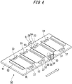
- FIG. 4 illustrates a configuration regarding magnetization processing in a state where the package blank BL is laterally conveyed in the supply line 22a.
- lateral conveyance of the package blank BL in the supply line 22a is performed in the lateral direction illustrated by a void arrow of FIG. 4 by a conveying machine 50. Therefore, in the lateral conveyance, the magnetic region 37 and the magnetic region 33 are located on respective both sides with a central portion of each package blank BL therebetween in the direction perpendicular to the conveying direction.
- a plurality of pushers 52 are arranged on a conveyor 51 that forms a conveying surface such that a plurality of package blanks BL can be laterally conveyed.
- the pushers 52 each are a rectangular parallelepiped member having a predetermined height, the longitudinal direction is along the width direction of the conveyor 51.
- a placement space where laterally conveyed each package blank BL can be disposed in a predetermined unfolded state is formed between the adjacent pushers 52.
- This predetermined unfolded state means a state where the blank portion corresponding to the front wall 31a provided with the magnetic region 33, and the blank portion corresponding to the tongue 38 provided with the magnetic region 37 are unfolded on the conveying surface so as to be capable of being magnetized by magnetizing rollers 55, 59 described below.
- the whole of the package blank BL including both the blank portions is unfolded.
- each package blank BL is thrown down to the placement space 52a from the hopper 24.
- An interval between the adjacent pushers 52 is set to be slightly larger than the lateral width of the package blank BL such that the package blank BL is smoothly housed in the placement space 52a.
- the pushers 52 each function as a regulating member that regulates movement of the package blank BL so as to house the package blank BL in the placement space 52a.
- the magnetic regions 33, 37 on the package blanks BL are located at such positions as to protrude to the outside of the placement spaces 52a from ends of the pushers 52.
- the magnetic regions 33, 37 are each oblongly formed in the lateral direction of the package blank BL, and therefore the respective longitudinal directions (oblongly extending directions) of the magnetic regions 33, 37 that protrude to the outside of the placement space 52a substantially coincide with the conveying direction of each package blank BL.
- the magnetizing rollers 55, 59 are disposed at such positions as to be able to come into contact with the protruding magnetic regions 33, 37. More specifically, a vertical wall 57 provided on the left side in the conveying direction of the conveyor 51, on which the magnetic region 33 protrudes, is mounted with a support shaft 58 so as to horizontally extend in the direction perpendicular to the conveying direction, and the magnetizing roller 59 is rotatably mounted on the support shaft 58.
- the vertical walls 53, 57 are fixed to a base portion of the supply line 22a, and therefore stays at a constant position regardless of the conveyance of the conveyor 51. Therefore, the magnetizing roller 59, 55 are disposed above the magnetic regions 33, 37 of the package blank BL laterally conveyed by the conveyor 51, respectively.
- a counter roller 56 is disposed so as to face the magnetizing roller 55 below the magnetizing roller 55, and a counter roller 60 is disposed so as to face the magnetizing roller 59 below the magnetizing roller 59.
- the counter rollers 56, 60 are rotatably supported by the support shafts (not illustrated) similarly to the magnetizing rollers 55, 59.
- the package blank BL is laterally conveyed in an interval between the magnetizing roller 55 and the counter roller 56, and an interval between the magnetizing roller 59 and the counter roller 60, so that while the magnetic region 37 and the magnetic region 33 on the package blank BL come into contact with the magnetizing rollers 55, 59, respectively, the package blank BL is conveyed to the downstream side of the magnetizing rollers 55, 59.
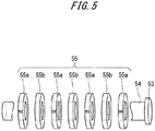
- magnetizing roller 55 a specific constitution of the magnetizing roller 55 will be described with reference to FIG. 5 .
- Magnet disks 55a formed of neodymium magnets, and iron disks 55b formed of iron which is a magnetic substance are alternately inserted into the support shaft 54, so that the magnetizing roller 55 is formed.
- the adjacent magnet disks 55a between which each iron disk 55b is sandwiched is mounted such that magnet poles in end surfaces in the axis direction of the support shaft 54 are reverse to each other.
- the thickness of each magnet disk 55a is, for example, 1 mm, and the thickness of each iron disk 55b is 0.5 mm. Additionally, the diameter of each iron disk 55b is slightly larger than the diameter of each magnet disk 55a.
- a magnetic distribution where N poles and S poles are alternately arrayed is formed on a surface of the magnetizing roller 55 (roller surface coming into contact with the magnetic material 45), and a magnetic distribution having relatively strong magnetic force is formed by correlation between the size of the magnet disks 55a and the size of the iron disks 55b, namely, correlation in the diameter and the thickness.
- the counter roller 56 facing the magnetizing roller 55 is a resin roller which is a nonmagnetic substance as described above. Therefore, the magnetic distribution formed on the surface of the magnetizing roller 55 is never disturbed due to existence of the counter roller 56.
- the magnetic region 37 efficiently comes into contact with the above surface of the magnetizing roller 55 due to the existence with the counter roller 56, and therefore the magnetic region 37 is magnetized in accordance with the magnetic distribution on the surface of the magnetizing roller 55.
- a belt-shaped magnetic distribution of the N poles and the S poles is formed along the longitudinal direction of the magnetic region 37.
- magnet disks having the same shapes as the magnet disks 55a, and iron disks having the same shapes as the iron disks 55b are alternately inserted into the support shaft 58, so that the magnetizing roller 59 is formed. That is, also in the magnetizing roller 59, correlation between the size of the magnet disks and the size of the iron disks are equal to the correlation between the size of the magnet disks 55a and the size of the iron disks 55b in the magnetizing roller 55. Consequently, also in the magnetic region 33, a belt-shaped magnetic distribution of N poles and S poles is satisfactorily formed along the longitudinal direction of the magnetic region 33.
- the magnetic regions 33, 37 are magnetized by the magnetizing rollers 55, 59 formed as described above.
- the contact state of each magnetic region and each magnetizing roller is kept, and therefore a desired magnetic distribution can be reliably formed in each of the magnetic regions.
- each package blank BL is laterally conveyed by the conveying machine 50, and therefore the magnetizing timing of the magnetic region 33 and the magnetizing timing of the magnetic region 37 are substantially the same, and the magnetizing periods are partially overlapped, magnetization of the magnetic regions can be performed as quickly as possible.
- the interval between the adjacent pushers 52 is set to be larger than the width in the lateral direction of each package blank BL such that the package blank BL is smoothly disposed from the hopper 24 in the placement space 52a on the conveyor 51.
- a predetermined clearance L0 exists between the package blank BL and each pusher 52.
- the clearance between each pusher 52 and the package blank BL is useful for smooth placement.
- the clearance is a surplus space where the package blank BL can move in the placement space 52a.
- FIG. 6(b) to FIG. 6(d) each are a sectional view taken along the conveying direction of the package blank BL disposed in the placement space 52a, similarly to FIG. 6(a) .
- an interval between the pushers 52 forming each placement space 52a is made to be the same as the width in the lateral direction of the package blank BL as much as possible.
- each chamfer 52b is suitably provided in consideration of ease of housing of the package blank BL in the placement space 52a.
- a pressing device 62, 64 that presses the package blank BL disposed in the placement space 52a toward the conveying surface may be provided in each placement space 52a.
- the pressing device 62 illustrated in FIG. 6(c) is a spring plate which is bent such that urging force acts on the package blank BL from a plate leading end 62a.
- 6(d) is a brush which causes urging force to act on the package blank BL by contact with brush bristles 64d.
- These pressing devices 62, 64 operate so as to be brought into the states illustrated in FIGS. 6(c) and 6(d) after the package blank BL is disposed in the placement space 52a from the hopper 24.
- FIG. 7 a state where the magnetization processing is performed for the package blank BL being longitudinally conveyed by a magnetizing roller 550 and a counter roller 551 is schematically illustrated as a top view at an upper stage (a) and as a side view at a lower stage (b).
- the magnetizing roller 550 has a configuration similar to the configuration of the magnetizing roller 55 illustrated in FIG. 5 .
- FIG. 7 In a form of the magnetization processing illustrated in FIG.
- the magnetizing roller 550 and the counter roller 551 are mounted on the conveying machine such that the axial direction of the magnetizing roller 550 is orthogonal to the conveying direction.
- the package blank BL is conveyed in the longitudinal direction with respect to the magnetizing roller 550 and the counter roller 551 that are thus installed, the magnetic region 33 and the magnetic region 37 are sequentially magnetized by the magnetizing roller 550.
- the deviated state is maintained.
- the tongue-lid part 32 is closed in a state of slightly deviating from or slightly inclining with respect to the package body 31, and therefore this formation is not preferable.
- FIG. 8 illustrates a placement configuration of the magnetizing rollers for magnetization processing in the longitudinal conveyance step adopted in the packaging machine of the present invention, in the light of this point.
- a top view of the placement configuration is illustrated in an upper stage (a) in FIG. 8
- a side view of this configuration is illustrated in a lower stage (b).
- the magnetizing roller 59 and the counter roller 60 corresponding to the magnetic region 33, and the magnetizing roller 55 and the counter roller 56 corresponding to the magnetic region 37 are disposed along the conveying direction.
- a magnetic distribution formed on each of surfaces of the magnetizing roller 55 and the magnetizing roller 59 is adjusted such that magnetic fields formed in a portion of the magnetic region 37 and a portion of the magnetic region 33 that face each other are different magnet poles (for example, an N pole is formed in a portion of the magnetic region 33, and an S pole is formed in a portion of the magnetic region 37, as illustrated in FIG. 8 ).
- the adjustment of the magnetic distribution is performed by adjustment of placement of magnet disks and iron disks included in each magnetizing roller.
- a protrusion 60b is provided on a peripheral surface of the counter roller 60, and a protrusion 56b is provided on a peripheral surface of the counter roller 56.
- This protrusion 60b is provided on the peripheral surface of the counter roller 60 such that the magnetic region 33 can come into contact with the magnetizing roller 59 by contact of a package portion provided with the magnetic region 33 with the protrusion 60b, and a package portion provided with no magnetic region 33 (including a package portion provided with the magnetic region 37) comes into non-contact with the magnetizing roller 59 by contact of the package portion with a peripheral portion 60a provided with no protrusion 60b, when the package blank BL is fed between the magnetizing roller 59 and the counter roller 60.
- the protrusion 56b is provided on the peripheral surface of the counter roller 56 such that the magnetic region 37 can come into contact with the magnetizing roller 55 by contact of the package portion provided with the magnetic region 37 with the protrusion 56b, and the package portion provided with no magnetic region 37 (including the package portion provided with the magnetic region 33) comes into non-contact with the magnetizing roller 55 by contact of the package portion provided with a peripheral portion 56a provided with no protrusion 56b, when the package blank BL is fed between the magnetizing roller 55 and the counter roller 56.
- the above magnetization processing is performed in the lateral conveyance process in the supply line 22a and the longitudinal conveyance process in the supply line 22b. Also in a place other than these places, the magnetization processing for the magnetic regions 33, 37 may be performed by use of the magnetizing rollers 55, 59.
- the above magnetization processing can be performed on the fifth wheel 20 where the package blank BL in contact with the inner wrapping body IB is folded. On the fifth wheel 20, the package blank BL is rotationally moved on a periphery of the wheel, but the movement is substantially the same as the lateral conveyance. Accordingly, the magnetization processing on the fifth wheel 20 can be applied to the magnetization processing which is substantially the same as the magnetization processing in the above lateral conveyance process.
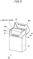
- FIG. 9 discloses a so-called hinge-lid package (hereinafter referred to simply as a "package") 40 for housing a cigarette bundle.
- a lid part 42 is hinged to a package body 41 through a hinge part 46, so that an opening of a housing space (space where a cigarette bundle is housed) can be opened and closed in the package body 41.
- the package 40 is provided with magnetic regions 44, 45 as a locking mechanism of the lid part 42 to the package body 41.
- the magnetic regions 44, 45 each are formed by being coated with a magnetic material containing a ferrite-based magnetic material. Additionally, in the completion state of the package 40 illustrated in FIG. 9 , the magnetic regions 44, 45 are magnetized, and the lid part 42 and the package body 41 are locked by magnetic attraction that acts between the both regions.
- neodymium-based magnetic materials may be utilized for magnetic regions 44, 45.
- the magnetic region 45 is formed below a cutout 43b of an inner frame front surface 43a of an inner frame 43 included in the package body 41, as an oblong region extending to the sides of the package.
- the magnetic region 44 is formed on an inner flap 42a overlapped with an inner surface of a front panel of the lid part 42, as an oblong region extending to the sides of the package, similarly to the magnetic region 45.
- the relative relation between the position of the magnetic region 45 in the inner frame front surface 43a, and the position of the magnetic region 44 in the inner flap 42a is determined such that the above positions face each other in a state where the lid part 41 closes the opening of the housing space.
- the lid part 42 when the lid part 42 is closed from the state illustrated in FIG. 9 by a user, and the magnetic region 44 comes close to the magnetic region 45 to some extent, the lid part 42 connected by a flange is attracted toward the package body 41 (inner frame 43) by magnetic attraction that acts between both the magnetic regions, and the magnetic region 44 comes into contact with the magnetic region 45, so that contact sound which indicates the contact is generated. Then, the contact state is maintained by the magnetic attraction between both the magnetic regions. Accordingly, the magnetic attraction is requested to be larger than restoring force for attempting to separate the lid part 42 from the package body 41 by the hinge connection of the hinge part 46.
- the lid part 42 When the lid part 42 is opened by the contact of the both the magnetic regions from the state where the lid part 42 closes the opening of the housing space, the user needs to make force larger than the magnetic attraction between both the magnetic regions to act on the lid part 42, and to rotate the lid part 42. Accordingly, as long as force smaller than the magnetic attraction acts on the lid part that is in a closed state, the closed state is maintained, and therefore it can be said that the magnetic attraction is resistance force for preventing the lid part 42 from opening accidentally. Accordingly, the magnetic attraction is requested to be force that is larger than necessary resistance force, and is smaller than predetermined force such that force for intentionally opening the lid part 42 by a user does not become excessive unnecessarily.
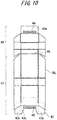
- FIG. 10 illustrates a package blank BL obtained by unfolding the package 40 illustrated in FIG. 9 .
- the package blank BL is composed of a blank portion corresponding to the package body 41 including the inner frame 43, and a blank portion corresponding to the lid part 42.
- the blank portions each are a component forming a part of the package blank BL.
- the magnetic region 44 formed on the lid part 42 is disposed on the blank portion corresponding to the inner flap 42a
- the magnetic region 45 formed on the package body 41 is disposed on the blank portion corresponding to the inner frame front surface 43a.
- the former blank portion is equivalent to a first blank portion of the present invention
- the latter blank portion is equivalent to a second blank portion of the present invention.
- the magnetic region 45 is disposed on the inner frame 43.
- the lid part 42 is connected to the package body 41, and is a separated member from the inner frame 43.
- the magnetic regions 44, 45 can be magnetized by the magnetizing rollers 55, 59 at substantially the same timing as described above with reference to FIG. 4 .
- the magnetic region 45 on the inner frame 43 and the magnetic region 44 on the lid part 42 may be magnetized by the corresponding magnetizing rollers at different timing in the respective conveyance processes. In this case, after both the regions are magnetized, the both are bonded to each other.
- FIG. 11 illustrates a reference example of magnetization processing of the magnetic regions 33, 37 (44, 45).
- each package 30 (40) that is a complete body as a package, namely that is fed out from a feed line 32 is sequentially conveyed to a magnetizing machine 70 by a conveying machine 50, and the magnetization processing is performed in the state of the package complete body.
- the magnetizing machine 70 is a machine that receives power supply from a power supply unit 71, and generates a powerful magnetic field between two electrodes. Then, each package 30 (40) conveyed by the conveying machine 50 is sent into a space between the electrodes to be stopped.
- the magnetic field is generated in this state, so that the unmagnetized magnetic regions 33, 37 (44, 45) included in the package 30 (40) are magnetized. As long as suitable magnetization is performed, a plurality of unmagnetized packages may be placed between the electrodes.
Landscapes
- Engineering & Computer Science (AREA)
- Mechanical Engineering (AREA)
- Power Engineering (AREA)
- Physics & Mathematics (AREA)
- Electromagnetism (AREA)
- Making Paper Articles (AREA)
- Wrapping Of Specific Fragile Articles (AREA)
- Auxiliary Devices For And Details Of Packaging Control (AREA)
- Cartons (AREA)
Abstract
Description
- The present invention relates to a packaging machine for a package having a package body, and a lid part for a housing space of the package body, and a packaging method therefor.
- Recently, as a package for a cigarette, a large number of lid packages are adopted. In the lid package, a lid part is hinged to a body side of the lid package, so that a filter cigarette in the inside on the body side can be satisfactorily protected from the outside. Additionally, with the lid part closed, dust in the package is inhibited from falling outside. Therefore, the lid package preferably includes a locking mechanism for the lid part in order to prevent the lid part from opening accidentally. For example, the locking mechanism is implemented by utilizing engagement of a tongue piece formed by being cut and raising from an inner frame of the package, and an edge formed in an inner flap of the lid part. In this case, the lid part needs to be opened by force for disengaging the tongue piece from the edge in order to open the lid part, and therefore accidental opening of the lid part is prevented.
- Herein, a packaging machine that manufactures a lid package having such a locking mechanism which controls opening and closing a lid part is disclosed in, for example, Patent document 1. In the packaging machine, in order to manufacture a tongue piece which is a part of the locking mechanism, a function of forming a tongue piece forming part is added to a notch which forms a blank from a web, while a folding protrusion and a folding hole for folding the tongue piece forming part are provided in a folding tacker and a tacker receiver used for folding of the blank.
- In a lid package disclosed in
Patent document 2, magnet members are utilized for a locking mechanism for a lid part and a body side. More specifically, the lid part is locked to the body side by magnetic attraction of a magnetic material on an inner flap, and a magnetic material on a lid part side, to such an extent that accidental opening of the lid part is prevented.Patent document 2 mentions that these magnet members are magnetized during manufacturing of the package. -
- [Patent document 1]
Japanese Patent Laid-Open No. 2000-43166 - [Patent document 2] International Publication No.
2014/096427 - [Patent document 3]
Japanese Patent Laid-Open No. 5-270528 - [Patent document 4]
Japanese Patent No. 4777707 - In the prior arts, in a case where attraction of the magnetic materials is utilized as the locking mechanism of the lid part of the lid package, how the magnetic materials are magnetized at which timing is not specifically studied. The magnetization of the magnetic materials needs to be performed such that suitable locking between the lid part and the package body is formed, namely, suitable relative positional relation is formed so as to bring the lid part into contact with the package body without deviating the relative position of the lid part and the package body. However, in the prior arts, a magnetization aspect of the magnetic materials is not specifically disclosed.
- Particularly, in a case where a large number of lid packages are manufactured by a packaging machine, time necessary for magnetizing magnetic materials needs to be reduced as short as possible in order to enhance manufacturing efficiency. However, when the time necessary for the magnetization is reduced, it becomes difficult to form desired magnetic distributions in the magnetic materials, and it becomes difficult to obtain a locking state of the suitable relative positional relation between the lid part and the package body.
- The present invention has been made in view of the above problems, and an object of the present invention is to provide a packaging machine that forms desired magnetic distributions in magnetic materials as quickly as possible in a manufacturing step of a lid package having a locking mechanism between a lid part and a package body by utilizing the magnetic materials in the packaging machine.
- In order to solve the above problems, a packaging machine of the present invention adopts a configuration in which respective magnetic regions each coated with a magnetic material containing a magnetic material are formed on a lid part and a package body side, and magnetizing rollers that magnetize the magnetic materials while coming into contact therewith are utilized. The magnetizing rollers magnetize the magnetic materials by coming into contact with the magnetic regions, and therefore each magnetic region can be magnetized while the package blank is conveyed, and it is possible to quickly and stably form a magnetic distribution in each magnetic region.
- More specifically, the present invention is a packaging machine for a package, the package having a package body having a housing space for housing an object to be housed, and a lid part formed so as to cover an opening of the housing space of the package body, wherein the lid part is provided with a lid-side magnetic region that is coated with an unmagnetized magnetic material, and the package body is provided with a body-side magnetic region that is coated with an unmagnetized magnetic material, at such a predetermined position on the package body as to face the lid-side magnetic region in a complete state of the package where the lid part covers the opening of the housing space. Additionally, the packaging machine includes: a conveying machine that conveys a package blank for the package, while in the package blank, at least a first blank portion related to the lid-side magnetic region, and a second blank portion related to the body-side magnetic region are in a predetermined unfolded state; a lid-side magnetizing roller that is supported so as to be able to come into contact with the lid-side magnetic region of the package blank being conveyed in the predetermined unfolded state by the conveying machine, and so as to be rotatable when coming into contact, and has a permanent magnet which magnetizes the magnetic material of the lid-side magnetic region; and a body-side magnetizing roller that is supported so as to be able to come into contact with the body-side magnetic region of the package blank being conveyed in the predetermined unfolded state by the conveying machine, and so as to be rotatable when coming into contact, and has a permanent magnet for magnetizing the magnetic material of the body-side magnetic region so as to form a predetermined magnetic distribution corresponding to a magnetic distribution in the lid-side magnetic region formed by the lid-side magnetizing roller.
- In the packaging machine according to the present invention, the package having the package body and the lid part is manufactured from the package blank. Herein, the package blank includes the lid-side magnetic region that is a magnetic region on the lid part side, and the body-side magnetic region that is a magnetic region on the package body. Placement on the package blank is determined such that both the magnetic regions face each other in a completed state as a package after magnetization. Herein, as both the magnetic materials included in the magnetic regions, for example, a coating material containing a ferrite-based magnetic material or a neodymium-based magnetic material can be adopted. Both the magnetic regions only need to be not yet magnetized (unmagnetized state) at a point of time before magnetization processing described below. As to magnetic region forming time, the magnetic regions may be already coated on the package blank before the package is manufactured by the packaging machine, or the magnetic regions may be coated in a stage before the magnetization processing which is a process of package manufacturing by the packaging machine.
- The magnetization of the lid-side magnetic region and the body-side magnetic region formed on the package blank is implemented by actions of the lid-side magnetizing roller and the body-side magnetizing roller corresponding to the respective magnetic regions on conveyance of the package blank in the predetermined unfolded state by the conveying machine. More specifically, the conveying machine conveys the package blank in the predetermined unfolded state. This predetermined unfolded state is such a state where the first blank portion related to the lid-side magnetic region, and the second blank portion related to the body-side magnetic region are unfolded such that the lid-side magnetizing roller and the body-side magnetizing roller can come into contact with the respective magnetic regions. Accordingly, a blank portion other than the first blank portion and the second blank portion in the package blank may be folded to some extent in order to manufacture the package as long as each magnetic region can be magnetized, or may be unfolded like the first blank portion and the like.
- As the conveyance form by the conveying machine, various forms can be adopted, as long as magnetization of the respective magnetic regions by the lid-side magnetizing roller and the body-side magnetizing roller, described below, is possible. For example, a conveying machine that conveys the package blank on a straight line may be adopted, or a drum-type conveying machine that conveys the package blank along a predetermined circumference may be adopted.
- Both the rollers are disposed with respect to the package blank being conveyed in the predetermined unfolded state by the conveying machine such that the lid-side magnetizing roller comes into contact with the lid-side magnetic region on the first blank portion, and the body-side magnetizing roller comes into contact with the body-side magnetic region on the second blank portion. The permanent magnets are rotatably supported on the support shafts. Therefore, when the respective magnetizing rollers come into contact with the corresponding magnetic regions on the package blank being conveyed, the permanent magnets rotate, so that the package blank is conveyed downstream while the contact states between the permanent magnets and the respective magnetic regions are maintained. Therefore, the respective magnetic regions are magnetized without preventing conveyance of the package blank, and the contact states between the magnetic regions and the respective magnetizing rollers are maintained. Accordingly, it is possible to stably form a desired magnetic distribution in each magnetic region.
- In each of the magnetized lid-side magnetic region and the magnetize body-side magnetic region, a predetermined magnetic distribution in which the magnetic distribution in the body-side magnetic region corresponds to the magnetic distribution in the lid-side magnetic region is formed such that both the magnetic regions are locked to each other by magnetic attraction. That is, the magnetic distributions in the both the magnetic regions are formed such that suitable locking by magnetic attraction between magnetic N poles and S poles is possible. For example, the S pole is formed in a portion of the lid-side magnetic region which faces a portion, where the N pole is formed in the body-side magnetic region, in the completed state of the package. From a broad view, the N pole portions and the S pole portions in the respective magnetic regions are disposed corresponding to each other such that the locking state of the lid part and the package body becomes a suitable locking state with no deviation.
- Herein, in the above packaging machine, contact with the lid-side magnetic region by the lid-side magnetizing roller, and contact with the body-side magnetic region by the body-side magnetizing roller may be performed in at least a partially overlapped period. Additionally, as another method, contact with the lid-side magnetic region by the lid-side magnetizing roller, and contact with the body-side magnetic region by the body-side magnetizing roller may be performed in different periods which are not overlapped. In either contact form, the lid-side magnetizing roller and the body-side magnetizing roller perform magnetization processing by coming into contact with the lid-side magnetic region and the body-side magnetic region, respectively, and therefore it is possible to stably form the magnetic distribution in each magnetic region.
- Herein, in the above packaging machine, the lid-side magnetizing roller may be formed by alternately supporting a plurality of lid-side magnet disks each formed of the permanent magnet, and a plurality of lid-side magnetic substance disks each formed of a magnetic substance on a support shaft rotatably, the body-side magnetizing roller may be formed by alternately supporting a plurality of body-side magnet disks each having the same width as each of the lid-side magnet plates and each formed of the permanent magnet, and a plurality of body-side magnetic substance disks each having the same width as each of the lid-side magnetic substance disks and each formed of a magnetic substance on a support shaft rotatably. In this case, a belt-shaped magnetic distribution is formed in the lid-side magnetic region by the lid-side magnetizing roller, and the predetermined magnetic distribution may be formed in a belt shape in the body-side magnetic region by the body-side magnetizing roller.
- Thus, the lid-side magnetizing roller and the body-side magnetizing roller are each formed by alternately disposing the magnet disks and the magnetic substance disks, so that the respective corresponding belt-shaped magnetic distributions can be formed in the lid-side magnetic region and the body-side magnetic region. That is, the width of the belt-shaped magnetic distribution in each magnetic region is formed by contact of side surfaces of the corresponding magnet disk and magnetic substance disk and each magnetic region. Thus, the belt-shaped magnetic region is formed, such that it is possible to improve magnetic attraction that acts between the lid-side magnetic region and the body-side magnetic region.
- Furthermore, a diameter of each of the lid-side magnetic substance disks may be not less than a diameter of each of the lid-side magnet disks, and a diameter of each of the body-side magnetic substance disks may be not less than a diameter of each of the body-side magnet disks. Thanks to diligent efforts of the inventor of this application, it is found that magnetic distribution formation in the corresponding magnetic regions can be suitably performed by making the respective diameters of the lid-side and body-side magnetic substance disks to be equal to or larger than the diameters of the corresponding magnet disks. In a case where the diameter of each magnetic substance disk is made larger than the diameter of each magnet disk, the different amount of the diameters only need to be suitably determined by considering magnetic force and the like in the magnetic distributions formed in the magnetic regions.
- The packaging machine described above further includes: a lid-side counter roller that is formed of a nonmagnetic substance, is located on a side opposite to the lid-side magnetizing roller with the package blank sandwiched between the lid-side counter roller and the lid-side magnetizing roller when the lid-side magnetizing roller comes into contact with the package blank, and is similarly supported so as to be able to come into contact with the package blank, and so as to be rotatable when coming into contact; and a body-side counter roller that is formed of a nonmagnetic substance, is located on a side opposite to the body-side magnetizing roller with the package blank sandwiched between the body-side counter roller and the body-side magnetizing roller when the body-side magnetizing roller comes into contact with the package blank, and is similarly supported so as to be able to come into contact with the package blank, and so as to be rotatable when coming into contact.
- As described above, the lid-side counter roller is disposed so as to be paired with the lid-side magnetizing roller, and the body-side counter roller is disposed so as to be paired with the body-side magnetizing roller, so that in magnetization in each magnetic region, the corresponding magnetic region is sandwiched between each magnetizing roller and each counter roller, and a contact property between each magnetizing roller and each magnetic region can be made more satisfactory. As a result, it is possible to more suitably form the desired magnetic distributions in the lid-side magnetic region and the body-side magnetic region.
- Herein, the lid-side counter roller and the body-side counter roller are each formed of a nonmagnetic substance material. As a result, only a magnetic field formed by the corresponding magnetizing roller acts in the magnetization in each magnetic region. The lid-side magnetic region and the body-side magnetic region are formed by being coated with respective magnetic materials, and therefore the thickness of each region is relatively thin. The inventor of this application finds that in a case where such a relatively thin magnetic material is magnetized, when a magnetic field that reaches the counter roller from the magnetizing roller is utilized, the magnetic material is not suitably magnetized, and on the other hand, when the counter roller is the nonmagnetic substance, and only a magnetic field formed by the magnetizing roller acts on the magnetic material, the magnetic material is effectively magnetized. Accordingly, formation of the counter roller side formed of the nonmagnetic substance material suitably contributes to solution of the problems of the present invention. As the nonmagnetic substance material that forms each of the counter rollers, a resin material can be exemplified.
- Herein, in the above packaging machine that includes the lid-side counter roller and the body-side counter roller, the conveyance state of the package blank includes two conveyance forms. First, in a first conveyance aspect, the predetermined unfolded state is a state where the first blank portion and the second blank portion are located on opposite sides in a direction perpendicular to a conveying direction of the package blank with a central portion of the package blank therebetween. This conveyance aspect is referred to as lateral conveyance.
- In a case where the package blank is laterally conveyed by the conveying machine, the conveying machine may have a regulating member of a predetermined height, the regulating member being a member which forms a placement space for disposing the package blank in the predetermined unfolded state and regulate movement of the package blank at front and rear in the conveying direction of the package blank, and the regulating member may be disposed so as to come into contact with the package blank from the front and the rear in the conveying direction, and a chamfer may be formed on an upper edge of the regulating member on a side close to the placement space.
- In a case of the lateral conveyance, when the lid part side and the package body side that are in a sandwiching state of the package blank for magnetization processing deviate from each other, frictional force by sandwiching acts on one side of the package blank being conveyed, and therefore there is a fear that the package blank is rotated on the conveying surface by this frictional force. However, as described above, the regulating material is disposed so as to come into contact with the package blank at the front and the rear in the conveying direction, so that even if force for rotating the package blank acts, positional deviation of the package blank can be suppressed by the state of contact with the package blank of the regulating material. However, when the regulating material is disposed so as to come into contact with the package blank, it is not easy to dispose the package blank in the placement space formed by the regulating material. Therefore, the chamfer is formed on the upper edge of the regulating material on the side close to the placement space, so that the package blank can be lowered from above with respect to the placement space and easily disposed at the position by a guide effect by the chamfer.
- In the case where the package blank is laterally conveyed by the conveying machine as described above, as another method, the conveying machine may have a regulating member of a predetermined height, the regulating member being a member which forms a placement space for disposing the package blank in the predetermined unfolded state and regulate movement of the package blank at front and rear in the conveying direction of the package blank, and a pressing device that presses the package blank disposed in the placement space against a conveying surface from above. The package blank is pressed in the placement space by such a pressing device, so that even if the force for rotating the package blank acts, it is possible to suppress the positional deviation of the package blank.
- As a second conveyance aspect, the predetermined unfolded state is a state where the first blank portion and the second blank portion are located along a conveying direction of the package blank. This conveyance aspect is referred to a longitudinal conveyance. In a case where this longitudinal conveyance is performed, the lid-side counter roller and the body-side counter roller are disposed such that one of the lid-side counter roller and the body-side counter roller is located on an upstream side with respect to the other counter roller along a conveying direction of the package, the lid-side counter roller has, on a roller periphery, a first protrusion enabling the first blank portion to be sandwiched between the lid-side magnetizing roller and the first protrusion in a period in which the lid-side magnetizing roller is in contact with the lid-side magnetic region, and the lid-side counter roller is formed such that the lid-side magnetizing roller is in non-contact with the package blank in a case where the lid-side counter roller is in contact with the package blank at a portion on the periphery other than the first protrusion, the body-side counter roller has, on a roller periphery, a second protrusion enabling the second blank portion to be sandwiched between the body-side magnetizing roller and the second protrusion in a period in which the body-side magnetizing roller is in contact with the body-side magnetic region, and the body-side counter roller is formed such that the body-side magnetizing roller is in non-contact with the package blank in a case where the body-side counter roller is in contact with the package blank at a portion on the periphery other than the second protrusion. Additionally, the first protrusion and the second protrusion are disposed in the lid-side counter roller and the body-side counter roller respectively such that the lid-side magnetic region comes into contact with the lid-side magnetizing roller, and does not come into contact with the body-side magnetizing roller, and the first protrusion and the second protrusion are further disposed in the lid-side counter roller and the body-side counter roller respectively such that the body-side magnetic region comes into contact with the body-side magnetizing roller, and does not come into contact with the lid-side magnetizing roller.
- In a case where the package blank is longitudinally conveyed by the conveying machine, the first blank portion and the second blank portion are located to be lined along the conveying direction of the package blank. Therefore, there is a possibility that the one magnetic region is magnetized in an overlapped manner by the two magnetizing rollers depending on the placement relation between the lid-side magnetizing roller and the body-side magnetizing roller. When the one magnetic region is magnetized in the overlapped manner, the magnetic distribution formed therein becomes a disordered distribution, that is, becomes a distribution which is not the desired magnetic distribution, which is unpreferable.
- Therefore, as described above, the first protrusion is provided on the periphery of the lid-side counter roller, and the second protrusion is provided on the periphery of the body-side counter roller. Consequently, in a state where the first blank portion is sandwiched between the lid-side magnetizing roller and the lid-side counter roller (first protrusion) due to existence of the first protrusion, the lid-side magnetizing roller comes into contact with the lid-side magnetic region on the first part, and the sandwiching state is eliminated by rotation of the lid-side counter roller, the contact of the lid-side magnetizing roller with lid-side magnetic region is also eliminated. Similarly, in a state where the second blank portion is sandwiched between the body-side magnetizing roller and the body-side counter roller (second protrusion) due to existence of the second protrusion, the body-side magnetizing roller comes into contact with the body-side magnetic region on the second part, and the sandwiching state is eliminated by rotation of the body-side counter roller, the contact of the body-side magnetizing roller with body-side magnetic region is also eliminated. Accordingly, with such a configuration, even in a case where the longitudinal conveyance is performed, only the lid-side magnetizing roller comes into contact with the lid-side magnetic region, and only the body-side magnetizing roller comes into contact with the body-side magnetic region, so that it is possible to avoid the above state where the one magnetic region is magnetized in the overlapped manner.
- Additionally, the present invention can be grasped from an aspect of a packaging method for a package. In this case, the present invention is a packaging method for a package, the package having a package body having a housing space for housing an object to be housed, and a lid part formed so as to cover an opening of the housing space of the package body, wherein the lid part is provided with a lid-side magnetic region that is coated with an unmagnetized magnetic material, the package body is provided with a body-side magnetic region that is coated with an unmagnetized magnetic material, at such a predetermined position on the package body as to face the lid-side magnetic region in a complete state of the package where the lid part covers the opening of the housing space. The packaging method includes: a conveying step of conveying a package blank for the package, while in the package blank, at least a first blank portion related to the lid-side magnetic region, and a second blank portion related to the body-side magnetic region are in a predetermined unfolded state, a lid-side magnetizing step of bringing a lid-side magnetizing roller having a permanent magnet and rotatably supported into contact with the lid-side magnetic region of the package blank being conveyed in the predetermined unfolded state, and magnetizing the magnetic material of the lid-side magnetic region; and a body-side magnetizing step of bringing a body-side magnetizing roller having a permanent magnet and rotatably supported into contact with the body-side magnetic region of the package blank being conveyed in the predetermined unfolded state, and magnetizing the magnetic material of the body-side magnetic region so as to form a predetermined magnetic distribution corresponding to a magnetic distribution in the lid-side magnetic region formed by the lid-side magnetizing roller. According to this packaging method, it is possible to stably form a magnetic distribution in each magnetic region, similarly to the case of the above packaging machine.
- In the above packaging method for a package, contact with the lid-side magnetic region by the lid-side magnetizing roller in the lid-side magnetizing step, and contact with the body-side magnetic region by the body-side magnetizing roller in the body-side magnetizing step may be performed in at least a partially overlapped period. As another method, contact with the lid-side magnetic region by the lid-side magnetizing roller in the lid-side magnetizing step, and contact with the body-side magnetic region by the body-side magnetizing roller in the body-side magnetizing step may be performed in different periods which may be not overlapped.
- Furthermore, in the above packaging method for a package, in the conveying step, the package blank may be conveyed such that the first blank portion and the second blank portion are located along a conveying direction of the package blank, and the magnetization of the magnetic material of the lid-side magnetic region in the lid-side magnetizing step, and the magnetization of the magnetic material of the body-side magnetic region in the body-side magnetizing step may be sequentially performed in accordance with conveyance of the package blank such that in a state where the lid-side magnetic region and the body-side magnetic region face each other at a time of formation of the package, magnetic fields formed in one portion of the lid-side magnetic region and one portion of the body-side magnetic region that face each other may be different from each other. In the present invention, which magnetization is first performed is not limited. In addition, as long as technical discrepancy is not caused, the technical ideas disclosed in the above packaging machine can be applied to the packaging method for a package of the present invention.
- According to the present invention, it is possible to provide a packaging machine that forms a desired magnetic distribution in a magnetic material as quickly as possible in a manufacturing process of a lid package having a locking mechanism between a lid part and a package body by utilizing the magnetic material in the packaging machine.
-
- [
FIG.1] FIG. 1 is a diagram schematically illustrating a tongue-lid package manufactured by a packaging machine of the present invention. - [
FIG.2] FIG. 2 is a diagram illustrating a package blank obtained by unfolding the tongue-lid package illustrated inFIG. 1 . - [
FIG.3] FIG. 3 is a diagram illustrating a schematic configuration of the packaging machine of the present invention. - [
FIG.4] FIG. 4 is a diagram illustrating a configuration for magnetizing magnetic regions formed in the package blank, included in the packaging machine of the present invention. - [
FIG.5] FIG. 5 is a diagram illustrating a schematic configuration of a magnetizing roller included in the magnetizing configuration illustrated inFIG. 4 . - [
FIG.6] FIG. 6 is a diagram illustrating a placement state of the package blank in a case where the package blank is laterally conveyed by a conveying machine, in the packaging machine of the present invention. - [
FIG.7] FIG. 7 is a diagram for illustrating a state where the magnetic regions are magnetized in an overlapped state in a case where the package blank is longitudinally conveyed by the conveying machine. - [
FIG.8] FIG. 8 is a diagram for illustrating a state where the magnetic regions are magnetized, in a case where the package blank is longitudinally conveyed by the conveying machine, in the packaging machine of the present invention. - [
FIG.9] FIG. 9 is a diagram schematically illustrating a hinge-lid package manufactured by the packaging machine of the present invention. - [
FIG.10] FIG. 10 is a diagram illustrating a package blank obtained by unfolding the hinge-lid package illustrated inFIG. 9 . - [
FIG.11] FIG. 11 is a diagram illustrating another embodiment (reference example) for magnetizing the lid package. - Hereinafter, a specific embodiment of the present invention will be described with reference to the drawings. The size, materials, shapes, and relative placement and the like of components described in the embodiment are not intended to limit the scope of the invention thereto, unless otherwise stated.
-
FIG. 1 discloses a so-called tongue-lid package (hereinafter referred to simply as a "package") 30 for housing a cigarette bundle, thepackage 30 illustrated inFIG. 1 is in a closed state where a housing space (space where the cigarette bundle is housed) inside the package is closed.FIG. 2 illustrates a package blank BL obtained by unfolding thepackage 30. In thepackage 30, a tongue-lid part 32 is hinged to apackage body 31, so that opening of the housing space inside thepackage body 31 can be opened and closed. In thepackage body 31, afront wall 31a located at a front surface of the package,side walls 31b located at side surfaces, abottom wall 31c located at a bottom surface, and the like form the housing space. The tongue-lid part 32 has alid 35 which is hinged to thepackage body 31, and atongue 38 which is hinged to thelid 35. In the closed state illustrated inFIG. 1 , thelid 35 is located so as to face thebottom wall 31c of thepackage body 31, and thetongue 38 is located on thefront wall 31a of thepackage body 31. - The
package 30 is provided withmagnetic regions package body 31. Themagnetic regions package 30 illustrated inFIG. 1 , themagnetic regions tongue 38 and thepackage body 31 are locked by magnetic attraction that acts between the both regions. For themagnetic regions - More specifically, the
magnetic region 33 is formed below a cutout (not illustrated) of thefront wall 31a included in thepackage body 31, as an oblong region extending to the sides of the package. On the other hand, themagnetic region 37 is formed near a leading end of thetongue 38 as an oblong region extending to the sides of the package, similarly to themagnetic region 33. The relative relation between the position of themagnetic region 33 in thepackage body 31, and the position of themagnetic region 37 in thetongue 38 is determined such that the above positions face each other in the above closed state. - In the
package 30 thus formed, when the tongue-lid part 32 is closed from the state illustrated inFIG. 1 by a user, and themagnetic region 37 comes close to themagnetic region 33 to some extent, thetongue 38 connected by a flange is attracted toward thepackage body 31 by magnetic attraction that acts between both the magnetic regions, and themagnetic region 37 comes into contact with themagnetic region 33, so that contact sound which indicates the contact is generated. Then, the contact state is maintained by the magnetic attraction between both the magnetic regions. - When the tongue-
lid part 32 is opened from the state where the tongue-lid part 32 closes the opening of the housing space by the contact of the both the magnetic regions, the user needs to make force larger than the magnetic attraction between both the magnetic regions to act on the tongue-lid part 32, and to rotate the tongue-lid part 32. Accordingly, as long as force smaller than the magnetic attraction acts on the tongue-lid part 32 which is in the closed state, the closed state is maintained, and therefore it can be said that the magnetic attraction is resistance force for preventing the tongue-lid part 32 from opening accidentally. Accordingly, the magnetic attraction is requested to be force that is larger than necessary resistance force, and is smaller than predetermined force such that force for intentionally opening the tongue-lid part 32 by a user does not become excessive unnecessarily. - As illustrated in
FIG. 2 , the package blank BL is composed of a blank portion corresponding to thepackage body 31, and a blank portion corresponding to the tongue-lid part 32. The blank portions each are a component forming a part of the package blank BL. Furthermore, themagnetic region 37 formed on the tongue-lid part 32 side is disposed on the blank portion corresponding to thetongue 38, and themagnetic region 33 formed on thepackage body 31 side is disposed on the blank portion corresponding to thefront wall 31a. The former blank portion is equivalent to a first blank portion of the present invention, and the latter blank portion is equivalent to a second blank portion of the present invention. In this specification, as to the direction of the package blank BL, the up-and-down direction ofFIG. 2 , namely, the direction from one of the magnetic regions to the other magnetic region is defined as the longitudinal direction, and the right-and-left direction ofFIG. 2 , namely, the direction perpendicular to the longitudinal direction on a surface where the package blank BL is unfolded is defined as the lateral direction. - As can be seen from
FIG. 2 , any specific blank portion is not disposed on the lateral sides of the blank portion corresponding to thetongue 38 in the package blank BL. On the other hand, blank portions corresponding to theside walls 31b of thepackage body 31 are disposed on the lateral sides of the blank portion corresponding to thefront wall 31a. Formation of a folding line itself in the package blank BL for assembling thepackage 30 is publicly known, and therefore description thereof will be omitted. - Now, a packaging machine that manufactures the
package 30 will be described with reference toFIG. 3 . The packaging machine illustrated inFIG. 3 includes ahopper 2 for cigarettes, and is provided with acigarette filling mechanism 6 that stacks twenty cigarettes from thehopper 2 in three stages in a vertically zigzag manner to fill the stacked cigarettes into each pocket 4 is provided on the lower side of thehopper 2. A cigarette bundle is transferred on a transfer line to a verticalfirst wheel 8 illustrated by a dashed line. Thefirst wheel 8 receives a bundle of the twenty cigarettes from each pocket 4 while rotating, and each cigarette bundle is pressed into abucket 12 of a verticalsecond wheel 10 illustrated by a dashed line from thefirst wheel 8, along with an aluminum foil sheet S as an inner capsule material. At this time, the aluminum foil sheet S is longitudinally folded along the periphery of the cigarette bundle. - The aluminum foil sheet S is obtained by being cut an aluminum foil web AW fed from an aluminum foil roller AR every predetermined length, and is sequentially supplied between the
first wheel 8 and thesecond wheel 10. A similar aluminum foil roller (not illustrated) is disposed in the vicinity of the aluminum foil roller AR, and this aluminum foil roller is a standby roller. Thereafter, with the rotation of thesecond wheel 10, corners and side flaps of the aluminum foil sheet S that is longitudinally folded along the cigarette bundle in the bucket are sequentially folded, so that an inner wrapping body of the cigarette bundle is formed. - A horizontal
third wheel 16 is adjacent to thesecond wheel 10 on the opposite side of thefirst wheel 8. Thethird wheel 16 sequentially receives the inner wrapping body of the cigarette bundle in the bucket from thesecond wheel 10, and transfers the inner wrapping body with the rotation. Furthermore, a horizontalfourth wheel 18 is similarly disposed adjacent to thethird wheel 16 on the opposite side of thesecond wheel 10. Thefourth wheel 18 is located on the lower side of thethird wheel 16, and receives the inner wrapping body IB from thethird wheel 16. - Then, the
fourth wheel 18 receives supply of the package blank BL illustrated inFIG. 2 from ablank supply system 22, and this package blank BL is bonded to an upper surface of the inner wrapping body IB. As illustrated inFIG. 3 , theblank supply system 22 has two supply lines, namely, asupply line 22a and asupply line 22b that connect ahopper 24 and thefourth wheel 18. In thesupply line 22a, lateral conveyance in which the package blank BL is conveyed in the lateral direction is performed. On the other hand, in thesupply line 22b, longitudinal conveyance in which the package blank BL is conveyed in the longitudinal direction is performed. The package blank BL taken out one by one from thehopper 24 is sequentially conveyed on thesupply lines fourth wheel 18. Herein, each package blank BL is already coated with the magnetic materials, is dried, and is provided with themagnetic regions hopper 24, each magnetic region is not yet magnetized. - Then, a vertical
fifth wheel 20 is disposed directly above a supply position of the package blank BL as viewed in the periphery direction of thefourth wheel 18, and thefifth wheel 20 receives the inner wrapping body IB with the package blank BL bonded thereto in the bucket. Thereafter, with the rotation of thefifth wheel 20, the package blank BL is sequentially folded, so that thepackage 30 is manufactured. Thereafter, thepackage 30 is transferred onto a similarly horizontalseventh wheel 28 through a horizontalsixth wheel 26 adjacent to thefifth wheel 20. In the process of the transfer of thepackage 30 with the rotation of theseventh wheel 28, a gluing portion of thepackage 30 is dried, and thereafter is fed to a feed line through a verticaleighth wheel 29. The feed line sequentially supplies thepackage 30 to an external packaging machine (not illustrated), and thepackage 30 is further packaged by a film sheet by this external packaging machine. - Herein, in the packaging machine illustrated in
FIG. 3 , in a conveyance process of the package blank BL, magnetization processing of themagnetic regions hopper 24, themagnetic regions magnetic regions hopper 24, the package blanks BL adjacent to each other are attracted by magnetic attraction of magnetic materials, and handling of the package blanks BL becomes difficult. More specifically, in either thesupply line 22a or thesupply line 22b forming theblank supply system 22, the magnetization processing of themagnetic regions - First, magnetization processing in the
supply line 22a will be described with reference toFIG. 4. FIG. 4 illustrates a configuration regarding magnetization processing in a state where the package blank BL is laterally conveyed in thesupply line 22a. As described above, lateral conveyance of the package blank BL in thesupply line 22a is performed in the lateral direction illustrated by a void arrow ofFIG. 4 by a conveyingmachine 50. Therefore, in the lateral conveyance, themagnetic region 37 and themagnetic region 33 are located on respective both sides with a central portion of each package blank BL therebetween in the direction perpendicular to the conveying direction. - Herein, in the conveying
machine 50, a plurality ofpushers 52 are arranged on aconveyor 51 that forms a conveying surface such that a plurality of package blanks BL can be laterally conveyed. Thepushers 52 each are a rectangular parallelepiped member having a predetermined height, the longitudinal direction is along the width direction of theconveyor 51. A placement space where laterally conveyed each package blank BL can be disposed in a predetermined unfolded state is formed between theadjacent pushers 52. This predetermined unfolded state means a state where the blank portion corresponding to thefront wall 31a provided with themagnetic region 33, and the blank portion corresponding to thetongue 38 provided with themagnetic region 37 are unfolded on the conveying surface so as to be capable of being magnetized by magnetizingrollers FIG. 4 , the whole of the package blank BL including both the blank portions is unfolded. - In placement of the package blank BL into a
placement section 52a (also refer toFIG. 6 ) on theconveyor 51, each package blank BL is thrown down to theplacement space 52a from thehopper 24. An interval between theadjacent pushers 52 is set to be slightly larger than the lateral width of the package blank BL such that the package blank BL is smoothly housed in theplacement space 52a. Thepushers 52 each function as a regulating member that regulates movement of the package blank BL so as to house the package blank BL in theplacement space 52a. - Herein, when the package blanks BL are disposed in the
placement spaces 52a fixed by thepushers 52, themagnetic regions placement spaces 52a from ends of thepushers 52. As illustrated inFIG. 2 , themagnetic regions magnetic regions placement space 52a substantially coincide with the conveying direction of each package blank BL. - On the both lateral sides in the conveying direction of the
conveyor 51, the magnetizingrollers magnetic regions vertical wall 57 provided on the left side in the conveying direction of theconveyor 51, on which themagnetic region 33 protrudes, is mounted with a support shaft 58 so as to horizontally extend in the direction perpendicular to the conveying direction, and the magnetizingroller 59 is rotatably mounted on the support shaft 58. Furthermore, avertical wall 53 provided on the right side in the conveying direction of theconveyor 51, on which themagnetic region 37 protrudes, is mounted with asupport shaft 54 so as to horizontally extend in the direction perpendicular to the conveying direction, and the magnetizingroller 55 is rotatably mounted on thesupport shaft 54. Thevertical walls supply line 22a, and therefore stays at a constant position regardless of the conveyance of theconveyor 51. Therefore, the magnetizingroller magnetic regions conveyor 51, respectively. - A
counter roller 56 is disposed so as to face the magnetizingroller 55 below the magnetizingroller 55, and acounter roller 60 is disposed so as to face the magnetizingroller 59 below the magnetizingroller 59. Thecounter rollers rollers roller 55 and thecounter roller 56, and an interval between the magnetizingroller 59 and thecounter roller 60, so that while themagnetic region 37 and themagnetic region 33 on the package blank BL come into contact with the magnetizingrollers rollers - Herein, a specific constitution of the magnetizing
roller 55 will be described with reference toFIG. 5 .Magnet disks 55a formed of neodymium magnets, andiron disks 55b formed of iron which is a magnetic substance are alternately inserted into thesupport shaft 54, so that the magnetizingroller 55 is formed. At this time, theadjacent magnet disks 55a between which eachiron disk 55b is sandwiched is mounted such that magnet poles in end surfaces in the axis direction of thesupport shaft 54 are reverse to each other. The thickness of eachmagnet disk 55a is, for example, 1 mm, and the thickness of eachiron disk 55b is 0.5 mm. Additionally, the diameter of eachiron disk 55b is slightly larger than the diameter of eachmagnet disk 55a. In the magnetizingroller 55 thus formed, a magnetic distribution where N poles and S poles are alternately arrayed is formed on a surface of the magnetizing roller 55 (roller surface coming into contact with the magnetic material 45), and a magnetic distribution having relatively strong magnetic force is formed by correlation between the size of themagnet disks 55a and the size of theiron disks 55b, namely, correlation in the diameter and the thickness. - The
counter roller 56 facing the magnetizingroller 55 is a resin roller which is a nonmagnetic substance as described above. Therefore, the magnetic distribution formed on the surface of the magnetizingroller 55 is never disturbed due to existence of thecounter roller 56. When the package blank BL is sent into the interval between the magnetizingroller 55 and thecounter roller 56 by lateral conveyance, themagnetic region 37 efficiently comes into contact with the above surface of the magnetizingroller 55 due to the existence with thecounter roller 56, and therefore themagnetic region 37 is magnetized in accordance with the magnetic distribution on the surface of the magnetizingroller 55. More specifically, in the light of a state where the longitudinal direction of themagnetic region 37 and the conveying direction of the package blank BL substantially coincide with each other, a belt-shaped magnetic distribution of the N poles and the S poles is formed along the longitudinal direction of themagnetic region 37. - Similarly to the magnetizing
roller 55, as illustrated inFIG. 5 , magnet disks having the same shapes as themagnet disks 55a, and iron disks having the same shapes as theiron disks 55b are alternately inserted into the support shaft 58, so that the magnetizingroller 59 is formed. That is, also in the magnetizingroller 59, correlation between the size of the magnet disks and the size of the iron disks are equal to the correlation between the size of themagnet disks 55a and the size of theiron disks 55b in the magnetizingroller 55. Consequently, also in themagnetic region 33, a belt-shaped magnetic distribution of N poles and S poles is satisfactorily formed along the longitudinal direction of themagnetic region 33. In a state where themagnetic region 37 and themagnetic region 33 face each other, which is formed by closing the tongue-lid part 32, placement of the magnet disks and the iron disks in the magnetizingrollers magnetic region 37, and the belt-shaped magnetic distribution on themagnetic region 33 correspond to each other, namely, for example, belt-shaped regions magnetized into the S poles on themagnetic region 33 face belt-shaped regions magnetized into the N poles on themagnetic region 37, and belt-shaped regions magnetized into the N poles on themagnetic region 33 face belt-shaped regions magnetized into the S poles on themagnetic region 37. - As described above, in the packaging machine illustrated in
FIG. 3 , in the process of each lateral conveyance of the package blank BL, themagnetic regions rollers rollers machine 50, and therefore the magnetizing timing of themagnetic region 33 and the magnetizing timing of themagnetic region 37 are substantially the same, and the magnetizing periods are partially overlapped, magnetization of the magnetic regions can be performed as quickly as possible. - Herein, in the
supply line 22a where the lateral conveyance is performed, as described above, the interval between theadjacent pushers 52 is set to be larger than the width in the lateral direction of each package blank BL such that the package blank BL is smoothly disposed from thehopper 24 in theplacement space 52a on theconveyor 51. For example, as illustrated inFIG. 6(a) , when the package blank BL is disposed in theplacement space 52a, a predetermined clearance L0 exists between the package blank BL and eachpusher 52. Thus, the clearance between eachpusher 52 and the package blank BL is useful for smooth placement. On the other hand, the clearance is a surplus space where the package blank BL can move in theplacement space 52a. - Herein, as illustrated in
FIG. 2 , as described above, no specific blank portion is disposed on the lateral sides of the blank portion corresponding to thetongue 38 where themagnetic region 37 is formed. On the other hand, blank portions corresponding to theside walls 31b are disposed on the both lateral sides of the blank portion corresponding to thefront wall 31a where themagnetic region 33 is formed. Accordingly, in a case where magnetization of themagnetic region 37 and magnetization of themagnetic region 33 are performed by the magnetizingroller 55 and the magnetizingroller 59, respectively, the magnetizingroller 59 comes into contact with the package blank BL solely, namely, without cooperation with the magnetizingroller 55. In this sole contact of the magnetizingroller 59, the package blank BL is sandwiched between the magnetizingroller 59 and thecounter roller 60 corresponding to the magnetizingroller 59, and therefore frictional force acts only on one side (left side in the conveying direction) of the package blank BL. As a result, rotational deviation of the package blank BL in theplacement space 52a is generated, and there is a fear that formation of a desired magnetic distribution in each of themagnetic regions - A method for suppressing of such the rotational deviation of the package blank BL in the
placement space 52a will be described with reference toFIG. 6(b) to FIG. 6(d). FIG. 6(b) to FIG. 6(d) each are a sectional view taken along the conveying direction of the package blank BL disposed in theplacement space 52a, similarly toFIG. 6(a) . First, as illustrated inFIG. 6(b) , an interval between thepushers 52 forming eachplacement space 52a is made to be the same as the width in the lateral direction of the package blank BL as much as possible. Consequently, even if rotational deviation frictional force acts on the package blank BL, the rotational deviation is reliably regulated by thepushers 52, and therefore it is possible to avoid inhibition of the desired magnetic distribution formation. On the other hand, the interval between thepushers 52 become narrow, so that placement of the package blank BL inplacement space 52a can become difficult. Therefore,chamfers 52b are formed on upper edges of thepushers 52 on the sides close to theplacement space 52a. Thechamfers 52b are thus formed, so that each package blank BL thrown from thehopper 24 is guided by slant faces of thechamfers 52b to be easily housed in theplacement space 52a. A chamfer angle or size of eachchamfer 52b may be suitably provided in consideration of ease of housing of the package blank BL in theplacement space 52a. - As another method for suppressing rotational deviation of the package blank BL in the
placement space 52a, as illustrated inFIG. 6(c) or FIG. 6(d) , in a case where an interval between thepushers 52 is the same as the interval between thepushers 52 illustrated inFIG. 6(a) , apressing device placement space 52a toward the conveying surface may be provided in eachplacement space 52a. Thepressing device 62 illustrated inFIG. 6(c) is a spring plate which is bent such that urging force acts on the package blank BL from aplate leading end 62a. Thepressing device 64 illustrated inFIG. 6(d) is a brush which causes urging force to act on the package blank BL by contact with brush bristles 64d. Thesepressing devices FIGS. 6(c) and 6(d) after the package blank BL is disposed in theplacement space 52a from thehopper 24. - Now, magnetization processing in the
supply line 22b will be described with reference toFIG. 7 andFIG. 8 . As described above, in thesupply line 22b, longitudinal conveyance of the package blank BL is performed in the longitudinal direction illustrated by the void arrow illustrated inFIG. 7 andFIG. 8 by the conveyingmachine 50. Accordingly, in the longitudinal conveyance, themagnetic region 37 and themagnetic region 33 are lined in the conveying direction. - Herein, before the magnetization processing in the packaging machine of the present invention is described, problems of the magnetization processing in the longitudinal conveyance process will be described with reference to
FIG. 7 . InFIG. 7 , a state where the magnetization processing is performed for the package blank BL being longitudinally conveyed by a magnetizingroller 550 and acounter roller 551 is schematically illustrated as a top view at an upper stage (a) and as a side view at a lower stage (b). The magnetizingroller 550 has a configuration similar to the configuration of the magnetizingroller 55 illustrated inFIG. 5 . In a form of the magnetization processing illustrated inFIG. 7 , the magnetizingroller 550 and thecounter roller 551 are mounted on the conveying machine such that the axial direction of the magnetizingroller 550 is orthogonal to the conveying direction. The package blank BL is conveyed in the longitudinal direction with respect to the magnetizingroller 550 and thecounter roller 551 that are thus installed, themagnetic region 33 and themagnetic region 37 are sequentially magnetized by the magnetizingroller 550. - As illustrated in
FIG. 7 , in a longitudinal conveyance step, when the magnetization processing is performed, in themagnetic regions single magnetizing roller 550, and therefore in the state where themagnetic region 37 and themagnetic region 33 face each other, which is formed by closing the tongue-lid part 32, magnetic fields formed in a portion of themagnetic region 37 and a portion of themagnetic region 33 that face each other are the same magnet pole (for example, N poles). As a result, in a state where themagnetic region 37 and themagnetic region 33 deviate from each other such that portions on which magnetic attraction acts face each other, themagnetic region 37 and themagnetic region 33 finally come into contact with each other by the magnetic attraction, the deviated state is maintained. In formation of such a magnetic distribution, the tongue-lid part 32 is closed in a state of slightly deviating from or slightly inclining with respect to thepackage body 31, and therefore this formation is not preferable. -
FIG. 8 illustrates a placement configuration of the magnetizing rollers for magnetization processing in the longitudinal conveyance step adopted in the packaging machine of the present invention, in the light of this point. A top view of the placement configuration is illustrated in an upper stage (a) inFIG. 8 , and a side view of this configuration is illustrated in a lower stage (b). In the configuration illustrated inFIG. 8 , the magnetizingroller 59 and thecounter roller 60 corresponding to themagnetic region 33, and the magnetizingroller 55 and thecounter roller 56 corresponding to themagnetic region 37 are disposed along the conveying direction. In the state where themagnetic region 37 and themagnetic region 33 face each other, which is formed by closing the tongue-lid part 32, a magnetic distribution formed on each of surfaces of the magnetizingroller 55 and the magnetizingroller 59 is adjusted such that magnetic fields formed in a portion of themagnetic region 37 and a portion of themagnetic region 33 that face each other are different magnet poles (for example, an N pole is formed in a portion of themagnetic region 33, and an S pole is formed in a portion of themagnetic region 37, as illustrated inFIG. 8 ). The adjustment of the magnetic distribution is performed by adjustment of placement of magnet disks and iron disks included in each magnetizing roller. - However, in a case where the longitudinal conveyance is performed, when the magnetizing
roller 59 and the magnetizingroller 55 are lined along the conveying direction as illustrated inFIG. 8 , the one magnetic region is magnetized in an overlapped manner by the two magnetizing rollers. As a result, there is a fear that it becomes difficult to form a desired magnetic distribution in the magnetic region. Therefore, aprotrusion 60b is provided on a peripheral surface of thecounter roller 60, and aprotrusion 56b is provided on a peripheral surface of thecounter roller 56. - This
protrusion 60b is provided on the peripheral surface of thecounter roller 60 such that themagnetic region 33 can come into contact with the magnetizingroller 59 by contact of a package portion provided with themagnetic region 33 with theprotrusion 60b, and a package portion provided with no magnetic region 33 (including a package portion provided with the magnetic region 37) comes into non-contact with the magnetizingroller 59 by contact of the package portion with aperipheral portion 60a provided with noprotrusion 60b, when the package blank BL is fed between the magnetizingroller 59 and thecounter roller 60. Additionally, theprotrusion 56b is provided on the peripheral surface of thecounter roller 56 such that themagnetic region 37 can come into contact with the magnetizingroller 55 by contact of the package portion provided with themagnetic region 37 with theprotrusion 56b, and the package portion provided with no magnetic region 37 (including the package portion provided with the magnetic region 33) comes into non-contact with the magnetizingroller 55 by contact of the package portion provided with aperipheral portion 56a provided with noprotrusion 56b, when the package blank BL is fed between the magnetizingroller 55 and thecounter roller 56. - With such configurations of the magnetizing
rollers counter rollers - The above magnetization processing is performed in the lateral conveyance process in the
supply line 22a and the longitudinal conveyance process in thesupply line 22b. Also in a place other than these places, the magnetization processing for themagnetic regions rollers fifth wheel 20 where the package blank BL in contact with the inner wrapping body IB is folded. On thefifth wheel 20, the package blank BL is rotationally moved on a periphery of the wheel, but the movement is substantially the same as the lateral conveyance. Accordingly, the magnetization processing on thefifth wheel 20 can be applied to the magnetization processing which is substantially the same as the magnetization processing in the above lateral conveyance process. - In the above embodiment, the manufacturing process of the tongue-lid package, particularly, the magnetizing process of the
magnetic regions FIG. 9 discloses a so-called hinge-lid package (hereinafter referred to simply as a "package") 40 for housing a cigarette bundle. In thepackage 40, alid part 42 is hinged to apackage body 41 through ahinge part 46, so that an opening of a housing space (space where a cigarette bundle is housed) can be opened and closed in thepackage body 41. Thepackage 40 is provided withmagnetic regions lid part 42 to thepackage body 41. Themagnetic regions package 40 illustrated inFIG. 9 , themagnetic regions lid part 42 and thepackage body 41 are locked by magnetic attraction that acts between the both regions. Formagnetic regions - More specifically, the
magnetic region 45 is formed below acutout 43b of an inner framefront surface 43a of aninner frame 43 included in thepackage body 41, as an oblong region extending to the sides of the package. On the other hand, themagnetic region 44 is formed on aninner flap 42a overlapped with an inner surface of a front panel of thelid part 42, as an oblong region extending to the sides of the package, similarly to themagnetic region 45. The relative relation between the position of themagnetic region 45 in the inner framefront surface 43a, and the position of themagnetic region 44 in theinner flap 42a is determined such that the above positions face each other in a state where thelid part 41 closes the opening of the housing space. - In the
package 40 thus formed, when thelid part 42 is closed from the state illustrated inFIG. 9 by a user, and themagnetic region 44 comes close to themagnetic region 45 to some extent, thelid part 42 connected by a flange is attracted toward the package body 41 (inner frame 43) by magnetic attraction that acts between both the magnetic regions, and themagnetic region 44 comes into contact with themagnetic region 45, so that contact sound which indicates the contact is generated. Then, the contact state is maintained by the magnetic attraction between both the magnetic regions. Accordingly, the magnetic attraction is requested to be larger than restoring force for attempting to separate thelid part 42 from thepackage body 41 by the hinge connection of thehinge part 46. - When the
lid part 42 is opened by the contact of the both the magnetic regions from the state where thelid part 42 closes the opening of the housing space, the user needs to make force larger than the magnetic attraction between both the magnetic regions to act on thelid part 42, and to rotate thelid part 42. Accordingly, as long as force smaller than the magnetic attraction acts on the lid part that is in a closed state, the closed state is maintained, and therefore it can be said that the magnetic attraction is resistance force for preventing thelid part 42 from opening accidentally. Accordingly, the magnetic attraction is requested to be force that is larger than necessary resistance force, and is smaller than predetermined force such that force for intentionally opening thelid part 42 by a user does not become excessive unnecessarily. -
FIG. 10 illustrates a package blank BL obtained by unfolding thepackage 40 illustrated inFIG. 9 . The package blank BL is composed of a blank portion corresponding to thepackage body 41 including theinner frame 43, and a blank portion corresponding to thelid part 42. The blank portions each are a component forming a part of the package blank BL. Furthermore, themagnetic region 44 formed on thelid part 42 is disposed on the blank portion corresponding to theinner flap 42a, and themagnetic region 45 formed on thepackage body 41 is disposed on the blank portion corresponding to the inner framefront surface 43a. The former blank portion is equivalent to a first blank portion of the present invention, and the latter blank portion is equivalent to a second blank portion of the present invention. - In the
package 40 thus formed, while themagnetic region 44 is disposed on thelid part 42, themagnetic region 45 is disposed on theinner frame 43. Thelid part 42 is connected to thepackage body 41, and is a separated member from theinner frame 43. In magnetization of themagnetic regions package 40, in a case where theinner frame 43 is bonded to thepackage body 41 to form the package blank BL as illustrated inFIG. 10 , themagnetic regions rollers FIG. 4 . Additionally, before theinner frame 43 is bonded to thepackage body 41 to form the package blank BL, themagnetic region 45 on theinner frame 43 and themagnetic region 44 on thelid part 42 may be magnetized by the corresponding magnetizing rollers at different timing in the respective conveyance processes. In this case, after both the regions are magnetized, the both are bonded to each other. -
FIG. 11 illustrates a reference example of magnetization processing of themagnetic regions 33, 37 (44, 45). In the reference example, each package 30 (40) that is a complete body as a package, namely that is fed out from afeed line 32 is sequentially conveyed to a magnetizingmachine 70 by a conveyingmachine 50, and the magnetization processing is performed in the state of the package complete body. The magnetizingmachine 70 is a machine that receives power supply from apower supply unit 71, and generates a powerful magnetic field between two electrodes. Then, each package 30 (40) conveyed by the conveyingmachine 50 is sent into a space between the electrodes to be stopped. The magnetic field is generated in this state, so that the unmagnetizedmagnetic regions 33, 37 (44, 45) included in the package 30 (40) are magnetized. As long as suitable magnetization is performed, a plurality of unmagnetized packages may be placed between the electrodes. -
- 22
- blank supply system
- 22a, 22b
- supply line
- 30, 40
- package
- 31, 41
- package body
- 32
- tongue-lid part
- 42
- lid part
- 33, 37, 44, 45
- magnetic region
- 50
- conveying machine
- 51
- conveyor
- 52
- pusher
- 52a
- placement space
- 52b
- chamfer
- 55, 59
- magnetizing roller
- 55a
- magnet disk
- 55b
- iron disk
- 56, 60
- counter roller
- 56b, 60b
- protrusion
Claims (14)
- A packaging machine for a package, the package having a package body having a housing space for housing an object to be housed, and a lid part formed so as to cover an opening of the housing space of the package body, wherein
the lid part is provided with a lid-side magnetic region that is coated with an unmagnetized magnetic material, and
the package body is provided with a body-side magnetic region that is coated with an unmagnetized magnetic material, at such a predetermined position on the package body as to face the lid-side magnetic region in a complete state of the package where the lid part covers the opening of the housing space,
the packaging machine comprising:a conveying machine that conveys a package blank for the package, while in the package blank, at least a first blank portion related to the lid-side magnetic region, and a second blank portion related to the body-side magnetic region are in a predetermined unfolded state;a lid-side magnetizing roller that is supported so as to be able to come into contact with the lid-side magnetic region of the package blank being conveyed in the predetermined unfolded state by the conveying machine, and so as to be rotatable when coming into contact, and has a permanent magnet which magnetizes the magnetic material of the lid-side magnetic region; anda body-side magnetizing roller that is supported so as to be able to come into contact with the body-side magnetic region of the package blank being conveyed in the predetermined unfolded state by the conveying machine, and so as to be rotatable when coming into contact, and has a permanent magnet for magnetizing the magnetic material of the body-side magnetic region so as to form a predetermined magnetic distribution corresponding to a magnetic distribution in the lid-side magnetic region formed by the lid-side magnetizing roller. - The packaging machine for a package according to claim 1, wherein
contact with the lid-side magnetic region by the lid-side magnetizing roller, and contact with the body-side magnetic region by the body-side magnetizing roller are performed in at least a partially overlapped period. - The packaging machine for a package according to claim 1, wherein
contact with the lid-side magnetic region by the lid-side magnetizing roller, and contact with the body-side magnetic region by the body-side magnetizing roller are performed in different periods which are not overlapped. - The packaging machine for a package according to any one of claims 1 to 3, wherein
the lid-side magnetizing roller is formed by alternately supporting a plurality of lid-side magnet disks each formed of the permanent magnet, and a plurality of lid-side magnetic substance disks each formed of a magnetic substance on a support shaft rotatably,
the body-side magnetizing roller is formed by alternately supporting a plurality of body-side magnet disks each having the same width as each of the lid-side magnet disks and each formed of the permanent magnet, and a plurality of body-side magnetic substance disks each having the same width as each of the lid-side magnetic substance disks and each formed of a magnetic substance on a support shaft rotatably, and
a belt-shaped magnetic distribution is formed in the lid-side magnetic region by the lid-side magnetizing roller, and the predetermined magnetic distribution is formed in a belt shape in the body-side magnetic region by the body-side magnetizing roller. - The packaging machine for a package according to claim 4, wherein
a diameter of each of the lid-side magnetic substance disks is not less than a diameter of each of the lid-side magnet disks, and
a diameter of each of the body-side magnetic substance disks is not less than a diameter of each of the body-side magnet disks. - The packaging machine for a package according to any one of claims 1 to 5, further comprising:a lid-side counter roller that is formed of a nonmagnetic substance, is located on a side opposite to the lid-side magnetizing roller with the package blank sandwiched between the lid-side counter roller and the lid-side magnetizing roller when the lid-side magnetizing roller comes into contact with the package blank, and is similarly supported so as to be able to come into contact with the package blank, and so as to be rotatable when coming into contact; anda body-side counter roller that is formed of a nonmagnetic substance, is located on a side opposite to the body-side magnetizing roller with the package blank sandwiched between the body-side counter roller and the body-side magnetizing roller when the body-side magnetizing roller comes into contact with the package blank, and is similarly supported so as to be able to come into contact with the package blank, and so as to be rotatable when coming into contact.
- The packaging machine for a package according to claim 6, wherein
the lid-side counter roller and the body-side counter roller each are formed of a resin material. - The packaging machine for a package according to claim 6 or 7, wherein
the predetermined unfolded state is a state where the first blank portion and the second blank portion are located on opposite sides in a direction perpendicular to a conveying direction of the package blank with a central portion of the package blank therebetween,
the conveying machine has a regulating member of a predetermined height, the regulating member being a member which forms a placement space for disposing the package blank in the predetermined unfolded state and regulates movement of the package blank at front and rear in the conveying direction of the package blank, and
the regulating member is disposed so as to come into contact with the package blank from the front and the rear in the conveying direction, and a chamfer is formed on an upper edge of the regulating member on a side close to the placement space. - The packaging machine for a package according to claim 6 or 7, wherein
the predetermined unfolded state is a state where the first blank portion and the second blank portion are located on opposite sides in a direction perpendicular to a conveying direction of the package blank with a central portion of the package blank therebetween,
the conveying machine has a regulating member of a predetermined height, the regulating member being a member which forms a placement space for disposing the package blank in the predetermined unfolded state and regulates movement of the package blank at front and rear in the conveying direction of the package blank, and a pressing device that presses the package blank disposed in the placement space against a conveying surface from above. - The packaging machine for a package according to claim 6 or 7, wherein
the predetermined unfolded state is a state where the first blank portion and the second blank portion are located along a conveying direction of the package blank,
the lid-side counter roller and the body-side counter roller are disposed such that one of the lid-side counter roller and the body-side counter roller is located on an upstream side with respect to the other counter roller along a conveying direction of the package,
the lid-side counter roller has, on a roller periphery, a first protrusion enabling the first blank portion to be sandwiched between the lid-side magnetizing roller and the first protrusion in a period in which the lid-side magnetizing roller is in contact with the lid-side magnetic region, and the lid-side counter roller is formed such that the lid-side magnetizing roller is in non-contact with the package blank in a case where the lid-side counter roller is in contact with the package blank at a portion on the periphery other than the first protrusion,
the body-side counter roller has, on a roller periphery, a second protrusion enabling the second blank portion to be sandwiched between the body-side magnetizing roller and the second protrusion in a period in which the body-side magnetizing roller is in contact with the body-side magnetic region, and the body-side counter roller is formed such that the body-side magnetizing roller is in non-contact with the package blank in a case where the body-side counter roller is in contact with the package blank at a portion on the periphery other than the second protrusion,
the first protrusion and the second protrusion are disposed in the lid-side counter roller and the body-side counter roller respectively such that the lid-side magnetic region comes into contact with the lid-side magnetizing roller, and does not come into contact with the body-side magnetizing roller, and
the first protrusion and the second protrusion are further disposed in the lid-side counter roller and the body-side counter roller respectively such that the body-side magnetic region comes into contact with the body-side magnetizing roller, and does not come into contact with the lid-side magnetizing roller. - A packaging method for a package, the package having a package body having a housing space for housing an object to be housed, and a lid part formed so as to cover an opening of the housing space of the package body, wherein
the lid part is provided with a lid-side magnetic region that is coated with an unmagnetized magnetic material,
the package body is provided with a body-side magnetic region that is coated with an unmagnetized magnetic material, at such a predetermined position on the package body as to face the lid-side magnetic region in a complete state of the package where the lid part covers the opening of the housing space,
the packaging method comprising:a conveying step of conveying a package blank for the package, while in the package blank, at least a first blank portion related to the lid-side magnetic region, and a second blank portion related to the body-side magnetic region are in a predetermined unfolded state,a lid-side magnetizing step of bringing a lid-side magnetizing roller having a permanent magnet and rotatably supported into contact with the lid-side magnetic region of the package blank being conveyed in the predetermined unfolded state, and magnetizing the magnetic material of the lid-side magnetic region; anda body-side magnetizing step of bringing a body-side magnetizing roller having a permanent magnet and rotatably supported into contact with the body-side magnetic region of the package blank being conveyed in the predetermined unfolded state, and magnetizing the magnetic material of the body-side magnetic region so as to form a predetermined magnetic distribution corresponding to a magnetic distribution in the lid-side magnetic region formed by the lid-side magnetizing roller. - The packaging method for a package according to claim 11, wherein
contact with the lid-side magnetic region by the lid-side magnetizing roller in the lid-side magnetizing step, and contact with the body-side magnetic region by the body-side magnetizing roller in the body-side magnetizing step are performed in at least a partially overlapped period. - The packaging machine for a package according to claim 11, wherein
contact with the lid-side magnetic region by the lid-side magnetizing roller in the lid-side magnetizing step, and contact with the body-side magnetic region by the body-side magnetizing roller in the body-side magnetizing step are performed in different periods which are not overlapped. - The packaging machine for a package according to claim 11, wherein
in the conveying step, the package blank is conveyed such that the first blank portion and the second blank portion are located along a conveying direction of the package blank, and
the magnetization of the magnetic material of the lid-side magnetic region in the lid-side magnetizing step, and the magnetization of the magnetic material of the body-side magnetic region in the body-side magnetizing step are sequentially performed in accordance with conveyance of the package blank such that in a state where the lid-side magnetic region and the body-side magnetic region face each other at a time of formation of the package, magnetic fields formed in one portion of the lid-side magnetic region and one portion of the body-side magnetic region that face each other are different from each other.
Applications Claiming Priority (1)
| Application Number | Priority Date | Filing Date | Title |
|---|---|---|---|
| PCT/JP2014/080119 WO2016075795A1 (en) | 2014-11-13 | 2014-11-13 | Packaging machine and packaging method therefor |
Publications (2)
| Publication Number | Publication Date |
|---|---|
| EP3210898A1 true EP3210898A1 (en) | 2017-08-30 |
| EP3210898A4 EP3210898A4 (en) | 2018-08-01 |
Family
ID=55953908
Family Applications (1)
| Application Number | Title | Priority Date | Filing Date |
|---|---|---|---|
| EP14905917.2A Withdrawn EP3210898A4 (en) | 2014-11-13 | 2014-11-13 | Packaging machine and packaging method therefor |
Country Status (4)
| Country | Link |
|---|---|
| US (1) | US10494129B2 (en) |
| EP (1) | EP3210898A4 (en) |
| JP (1) | JP6377173B2 (en) |
| WO (1) | WO2016075795A1 (en) |
Families Citing this family (2)
| Publication number | Priority date | Publication date | Assignee | Title |
|---|---|---|---|---|
| JP1614160S (en) * | 2018-04-09 | 2019-03-18 | ||
| WO2026125748A1 (en) * | 2024-12-13 | 2026-06-18 | Philip Morris Products S.A. | Method for forming at least a component of a container for consumer goods |
Family Cites Families (10)
| Publication number | Priority date | Publication date | Assignee | Title |
|---|---|---|---|---|
| DE3533968C2 (en) * | 1985-09-24 | 1995-06-08 | Weinsheim Chemie | Device for magnetizing layers containing magnetizable material |
| JPH05270528A (en) | 1992-03-27 | 1993-10-19 | Kume Kiden Kogyo Kk | Method for detecting functional books and its equipment |
| JP2947794B1 (en) | 1998-07-28 | 1999-09-13 | 日本たばこ産業株式会社 | Hinge lid type packing machine |
| JP2001230118A (en) * | 2000-02-17 | 2001-08-24 | Dainippon Ink & Chem Inc | Magnetizing device and printer |
| ITBO20040434A1 (en) | 2004-07-12 | 2004-10-12 | Gd Spa | METHOD FOR THE FORMATION OF A HINGED LID PORTFOLIO PACKAGE |
| US7728706B2 (en) * | 2007-03-16 | 2010-06-01 | Ogden Jr Orval D | Material magnetizer systems |
| WO2012057961A2 (en) | 2010-10-27 | 2012-05-03 | Kraft Foods Global Brands Llc | Magnetically closable product accommodating package |
| DE102010056069A1 (en) * | 2010-12-23 | 2012-06-28 | Kolbus Gmbh & Co. Kg | Method and apparatus for producing magnetically sealed packages, boxes, folders, book covers and the like |
| EP2855139A1 (en) * | 2012-05-24 | 2015-04-08 | Intercontinental Great Brands LLC | Method of making a magnetic structure |
| US20150305402A1 (en) | 2012-12-21 | 2015-10-29 | Philip Morris Products S.A. | Container with magnetic closure |
-
2014
- 2014-11-13 WO PCT/JP2014/080119 patent/WO2016075795A1/en not_active Ceased
- 2014-11-13 JP JP2016558509A patent/JP6377173B2/en not_active Expired - Fee Related
- 2014-11-13 EP EP14905917.2A patent/EP3210898A4/en not_active Withdrawn
-
2017
- 2017-05-12 US US15/593,902 patent/US10494129B2/en not_active Expired - Fee Related
Also Published As
| Publication number | Publication date |
|---|---|
| EP3210898A4 (en) | 2018-08-01 |
| US20170247134A1 (en) | 2017-08-31 |
| US10494129B2 (en) | 2019-12-03 |
| JPWO2016075795A1 (en) | 2017-04-27 |
| WO2016075795A1 (en) | 2016-05-19 |
| JP6377173B2 (en) | 2018-08-22 |
Similar Documents
| Publication | Publication Date | Title |
|---|---|---|
| CN103282280B (en) | The accommodating packaging of the closeable product of magnetic | |
| JP4791472B2 (en) | Hard package for cigarettes with hinged lids | |
| EP2387891B1 (en) | Reclosable package for containing smoking papers to be dispensed therefrom | |
| US10494129B2 (en) | Packaging machine for a package, and packaging method therefor | |
| US10131490B2 (en) | Rigid, swing-open package of tobacco articles | |
| AU2025234299A1 (en) | Developer supply container and developer supplying system | |
| CN102897555B (en) | Sheet feeding device and imaging device | |
| EP3802362B1 (en) | Spacing support for packets of smoking articles, spacing kit, package containing said spacing kit and method to assemble a spacing kit | |
| US5941518A (en) | Sheet feeder with variable length, variable speed sheetpath | |
| EP3380412A1 (en) | Pack for consumer goods | |
| JP2015520709A (en) | Packing method and machine for making cigarette swing open hard packet | |
| JPH10316105A (en) | Pocket wheels for housing packages in the tobacco processing industry | |
| JP5633309B2 (en) | Container and image forming apparatus | |
| RU2607095C2 (en) | Packing method of withdrawable tobacco products package production having hinged cover and sealing flap | |
| JP2003267327A (en) | Small boxing machine | |
| WO2014170809A1 (en) | Rolling bundling mechanism for automatic opening and closing | |
| KR101983484B1 (en) | Package | |
| WO2013145208A1 (en) | Body folding device and body folding method for outer packing material | |
| JP3952559B2 (en) | Paper piece insertion method and apparatus | |
| JP2022023904A (en) | Containment with plate | |
| WO2019186454A1 (en) | Machine for realizing a package of smoking articles | |
| EP3184465B1 (en) | Hinge-lid pack with magnetic closure | |
| HK1239642A1 (en) | Package | |
| JP2020097169A (en) | Opening/closing device and image forming device | |
| JP2942772B2 (en) | Packaging machine |
Legal Events
| Date | Code | Title | Description |
|---|---|---|---|
| STAA | Information on the status of an ep patent application or granted ep patent |
Free format text: STATUS: THE INTERNATIONAL PUBLICATION HAS BEEN MADE |
|
| PUAI | Public reference made under article 153(3) epc to a published international application that has entered the european phase |
Free format text: ORIGINAL CODE: 0009012 |
|
| STAA | Information on the status of an ep patent application or granted ep patent |
Free format text: STATUS: REQUEST FOR EXAMINATION WAS MADE |
|
| 17P | Request for examination filed |
Effective date: 20170522 |
|
| AK | Designated contracting states |
Kind code of ref document: A1 Designated state(s): AL AT BE BG CH CY CZ DE DK EE ES FI FR GB GR HR HU IE IS IT LI LT LU LV MC MK MT NL NO PL PT RO RS SE SI SK SM TR |
|
| AX | Request for extension of the european patent |
Extension state: BA ME |
|
| DAX | Request for extension of the european patent (deleted) | ||
| A4 | Supplementary search report drawn up and despatched |
Effective date: 20180628 |
|
| RIC1 | Information provided on ipc code assigned before grant |
Ipc: B65B 61/00 20060101AFI20180622BHEP Ipc: B65B 19/20 20060101ALI20180622BHEP Ipc: H01F 13/00 20060101ALI20180622BHEP Ipc: B31B 50/81 20170101ALI20180622BHEP |
|
| STAA | Information on the status of an ep patent application or granted ep patent |
Free format text: STATUS: THE APPLICATION HAS BEEN WITHDRAWN |
|
| 18W | Application withdrawn |
Effective date: 20200214 |