EP3210764A1 - Composite structure, aircraft, and method for designing corner fillet section - Google Patents
Composite structure, aircraft, and method for designing corner fillet section Download PDFInfo
- Publication number
- EP3210764A1 EP3210764A1 EP15869650.0A EP15869650A EP3210764A1 EP 3210764 A1 EP3210764 A1 EP 3210764A1 EP 15869650 A EP15869650 A EP 15869650A EP 3210764 A1 EP3210764 A1 EP 3210764A1
- Authority
- EP
- European Patent Office
- Prior art keywords
- corner
- rigidity
- corner fillet
- fillet part
- composite
- Prior art date
- Legal status (The legal status is an assumption and is not a legal conclusion. Google has not performed a legal analysis and makes no representation as to the accuracy of the status listed.)
- Granted
Links
Images

Classifications
-
- B—PERFORMING OPERATIONS; TRANSPORTING
- B32—LAYERED PRODUCTS
- B32B—LAYERED PRODUCTS, i.e. PRODUCTS BUILT-UP OF STRATA OF FLAT OR NON-FLAT, e.g. CELLULAR OR HONEYCOMB, FORM
- B32B3/00—Layered products comprising a layer with external or internal discontinuities or unevennesses, or a layer of non-planar shape; Layered products comprising a layer having particular features of form
- B32B3/02—Layered products comprising a layer with external or internal discontinuities or unevennesses, or a layer of non-planar shape; Layered products comprising a layer having particular features of form characterised by features of form at particular places, e.g. in edge regions
-
- B—PERFORMING OPERATIONS; TRANSPORTING
- B29—WORKING OF PLASTICS; WORKING OF SUBSTANCES IN A PLASTIC STATE IN GENERAL
- B29D—PRODUCING PARTICULAR ARTICLES FROM PLASTICS OR FROM SUBSTANCES IN A PLASTIC STATE
- B29D99/00—Subject matter not provided for in other groups of this subclass
- B29D99/0003—Producing profiled members, e.g. beams
- B29D99/0005—Producing noodles, i.e. composite gap fillers, characterised by their construction
-
- B—PERFORMING OPERATIONS; TRANSPORTING
- B29—WORKING OF PLASTICS; WORKING OF SUBSTANCES IN A PLASTIC STATE IN GENERAL
- B29C—SHAPING OR JOINING OF PLASTICS; SHAPING OF MATERIAL IN A PLASTIC STATE, NOT OTHERWISE PROVIDED FOR; AFTER-TREATMENT OF THE SHAPED PRODUCTS, e.g. REPAIRING
- B29C70/00—Shaping composites, i.e. plastics material comprising reinforcements, fillers or preformed parts, e.g. inserts
- B29C70/04—Shaping composites, i.e. plastics material comprising reinforcements, fillers or preformed parts, e.g. inserts comprising reinforcements only, e.g. self-reinforcing plastics
- B29C70/06—Fibrous reinforcements only
-
- B—PERFORMING OPERATIONS; TRANSPORTING
- B32—LAYERED PRODUCTS
- B32B—LAYERED PRODUCTS, i.e. PRODUCTS BUILT-UP OF STRATA OF FLAT OR NON-FLAT, e.g. CELLULAR OR HONEYCOMB, FORM
- B32B27/00—Layered products comprising a layer of synthetic resin
- B32B27/06—Layered products comprising a layer of synthetic resin as the main or only constituent of a layer, which is next to another layer of the same or of a different material
- B32B27/08—Layered products comprising a layer of synthetic resin as the main or only constituent of a layer, which is next to another layer of the same or of a different material of synthetic resin
-
- B—PERFORMING OPERATIONS; TRANSPORTING
- B32—LAYERED PRODUCTS
- B32B—LAYERED PRODUCTS, i.e. PRODUCTS BUILT-UP OF STRATA OF FLAT OR NON-FLAT, e.g. CELLULAR OR HONEYCOMB, FORM
- B32B3/00—Layered products comprising a layer with external or internal discontinuities or unevennesses, or a layer of non-planar shape; Layered products comprising a layer having particular features of form
- B32B3/26—Layered products comprising a layer with external or internal discontinuities or unevennesses, or a layer of non-planar shape; Layered products comprising a layer having particular features of form characterised by a particular shape of the outline of the cross-section of a continuous layer; characterised by a layer with cavities or internal voids ; characterised by an apertured layer
- B32B3/28—Layered products comprising a layer with external or internal discontinuities or unevennesses, or a layer of non-planar shape; Layered products comprising a layer having particular features of form characterised by a particular shape of the outline of the cross-section of a continuous layer; characterised by a layer with cavities or internal voids ; characterised by an apertured layer characterised by a layer comprising a deformed thin sheet, i.e. the layer having its entire thickness deformed out of the plane, e.g. corrugated, crumpled
-
- B—PERFORMING OPERATIONS; TRANSPORTING
- B32—LAYERED PRODUCTS
- B32B—LAYERED PRODUCTS, i.e. PRODUCTS BUILT-UP OF STRATA OF FLAT OR NON-FLAT, e.g. CELLULAR OR HONEYCOMB, FORM
- B32B5/00—Layered products characterised by the non- homogeneity or physical structure, i.e. comprising a fibrous, filamentary, particulate or foam layer; Layered products characterised by having a layer differing constitutionally or physically in different parts
- B32B5/02—Layered products characterised by the non- homogeneity or physical structure, i.e. comprising a fibrous, filamentary, particulate or foam layer; Layered products characterised by having a layer differing constitutionally or physically in different parts characterised by structural features of a fibrous or filamentary layer
- B32B5/12—Layered products characterised by the non- homogeneity or physical structure, i.e. comprising a fibrous, filamentary, particulate or foam layer; Layered products characterised by having a layer differing constitutionally or physically in different parts characterised by structural features of a fibrous or filamentary layer characterised by the relative arrangement of fibres or filaments of different layers, e.g. the fibres or filaments being parallel or perpendicular to each other
-
- B—PERFORMING OPERATIONS; TRANSPORTING
- B32—LAYERED PRODUCTS
- B32B—LAYERED PRODUCTS, i.e. PRODUCTS BUILT-UP OF STRATA OF FLAT OR NON-FLAT, e.g. CELLULAR OR HONEYCOMB, FORM
- B32B5/00—Layered products characterised by the non- homogeneity or physical structure, i.e. comprising a fibrous, filamentary, particulate or foam layer; Layered products characterised by having a layer differing constitutionally or physically in different parts
- B32B5/22—Layered products characterised by the non- homogeneity or physical structure, i.e. comprising a fibrous, filamentary, particulate or foam layer; Layered products characterised by having a layer differing constitutionally or physically in different parts characterised by the presence of two or more layers which are next to each other and are fibrous, filamentary, formed of particles or foamed
- B32B5/24—Layered products characterised by the non- homogeneity or physical structure, i.e. comprising a fibrous, filamentary, particulate or foam layer; Layered products characterised by having a layer differing constitutionally or physically in different parts characterised by the presence of two or more layers which are next to each other and are fibrous, filamentary, formed of particles or foamed one layer being a fibrous or filamentary layer
- B32B5/26—Layered products characterised by the non- homogeneity or physical structure, i.e. comprising a fibrous, filamentary, particulate or foam layer; Layered products characterised by having a layer differing constitutionally or physically in different parts characterised by the presence of two or more layers which are next to each other and are fibrous, filamentary, formed of particles or foamed one layer being a fibrous or filamentary layer another layer next to it also being fibrous or filamentary
-
- B—PERFORMING OPERATIONS; TRANSPORTING
- B32—LAYERED PRODUCTS
- B32B—LAYERED PRODUCTS, i.e. PRODUCTS BUILT-UP OF STRATA OF FLAT OR NON-FLAT, e.g. CELLULAR OR HONEYCOMB, FORM
- B32B7/00—Layered products characterised by the relation between layers; Layered products characterised by the relative orientation of features between layers, or by the relative values of a measurable parameter between layers, i.e. products comprising layers having different physical, chemical or physicochemical properties; Layered products characterised by the interconnection of layers
- B32B7/04—Interconnection of layers
- B32B7/12—Interconnection of layers using interposed adhesives or interposed materials with bonding properties
-
- B—PERFORMING OPERATIONS; TRANSPORTING
- B64—AIRCRAFT; AVIATION; COSMONAUTICS
- B64C—AEROPLANES; HELICOPTERS
- B64C1/00—Fuselages; Constructional features common to fuselages, wings, stabilising surfaces or the like
- B64C1/06—Frames; Stringers; Longerons ; Fuselage sections
- B64C1/064—Stringers; Longerons
-
- B—PERFORMING OPERATIONS; TRANSPORTING
- B64—AIRCRAFT; AVIATION; COSMONAUTICS
- B64C—AEROPLANES; HELICOPTERS
- B64C1/00—Fuselages; Constructional features common to fuselages, wings, stabilising surfaces or the like
- B64C1/06—Frames; Stringers; Longerons ; Fuselage sections
- B64C1/12—Construction or attachment of skin panels
-
- B—PERFORMING OPERATIONS; TRANSPORTING
- B64—AIRCRAFT; AVIATION; COSMONAUTICS
- B64C—AEROPLANES; HELICOPTERS
- B64C3/00—Wings
- B64C3/18—Spars; Ribs; Stringers
- B64C3/182—Stringers, longerons
-
- B—PERFORMING OPERATIONS; TRANSPORTING
- B64—AIRCRAFT; AVIATION; COSMONAUTICS
- B64C—AEROPLANES; HELICOPTERS
- B64C3/00—Wings
- B64C3/26—Construction, shape, or attachment of separate skins, e.g. panels
-
- B—PERFORMING OPERATIONS; TRANSPORTING
- B32—LAYERED PRODUCTS
- B32B—LAYERED PRODUCTS, i.e. PRODUCTS BUILT-UP OF STRATA OF FLAT OR NON-FLAT, e.g. CELLULAR OR HONEYCOMB, FORM
- B32B2262/00—Composition or structural features of fibres which form a fibrous or filamentary layer or are present as additives
- B32B2262/10—Inorganic fibres
- B32B2262/106—Carbon fibres, e.g. graphite fibres
-
- B—PERFORMING OPERATIONS; TRANSPORTING
- B32—LAYERED PRODUCTS
- B32B—LAYERED PRODUCTS, i.e. PRODUCTS BUILT-UP OF STRATA OF FLAT OR NON-FLAT, e.g. CELLULAR OR HONEYCOMB, FORM
- B32B2605/00—Vehicles
- B32B2605/18—Aircraft
-
- B—PERFORMING OPERATIONS; TRANSPORTING
- B64—AIRCRAFT; AVIATION; COSMONAUTICS
- B64C—AEROPLANES; HELICOPTERS
- B64C1/00—Fuselages; Constructional features common to fuselages, wings, stabilising surfaces or the like
- B64C2001/0054—Fuselage structures substantially made from particular materials
- B64C2001/0072—Fuselage structures substantially made from particular materials from composite materials
-
- B—PERFORMING OPERATIONS; TRANSPORTING
- B64—AIRCRAFT; AVIATION; COSMONAUTICS
- B64C—AEROPLANES; HELICOPTERS
- B64C3/00—Wings
- B64C3/20—Integral or sandwich constructions
-
- B—PERFORMING OPERATIONS; TRANSPORTING
- B64—AIRCRAFT; AVIATION; COSMONAUTICS
- B64D—EQUIPMENT FOR FITTING IN OR TO AIRCRAFT; FLIGHT SUITS; PARACHUTES; ARRANGEMENT OR MOUNTING OF POWER PLANTS OR PROPULSION TRANSMISSIONS IN AIRCRAFT
- B64D37/00—Arrangements in connection with fuel supply for power plant
- B64D37/02—Tanks
- B64D37/06—Constructional adaptations thereof
-
- B—PERFORMING OPERATIONS; TRANSPORTING
- B64—AIRCRAFT; AVIATION; COSMONAUTICS
- B64F—GROUND OR AIRCRAFT-CARRIER-DECK INSTALLATIONS SPECIALLY ADAPTED FOR USE IN CONNECTION WITH AIRCRAFT; DESIGNING, MANUFACTURING, ASSEMBLING, CLEANING, MAINTAINING OR REPAIRING AIRCRAFT, NOT OTHERWISE PROVIDED FOR; HANDLING, TRANSPORTING, TESTING OR INSPECTING AIRCRAFT COMPONENTS, NOT OTHERWISE PROVIDED FOR
- B64F5/00—Designing, manufacturing, assembling, cleaning, maintaining or repairing aircraft, not otherwise provided for; Handling, transporting, testing or inspecting aircraft components, not otherwise provided for
- B64F5/10—Manufacturing or assembling aircraft, e.g. jigs therefor
-
- Y—GENERAL TAGGING OF NEW TECHNOLOGICAL DEVELOPMENTS; GENERAL TAGGING OF CROSS-SECTIONAL TECHNOLOGIES SPANNING OVER SEVERAL SECTIONS OF THE IPC; TECHNICAL SUBJECTS COVERED BY FORMER USPC CROSS-REFERENCE ART COLLECTIONS [XRACs] AND DIGESTS
- Y02—TECHNOLOGIES OR APPLICATIONS FOR MITIGATION OR ADAPTATION AGAINST CLIMATE CHANGE
- Y02T—CLIMATE CHANGE MITIGATION TECHNOLOGIES RELATED TO TRANSPORTATION
- Y02T50/00—Aeronautics or air transport
- Y02T50/40—Weight reduction
Definitions
- the present invention relates to a composite structure having a corner part, an aircraft, and a design method for a corner fillet part.
- a composite hat stiffener has been known as a composite structure having a corner part (for example, refer to Patent Literature 1).
- the composite hat stiffener includes a composite hat section, a plurality of composite stiffening plies bonded to the composite hat section, and a noodle-shaped corner filler.
- the noodle-shaped corner filler is arranged in a substantially triangular noodle-shaped corner filler region formed by the plurality of composite stiffening plies. Accordingly, the noodle-shaped corner filler prevents from being pulled off by the pull-off loads (pull-off stress).
- Patent Literature 1 Japanese Laid-open Patent Publication No. 2014-12403
- the noodle-shaped corner filler is generally formed by bundling prepregs which are formed by impregnating carbon fibers with resin.
- the prepreg is formed of carbon fibers aligned in one direction, and is formed by bundling noodle-like prepregs. Therefore, the rigidity of the noodle-shaped corner filler is almost constant along a direction in which the corner filler is arranged.
- the pull-off load to be applied to the part where the noodle-shaped corner filler is arranged is not uniform in the direction in which the corner filler is arranged. For example, there is a case where the part where the noodle-shaped corner filler arranges is largely displaced (bent). In this case, the pull-off load at the part becomes large.
- a purpose of the present invention is to provide a composite structure, an aircraft, and a design method for a corner fillet part in which rigidity of the corner fillet part can be preferably adjusted.
- a composite structure of this disclosure comprises: a first composite material; a second composite material configured to be bonded to the first composite material; and a corner fillet part configured to be provided at a corner part formed by the first composite material and the second composite material, wherein rigidity of the corner fillet part is able to be adjusted, and a pull-off stress to be applied to the corner part is adjusted by adjusting the rigidity of the corner fillet part.
- the corner fillet part can preferably follow the displacement of the corner part, by decreasing rigidity of the corner fillet part.
- the corner fillet part can function as a strength member by increasing the rigidity of the corner fillet part.
- the pull-off stress to be applied to the corner part is adjusted to be decreased by adjusting the rigidity of the corner fillet part to be decreased.
- the corner fillet part includes at least a resin material out of the resin material and a rigidity material, and the rigidity is adjusted based on a content of the rigidity material relative to the resin material and the rigidity material.
- the rigidity can be adjusted to be low by decreasing a content of a rigidity material in the corner fillet part. Also, the rigidity can be adjusted to be high by increasing the content of the rigidity material in the corner fillet part.
- the resin material is a material having a function such as thermosetting property and thermoplasticity. Also, for example, carbon fibers and glass fibers are used as the rigidity material. The resin material and the rigidity material are not limited to those described above.
- the corner fillet part includes at least a resin material out of the resin material and a rigidity material, and the rigidity is adjusted based on kinds of materials used as the resin material and the rigidity material.
- the rigidity can be adjusted by changing the kinds of the resin material and the rigidity material in the corner fillet part.
- the rigidity of the corner fillet part is adjusted based on a shape or a size of the corner fillet part.
- the rigidity can be adjusted by changing the shape or the size of the corner fillet part.
- An aircraft of this disclosure is an aircraft in which the composite structure is used for a wing body, wherein the rigidity of the corner fillet part is decreased with distance from a blade root of the wing body toward a blade end.
- the rigidity of the corner fillet part can be small. Therefore, the increase in the stress to be applied to the corner fillet part can be prevented, and the corner fillet part can preferably follow the displacement of the blade end.
- the displacement of the blade root of the wing body is small, and the function of the blade root as the strength member counts. Therefore, the corner fillet part can function as a strength member by increasing the rigidity of the corner fillet part.
- An aircraft of this disclosure is an aircraft using the composite structure, wherein an opening is provided in the composite structure, and the rigidity of the corner fillet part is decreased as the corner fillet part goes closer to the opening.
- An aircraft of this disclosure is an aircraft using the composite structure for a tank, wherein the tank is formed in a rectangular box-like shape having wall surfaces perpendicular to a length direction, a width direction, and a height direction, and the rigidity of the corner fillet part increases at intersection parts where the wall surfaces cross with each other, and the rigidity of the center part of the tank in the length direction is smaller than that of the intersection part.
- the corner fillet part can function as a strength member by increasing the rigidity of the corner fillet part.
- a design method for a corner fillet part of this invention is a design method for a corner fillet part for designing the corner fillet part provided at a corner part formed by a first composite material and a second composite material, wherein the corner fillet part is able to be adjusted, and a pull-off stress to be applied to the corner part is adjusted by adjusting the rigidity of the corner fillet part.
- the corner fillet part can function as a strength member by increasing the rigidity of the corner fillet part.
- FIG. 1 is a perspective view of an aircraft to which a composite structure according to the present embodiment has been applied.
- FIG. 2 is a sectional view of the cured composite structure according to the present embodiment.
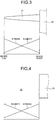
- FIG. 3 is an explanatory view regarding rigidity and a pull-off stress of a wing body.
- FIG. 4 is an explanatory view regarding rigidity and a pull-off stress around an opening.
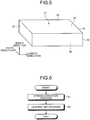
- FIG. 5 is an explanatory view regarding rigidity and a pull-off stress of a tank.
- FIG. 6 is an explanatory diagram of a forming method for a composite structure according to a first embodiment.
- An aircraft 1 illustrated in FIG. 1 is formed of a composite structure 10.
- the composite structure 10 is applied to a main wing 21, a horizontal stabilizer 23, a vertical stabilizer 24, or a fuselage 22.
- a stress to be applied is different.
- the stresses applied to blade ends of the wing bodies of the main wing 21, the horizontal stabilizer 23, and the vertical stabilizer 24 formed of the composite structure 10 are larger than those applied to blade roots. This will be described in detail below.
- an opening 25 such as a window and a door is formed, and a stress to be applied around the opening 25 is large.
- the composite structure 10 is described with reference to FIG. 2 .
- the composite structure 10 includes first composite materials 11, a second composite material 12, and corner fillet parts 13.
- the first composite material 11 and the second composite material 12 are formed of carbon fiber reinforced plastic (CFRP).
- CFRP carbon fiber reinforced plastic
- materials of the first composite material 11 and the second composite material 12 are not especially limited when they are formed of a composite material using resin and fibers.
- the first composite material 11 is formed in a plate-like shape, and the pair of first composite materials 11 is provided so that plate surfaces are opposed to each other.
- the first composite material 11 is applied to a skin (outer plate) provided on the wing body and the fuselage 22 of the aircraft 1.
- the second composite material 12 is provided between the pair of first composite materials 11.
- the second composite material 12 is applied to stringers provided in the wing body and the fuselage 22 of the aircraft.
- the second composite material 12 includes a contact part 12a having contact with one of the first composite materials 11, a contact part 12b having contact with the other first composite material 11, a longitudinal part 12c provided across a space between the pair of first composite materials 11, a bent part 12d between the contact part 12a and the longitudinal part 12c, and a bent part 12e between the contact part 12b and the longitudinal part 12c.
- the second composite material 12 is formed to be extended in a depth direction which is the front-back direction in FIG. 2 .
- the contact part 12a is provided along a plate surface of one of the first composite materials 11.
- the contact part 12b is provided along a plate surface of the other first composite material 11.
- the direction in which the pair of first composite materials 11 faces each other is a thickness direction (vertical direction in FIG. 2 ), and the direction perpendicular to the depth direction and the thickness direction is a width direction (horizontal direction in FIG. 2 ).
- the contact parts 12a and 12b are alternately arranged in the width direction.
- the longitudinal part 12c is arranged to be extended in the thickness direction.
- the bent part 12d couples the contact part 12a with the longitudinal part 12c, and a section, which is perpendicular to the depth direction, of the bent part 12d is formed to have a predetermined radius of curvature.
- the bent part 12e couples the contact part 12b with the longitudinal part 12c, and a section, which is perpendicular to the depth direction, of the bent part 12d is formed to have a predetermined radius of curvature.
- the second composite material 12 is formed in a hat-like shape by integrally and continuously forming the contact parts 12a and 12b, the longitudinal part 12c, and the bent parts 12d and 12e.
- An adhesive layer 17 is provided between each first composite material 11 and the second composite material 12.
- the adhesive layer 17 bonds each first composite material 11 and the contact parts 12a and 12b of the second composite material 12.
- the adhesive layer 17 is formed by thermally curing a film adhesive arranged between the first composite material 11 and the second composite material 12 before cured.
- the first composite material 11 and the second composite material 12 bonded via the adhesive layer 17 form corner parts 15 outside the bent parts 12d and 12e in the radial direction.
- the corner part 15 is formed to be extended in the depth direction.
- the corner fillet part 13 is provided in the corner part 15 to improve a peeling strength between the first composite material 11 and the second composite material 12.
- the shapes of the first composite materials 11 and the second composite material 12 are not limited to those illustrated in FIG. 2 . Any shapes can be used when the first composite materials 11 and the second composite material 12 can form the corner part 15. Also, the shape of the corner part 15 is not limited to the shape illustrated in FIG. 2 , the corner part 15 may be formed in any shape.
- the corner fillet part 13 is provided at the corner part 15 between the first composite material 11 and the second composite material 12.
- the corner fillet part 13 relaxes the pull-off stress between the first composite material 11 and the second composite material 12 at the corner part 15.
- the corner fillet part 13 is formed by thermally curing a film adhesive arranged before the composite structure 10 is cured.
- the film adhesive is filled to form a design shape P so that the corner fillet part 13 becomes a previously designed design shape P.
- the outside of each of the bent parts 12d and 12e in the radial direction has a predetermined radius of curvature R, and the corner fillet part 13 is formed along each of the bent parts 12d and 12e.
- the reference L indicates the length of the base of the corner fillet part 13 having contact with the first composite material 11, and the reference h indicates the length (height) of the corner fillet part 13 in the thickness direction from the first composite material 11.
- the design shape P of the corner fillet part 13 is not limited to the above shape and may be any shape when the design shape P can relax the pull-off stress at the corner part 15.
- the corner fillet part 13 and the adhesive layer 17 are formed by using the film adhesive, the corner fillet part 13 and the adhesive layer 17 are formed as including the same material.
- the film adhesive is formed of a thermosetting resin material.
- the film adhesive has a film-like shape having a film thickness of about 0.1 mm to 0.2 mm formed by using epoxy-based resin.
- the corner fillet part 13 includes a resin material and a rigidity material.
- the film adhesive has been used as a resin material.
- a resin material having a function such as thermoplasticity may be used, and the resin material is not especially limited.
- the rigidity material may be a carbon-based material such as carbon fibers or carbon nanotubes.
- the rigidity material may be glass fibers. Also, when the carbon fibers or the glass fibers which have been cut may be used. In the following description, a thermosetting resin material is applied as a resin material and a carbon-based material is applied as a rigidity material.
- the ratio of the thermosetting resin material and the carbon-based material is adjusted based on the pull-off stress to be applied to the corner part 15. Specifically, the content of the carbon-based material in the corner fillet part 13 is decreased as the pull-off stress to be applied to the corner part 15 increases. On the other hand, the content of the carbon-based material in the corner fillet part 13 increases as the pull-off stress to be applied to the corner part 15 is decreased. Therefore, for example, when it is desired that the corner fillet part 13 function as a strength member, the content of the carbon-based material in the corner fillet part 13 becomes large.
- the corner fillet part 13 is formed of a thermosetting resin material.
- FIG. 3 a case where the composite structure 10 is applied to the main wing 21 as the wing body is described.
- a blade root of the main wing 21 is connected to the fuselage 22, and a blade end of the main wing 21 is a free end.
- the displacement of the blade root is small, and the displacement increases as it goes toward the blade end.
- the pull-off stress applied to the main wing 21 is small on the side of the blade root, and the pull-off stress increases as it goes toward the blade end.
- the rigidity of the corner fillet part 13 is adjusted to be high at the blade root and to be decreased as it goes toward the blade end. Therefore, regarding the corner fillet part 13 provided in the main wing 21, the content of the carbon-based material at the blade root is large, and the content of the carbon-based material is decreased as it goes toward the blade end. This is because the following capability of the corner fillet part 13 relative to the displacement of the blade end is improved at the blade end of the main wing 21 where the displacement is large. Also, this is because the corner fillet part 13 functions as a strength member at the blade root of the main wing 21 where the displacement is small.
- the opening 25 such as a window and a door is formed in the fuselage 22.
- the displacement at an opening edge along the opening 25 is large, and the displacement is decreased with distance from the opening 25.
- the pull-off stress to be applied to the fuselage 22 is large on the side of the opening 25 and is decreased with distance from the opening 25.
- the rigidity of the corner fillet part 13 is adjusted to be low on the side of the opening 25 (opening edge) and to be increased with distance from the opening 25. Therefore, regarding the corner fillet part 13 provided in the fuselage 22, the content of the carbon-based material on the side of the opening 25 is small, and the content of the carbon-based material increases with distance from the opening 25. This is because the following capability of the corner fillet part 13 relative to the displacement of the opening edge is improved on the side of the opening 25 of the fuselage 22 where the displacement is large. Also, this is because the corner fillet part 13 functions as a strength member in the fuselage 22 which is separated from the opening 25 and where the displacement is small.
- the tank 27 is formed in a rectangular box-like shape. Here, directions in a three-dimensional orthogonal coordinate system are respectively indicated as the length direction, the width direction, and the height direction.
- the tank 27 includes two wall surfaces 29 perpendicular to the length direction, two wall surfaces 29 perpendicular to the width direction, and two wall surfaces 29 perpendicular to the height direction.
- the tank 27 is formed by bonding the six wall surfaces 29 as the wall surfaces cross with each other.
- the tank 27 needs high rigidity. Also, in the tank 27, a displacement at the center part in the length direction is large due to an internal pressure. Therefore, the rigidity of the corner fillet part 13 is adjusted to be low at the center part of the tank 27 in the length direction and to be high at the intersection parts 30 of the tank 27. Therefore, regarding the corner fillet part 13 provided in the tank 27, the content of the carbon-based material at the center part of the tank 27 in the length direction is small, and the content of the carbon-based material at the intersection part 30 of the tank 27 is large.
- step S1 stress derivation process
- step S2 content set process
- step S2 content set process
- the rigidity can be adjusted to be low by decreasing the content of the carbon-based material in the corner fillet part 13. Therefore, the corner fillet part 13 can prevent an increase in the stress and can preferably follow the displacement of the corner part 15.
- the rigidity can be adjusted to be high by increasing the content of the carbon-based material in the corner fillet part 13. Therefore, the corner fillet part 13 can function as a strength member.
- the rigidity can be adjusted to be low by decreasing the content of the carbon-based material in the corner fillet part 13. Therefore, the corner fillet part 13 can prevent an increase in the stress and can preferably follow the displacement of the blade end.
- the displacement of the blade root of the wing body is small, and the function of the blade root as the strength member counts. Therefore, the rigidity can be adjusted to be high by increasing the content of the carbon-based material in the corner fillet part 13.
- the corner fillet part 13 can prevent an increase in the stress and can preferably follow the displacement around the opening 25.
- the rigidity of the intersection part 30 of the tank 27 can be adjusted to be high by increasing the content of the carbon-based material in the corner fillet part. Therefore, the intersection part 30 of the tank 27 can function as a strength member.
- the film adhesive has been used as a thermosetting resin material forming the corner fillet part 13.
- the material of the corner fillet part 13 is not especially limited.
- the rigidity of the corner fillet part 13 is adjusted by adjusting the content of the carbon-based material relative to the thermosetting resin material and the carbon-based material included in the corner fillet part 13.
- the structure is not limited to this.
- the rigidity of the corner fillet part 13 may be adjusted by changing the kind of the material to be used as the resin material and the rigidity material, and the rigidity may be adjusted by changing the shape or the size of the corner fillet part.
Landscapes
- Engineering & Computer Science (AREA)
- Mechanical Engineering (AREA)
- Aviation & Aerospace Engineering (AREA)
- Chemical & Material Sciences (AREA)
- Composite Materials (AREA)
- Moulding By Coating Moulds (AREA)
Abstract
Description
- The present invention relates to a composite structure having a corner part, an aircraft, and a design method for a corner fillet part.
- Traditionally, a composite hat stiffener has been known as a composite structure having a corner part (for example, refer to Patent Literature 1). The composite hat stiffener includes a composite hat section, a plurality of composite stiffening plies bonded to the composite hat section, and a noodle-shaped corner filler. The noodle-shaped corner filler is arranged in a substantially triangular noodle-shaped corner filler region formed by the plurality of composite stiffening plies. Accordingly, the noodle-shaped corner filler prevents from being pulled off by the pull-off loads (pull-off stress).
- Patent Literature 1:
Japanese Laid-open Patent Publication No. 2014-12403 - Here, the noodle-shaped corner filler is generally formed by bundling prepregs which are formed by impregnating carbon fibers with resin. Here, the prepreg is formed of carbon fibers aligned in one direction, and is formed by bundling noodle-like prepregs. Therefore, the rigidity of the noodle-shaped corner filler is almost constant along a direction in which the corner filler is arranged. The pull-off load to be applied to the part where the noodle-shaped corner filler is arranged is not uniform in the direction in which the corner filler is arranged. For example, there is a case where the part where the noodle-shaped corner filler arranges is largely displaced (bent). In this case, the pull-off load at the part becomes large. At this time, since the rigidity of the noodle-shaped corner filler is almost constant, it is difficult to adjust the rigidity according to the part where the corner filler is arranged. Therefore, in a case where the rigidity of the noodle-shaped corner filler is high, the stress is increased when the noodle-shaped corner filler follows the displacement of the part.
- Therefore, a purpose of the present invention is to provide a composite structure, an aircraft, and a design method for a corner fillet part in which rigidity of the corner fillet part can be preferably adjusted.
- A composite structure of this disclosure comprises: a first composite material; a second composite material configured to be bonded to the first composite material; and a corner fillet part configured to be provided at a corner part formed by the first composite material and the second composite material, wherein rigidity of the corner fillet part is able to be adjusted, and a pull-off stress to be applied to the corner part is adjusted by adjusting the rigidity of the corner fillet part.
- With this structure, by a displacing a corner part largely, even when a pull-off stress to be applied to the corner part increases, an increase in the stress can be prevented and the corner fillet part can preferably follow the displacement of the corner part, by decreasing rigidity of the corner fillet part. On the other hand, when the pull-off stress to be applied to the corner part is small, the corner fillet part can function as a strength member by increasing the rigidity of the corner fillet part.
- It is preferable that the pull-off stress to be applied to the corner part is adjusted to be decreased by adjusting the rigidity of the corner fillet part to be decreased.
- With this structure, the increase in the pull-off stress to be applied to the corner part can be prevented by decreasing the rigidity of the corner fillet part.
- It is preferable that the corner fillet part includes at least a resin material out of the resin material and a rigidity material, and the rigidity is adjusted based on a content of the rigidity material relative to the resin material and the rigidity material.
- With this structure, the rigidity can be adjusted to be low by decreasing a content of a rigidity material in the corner fillet part. Also, the rigidity can be adjusted to be high by increasing the content of the rigidity material in the corner fillet part. For example, the resin material is a material having a function such as thermosetting property and thermoplasticity. Also, for example, carbon fibers and glass fibers are used as the rigidity material. The resin material and the rigidity material are not limited to those described above.
- It is preferable that the corner fillet part includes at least a resin material out of the resin material and a rigidity material, and the rigidity is adjusted based on kinds of materials used as the resin material and the rigidity material.
- With this structure, the rigidity can be adjusted by changing the kinds of the resin material and the rigidity material in the corner fillet part.
- It is preferable that the rigidity of the corner fillet part is adjusted based on a shape or a size of the corner fillet part.
- With this structure, the rigidity can be adjusted by changing the shape or the size of the corner fillet part.
- An aircraft of this disclosure is an aircraft in which the composite structure is used for a wing body, wherein the rigidity of the corner fillet part is decreased with distance from a blade root of the wing body toward a blade end.
- With this structure, since a displacement of a blade end of a wing body is large, even when a pull-off stress to be applied to a corner part of the blade end is large, the rigidity of the corner fillet part can be small. Therefore, the increase in the stress to be applied to the corner fillet part can be prevented, and the corner fillet part can preferably follow the displacement of the blade end. On the other hand, the displacement of the blade root of the wing body is small, and the function of the blade root as the strength member counts. Therefore, the corner fillet part can function as a strength member by increasing the rigidity of the corner fillet part.
- An aircraft of this disclosure is an aircraft using the composite structure, wherein an opening is provided in the composite structure, and the rigidity of the corner fillet part is decreased as the corner fillet part goes closer to the opening.
- With this structure, since a displacement around an opening is large, even when a pull-off stress to be applied to a corner part around the opening is large, the rigidity of the corner fillet part can be small. Therefore, the increase in the stress to be applied to the corner fillet part can be prevented, and the corner fillet part can preferably follow the displacement around the opening.
- An aircraft of this disclosure is an aircraft using the composite structure for a tank, wherein the tank is formed in a rectangular box-like shape having wall surfaces perpendicular to a length direction, a width direction, and a height direction, and the rigidity of the corner fillet part increases at intersection parts where the wall surfaces cross with each other, and the rigidity of the center part of the tank in the length direction is smaller than that of the intersection part.
- With this structure, since a displacement of a center part of a tank in the length direction is large, even when a pull-off stress to be applied to the center part of the tank is large, the rigidity of the corner fillet part can be small. Therefore, the increase in the stress to be applied to the corner fillet part can be prevented, and the corner fillet part can preferably follow the displacement of the center part of the tank. On the other hand, a function as a strength member is important for intersection parts of the tank. Therefore, the corner fillet part can function as a strength member by increasing the rigidity of the corner fillet part.
- A design method for a corner fillet part of this invention is a design method for a corner fillet part for designing the corner fillet part provided at a corner part formed by a first composite material and a second composite material, wherein the corner fillet part is able to be adjusted, and a pull-off stress to be applied to the corner part is adjusted by adjusting the rigidity of the corner fillet part.
- With this structure, by a large displacement of the corner part, even when the pull-off stress to be applied to the corner part is large, the increase in the stress to be applied to the corner fillet part can be prevented by decreasing the rigidity of the corner fillet part. On the other hand, when the pull-off stress to be applied to the corner part is small, the corner fillet part can function as a strength member by increasing the rigidity of the corner fillet part.
-
-
FIG. 1 is a perspective view of an aircraft to which a composite structure according to the present embodiment has been applied. -
FIG. 2 is a sectional view of the cured composite structure according to the present embodiment. -
FIG. 3 is an explanatory view regarding rigidity and a pull-off stress of a wing body. -
FIG. 4 is an explanatory view regarding rigidity and a pull-off stress around an opening. -
FIG. 5 is an explanatory view regarding rigidity and a pull-off stress of a tank. -
FIG. 6 is an explanatory diagram of a forming method for a composite structure according to a first embodiment. Description of Embodiments - An embodiment according to the present invention is described in detail below with reference to the drawings. The present invention is not limited to the embodiment. Also, components of the embodiment below include components which can be easily replaced by those skilled in the art and components which are substantially the same as those of the embodiment. In addition, the components described below can be appropriately combined with each other. Also, when there is a plurality of embodiments, the embodiments can be combined with each other.
-
FIG. 1 is a perspective view of an aircraft to which a composite structure according to the present embodiment has been applied.FIG. 2 is a sectional view of the cured composite structure according to the present embodiment.FIG. 3 is an explanatory view regarding rigidity and a pull-off stress of a wing body.FIG. 4 is an explanatory view regarding rigidity and a pull-off stress around an opening.FIG. 5 is an explanatory view regarding rigidity and a pull-off stress of a tank.FIG. 6 is an explanatory diagram of a forming method for a composite structure according to a first embodiment. - An
aircraft 1 illustrated inFIG. 1 is formed of acomposite structure 10. For example, thecomposite structure 10 is applied to amain wing 21, ahorizontal stabilizer 23, avertical stabilizer 24, or afuselage 22. According to a part of theaircraft 1, a stress to be applied is different. For example, the stresses applied to blade ends of the wing bodies of themain wing 21, thehorizontal stabilizer 23, and thevertical stabilizer 24 formed of thecomposite structure 10 are larger than those applied to blade roots. This will be described in detail below. Also, in thefuselage 22 formed of thecomposite structure 10, anopening 25 such as a window and a door is formed, and a stress to be applied around theopening 25 is large. First, thecomposite structure 10 is described with reference toFIG. 2 . - As illustrated in
FIG. 2 , thecomposite structure 10 includes firstcomposite materials 11, a secondcomposite material 12, andcorner fillet parts 13. - The first
composite material 11 and the secondcomposite material 12 are formed of carbon fiber reinforced plastic (CFRP). In the present embodiment, the firstcomposite material 11 and the secondcomposite material 12 are formed of CFRP. However, materials of the firstcomposite material 11 and the secondcomposite material 12 are not especially limited when they are formed of a composite material using resin and fibers. The firstcomposite material 11 is formed in a plate-like shape, and the pair of firstcomposite materials 11 is provided so that plate surfaces are opposed to each other. For example, the firstcomposite material 11 is applied to a skin (outer plate) provided on the wing body and thefuselage 22 of theaircraft 1. - The second
composite material 12 is provided between the pair of firstcomposite materials 11. For example, the secondcomposite material 12 is applied to stringers provided in the wing body and thefuselage 22 of the aircraft. The secondcomposite material 12 includes acontact part 12a having contact with one of the firstcomposite materials 11, acontact part 12b having contact with the other firstcomposite material 11, alongitudinal part 12c provided across a space between the pair of firstcomposite materials 11, abent part 12d between thecontact part 12a and thelongitudinal part 12c, and abent part 12e between thecontact part 12b and thelongitudinal part 12c. The secondcomposite material 12 is formed to be extended in a depth direction which is the front-back direction inFIG. 2 . - The
contact part 12a is provided along a plate surface of one of the firstcomposite materials 11. Thecontact part 12b is provided along a plate surface of the other firstcomposite material 11. Here, the direction in which the pair of firstcomposite materials 11 faces each other is a thickness direction (vertical direction inFIG. 2 ), and the direction perpendicular to the depth direction and the thickness direction is a width direction (horizontal direction inFIG. 2 ). At this time, thecontact parts longitudinal part 12c is arranged to be extended in the thickness direction. Thebent part 12d couples thecontact part 12a with thelongitudinal part 12c, and a section, which is perpendicular to the depth direction, of thebent part 12d is formed to have a predetermined radius of curvature. Thebent part 12e couples thecontact part 12b with thelongitudinal part 12c, and a section, which is perpendicular to the depth direction, of thebent part 12d is formed to have a predetermined radius of curvature. The secondcomposite material 12 is formed in a hat-like shape by integrally and continuously forming thecontact parts longitudinal part 12c, and thebent parts - An
adhesive layer 17 is provided between each firstcomposite material 11 and the secondcomposite material 12. Theadhesive layer 17 bonds each firstcomposite material 11 and thecontact parts composite material 12. Theadhesive layer 17 is formed by thermally curing a film adhesive arranged between the firstcomposite material 11 and the secondcomposite material 12 before cured. - The first
composite material 11 and the secondcomposite material 12 bonded via theadhesive layer 17form corner parts 15 outside thebent parts corner part 15 is formed to be extended in the depth direction. Thecorner fillet part 13 is provided in thecorner part 15 to improve a peeling strength between the firstcomposite material 11 and the secondcomposite material 12. The shapes of the firstcomposite materials 11 and the secondcomposite material 12 are not limited to those illustrated inFIG. 2 . Any shapes can be used when the firstcomposite materials 11 and the secondcomposite material 12 can form thecorner part 15. Also, the shape of thecorner part 15 is not limited to the shape illustrated inFIG. 2 , thecorner part 15 may be formed in any shape. - The
corner fillet part 13 is provided at thecorner part 15 between the firstcomposite material 11 and the secondcomposite material 12. Thecorner fillet part 13 relaxes the pull-off stress between the firstcomposite material 11 and the secondcomposite material 12 at thecorner part 15. Thecorner fillet part 13 is formed by thermally curing a film adhesive arranged before thecomposite structure 10 is cured. The film adhesive is filled to form a design shape P so that thecorner fillet part 13 becomes a previously designed design shape P. Here, the outside of each of thebent parts corner fillet part 13 is formed along each of thebent parts - Specifically, in the design shape P of the
corner fillet part 13, a surface having contact with the second composite material 12 (bent parts corner fillet part 13 in the present embodiment is expressed by "S = L × h - πR2/2". The reference L indicates the length of the base of thecorner fillet part 13 having contact with the firstcomposite material 11, and the reference h indicates the length (height) of thecorner fillet part 13 in the thickness direction from the firstcomposite material 11. The design shape P of thecorner fillet part 13 is not limited to the above shape and may be any shape when the design shape P can relax the pull-off stress at thecorner part 15. - At this time, since the
corner fillet part 13 and theadhesive layer 17 are formed by using the film adhesive, thecorner fillet part 13 and theadhesive layer 17 are formed as including the same material. Here, the film adhesive is formed of a thermosetting resin material. For example, the film adhesive has a film-like shape having a film thickness of about 0.1 mm to 0.2 mm formed by using epoxy-based resin. Thecorner fillet part 13 includes a resin material and a rigidity material. In the present embodiment, the film adhesive has been used as a resin material. However, for example, a resin material having a function such as thermoplasticity may be used, and the resin material is not especially limited. Also, for example, the rigidity material may be a carbon-based material such as carbon fibers or carbon nanotubes. Also, the rigidity material may be glass fibers. Also, when the carbon fibers or the glass fibers which have been cut may be used. In the following description, a thermosetting resin material is applied as a resin material and a carbon-based material is applied as a rigidity material. - Here, in the
corner fillet part 13, the ratio of the thermosetting resin material and the carbon-based material is adjusted based on the pull-off stress to be applied to thecorner part 15. Specifically, the content of the carbon-based material in thecorner fillet part 13 is decreased as the pull-off stress to be applied to thecorner part 15 increases. On the other hand, the content of the carbon-based material in thecorner fillet part 13 increases as the pull-off stress to be applied to thecorner part 15 is decreased. Therefore, for example, when it is desired that thecorner fillet part 13 function as a strength member, the content of the carbon-based material in thecorner fillet part 13 becomes large. On the other hand, when it is desired to improve a following capability relative to a displacement of the member of thecorner part 15, the content of the carbon-based material in thecorner fillet part 13 becomes small. A case where the content of the carbon-based material is small includes a case where the content is zero percent. In this case, thecorner fillet part 13 is formed of a thermosetting resin material. - Next, the rigidity and the pull-off stress P of the
corner fillet part 13 when thecomposite structure 10 is applied to the wing body are described with reference toFIG. 3 . InFIG. 3 , a case where thecomposite structure 10 is applied to themain wing 21 as the wing body is described. A blade root of themain wing 21 is connected to thefuselage 22, and a blade end of themain wing 21 is a free end. Regarding themain wing 21, the displacement of the blade root is small, and the displacement increases as it goes toward the blade end. - As illustrated in
FIG. 3 , the pull-off stress applied to themain wing 21 is small on the side of the blade root, and the pull-off stress increases as it goes toward the blade end. In contrast to the pull-off stress, the rigidity of thecorner fillet part 13 is adjusted to be high at the blade root and to be decreased as it goes toward the blade end. Therefore, regarding thecorner fillet part 13 provided in themain wing 21, the content of the carbon-based material at the blade root is large, and the content of the carbon-based material is decreased as it goes toward the blade end. This is because the following capability of thecorner fillet part 13 relative to the displacement of the blade end is improved at the blade end of themain wing 21 where the displacement is large. Also, this is because thecorner fillet part 13 functions as a strength member at the blade root of themain wing 21 where the displacement is small. - Next, the rigidity and the pull-off stress of the
corner fillet part 13 when thecomposite structure 10 is applied to thefuselage 22 are described with reference toFIG. 4 . Theopening 25 such as a window and a door is formed in thefuselage 22. In thefuselage 22, the displacement at an opening edge along theopening 25 is large, and the displacement is decreased with distance from theopening 25. - As illustrated in
FIG. 4 , the pull-off stress to be applied to thefuselage 22 is large on the side of theopening 25 and is decreased with distance from theopening 25. In contrast to the pull-off stress, the rigidity of thecorner fillet part 13 is adjusted to be low on the side of the opening 25 (opening edge) and to be increased with distance from theopening 25. Therefore, regarding thecorner fillet part 13 provided in thefuselage 22, the content of the carbon-based material on the side of theopening 25 is small, and the content of the carbon-based material increases with distance from theopening 25. This is because the following capability of thecorner fillet part 13 relative to the displacement of the opening edge is improved on the side of theopening 25 of thefuselage 22 where the displacement is large. Also, this is because thecorner fillet part 13 functions as a strength member in thefuselage 22 which is separated from theopening 25 and where the displacement is small. - Next, the rigidity and the pull-off stress of the
corner fillet part 13 when thecomposite structure 10 is applied to atank 27 to store fuel and the like are described with reference toFIG. 5 . Thetank 27 is formed in a rectangular box-like shape. Here, directions in a three-dimensional orthogonal coordinate system are respectively indicated as the length direction, the width direction, and the height direction. Thetank 27 includes twowall surfaces 29 perpendicular to the length direction, twowall surfaces 29 perpendicular to the width direction, and twowall surfaces 29 perpendicular to the height direction. Thetank 27 is formed by bonding the sixwall surfaces 29 as the wall surfaces cross with each other. - To make an
intersection part 30 where the wall surfaces 29 cross with each other function as a strength member, thetank 27 needs high rigidity. Also, in thetank 27, a displacement at the center part in the length direction is large due to an internal pressure. Therefore, the rigidity of thecorner fillet part 13 is adjusted to be low at the center part of thetank 27 in the length direction and to be high at theintersection parts 30 of thetank 27. Therefore, regarding thecorner fillet part 13 provided in thetank 27, the content of the carbon-based material at the center part of thetank 27 in the length direction is small, and the content of the carbon-based material at theintersection part 30 of thetank 27 is large. - Next, a design method for the
corner fillet part 13 is described with reference toFIG. 6 . First, in theaircraft 1, a pull-off stress to be applied to a structure such as the wing body including themain wing 21 and thefuselage 22 is derived (step S1: stress derivation process). Next, the rigidity of thecorner fillet part 13 is set so that the derived pull-off stress becomes an appropriate stress, and the content of the carbon-based material included in thecorner fillet part 13 is set based on the set rigidity (step S2: content set process). Then, the ratio of the thermosetting resin material and the carbon-based material in thecorner fillet part 13 is set based on the content of the carbon-based material which has been set in the content set process. Thecorner fillet part 13 is formed by thermally curing the materials with this ratio. - As described above, according to the present embodiment, with a large displacement of the
corner part 15, even when the pull-off stress to be applied to thecorner part 15 is large, the rigidity can be adjusted to be low by decreasing the content of the carbon-based material in thecorner fillet part 13. Therefore, thecorner fillet part 13 can prevent an increase in the stress and can preferably follow the displacement of thecorner part 15. On the other hand, when the pull-off stress to be applied to thecorner part 15 is small, the rigidity can be adjusted to be high by increasing the content of the carbon-based material in thecorner fillet part 13. Therefore, thecorner fillet part 13 can function as a strength member. - Also, according to the present embodiment, since the displacement of the blade end of the wing body such as the
main wing 21 is large, even when the pull-off stress to be applied to thecorner part 15 of the blade end is large, the rigidity can be adjusted to be low by decreasing the content of the carbon-based material in thecorner fillet part 13. Therefore, thecorner fillet part 13 can prevent an increase in the stress and can preferably follow the displacement of the blade end. On the other hand, the displacement of the blade root of the wing body is small, and the function of the blade root as the strength member counts. Therefore, the rigidity can be adjusted to be high by increasing the content of the carbon-based material in thecorner fillet part 13. - Also, according to the present embodiment, since the displacement around the
opening 25 of thefuselage 22 is large, even when the pull-off stress to be applied to thecorner part 15 around theopening 25 is large, the rigidity can be adjusted to be low by decreasing the content of the carbon-based material in thecorner fillet part 13. Therefore, thecorner fillet part 13 can prevent an increase in the stress and can preferably follow the displacement around theopening 25. - Also, according to the present embodiment, since the displacement of the center part of the
tank 27 in the length direction is large, even when the pull-off stress to be applied to the center part of thetank 27 is large, the rigidity can be adjusted to be low by decreasing the content of the carbon-based material in thecorner fillet part 13. Therefore, thecorner fillet part 13 can prevent an increase in the stress and can preferably follow the displacement of the center part of thetank 27. On the other hand, the rigidity of theintersection part 30 of thetank 27 can be adjusted to be high by increasing the content of the carbon-based material in the corner fillet part. Therefore, theintersection part 30 of thetank 27 can function as a strength member. - In the present embodiment, the film adhesive has been used as a thermosetting resin material forming the
corner fillet part 13. However, the material of thecorner fillet part 13 is not especially limited. - Also, in the present embodiment, the rigidity of the
corner fillet part 13 is adjusted by adjusting the content of the carbon-based material relative to the thermosetting resin material and the carbon-based material included in thecorner fillet part 13. However, the structure is not limited to this. For example, the rigidity of thecorner fillet part 13 may be adjusted by changing the kind of the material to be used as the resin material and the rigidity material, and the rigidity may be adjusted by changing the shape or the size of the corner fillet part. -
- 1
- AIRCRAFT
- 10
- COMPOSITE STRUCTURE
- 11
- FIRST COMPOSITE MATERIAL
- 12
- SECOND COMPOSITE MATERIAL
- 13
- CORNER FILLET PART
- 15
- CORNER PART
- 17
- ADHESIVE LAYER
- 21
- MAIN WING
- 22
- FUSELAGE
- 25
- OPENING
- 27
- TANK
- 29
- WALL SURFACE
- 30
- INTERSECTION PART
- P
- DESIGN SHAPE
- S
- AREA OF DESIGN SHAPE
- L
- BASE OF DESIGN SHAPE
- h
- HEIGHT OF DESIGN SHAPE
Claims (9)
- A composite structure comprising:a first composite material;a second composite material configured to be bonded to the first composite material; anda corner fillet part configured to be provided at a corner part formed by the first composite material and the second composite material, whereinrigidity of the corner fillet part is able to be adjusted, and a pull-off stress to be applied to the corner part is adjusted by adjusting the rigidity of the corner fillet part.
- The composite structure according to claim 1, wherein
the pull-off stress to be applied to the corner part is adjusted to be decreased by adjusting the rigidity of the corner fillet part to be decreased. - The composite structure according to claim 1 or 2, wherein
the corner fillet part includes at least a resin material out of the resin material and a rigidity material, and
the rigidity is adjusted based on a content of the rigidity material relative to the resin material and the rigidity material. - The composite structure according to claim 1 or 2, wherein
the corner fillet part includes at least a resin material out of the resin material and a rigidity material, and
the rigidity is adjusted based on kinds of materials used as the resin material and the rigidity material. - The composite structure according to claim 1 or 2, wherein
the rigidity of the corner fillet part is adjusted based on a shape or a size of the corner fillet part. - An aircraft in which the composite structure according to any one of claims 1 to 5 is used for a wing body, wherein
the rigidity of the corner fillet part is decreased with distance from a blade root of the wing body toward a blade end. - An aircraft using the composite structure according to any one of claims 1 to 5, wherein
an opening is provided in the composite structure, and the rigidity of the corner fillet part is decreased as the corner fillet part goes closer to the opening. - An aircraft using the composite structure according to any one of claims 1 to 5 for a tank, wherein
the tank is formed in a rectangular box-like shape having wall surfaces perpendicular to a length direction, a width direction, and a height direction, and
the rigidity of the corner fillet part increases at intersection parts where the wall surfaces cross with each other, and the rigidity of the center part of the tank in the length direction is smaller than that of the intersection part. - A design method for a corner fillet part for designing the corner fillet part provided at a corner part formed by a first composite material and a second composite material, wherein
the corner fillet part is able to be adjusted, and a pull-off stress to be applied to the corner part is adjusted by adjusting the rigidity of the corner fillet part.
Applications Claiming Priority (2)
| Application Number | Priority Date | Filing Date | Title |
|---|---|---|---|
| JP2014253459A JP6501511B2 (en) | 2014-12-15 | 2014-12-15 | Design method of corner fillet section and aircraft |
| PCT/JP2015/079651 WO2016098442A1 (en) | 2014-12-15 | 2015-10-21 | Composite structure, aircraft, and method for designing corner fillet section |
Publications (3)
| Publication Number | Publication Date |
|---|---|
| EP3210764A1 true EP3210764A1 (en) | 2017-08-30 |
| EP3210764A4 EP3210764A4 (en) | 2017-11-29 |
| EP3210764B1 EP3210764B1 (en) | 2019-06-19 |
Family
ID=56126344
Family Applications (1)
| Application Number | Title | Priority Date | Filing Date |
|---|---|---|---|
| EP15869650.0A Active EP3210764B1 (en) | 2014-12-15 | 2015-10-21 | Composite structure, aircraft, and method for designing corner fillet section |
Country Status (4)
| Country | Link |
|---|---|
| US (1) | US20170259519A1 (en) |
| EP (1) | EP3210764B1 (en) |
| JP (1) | JP6501511B2 (en) |
| WO (1) | WO2016098442A1 (en) |
Families Citing this family (2)
| Publication number | Priority date | Publication date | Assignee | Title |
|---|---|---|---|---|
| US10875625B2 (en) * | 2017-08-23 | 2020-12-29 | The Boeing Company | Co-cured spar and stringer center wing box |
| CN116834321B (en) * | 2023-06-06 | 2025-07-11 | 四川腾凤科技有限公司 | Technological method for reinforcing bonding of composite material plate ribs |
Family Cites Families (15)
| Publication number | Priority date | Publication date | Assignee | Title |
|---|---|---|---|---|
| AT398064B (en) * | 1992-07-01 | 1994-09-26 | Hoac Austria Flugzeugwerk Wr N | PLASTIC COMPOSITE PROFILE, ESPECIALLY WING SLEEVE FOR AIRCRAFT CONSTRUCTION |
| AU2001262912A1 (en) * | 2000-02-25 | 2001-09-03 | The Boeing Company | Laminated composite radius filler |
| US6849150B1 (en) * | 2001-01-16 | 2005-02-01 | Lockheed Martin Corporation | System and method of forming structural assemblies with 3-D woven joint pre-forms |
| JP4713780B2 (en) * | 2001-07-27 | 2011-06-29 | 富士重工業株式会社 | Reinforcing panel manufacturing method |
| JP2005337272A (en) * | 2004-05-24 | 2005-12-08 | Murata Mach Ltd | FRP pressure vessel |
| JP2006181751A (en) * | 2004-12-27 | 2006-07-13 | Toho Tenax Co Ltd | Hollow rectangular parallelepiped made of frp whose one surface is opened and its manufacturing method |
| NL1033895C2 (en) * | 2007-05-25 | 2008-11-28 | Fits Holding B V | Method for manufacturing an object from a sandwich structure with a reinforced angle and such an object. |
| DE102008008200B4 (en) * | 2008-01-31 | 2014-03-13 | Deutsches Zentrum für Luft- und Raumfahrt e.V. | Composite structure and method for its production |
| US8714485B2 (en) * | 2009-12-15 | 2014-05-06 | The Boeing Company | Method of fabricating a hat stringer |
| GB201005308D0 (en) * | 2010-03-30 | 2010-05-12 | Airbus Operations Ltd | Composite structural member |
| US8182640B1 (en) * | 2010-05-13 | 2012-05-22 | Textron Innovations, Inc. | Process for bonding components to a surface |
| US8628717B2 (en) * | 2010-06-25 | 2014-01-14 | The Boeing Company | Composite structures having integrated stiffeners and method of making the same |
| US20130004715A1 (en) * | 2011-06-29 | 2013-01-03 | United Technologies Corporation | Reinforced composite t-joint |
| US8758879B2 (en) * | 2012-06-24 | 2014-06-24 | The Boeing Company | Composite hat stiffener, composite hat-stiffened pressure webs, and methods of making the same |
| US10308343B2 (en) * | 2013-05-30 | 2019-06-04 | The Boeing Company | Composite hat stiffener |
-
2014
- 2014-12-15 JP JP2014253459A patent/JP6501511B2/en active Active
-
2015
- 2015-10-21 WO PCT/JP2015/079651 patent/WO2016098442A1/en not_active Ceased
- 2015-10-21 US US15/529,313 patent/US20170259519A1/en not_active Abandoned
- 2015-10-21 EP EP15869650.0A patent/EP3210764B1/en active Active
Also Published As
| Publication number | Publication date |
|---|---|
| US20170259519A1 (en) | 2017-09-14 |
| EP3210764B1 (en) | 2019-06-19 |
| WO2016098442A1 (en) | 2016-06-23 |
| EP3210764A4 (en) | 2017-11-29 |
| JP2016112786A (en) | 2016-06-23 |
| JP6501511B2 (en) | 2019-04-17 |
Similar Documents
| Publication | Publication Date | Title |
|---|---|---|
| EP3093131B1 (en) | System and method for forming composite materials | |
| US20090220747A1 (en) | Wing and blade structure using pultruded composites | |
| EP2933094B1 (en) | Method of forming radius fillers for composite structures | |
| EP3029339A1 (en) | Joint, and aircraft structure | |
| US20160244140A1 (en) | Joint, and aircraft structure | |
| JP6309324B2 (en) | Composite structure, aircraft wing and aircraft fuselage provided with the same, and method for manufacturing composite structure | |
| US20170100884A1 (en) | Fiber composite component assembly having at least two plate-shaped composite structures and processes for preparing same | |
| CN104968484A (en) | Assembly of a metal insert and a sheet of composite material, method for incorporating such an insert into such a sheet and part obtained by moulding such a sheet | |
| US10195789B2 (en) | Composite structure and method for molding composite structure | |
| US11511847B2 (en) | Skin panel of composite material having an internal grid | |
| JPWO2011043346A1 (en) | Composite structure, aircraft main wing and aircraft fuselage provided with the same | |
| WO2013129122A1 (en) | Composite material structural body, aircraft wing and aircraft body provided with same, and method of manufacturing composite material structural body | |
| CA2946360A1 (en) | Panel made of laminates and method of manufacturing the same | |
| EP3210764B1 (en) | Composite structure, aircraft, and method for designing corner fillet section | |
| JP6839284B2 (en) | Rotorcraft landing gear | |
| US8708279B2 (en) | Composite structural member with progressive rigidity | |
| US10994823B2 (en) | Beaded panels and method of forming beaded panels | |
| US10023287B2 (en) | Method for manufacturing a shell element reinforced with support elements | |
| JP6515654B2 (en) | Lap joint, method of manufacturing the same, and method of designing the same | |
| US11685503B2 (en) | Stringer assemblies and methods of forming thereof | |
| US20200262177A1 (en) | Laminated board and method for processing laminated board | |
| JPWO2019131893A1 (en) | Manufacturing methods for composite materials, laminated structures, aircraft wings and composite materials |
Legal Events
| Date | Code | Title | Description |
|---|---|---|---|
| STAA | Information on the status of an ep patent application or granted ep patent |
Free format text: STATUS: THE INTERNATIONAL PUBLICATION HAS BEEN MADE |
|
| PUAI | Public reference made under article 153(3) epc to a published international application that has entered the european phase |
Free format text: ORIGINAL CODE: 0009012 |
|
| STAA | Information on the status of an ep patent application or granted ep patent |
Free format text: STATUS: REQUEST FOR EXAMINATION WAS MADE |
|
| 17P | Request for examination filed |
Effective date: 20170522 |
|
| AK | Designated contracting states |
Kind code of ref document: A1 Designated state(s): AL AT BE BG CH CY CZ DE DK EE ES FI FR GB GR HR HU IE IS IT LI LT LU LV MC MK MT NL NO PL PT RO RS SE SI SK SM TR |
|
| AX | Request for extension of the european patent |
Extension state: BA ME |
|
| A4 | Supplementary search report drawn up and despatched |
Effective date: 20171103 |
|
| RIC1 | Information provided on ipc code assigned before grant |
Ipc: B64C 1/12 20060101ALI20171026BHEP Ipc: B29C 70/06 20060101AFI20171026BHEP Ipc: B64C 1/00 20060101ALI20171026BHEP |
|
| DAV | Request for validation of the european patent (deleted) | ||
| DAX | Request for extension of the european patent (deleted) | ||
| GRAP | Despatch of communication of intention to grant a patent |
Free format text: ORIGINAL CODE: EPIDOSNIGR1 |
|
| STAA | Information on the status of an ep patent application or granted ep patent |
Free format text: STATUS: GRANT OF PATENT IS INTENDED |
|
| INTG | Intention to grant announced |
Effective date: 20190108 |
|
| GRAS | Grant fee paid |
Free format text: ORIGINAL CODE: EPIDOSNIGR3 |
|
| GRAA | (expected) grant |
Free format text: ORIGINAL CODE: 0009210 |
|
| STAA | Information on the status of an ep patent application or granted ep patent |
Free format text: STATUS: THE PATENT HAS BEEN GRANTED |
|
| AK | Designated contracting states |
Kind code of ref document: B1 Designated state(s): AL AT BE BG CH CY CZ DE DK EE ES FI FR GB GR HR HU IE IS IT LI LT LU LV MC MK MT NL NO PL PT RO RS SE SI SK SM TR |
|
| REG | Reference to a national code |
Ref country code: GB Ref legal event code: FG4D |
|
| REG | Reference to a national code |
Ref country code: CH Ref legal event code: EP |
|
| REG | Reference to a national code |
Ref country code: IE Ref legal event code: FG4D |
|
| REG | Reference to a national code |
Ref country code: DE Ref legal event code: R096 Ref document number: 602015032502 Country of ref document: DE |
|
| REG | Reference to a national code |
Ref country code: AT Ref legal event code: REF Ref document number: 1144924 Country of ref document: AT Kind code of ref document: T Effective date: 20190715 |
|
| REG | Reference to a national code |
Ref country code: NL Ref legal event code: MP Effective date: 20190619 |
|
| PG25 | Lapsed in a contracting state [announced via postgrant information from national office to epo] |
Ref country code: NO Free format text: LAPSE BECAUSE OF FAILURE TO SUBMIT A TRANSLATION OF THE DESCRIPTION OR TO PAY THE FEE WITHIN THE PRESCRIBED TIME-LIMIT Effective date: 20190919 Ref country code: HR Free format text: LAPSE BECAUSE OF FAILURE TO SUBMIT A TRANSLATION OF THE DESCRIPTION OR TO PAY THE FEE WITHIN THE PRESCRIBED TIME-LIMIT Effective date: 20190619 Ref country code: LT Free format text: LAPSE BECAUSE OF FAILURE TO SUBMIT A TRANSLATION OF THE DESCRIPTION OR TO PAY THE FEE WITHIN THE PRESCRIBED TIME-LIMIT Effective date: 20190619 Ref country code: SE Free format text: LAPSE BECAUSE OF FAILURE TO SUBMIT A TRANSLATION OF THE DESCRIPTION OR TO PAY THE FEE WITHIN THE PRESCRIBED TIME-LIMIT Effective date: 20190619 Ref country code: AL Free format text: LAPSE BECAUSE OF FAILURE TO SUBMIT A TRANSLATION OF THE DESCRIPTION OR TO PAY THE FEE WITHIN THE PRESCRIBED TIME-LIMIT Effective date: 20190619 Ref country code: FI Free format text: LAPSE BECAUSE OF FAILURE TO SUBMIT A TRANSLATION OF THE DESCRIPTION OR TO PAY THE FEE WITHIN THE PRESCRIBED TIME-LIMIT Effective date: 20190619 |
|
| REG | Reference to a national code |
Ref country code: LT Ref legal event code: MG4D |
|
| PG25 | Lapsed in a contracting state [announced via postgrant information from national office to epo] |
Ref country code: GR Free format text: LAPSE BECAUSE OF FAILURE TO SUBMIT A TRANSLATION OF THE DESCRIPTION OR TO PAY THE FEE WITHIN THE PRESCRIBED TIME-LIMIT Effective date: 20190920 Ref country code: LV Free format text: LAPSE BECAUSE OF FAILURE TO SUBMIT A TRANSLATION OF THE DESCRIPTION OR TO PAY THE FEE WITHIN THE PRESCRIBED TIME-LIMIT Effective date: 20190619 Ref country code: BG Free format text: LAPSE BECAUSE OF FAILURE TO SUBMIT A TRANSLATION OF THE DESCRIPTION OR TO PAY THE FEE WITHIN THE PRESCRIBED TIME-LIMIT Effective date: 20190919 Ref country code: RS Free format text: LAPSE BECAUSE OF FAILURE TO SUBMIT A TRANSLATION OF THE DESCRIPTION OR TO PAY THE FEE WITHIN THE PRESCRIBED TIME-LIMIT Effective date: 20190619 |
|
| REG | Reference to a national code |
Ref country code: AT Ref legal event code: MK05 Ref document number: 1144924 Country of ref document: AT Kind code of ref document: T Effective date: 20190619 |
|
| PG25 | Lapsed in a contracting state [announced via postgrant information from national office to epo] |
Ref country code: CZ Free format text: LAPSE BECAUSE OF FAILURE TO SUBMIT A TRANSLATION OF THE DESCRIPTION OR TO PAY THE FEE WITHIN THE PRESCRIBED TIME-LIMIT Effective date: 20190619 Ref country code: RO Free format text: LAPSE BECAUSE OF FAILURE TO SUBMIT A TRANSLATION OF THE DESCRIPTION OR TO PAY THE FEE WITHIN THE PRESCRIBED TIME-LIMIT Effective date: 20190619 Ref country code: SK Free format text: LAPSE BECAUSE OF FAILURE TO SUBMIT A TRANSLATION OF THE DESCRIPTION OR TO PAY THE FEE WITHIN THE PRESCRIBED TIME-LIMIT Effective date: 20190619 Ref country code: NL Free format text: LAPSE BECAUSE OF FAILURE TO SUBMIT A TRANSLATION OF THE DESCRIPTION OR TO PAY THE FEE WITHIN THE PRESCRIBED TIME-LIMIT Effective date: 20190619 Ref country code: AT Free format text: LAPSE BECAUSE OF FAILURE TO SUBMIT A TRANSLATION OF THE DESCRIPTION OR TO PAY THE FEE WITHIN THE PRESCRIBED TIME-LIMIT Effective date: 20190619 Ref country code: PT Free format text: LAPSE BECAUSE OF FAILURE TO SUBMIT A TRANSLATION OF THE DESCRIPTION OR TO PAY THE FEE WITHIN THE PRESCRIBED TIME-LIMIT Effective date: 20191021 Ref country code: EE Free format text: LAPSE BECAUSE OF FAILURE TO SUBMIT A TRANSLATION OF THE DESCRIPTION OR TO PAY THE FEE WITHIN THE PRESCRIBED TIME-LIMIT Effective date: 20190619 |
|
| PG25 | Lapsed in a contracting state [announced via postgrant information from national office to epo] |
Ref country code: IT Free format text: LAPSE BECAUSE OF FAILURE TO SUBMIT A TRANSLATION OF THE DESCRIPTION OR TO PAY THE FEE WITHIN THE PRESCRIBED TIME-LIMIT Effective date: 20190619 Ref country code: ES Free format text: LAPSE BECAUSE OF FAILURE TO SUBMIT A TRANSLATION OF THE DESCRIPTION OR TO PAY THE FEE WITHIN THE PRESCRIBED TIME-LIMIT Effective date: 20190619 Ref country code: IS Free format text: LAPSE BECAUSE OF FAILURE TO SUBMIT A TRANSLATION OF THE DESCRIPTION OR TO PAY THE FEE WITHIN THE PRESCRIBED TIME-LIMIT Effective date: 20191019 Ref country code: SM Free format text: LAPSE BECAUSE OF FAILURE TO SUBMIT A TRANSLATION OF THE DESCRIPTION OR TO PAY THE FEE WITHIN THE PRESCRIBED TIME-LIMIT Effective date: 20190619 |
|
| PG25 | Lapsed in a contracting state [announced via postgrant information from national office to epo] |
Ref country code: TR Free format text: LAPSE BECAUSE OF FAILURE TO SUBMIT A TRANSLATION OF THE DESCRIPTION OR TO PAY THE FEE WITHIN THE PRESCRIBED TIME-LIMIT Effective date: 20190619 |
|
| PG25 | Lapsed in a contracting state [announced via postgrant information from national office to epo] |
Ref country code: PL Free format text: LAPSE BECAUSE OF FAILURE TO SUBMIT A TRANSLATION OF THE DESCRIPTION OR TO PAY THE FEE WITHIN THE PRESCRIBED TIME-LIMIT Effective date: 20190619 Ref country code: DK Free format text: LAPSE BECAUSE OF FAILURE TO SUBMIT A TRANSLATION OF THE DESCRIPTION OR TO PAY THE FEE WITHIN THE PRESCRIBED TIME-LIMIT Effective date: 20190619 |
|
| REG | Reference to a national code |
Ref country code: DE Ref legal event code: R119 Ref document number: 602015032502 Country of ref document: DE |
|
| PG25 | Lapsed in a contracting state [announced via postgrant information from national office to epo] |
Ref country code: MC Free format text: LAPSE BECAUSE OF FAILURE TO SUBMIT A TRANSLATION OF THE DESCRIPTION OR TO PAY THE FEE WITHIN THE PRESCRIBED TIME-LIMIT Effective date: 20190619 Ref country code: IS Free format text: LAPSE BECAUSE OF FAILURE TO SUBMIT A TRANSLATION OF THE DESCRIPTION OR TO PAY THE FEE WITHIN THE PRESCRIBED TIME-LIMIT Effective date: 20200224 |
|
| REG | Reference to a national code |
Ref country code: CH Ref legal event code: PL |
|
| PLBE | No opposition filed within time limit |
Free format text: ORIGINAL CODE: 0009261 |
|
| STAA | Information on the status of an ep patent application or granted ep patent |
Free format text: STATUS: NO OPPOSITION FILED WITHIN TIME LIMIT |
|
| PG2D | Information on lapse in contracting state deleted |
Ref country code: IS |
|
| PG25 | Lapsed in a contracting state [announced via postgrant information from national office to epo] |
Ref country code: LU Free format text: LAPSE BECAUSE OF NON-PAYMENT OF DUE FEES Effective date: 20191021 Ref country code: DE Free format text: LAPSE BECAUSE OF NON-PAYMENT OF DUE FEES Effective date: 20200501 Ref country code: CH Free format text: LAPSE BECAUSE OF NON-PAYMENT OF DUE FEES Effective date: 20191031 Ref country code: LI Free format text: LAPSE BECAUSE OF NON-PAYMENT OF DUE FEES Effective date: 20191031 |
|
| 26N | No opposition filed |
Effective date: 20200603 |
|
| REG | Reference to a national code |
Ref country code: BE Ref legal event code: MM Effective date: 20191031 |
|
| PG25 | Lapsed in a contracting state [announced via postgrant information from national office to epo] |
Ref country code: SI Free format text: LAPSE BECAUSE OF FAILURE TO SUBMIT A TRANSLATION OF THE DESCRIPTION OR TO PAY THE FEE WITHIN THE PRESCRIBED TIME-LIMIT Effective date: 20190619 Ref country code: BE Free format text: LAPSE BECAUSE OF NON-PAYMENT OF DUE FEES Effective date: 20191031 |
|
| PG25 | Lapsed in a contracting state [announced via postgrant information from national office to epo] |
Ref country code: IE Free format text: LAPSE BECAUSE OF NON-PAYMENT OF DUE FEES Effective date: 20191021 |
|
| PG25 | Lapsed in a contracting state [announced via postgrant information from national office to epo] |
Ref country code: CY Free format text: LAPSE BECAUSE OF FAILURE TO SUBMIT A TRANSLATION OF THE DESCRIPTION OR TO PAY THE FEE WITHIN THE PRESCRIBED TIME-LIMIT Effective date: 20190619 |
|
| PG25 | Lapsed in a contracting state [announced via postgrant information from national office to epo] |
Ref country code: HU Free format text: LAPSE BECAUSE OF FAILURE TO SUBMIT A TRANSLATION OF THE DESCRIPTION OR TO PAY THE FEE WITHIN THE PRESCRIBED TIME-LIMIT; INVALID AB INITIO Effective date: 20151021 Ref country code: MT Free format text: LAPSE BECAUSE OF FAILURE TO SUBMIT A TRANSLATION OF THE DESCRIPTION OR TO PAY THE FEE WITHIN THE PRESCRIBED TIME-LIMIT Effective date: 20190619 |
|
| PG25 | Lapsed in a contracting state [announced via postgrant information from national office to epo] |
Ref country code: MK Free format text: LAPSE BECAUSE OF FAILURE TO SUBMIT A TRANSLATION OF THE DESCRIPTION OR TO PAY THE FEE WITHIN THE PRESCRIBED TIME-LIMIT Effective date: 20190619 |
|
| PGFP | Annual fee paid to national office [announced via postgrant information from national office to epo] |
Ref country code: GB Payment date: 20250828 Year of fee payment: 11 |
|
| PGFP | Annual fee paid to national office [announced via postgrant information from national office to epo] |
Ref country code: FR Payment date: 20250908 Year of fee payment: 11 |