EP3210716A1 - Composite material and composite material manufacturing method - Google Patents
Composite material and composite material manufacturing method Download PDFInfo
- Publication number
- EP3210716A1 EP3210716A1 EP15853007.1A EP15853007A EP3210716A1 EP 3210716 A1 EP3210716 A1 EP 3210716A1 EP 15853007 A EP15853007 A EP 15853007A EP 3210716 A1 EP3210716 A1 EP 3210716A1
- Authority
- EP
- European Patent Office
- Prior art keywords
- manufacturing
- additive manufacturing
- machine tool
- composite member
- machining
- Prior art date
- Legal status (The legal status is an assumption and is not a legal conclusion. Google has not performed a legal analysis and makes no representation as to the accuracy of the status listed.)
- Granted
Links
Images






Classifications
-
- B—PERFORMING OPERATIONS; TRANSPORTING
- B23—MACHINE TOOLS; METAL-WORKING NOT OTHERWISE PROVIDED FOR
- B23K—SOLDERING OR UNSOLDERING; WELDING; CLADDING OR PLATING BY SOLDERING OR WELDING; CUTTING BY APPLYING HEAT LOCALLY, e.g. FLAME CUTTING; WORKING BY LASER BEAM
- B23K26/00—Working by laser beam, e.g. welding, cutting or boring
- B23K26/0093—Working by laser beam, e.g. welding, cutting or boring combined with mechanical machining or metal-working covered by other subclasses than B23K
-
- B—PERFORMING OPERATIONS; TRANSPORTING
- B22—CASTING; POWDER METALLURGY
- B22F—WORKING METALLIC POWDER; MANUFACTURE OF ARTICLES FROM METALLIC POWDER; MAKING METALLIC POWDER; APPARATUS OR DEVICES SPECIALLY ADAPTED FOR METALLIC POWDER
- B22F10/00—Additive manufacturing of workpieces or articles from metallic powder
- B22F10/20—Direct sintering or melting
-
- B—PERFORMING OPERATIONS; TRANSPORTING
- B22—CASTING; POWDER METALLURGY
- B22F—WORKING METALLIC POWDER; MANUFACTURE OF ARTICLES FROM METALLIC POWDER; MAKING METALLIC POWDER; APPARATUS OR DEVICES SPECIALLY ADAPTED FOR METALLIC POWDER
- B22F10/00—Additive manufacturing of workpieces or articles from metallic powder
- B22F10/20—Direct sintering or melting
- B22F10/25—Direct deposition of metal particles, e.g. direct metal deposition [DMD] or laser engineered net shaping [LENS]
-
- B—PERFORMING OPERATIONS; TRANSPORTING
- B22—CASTING; POWDER METALLURGY
- B22F—WORKING METALLIC POWDER; MANUFACTURE OF ARTICLES FROM METALLIC POWDER; MAKING METALLIC POWDER; APPARATUS OR DEVICES SPECIALLY ADAPTED FOR METALLIC POWDER
- B22F10/00—Additive manufacturing of workpieces or articles from metallic powder
- B22F10/50—Treatment of workpieces or articles during build-up, e.g. treatments applied to fused layers during build-up
-
- B—PERFORMING OPERATIONS; TRANSPORTING
- B22—CASTING; POWDER METALLURGY
- B22F—WORKING METALLIC POWDER; MANUFACTURE OF ARTICLES FROM METALLIC POWDER; MAKING METALLIC POWDER; APPARATUS OR DEVICES SPECIALLY ADAPTED FOR METALLIC POWDER
- B22F3/00—Manufacture of workpieces or articles from metallic powder characterised by the manner of compacting or sintering; Apparatus specially adapted therefor ; Presses and furnaces
- B22F3/24—After-treatment of workpieces or articles
-
- B—PERFORMING OPERATIONS; TRANSPORTING
- B22—CASTING; POWDER METALLURGY
- B22F—WORKING METALLIC POWDER; MANUFACTURE OF ARTICLES FROM METALLIC POWDER; MAKING METALLIC POWDER; APPARATUS OR DEVICES SPECIALLY ADAPTED FOR METALLIC POWDER
- B22F5/00—Manufacture of workpieces or articles from metallic powder characterised by the special shape of the product
- B22F5/10—Manufacture of workpieces or articles from metallic powder characterised by the special shape of the product of articles with cavities or holes, not otherwise provided for in the preceding subgroups
- B22F5/106—Tube or ring forms
-
- B—PERFORMING OPERATIONS; TRANSPORTING
- B22—CASTING; POWDER METALLURGY
- B22F—WORKING METALLIC POWDER; MANUFACTURE OF ARTICLES FROM METALLIC POWDER; MAKING METALLIC POWDER; APPARATUS OR DEVICES SPECIALLY ADAPTED FOR METALLIC POWDER
- B22F7/00—Manufacture of composite layers, workpieces, or articles, comprising metallic powder, by sintering the powder, with or without compacting wherein at least one part is obtained by sintering or compression
- B22F7/06—Manufacture of composite layers, workpieces, or articles, comprising metallic powder, by sintering the powder, with or without compacting wherein at least one part is obtained by sintering or compression of composite workpieces or articles from parts, e.g. to form tipped tools
-
- B—PERFORMING OPERATIONS; TRANSPORTING
- B22—CASTING; POWDER METALLURGY
- B22F—WORKING METALLIC POWDER; MANUFACTURE OF ARTICLES FROM METALLIC POWDER; MAKING METALLIC POWDER; APPARATUS OR DEVICES SPECIALLY ADAPTED FOR METALLIC POWDER
- B22F7/00—Manufacture of composite layers, workpieces, or articles, comprising metallic powder, by sintering the powder, with or without compacting wherein at least one part is obtained by sintering or compression
- B22F7/06—Manufacture of composite layers, workpieces, or articles, comprising metallic powder, by sintering the powder, with or without compacting wherein at least one part is obtained by sintering or compression of composite workpieces or articles from parts, e.g. to form tipped tools
- B22F7/08—Manufacture of composite layers, workpieces, or articles, comprising metallic powder, by sintering the powder, with or without compacting wherein at least one part is obtained by sintering or compression of composite workpieces or articles from parts, e.g. to form tipped tools with one or more parts not made from powder
-
- B—PERFORMING OPERATIONS; TRANSPORTING
- B23—MACHINE TOOLS; METAL-WORKING NOT OTHERWISE PROVIDED FOR
- B23K—SOLDERING OR UNSOLDERING; WELDING; CLADDING OR PLATING BY SOLDERING OR WELDING; CUTTING BY APPLYING HEAT LOCALLY, e.g. FLAME CUTTING; WORKING BY LASER BEAM
- B23K15/00—Electron-beam welding or cutting
- B23K15/0033—Preliminary treatment
-
- B—PERFORMING OPERATIONS; TRANSPORTING
- B23—MACHINE TOOLS; METAL-WORKING NOT OTHERWISE PROVIDED FOR
- B23K—SOLDERING OR UNSOLDERING; WELDING; CLADDING OR PLATING BY SOLDERING OR WELDING; CUTTING BY APPLYING HEAT LOCALLY, e.g. FLAME CUTTING; WORKING BY LASER BEAM
- B23K15/00—Electron-beam welding or cutting
- B23K15/0046—Welding
- B23K15/0086—Welding welding for purposes other than joining, e.g. build-up welding
-
- B—PERFORMING OPERATIONS; TRANSPORTING
- B23—MACHINE TOOLS; METAL-WORKING NOT OTHERWISE PROVIDED FOR
- B23K—SOLDERING OR UNSOLDERING; WELDING; CLADDING OR PLATING BY SOLDERING OR WELDING; CUTTING BY APPLYING HEAT LOCALLY, e.g. FLAME CUTTING; WORKING BY LASER BEAM
- B23K26/00—Working by laser beam, e.g. welding, cutting or boring
- B23K26/08—Devices involving relative movement between laser beam and workpiece
- B23K26/0823—Devices involving rotation of the workpiece
-
- B—PERFORMING OPERATIONS; TRANSPORTING
- B23—MACHINE TOOLS; METAL-WORKING NOT OTHERWISE PROVIDED FOR
- B23K—SOLDERING OR UNSOLDERING; WELDING; CLADDING OR PLATING BY SOLDERING OR WELDING; CUTTING BY APPLYING HEAT LOCALLY, e.g. FLAME CUTTING; WORKING BY LASER BEAM
- B23K26/00—Working by laser beam, e.g. welding, cutting or boring
- B23K26/14—Working by laser beam, e.g. welding, cutting or boring using a fluid stream, e.g. a jet of gas, in conjunction with the laser beam; Nozzles therefor
- B23K26/144—Working by laser beam, e.g. welding, cutting or boring using a fluid stream, e.g. a jet of gas, in conjunction with the laser beam; Nozzles therefor the fluid stream containing particles, e.g. powder
-
- B—PERFORMING OPERATIONS; TRANSPORTING
- B23—MACHINE TOOLS; METAL-WORKING NOT OTHERWISE PROVIDED FOR
- B23K—SOLDERING OR UNSOLDERING; WELDING; CLADDING OR PLATING BY SOLDERING OR WELDING; CUTTING BY APPLYING HEAT LOCALLY, e.g. FLAME CUTTING; WORKING BY LASER BEAM
- B23K26/00—Working by laser beam, e.g. welding, cutting or boring
- B23K26/14—Working by laser beam, e.g. welding, cutting or boring using a fluid stream, e.g. a jet of gas, in conjunction with the laser beam; Nozzles therefor
- B23K26/1462—Nozzles; Features related to nozzles
- B23K26/1464—Supply to, or discharge from, nozzles of media, e.g. gas, powder, wire
- B23K26/1476—Features inside the nozzle for feeding the fluid stream through the nozzle
-
- B—PERFORMING OPERATIONS; TRANSPORTING
- B23—MACHINE TOOLS; METAL-WORKING NOT OTHERWISE PROVIDED FOR
- B23K—SOLDERING OR UNSOLDERING; WELDING; CLADDING OR PLATING BY SOLDERING OR WELDING; CUTTING BY APPLYING HEAT LOCALLY, e.g. FLAME CUTTING; WORKING BY LASER BEAM
- B23K26/00—Working by laser beam, e.g. welding, cutting or boring
- B23K26/20—Bonding
- B23K26/21—Bonding by welding
-
- B—PERFORMING OPERATIONS; TRANSPORTING
- B23—MACHINE TOOLS; METAL-WORKING NOT OTHERWISE PROVIDED FOR
- B23K—SOLDERING OR UNSOLDERING; WELDING; CLADDING OR PLATING BY SOLDERING OR WELDING; CUTTING BY APPLYING HEAT LOCALLY, e.g. FLAME CUTTING; WORKING BY LASER BEAM
- B23K26/00—Working by laser beam, e.g. welding, cutting or boring
- B23K26/34—Laser welding for purposes other than joining
-
- B—PERFORMING OPERATIONS; TRANSPORTING
- B23—MACHINE TOOLS; METAL-WORKING NOT OTHERWISE PROVIDED FOR
- B23K—SOLDERING OR UNSOLDERING; WELDING; CLADDING OR PLATING BY SOLDERING OR WELDING; CUTTING BY APPLYING HEAT LOCALLY, e.g. FLAME CUTTING; WORKING BY LASER BEAM
- B23K26/00—Working by laser beam, e.g. welding, cutting or boring
- B23K26/34—Laser welding for purposes other than joining
- B23K26/342—Build-up welding
-
- B—PERFORMING OPERATIONS; TRANSPORTING
- B23—MACHINE TOOLS; METAL-WORKING NOT OTHERWISE PROVIDED FOR
- B23K—SOLDERING OR UNSOLDERING; WELDING; CLADDING OR PLATING BY SOLDERING OR WELDING; CUTTING BY APPLYING HEAT LOCALLY, e.g. FLAME CUTTING; WORKING BY LASER BEAM
- B23K26/00—Working by laser beam, e.g. welding, cutting or boring
- B23K26/60—Preliminary treatment
-
- B—PERFORMING OPERATIONS; TRANSPORTING
- B23—MACHINE TOOLS; METAL-WORKING NOT OTHERWISE PROVIDED FOR
- B23P—METAL-WORKING NOT OTHERWISE PROVIDED FOR; COMBINED OPERATIONS; UNIVERSAL MACHINE TOOLS
- B23P23/00—Machines or arrangements of machines for performing specified combinations of different metal-working operations not covered by a single other subclass
- B23P23/04—Machines or arrangements of machines for performing specified combinations of different metal-working operations not covered by a single other subclass for both machining and other metal-working operations
-
- B—PERFORMING OPERATIONS; TRANSPORTING
- B23—MACHINE TOOLS; METAL-WORKING NOT OTHERWISE PROVIDED FOR
- B23Q—DETAILS, COMPONENTS, OR ACCESSORIES FOR MACHINE TOOLS, e.g. ARRANGEMENTS FOR COPYING OR CONTROLLING; MACHINE TOOLS IN GENERAL CHARACTERISED BY THE CONSTRUCTION OF PARTICULAR DETAILS OR COMPONENTS; COMBINATIONS OR ASSOCIATIONS OF METAL-WORKING MACHINES, NOT DIRECTED TO A PARTICULAR RESULT
- B23Q3/00—Devices holding, supporting, or positioning work or tools, of a kind normally removable from the machine
- B23Q3/155—Arrangements for automatic insertion or removal of tools, e.g. combined with manual handling
-
- B—PERFORMING OPERATIONS; TRANSPORTING
- B29—WORKING OF PLASTICS; WORKING OF SUBSTANCES IN A PLASTIC STATE IN GENERAL
- B29C—SHAPING OR JOINING OF PLASTICS; SHAPING OF MATERIAL IN A PLASTIC STATE, NOT OTHERWISE PROVIDED FOR; AFTER-TREATMENT OF THE SHAPED PRODUCTS, e.g. REPAIRING
- B29C64/00—Additive manufacturing, i.e. manufacturing of three-dimensional [3D] objects by additive deposition, additive agglomeration or additive layering, e.g. by 3D printing, stereolithography or selective laser sintering
- B29C64/10—Processes of additive manufacturing
- B29C64/141—Processes of additive manufacturing using only solid materials
- B29C64/153—Processes of additive manufacturing using only solid materials using layers of powder being selectively joined, e.g. by selective laser sintering or melting
-
- B—PERFORMING OPERATIONS; TRANSPORTING
- B29—WORKING OF PLASTICS; WORKING OF SUBSTANCES IN A PLASTIC STATE IN GENERAL
- B29C—SHAPING OR JOINING OF PLASTICS; SHAPING OF MATERIAL IN A PLASTIC STATE, NOT OTHERWISE PROVIDED FOR; AFTER-TREATMENT OF THE SHAPED PRODUCTS, e.g. REPAIRING
- B29C64/00—Additive manufacturing, i.e. manufacturing of three-dimensional [3D] objects by additive deposition, additive agglomeration or additive layering, e.g. by 3D printing, stereolithography or selective laser sintering
- B29C64/10—Processes of additive manufacturing
- B29C64/188—Processes of additive manufacturing involving additional operations performed on the added layers, e.g. smoothing, grinding or thickness control
-
- B—PERFORMING OPERATIONS; TRANSPORTING
- B33—ADDITIVE MANUFACTURING TECHNOLOGY
- B33Y—ADDITIVE MANUFACTURING, i.e. MANUFACTURING OF THREE-DIMENSIONAL [3D] OBJECTS BY ADDITIVE DEPOSITION, ADDITIVE AGGLOMERATION OR ADDITIVE LAYERING, e.g. BY 3D PRINTING, STEREOLITHOGRAPHY OR SELECTIVE LASER SINTERING
- B33Y10/00—Processes of additive manufacturing
-
- B—PERFORMING OPERATIONS; TRANSPORTING
- B33—ADDITIVE MANUFACTURING TECHNOLOGY
- B33Y—ADDITIVE MANUFACTURING, i.e. MANUFACTURING OF THREE-DIMENSIONAL [3D] OBJECTS BY ADDITIVE DEPOSITION, ADDITIVE AGGLOMERATION OR ADDITIVE LAYERING, e.g. BY 3D PRINTING, STEREOLITHOGRAPHY OR SELECTIVE LASER SINTERING
- B33Y30/00—Apparatus for additive manufacturing; Details thereof or accessories therefor
-
- B—PERFORMING OPERATIONS; TRANSPORTING
- B33—ADDITIVE MANUFACTURING TECHNOLOGY
- B33Y—ADDITIVE MANUFACTURING, i.e. MANUFACTURING OF THREE-DIMENSIONAL [3D] OBJECTS BY ADDITIVE DEPOSITION, ADDITIVE AGGLOMERATION OR ADDITIVE LAYERING, e.g. BY 3D PRINTING, STEREOLITHOGRAPHY OR SELECTIVE LASER SINTERING
- B33Y70/00—Materials specially adapted for additive manufacturing
-
- B—PERFORMING OPERATIONS; TRANSPORTING
- B33—ADDITIVE MANUFACTURING TECHNOLOGY
- B33Y—ADDITIVE MANUFACTURING, i.e. MANUFACTURING OF THREE-DIMENSIONAL [3D] OBJECTS BY ADDITIVE DEPOSITION, ADDITIVE AGGLOMERATION OR ADDITIVE LAYERING, e.g. BY 3D PRINTING, STEREOLITHOGRAPHY OR SELECTIVE LASER SINTERING
- B33Y80/00—Products made by additive manufacturing
-
- B—PERFORMING OPERATIONS; TRANSPORTING
- B22—CASTING; POWDER METALLURGY
- B22F—WORKING METALLIC POWDER; MANUFACTURE OF ARTICLES FROM METALLIC POWDER; MAKING METALLIC POWDER; APPARATUS OR DEVICES SPECIALLY ADAPTED FOR METALLIC POWDER
- B22F10/00—Additive manufacturing of workpieces or articles from metallic powder
- B22F10/60—Treatment of workpieces or articles after build-up
- B22F10/66—Treatment of workpieces or articles after build-up by mechanical means
-
- B—PERFORMING OPERATIONS; TRANSPORTING
- B22—CASTING; POWDER METALLURGY
- B22F—WORKING METALLIC POWDER; MANUFACTURE OF ARTICLES FROM METALLIC POWDER; MAKING METALLIC POWDER; APPARATUS OR DEVICES SPECIALLY ADAPTED FOR METALLIC POWDER
- B22F12/00—Apparatus or devices specially adapted for additive manufacturing; Auxiliary means for additive manufacturing; Combinations of additive manufacturing apparatus or devices with other processing apparatus or devices
- B22F12/22—Driving means
- B22F12/226—Driving means for rotary motion
-
- B—PERFORMING OPERATIONS; TRANSPORTING
- B22—CASTING; POWDER METALLURGY
- B22F—WORKING METALLIC POWDER; MANUFACTURE OF ARTICLES FROM METALLIC POWDER; MAKING METALLIC POWDER; APPARATUS OR DEVICES SPECIALLY ADAPTED FOR METALLIC POWDER
- B22F12/00—Apparatus or devices specially adapted for additive manufacturing; Auxiliary means for additive manufacturing; Combinations of additive manufacturing apparatus or devices with other processing apparatus or devices
- B22F12/30—Platforms or substrates
- B22F12/37—Rotatable
-
- B—PERFORMING OPERATIONS; TRANSPORTING
- B22—CASTING; POWDER METALLURGY
- B22F—WORKING METALLIC POWDER; MANUFACTURE OF ARTICLES FROM METALLIC POWDER; MAKING METALLIC POWDER; APPARATUS OR DEVICES SPECIALLY ADAPTED FOR METALLIC POWDER
- B22F3/00—Manufacture of workpieces or articles from metallic powder characterised by the manner of compacting or sintering; Apparatus specially adapted therefor ; Presses and furnaces
- B22F3/24—After-treatment of workpieces or articles
- B22F2003/247—Removing material: carving, cleaning, grinding, hobbing, honing, lapping, polishing, milling, shaving, skiving, turning the surface
-
- B—PERFORMING OPERATIONS; TRANSPORTING
- B22—CASTING; POWDER METALLURGY
- B22F—WORKING METALLIC POWDER; MANUFACTURE OF ARTICLES FROM METALLIC POWDER; MAKING METALLIC POWDER; APPARATUS OR DEVICES SPECIALLY ADAPTED FOR METALLIC POWDER
- B22F2301/00—Metallic composition of the powder or its coating
-
- B—PERFORMING OPERATIONS; TRANSPORTING
- B23—MACHINE TOOLS; METAL-WORKING NOT OTHERWISE PROVIDED FOR
- B23K—SOLDERING OR UNSOLDERING; WELDING; CLADDING OR PLATING BY SOLDERING OR WELDING; CUTTING BY APPLYING HEAT LOCALLY, e.g. FLAME CUTTING; WORKING BY LASER BEAM
- B23K2101/00—Articles made by soldering, welding or cutting
- B23K2101/04—Tubular or hollow articles
- B23K2101/06—Tubes
-
- B—PERFORMING OPERATIONS; TRANSPORTING
- B23—MACHINE TOOLS; METAL-WORKING NOT OTHERWISE PROVIDED FOR
- B23Q—DETAILS, COMPONENTS, OR ACCESSORIES FOR MACHINE TOOLS, e.g. ARRANGEMENTS FOR COPYING OR CONTROLLING; MACHINE TOOLS IN GENERAL CHARACTERISED BY THE CONSTRUCTION OF PARTICULAR DETAILS OR COMPONENTS; COMBINATIONS OR ASSOCIATIONS OF METAL-WORKING MACHINES, NOT DIRECTED TO A PARTICULAR RESULT
- B23Q1/00—Members which are comprised in the general build-up of a form of machine, particularly relatively large fixed members
- B23Q1/0009—Energy-transferring means or control lines for movable machine parts; Control panels or boxes; Control parts
- B23Q1/0045—Control panels or boxes
-
- B—PERFORMING OPERATIONS; TRANSPORTING
- B23—MACHINE TOOLS; METAL-WORKING NOT OTHERWISE PROVIDED FOR
- B23Q—DETAILS, COMPONENTS, OR ACCESSORIES FOR MACHINE TOOLS, e.g. ARRANGEMENTS FOR COPYING OR CONTROLLING; MACHINE TOOLS IN GENERAL CHARACTERISED BY THE CONSTRUCTION OF PARTICULAR DETAILS OR COMPONENTS; COMBINATIONS OR ASSOCIATIONS OF METAL-WORKING MACHINES, NOT DIRECTED TO A PARTICULAR RESULT
- B23Q11/00—Accessories fitted to machine tools for keeping tools or parts of the machine in good working condition or for cooling work; Safety devices specially combined with or arranged in, or specially adapted for use in connection with, machine tools
- B23Q11/08—Protective coverings for parts of machine tools; Splash guards
- B23Q11/0891—Protective coverings for parts of machine tools; Splash guards arranged between the working area and the operator
-
- B—PERFORMING OPERATIONS; TRANSPORTING
- B29—WORKING OF PLASTICS; WORKING OF SUBSTANCES IN A PLASTIC STATE IN GENERAL
- B29C—SHAPING OR JOINING OF PLASTICS; SHAPING OF MATERIAL IN A PLASTIC STATE, NOT OTHERWISE PROVIDED FOR; AFTER-TREATMENT OF THE SHAPED PRODUCTS, e.g. REPAIRING
- B29C64/00—Additive manufacturing, i.e. manufacturing of three-dimensional [3D] objects by additive deposition, additive agglomeration or additive layering, e.g. by 3D printing, stereolithography or selective laser sintering
- B29C64/30—Auxiliary operations or equipment
- B29C64/379—Handling of additively manufactured objects, e.g. using robots
-
- Y—GENERAL TAGGING OF NEW TECHNOLOGICAL DEVELOPMENTS; GENERAL TAGGING OF CROSS-SECTIONAL TECHNOLOGIES SPANNING OVER SEVERAL SECTIONS OF THE IPC; TECHNICAL SUBJECTS COVERED BY FORMER USPC CROSS-REFERENCE ART COLLECTIONS [XRACs] AND DIGESTS
- Y02—TECHNOLOGIES OR APPLICATIONS FOR MITIGATION OR ADAPTATION AGAINST CLIMATE CHANGE
- Y02P—CLIMATE CHANGE MITIGATION TECHNOLOGIES IN THE PRODUCTION OR PROCESSING OF GOODS
- Y02P10/00—Technologies related to metal processing
- Y02P10/25—Process efficiency
Definitions
- the present invention relates to a composite member configured to include different metals and a method for manufacturing the composite member.
- Japanese Patent Laying-Open No. 10-337618 discloses a machining apparatus configured to machine a composite member obtained by such cladding. Specifically, PTD 1 discloses that a cladding portion formed by melting and cladding copper alloy powders on a valve seat portion in a cylinder head composed of an aluminum-based casting alloy is machined into a predetermined shape by the machining apparatus.
- Japanese Patent Laying-Open No. 61-183430 discloses a method for manufacturing a screw for injection molding machines.
- PTD 2 discloses a method for manufacturing a screw for injection molding machines, including the steps of: filling a groove of a steel shaft with an alloy material powder mixture including tungsten carbide powders; and sintering the alloy material powder mixture by heating the shaft thus filled with the alloy material powder mixture at a high temperature under a pressure.
- additive manufacturing refers to a process of creating an object based on a numerical representation of a three-dimensional shape by adding a material as also described in NPD 1 described below.
- additive manufacturing is implemented by stacking a layer on another layer, and is contrast to subtractive manufacturing.
- ASTM F2792-12a Standard Terminology for Additive Manufacturing Technologies
- ASTM International which is a private, standards development organization for industrial standards.
- additive manufacturing is also referred to as "3D printer”.
- NPD 1 Japan Patent Office, "Patent application technical trends surveys (Fiscal 2013): 3D printer", [online], March, 2014, [Accessed on September 19, 2014], Internet (URL: http://www.jpo.go.jp/shiryou/pdf/gidou-houkoku/25_3dprinter.pdf)
- the cladding in PTD 1 is just a technique of adding, on a surface of an underlying member (i.e., substrate), a material having a property different from the substrate, and does not have a process of creating an object based on a numerical representation of a three-dimensional shape. Hence, the cladding in PTD 1 does not employ additive manufacturing.
- the machining apparatus of PTD 1 which serves as a machine tool configured to perform subtractive machining, is an apparatus for machining the composite member obtained through the cladding, and does not have a function to perform cladding.
- the cladding is performed by an apparatus other than the machining apparatus. Accordingly, in order to machine a composite member obtained through cladding, the user has to move the composite member and place the composite member in a predetermined position within the machining apparatus.
- the composite member is obtained through sintering rather than additive manufacturing, and therefore has the following disadvantage. That is, the groove is likely to be insufficiently filled with the alloy material powder mixture at its angled portion (corner portion), with the result that air bubbles are highly likely to be formed in the connected portion. This leads to decreased connection strength and decreased thermal conductivity at the connected portion, disadvantageously.
- the invention of the present application has been made in view of the above problem, and has an object to obtain a composite member that is manufactured through additive manufacturing and that is in a state in which the composite member can be promptly machined.
- a composite member according to the present invention is manufactured by a manufacturing method including the step of adding, on a surface of a first member composed of a first material, a second material different from the first material, using additive manufacturing employing directed energy deposition as an additive manufacturing process.
- the manufacturing method is performed by placing the first member in a machining area of a machine tool configured to perform subtractive machining.
- the manufacturing method further includes the step of removing a portion of a second member composed of the added second material.
- the manufacturing method further includes the step of manufacturing a third member using the additive manufacturing to cover the second member after the removing.
- the manufacturing method further includes the step of manufacturing the first member by cutting a workpiece using the machine tool.
- the second material is added to a cut portion of the workpiece.
- the manufacturing method further includes the step of manufacturing the first member by the additive manufacturing.
- the directed energy deposition employs laser or electron beam.
- the machine tool is capable of changing a posture of the first member placed in the machining area.
- the manufacturing method controls the posture of the first member such that an angle of application of the laser or the electron beam with respect to a first area in the surface of the first member becomes a first angle in the first area.
- the manufacturing method controls the posture of the first member such that an angle of application of the laser or the electron beam with respect to a second area in the surface of the first member becomes a second angle in the second area.
- the second material has a thermal conductivity higher than a thermal conductivity of the first material.
- the second material has a strength stronger than a strength of the first material.
- a method for manufacturing a composite member includes the step of adding, on a surface of a member composed of a first material, a second material different from the first material, using additive manufacturing employing directed energy deposition as an additive manufacturing process.
- the step is performed by placing the first member in a machining area of a machine tool configured to perform subtractive machining.
- a composite member can be promptly obtained that is manufactured through additive manufacturing and that is in a state in which the composite member can be promptly machined.
- a 5-axis machine having a function of additive manufacturing i.e., 3D printer
- the machine tool is not limited to the 5-axis machine.
- the machine tool may be any subtractive machine (for example, 4-axis machine) having the function of additive manufacturing.
- directed energy deposition is used as an additive manufacturing process in additive manufacturing.
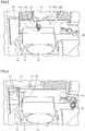
- Fig. 1 is a schematic diagram for illustrating external appearance and internal structure of a machine tool 1 for manufacturing a composite member.
- machine tool 1 includes an operating system 11, a splash guard 12, a spindle head 13, a spindle 14, a rotation apparatus 18, a door 19, and a table apparatus 20.
- Table apparatus 20 has a rotation table 16 and a mount 17 configured to rotatably support rotation table 16.
- Table apparatus 20 is attached to rotation apparatus 18.
- mount 17 is fixed to the central portion of rotation apparatus 18.
- Operating system 11 is a numerical control device serving as a conventional operating panel. Operating system 11 controls an overall operation of machine tool 1 by executing a program or the like designed by a user. For example, operating system 11 controls operations of spindle head 13, spindle 14, rotation apparatus 18, door 19, table apparatus 20, and an additive manufacturing apparatus 30 described later. It should be noted that operating system 11 is a well-known system and is therefore not described herein in detail.
- Spindle head 13 is attached to a cross rail (not shown).
- Spindle head 13 is provided to slidably move in an axial direction represented by an arrow 901 (X-axis direction) and an axial direction represented by an arrow 902 (Y-axis direction).
- Spindle 14 is attached to spindle head 13.
- Spindle 14 is provided to slidably move in an axial direction represented by an arrow 903 (Z-axis direction).
- Spindle 14 has a tip provided with a structure to which a tool holder having a tool attached thereon can be installed.
- the tool holder examples include: additive manufacturing apparatus 30 ( Fig. 2 ) configured to perform additive manufacturing; and a tool holder stored in a tool magazine (not shown) (for example, a tool holder 40 ( Fig. 3 ) including an end mill). It should be noted that a tool holder other than additive manufacturing apparatus 30 is attached to spindle 14 by an automatic tool changer 21 ( Fig. 3 ).
- machining area refers to a space (internal space of machine tool 1) which is partitioned by splash guard 12 and door 19 and in which spindle head 13, spindle 14, rotation apparatus 18, table apparatus 20, additive manufacturing apparatus 30, a workpiece, and the like are movably placed.
- spindle head 13 and spindle 14 are appropriately provided with a feed structure, a guidance structure, a servo motor, and the like to enable the slide movement thereof.
- respective slide movements of spindle head 13 and spindle 14 can be combined to freely change the position of the tool attached to the tool holder in the XYZ space.
- Rotation apparatus 18 is provided to be rotatable through motor driving with respect to a center axis extending in the X-axis direction. Rotation of rotation apparatus 18 causes table apparatus 20 to rotate clockwisely and counterclockwisely (direction represented by an arrow 904) with respect to the center axis.
- rotation table 16 of table apparatus 20 is provided to be rotatable through motor driving with respect to the center axis extending in the vertical (Z-axis) direction. It should be noted that since rotation table 16 is rotated in the direction of arrow 904 by rotation apparatus 18, the center axis of rotation of rotation table 16 is changed while the center axis maintains to be in parallel with the YZ plane.
- rotation table 16 On rotation table 16, a workpiece is held using a chuck or various types of jigs. During cutting with a stationary tool, rotation table 16 is rotated to cause the workpiece to rotate clockwisely and counterclockwisely (direction of arrow 905) with respect to the center axis.
- machine tool 1 is capable of changing a posture of a member, such as a workpiece, placed in the machining area.
- Fig. 2 shows a state in which additive manufacturing apparatus 30 is attached to spindle 14.
- additive manufacturing apparatus 30 includes an application unit 310, an attachment unit 320, and a hose unit 330.
- Attachment unit 320 is a member for fixing additive manufacturing apparatus 30 to spindle 14.
- Hose unit 330 is a supply path of the powders or the like. Hose unit 330 is provided to supply the powders or the like from an apparatus (not shown) having the powders or the like stored therein to application unit 310 via attachment unit 320.
- machine tool 1 stores additive manufacturing apparatus 30 in a holder 39 for the additive manufacturing apparatus.
- holder 39 is configured to be rotatable while maintaining to be in parallel with the XY plane. That is, holder 39 is rotated with respect to an axis parallel to the Z axis.
- Fig. 3 shows a state in which tool holder 40 is attached to spindle 14.
- operating system 11 performs control to open door 19, and then causes the automatic tool changer to attach tool holder 40 to spindle 14. It should be noted that tool holder 40 is exchanged in a state in which additive manufacturing apparatus 30 is stored in holder 39.
- Fig. 4 illustrates a principle of additive manufacturing performed by additive manufacturing apparatus 30.
- additive manufacturing apparatus 30 applies, from tip 311 of application unit 310, laser beam 391, metal powders 392, and gas 393 for shield and carrier. Accordingly, a melted point 394 is formed on the surface of workpiece 399, with the result that metal powders 392 are welded thereto.
- a cladding layer 396 is formed on workpiece 399.
- a cladding material 395 is provided on cladding layer 396.
- a metal layer that can be machined is formed on workpiece 399.
- electron beam may be employed instead of laser beam 391.
- a machining process performed by machine tool 1 a specific example of a machining process performed by machine tool 1 will be described.
- the following describes a process for manufacturing the composite member by performing cutting and additive manufacturing.
- a method for manufacturing a tubular body will be exemplified and illustrated below.
- the shape of the composite member to be manufactured is not limited to the tubular shape.
- the material of the composite member to be manufactured is not limited to the below-described example.
- Fig. 5 illustrates a process for obtaining the base member by cutting workpiece 100.
- machine tool 1 starts cutting using tool holder 40 in order to form a predetermined pattern of groove portion 111 in the surface of workpiece 100 having a cylindrical shape and fixed to a fixture 50.
- Workpiece 100 can be composed of a material such as steel, for example.
- the formation of the groove involves rotation of rotation table 16 and movement (for example, movement in the Y-axis direction) of tool holder 40.
- the rotation speed of rotation table 16, the movement speed of tool holder 40, the rotation speed of the end mill of tool holder 40, and the like are determined based on an instruction from operating system 11.
- Fig. 6 shows an external appearance of base member 110 manufactured by cutting workpiece 100.
- base member 110 has a predetermined pattern of groove portion 111 in its surface.
- Fig. 7 shows a state in which additive manufacturing is performed to base member 110.
- machine tool 1 employs additive manufacturing apparatus 30 to perform cladding (3D-printing), to groove portion 111, using a metal different from steel.
- machine tool 1 forms metal layer 120 on the surface of groove portion 111 by applying powders, such as a copper alloy, an aluminum alloy, or a nickel-based superalloy, from tip 311 of additive manufacturing apparatus 30. More specifically, by way of additive manufacturing, machine tool 1 forms metal layer 120 having a thickness to fill groove portion 111. In other words, machine tool 1 fills groove portion 111 with a metal different from the material of base member 110.
- powders such as a copper alloy, an aluminum alloy, or a nickel-based superalloy
- operating system 11 may restrict application of powders 392 from application unit 310 in order to prevent the cladding from being performed twice.
- the program of operating system 11 may be designed in advance to restrict the application at the position of the intersection by determining the position of the intersection (position thereof in the surface of base member 110) based on the program designed by the user.
- Fig. 8 shows an external appearance of an intermediate member 200 obtained by performing additive manufacturing to base member 110.
- intermediate member 200 is a composite member having base member 110 and metal layer 120.
- Metal layer 120 has the same pattern as the pattern of groove portion 111 formed by cutting.
- machine tool 1 machines a surface of intermediate member 200. Specifically, machine tool 1 machines at least a surface of metal layer 120. It should be noted that machine tool 1 may also machine a surface of base member 110 as with metal layer 120.
- Fig. 9 shows an external appearance of intermediate member 200 after machining the surface of intermediate member 200.
- the surface machining process provides reduced irregularities in the surface of intermediate member 200 as compared with those in the state of Fig. 8 .
- intermediate member 200 may not be necessarily machined if additive manufacturing is further performed to the surface of intermediate member 200 ( Fig. 10 ).
- intermediate member 200 serving as the composite member is manufactured by the manufacturing method including the step of adding, on the surface of base member 110 (first member) composed of the first material (for example, steel), the second material (such as a copper alloy, an aluminum alloy, or a nickel-based superalloy) different from the first material, using additive manufacturing employing directed energy deposition as an additive manufacturing process.
- the method for manufacturing such a tubular body is performed by placing base member 110 (first member) in the machining area of machine tool 1 configured to perform subtractive machining.
- the composite member is manufactured in the machining area within machine tool 1 and is therefore brought into a state in which it can be promptly machined.
- the method for manufacturing the tubular body further includes the step of manufacturing base member 110 by cutting workpiece 100 using machine tool 1. Accordingly, the manufacturing of base member 110 and the additive manufacturing can be performed in the same apparatus (specifically, machining area of machine tool 1).
- the second material is added to the cut portion of workpiece 100. Accordingly, a portion of workpiece 100 can be replaced with the metal layer composed of the second material.
- Fig. 10 shows a state in which the additive manufacturing is performed to intermediate member 200.
- machine tool 1 uses additive manufacturing apparatus 30 to perform cladding (3D-printing) using steel powders on the outer circumferential surface of intermediate member 200. That is, machine tool 1 forms metal layer 130 composed of steel on the outer circumferential surface of intermediate member 200. It should be noted that the formation of metal layer 130 involves rotation of rotation table 16 and movement of additive manufacturing apparatus 30 (for example, movement in the Y-axis direction).
- Fig. 11 shows an external appearance of a finished product 300 obtained by performing additive manufacturing to intermediate member 200 ( Fig. 9 ) having been through the surface machining process. Specifically, Fig. 11 shows the external appearance of finished product 300 obtained by performing a surface machining process to the outer circumferential surface after performing the additive manufacturing.
- finished product 300 which serves as the composite member, is a composite member having base member 110, metal layer 120, and metal layer 130 serving as an outer layer.
- the method for manufacturing the tubular body further includes the step of manufacturing metal layer 130 (third member) using the additive manufacturing to cover intermediate member 200 after the surface machining process (removing).
- the plurality of metal layers 120, 130 composed of different materials can be formed on the surface of base member 110.
- the nickel-based superalloy has a higher strength than that of steel. Accordingly, due to the existence of metal layer 120, finished product 300 can have a significantly increased strength as compared with that of the tubular body composed of only steel and having the same shape. Thus, in finished product 300, metal layer 120 can be functioned as a reinforcement member. Further, finished product 300 can have a higher vibration damping ratio (i.e., ability of a material to absorb and attenuate vibration energy) than that of the tubular body composed of only steel and having the same shape.
- vibration damping ratio i.e., ability of a material to absorb and attenuate vibration energy
- a difference between the strength of finished product 300 and the strength of the tubular body composed of only steel and having the same shape can be similar to a difference between the strength of a carbon fiber reinforced plastic (CFRP) and the strength of a normal plastic.
- CFRP carbon fiber reinforced plastic
- the nickel-based superalloy has a lower thermal conductivity than that of steel.
- finished product 300 when finished product 300 is required to have a low thermal conductivity, finished product 300 can be a product having a thermal conductivity lower than that of the tubular body composed of only steel and having the same shape.
- the nickel-based superalloy is more expensive than steel. Accordingly, finished product 300 can be manufactured less expensively than a tubular body composed of only the nickel-based superalloy and having the same shape.
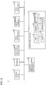
- Fig. 12 shows an overview of the hardware configuration of machine tool 1.
- machine tool 1 includes operating system 11, spindle head 13, spindle 14, rotation apparatus 18, table apparatus 20, automatic tool changer 21, tool magazine 22, and additive manufacturing apparatus 30.
- Operating system 11 has a CPU (Central Processing Unit) 91, a memory 92, a communication IF (InterFace) 93, a display 94, and an operation key 95.
- CPU Central Processing Unit
- memory 92 a memory 92
- communication IF InterFace
- display 94 a display 94
- operation key 95 an operation key
- CPU 91 executes various types of programs stored in memory 92, thereby controlling respective operations of units of machine tool 1 via communication IF 93.
- Display 94 displays various types of information in machine tool 1 such that the user of machine tool 1 can visually recognize the information.
- Operation key 95 receives various inputs (for example, inputs of starting machining) provided by the user.
- Operating system 11 performs a process in accordance with an instruction from the user (process based on a program created by the user), thereby manufacturing finished product 300 of the composite member from workpiece 100 as described based on Fig. 5 to Fig. 11 , for example.
- Fig. 13 is a flowchart showing a flow of the process for manufacturing finished product 300.
- machine tool 1 cuts workpiece 100 to produce base member 110.
- machine tool 1 uses additive manufacturing to add, to base member 110, the material different from the material of base member 110, thereby forming metal layer 120 on the surface of base member 110. Accordingly, intermediate member 200 is produced.
- machine tool 1 cuts the surface of metal layer 120 in intermediate member 200. That is, machine tool 1 performs a surface machining process for removing a portion of metal layer 120. It should be noted that machine tool 1 may not perform step S6 as described above.
- machine tool 1 uses additive manufacturing to manufacture metal layer 130 for covering metal layer 120 thus cut.
- machine tool 1 cuts the surface of metal layer 130. That is, machine tool 1 performs a surface machining process for removing a portion of metal layer 130. Accordingly, finished product 300 is produced.
- Fig. 14 (A) shows a state during cladding (3D printing) performed to groove portion 111 using a metal different from steel.
- Fig. 14 (B) shows a state during cladding performed, using the metal different from steel, to the surface (outer circumferential surface) of base member 110 at an area 112 different from groove portion 111.
- machine tool 1 sets angle of application of laser beam 391 and angle of application of metal powders 392 with respect to area 112 such that these angles differ from angle of application of laser beam 391 and angle of application of metal powders 392 with respect to groove portion 111.
- operating system 11 controls the posture of base member 110 such that in the groove portion (first area) in the surface of base member 110, each of the angle of application of laser beam 391 and angle of application of powders 392 with respect to groove portion 111 becomes a first angle. Moreover, operating system 11 controls the posture of base member 110 such that in area 112 (second area) in the surface of base member 110, each of the respective angles of application of laser beam 391 and powders 392 with respect to area 112 becomes a second angle different from the first angle.
- machine tool 1 the direction of cladding (direction of building up) on the underlying metal can be changed for each area set by the user in advance.
- machine tool 1 can manufacture a composite member having a complicated shape.
Landscapes
- Engineering & Computer Science (AREA)
- Mechanical Engineering (AREA)
- Physics & Mathematics (AREA)
- Optics & Photonics (AREA)
- Manufacturing & Machinery (AREA)
- Chemical & Material Sciences (AREA)
- Materials Engineering (AREA)
- Plasma & Fusion (AREA)
- Composite Materials (AREA)
- Powder Metallurgy (AREA)
- Laser Beam Processing (AREA)
Abstract
Description
- The present invention relates to a composite member configured to include different metals and a method for manufacturing the composite member.
- Conventionally, it has been known to manufacture a composite member through cladding using a metal.
- Japanese Patent Laying-Open No.
10-337618 PTD 1 discloses that a cladding portion formed by melting and cladding copper alloy powders on a valve seat portion in a cylinder head composed of an aluminum-based casting alloy is machined into a predetermined shape by the machining apparatus. - Moreover, as one exemplary method for manufacturing a composite member, Japanese Patent Laying-Open No.
61-183430 PTD 2 discloses a method for manufacturing a screw for injection molding machines, including the steps of: filling a groove of a steel shaft with an alloy material powder mixture including tungsten carbide powders; and sintering the alloy material powder mixture by heating the shaft thus filled with the alloy material powder mixture at a high temperature under a pressure. - Moreover, additive manufacturing has been known conventionally. Additive manufacturing refers to a process of creating an object based on a numerical representation of a three-dimensional shape by adding a material as also described in NPD 1 described below. In many cases, additive manufacturing is implemented by stacking a layer on another layer, and is contrast to subtractive manufacturing. It should be noted that the definition of such additive manufacturing is provided in ASTM F2792-12a (Standard Terminology for Additive Manufacturing Technologies) of ASTM International, which is a private, standards development organization for industrial standards. In addition, additive manufacturing is also referred to as "3D printer".
-
- PTD 1: Japanese Patent Laying-Open No.
10-337618 - PTD 2: Japanese Patent Laying-Open No.
61-183430 - NPD 1: Japan Patent Office, "Patent application technical trends surveys (Fiscal 2013): 3D printer", [online], March, 2014, [Accessed on September 19, 2014], Internet (URL: http://www.jpo.go.jp/shiryou/pdf/gidou-houkoku/25_3dprinter.pdf)
- The cladding in
PTD 1 is just a technique of adding, on a surface of an underlying member (i.e., substrate), a material having a property different from the substrate, and does not have a process of creating an object based on a numerical representation of a three-dimensional shape. Hence, the cladding inPTD 1 does not employ additive manufacturing. - Moreover, the machining apparatus of
PTD 1, which serves as a machine tool configured to perform subtractive machining, is an apparatus for machining the composite member obtained through the cladding, and does not have a function to perform cladding. Hence, the cladding is performed by an apparatus other than the machining apparatus. Accordingly, in order to machine a composite member obtained through cladding, the user has to move the composite member and place the composite member in a predetermined position within the machining apparatus. - In the manufacturing method of
PTD 2, the composite member is obtained through sintering rather than additive manufacturing, and therefore has the following disadvantage. That is, the groove is likely to be insufficiently filled with the alloy material powder mixture at its angled portion (corner portion), with the result that air bubbles are highly likely to be formed in the connected portion. This leads to decreased connection strength and decreased thermal conductivity at the connected portion, disadvantageously. - The invention of the present application has been made in view of the above problem, and has an object to obtain a composite member that is manufactured through additive manufacturing and that is in a state in which the composite member can be promptly machined.
- A composite member according to the present invention is manufactured by a manufacturing method including the step of adding, on a surface of a first member composed of a first material, a second material different from the first material, using additive manufacturing employing directed energy deposition as an additive manufacturing process. The manufacturing method is performed by placing the first member in a machining area of a machine tool configured to perform subtractive machining.
- Preferably, the manufacturing method further includes the step of removing a portion of a second member composed of the added second material.
- Preferably, the manufacturing method further includes the step of manufacturing a third member using the additive manufacturing to cover the second member after the removing.
- Preferably, the manufacturing method further includes the step of manufacturing the first member by cutting a workpiece using the machine tool.
- Preferably, in the step of adding the second material, the second material is added to a cut portion of the workpiece.
- Preferably, the manufacturing method further includes the step of manufacturing the first member by the additive manufacturing.
- Preferably, the directed energy deposition employs laser or electron beam. The machine tool is capable of changing a posture of the first member placed in the machining area. The manufacturing method controls the posture of the first member such that an angle of application of the laser or the electron beam with respect to a first area in the surface of the first member becomes a first angle in the first area. The manufacturing method controls the posture of the first member such that an angle of application of the laser or the electron beam with respect to a second area in the surface of the first member becomes a second angle in the second area.
- Preferably, the second material has a thermal conductivity higher than a thermal conductivity of the first material.
- Preferably, the second material has a strength stronger than a strength of the first material.
- According to another aspect of the present invention, a method for manufacturing a composite member includes the step of adding, on a surface of a member composed of a first material, a second material different from the first material, using additive manufacturing employing directed energy deposition as an additive manufacturing process. The step is performed by placing the first member in a machining area of a machine tool configured to perform subtractive machining.
- According to the present invention, a composite member can be promptly obtained that is manufactured through additive manufacturing and that is in a state in which the composite member can be promptly machined.
-
-
Fig. 1 is a schematic diagram for illustrating external appearance and internal structure of amachine tool 1 for manufacturing a composite member. -
Fig. 2 shows a state in which anadditive manufacturing apparatus 30 is attached to aspindle 14. -
Fig. 3 shows a state in which atool holder 40 is attached tospindle 14. -
Fig. 4 illustrates a principle of additive manufacturing performed byadditive manufacturing apparatus 30. -
Fig. 5 illustrates a process for obtaining a base member by cutting aworkpiece 100. -
Fig. 6 shows an external appearance ofbase member 110 manufactured by cuttingworkpiece 100. -
Fig. 7 shows a state in which additive manufacturing is performed tobase member 110. -
Fig. 8 shows an external appearance of anintermediate member 200 obtained by performing additive manufacturing tobase member 110. -
Fig. 9 shows an external appearance ofintermediate member 200 after machining the surface ofintermediate member 200. -
Fig. 10 shows a state in which additive manufacturing is performed tointermediate member 200. -
Fig. 11 shows an external appearance of a finishedproduct 300 obtained by performing additive manufacturing tointermediate member 200 having been through the surface machining process. -
Fig. 12 shows an overview of a hardware configuration ofmachine tool 1. -
Fig. 13 is a flowchart showing a flow of a process for manufacturing finishedproduct 300. -
Fig. 14 illustrates a configuration in which a direction of applying metal powders upon performing additive manufacturing is changed for each area to which the metal powders are applied. - With reference to figures, the following describes a composite member and a machine tool configured to manufacture the composite member according to an embodiment of the present invention. In the description below, the same reference characters are given to the same parts. Their names and functions are also the same. Hence, they are not described in detail repeatedly.
- Moreover, in the description below, a 5-axis machine having a function of additive manufacturing (i.e., 3D printer) will be illustrated as one example of the above-described machine tool. However, the machine tool is not limited to the 5-axis machine. The machine tool may be any subtractive machine (for example, 4-axis machine) having the function of additive manufacturing. Furthermore, in the description below, it is assumed that directed energy deposition is used as an additive manufacturing process in additive manufacturing.
-
Fig. 1 is a schematic diagram for illustrating external appearance and internal structure of amachine tool 1 for manufacturing a composite member. With reference toFig. 1 ,machine tool 1 includes anoperating system 11, asplash guard 12, aspindle head 13, aspindle 14, arotation apparatus 18, adoor 19, and atable apparatus 20. -
Table apparatus 20 has a rotation table 16 and amount 17 configured to rotatably support rotation table 16.Table apparatus 20 is attached torotation apparatus 18. Specifically, mount 17 is fixed to the central portion ofrotation apparatus 18. -
Operating system 11 is a numerical control device serving as a conventional operating panel.Operating system 11 controls an overall operation ofmachine tool 1 by executing a program or the like designed by a user. For example,operating system 11 controls operations ofspindle head 13,spindle 14,rotation apparatus 18,door 19,table apparatus 20, and anadditive manufacturing apparatus 30 described later. It should be noted thatoperating system 11 is a well-known system and is therefore not described herein in detail. -
Spindle head 13 is attached to a cross rail (not shown).Spindle head 13 is provided to slidably move in an axial direction represented by an arrow 901 (X-axis direction) and an axial direction represented by an arrow 902 (Y-axis direction).Spindle 14 is attached tospindle head 13. -
Spindle 14 is provided to slidably move in an axial direction represented by an arrow 903 (Z-axis direction).Spindle 14 has a tip provided with a structure to which a tool holder having a tool attached thereon can be installed. - Examples of the tool holder include: additive manufacturing apparatus 30 (
Fig. 2 ) configured to perform additive manufacturing; and a tool holder stored in a tool magazine (not shown) (for example, a tool holder 40 (Fig. 3 ) including an end mill). It should be noted that a tool holder other thanadditive manufacturing apparatus 30 is attached to spindle 14 by an automatic tool changer 21 (Fig. 3 ). - The tool magazine is disposed opposite to a machining area relative to door 19 (i.e., disposed behind
door 19 inFig. 1 ). It should be noted that the term "machining area" refers to a space (internal space of machine tool 1) which is partitioned bysplash guard 12 anddoor 19 and in which spindlehead 13,spindle 14,rotation apparatus 18,table apparatus 20,additive manufacturing apparatus 30, a workpiece, and the like are movably placed. - Each of
spindle head 13 andspindle 14 is appropriately provided with a feed structure, a guidance structure, a servo motor, and the like to enable the slide movement thereof. Inmachine tool 1, respective slide movements ofspindle head 13 andspindle 14 can be combined to freely change the position of the tool attached to the tool holder in the XYZ space. -
Rotation apparatus 18 is provided to be rotatable through motor driving with respect to a center axis extending in the X-axis direction. Rotation ofrotation apparatus 18 causestable apparatus 20 to rotate clockwisely and counterclockwisely (direction represented by an arrow 904) with respect to the center axis. - In a default state as shown in
Fig. 1 , rotation table 16 oftable apparatus 20 is provided to be rotatable through motor driving with respect to the center axis extending in the vertical (Z-axis) direction. It should be noted that since rotation table 16 is rotated in the direction ofarrow 904 byrotation apparatus 18, the center axis of rotation of rotation table 16 is changed while the center axis maintains to be in parallel with the YZ plane. - On rotation table 16, a workpiece is held using a chuck or various types of jigs. During cutting with a stationary tool, rotation table 16 is rotated to cause the workpiece to rotate clockwisely and counterclockwisely (direction of arrow 905) with respect to the center axis.
- With the configuration described above,
machine tool 1 is capable of changing a posture of a member, such as a workpiece, placed in the machining area. -
Fig. 2 shows a state in whichadditive manufacturing apparatus 30 is attached tospindle 14. With reference toFig. 2 ,additive manufacturing apparatus 30 includes anapplication unit 310, anattachment unit 320, and ahose unit 330. - Although details will be described later, metal powders or the like are applied from
tip 311 ofapplication unit 310.Attachment unit 320 is a member for fixingadditive manufacturing apparatus 30 tospindle 14.Hose unit 330 is a supply path of the powders or the like.Hose unit 330 is provided to supply the powders or the like from an apparatus (not shown) having the powders or the like stored therein toapplication unit 310 viaattachment unit 320. - When
additive manufacturing apparatus 30 is not used,machine tool 1 storesadditive manufacturing apparatus 30 in aholder 39 for the additive manufacturing apparatus. It should be noted thatholder 39 is configured to be rotatable while maintaining to be in parallel with the XY plane. That is,holder 39 is rotated with respect to an axis parallel to the Z axis. -
Fig. 3 shows a state in whichtool holder 40 is attached tospindle 14. With reference toFig. 3 ,operating system 11 performs control to opendoor 19, and then causes the automatic tool changer to attachtool holder 40 tospindle 14. It should be noted thattool holder 40 is exchanged in a state in whichadditive manufacturing apparatus 30 is stored inholder 39. -
Fig. 4 illustrates a principle of additive manufacturing performed byadditive manufacturing apparatus 30. With reference toFig. 4 , while moving in a predetermined direction (the direction of arrow),additive manufacturing apparatus 30 applies, fromtip 311 ofapplication unit 310,laser beam 391,metal powders 392, andgas 393 for shield and carrier. Accordingly, a meltedpoint 394 is formed on the surface ofworkpiece 399, with the result that metal powders 392 are welded thereto. - Specifically, a
cladding layer 396 is formed onworkpiece 399. Acladding material 395 is provided oncladding layer 396. When claddingmaterial 395 is cooled, a metal layer that can be machined is formed onworkpiece 399. It should be noted that electron beam may be employed instead oflaser beam 391. - Hereinafter, a specific example of a machining process performed by
machine tool 1 will be described. Specifically, as one exemplary machining process performed bymachine tool 1, the following describes a process for manufacturing the composite member by performing cutting and additive manufacturing. Particularly, a method for manufacturing a tubular body will be exemplified and illustrated below. It should be noted that the shape of the composite member to be manufactured is not limited to the tubular shape. Moreover, the material of the composite member to be manufactured is not limited to the below-described example. -
Fig. 5 illustrates a process for obtaining the base member by cuttingworkpiece 100. With reference toFig. 5 ,machine tool 1 starts cutting usingtool holder 40 in order to form a predetermined pattern ofgroove portion 111 in the surface ofworkpiece 100 having a cylindrical shape and fixed to afixture 50.Workpiece 100 can be composed of a material such as steel, for example. - It should be noted that the formation of the groove involves rotation of rotation table 16 and movement (for example, movement in the Y-axis direction) of
tool holder 40. Moreover, the rotation speed of rotation table 16, the movement speed oftool holder 40, the rotation speed of the end mill oftool holder 40, and the like are determined based on an instruction fromoperating system 11. -
Fig. 6 shows an external appearance ofbase member 110 manufactured by cuttingworkpiece 100. With reference toFig. 6 ,base member 110 has a predetermined pattern ofgroove portion 111 in its surface. -
Fig. 7 shows a state in which additive manufacturing is performed tobase member 110. With reference toFig. 7 ,machine tool 1 employsadditive manufacturing apparatus 30 to perform cladding (3D-printing), to grooveportion 111, using a metal different from steel. - Specifically,
machine tool 1forms metal layer 120 on the surface ofgroove portion 111 by applying powders, such as a copper alloy, an aluminum alloy, or a nickel-based superalloy, fromtip 311 ofadditive manufacturing apparatus 30. More specifically, by way of additive manufacturing,machine tool 1forms metal layer 120 having a thickness to fillgroove portion 111. In other words,machine tool 1 fillsgroove portion 111 with a metal different from the material ofbase member 110. - It should be noted that for an intersection of groove in
groove portion 111,operating system 11 may restrict application ofpowders 392 fromapplication unit 310 in order to prevent the cladding from being performed twice. The program ofoperating system 11 may be designed in advance to restrict the application at the position of the intersection by determining the position of the intersection (position thereof in the surface of base member 110) based on the program designed by the user. -
Fig. 8 shows an external appearance of anintermediate member 200 obtained by performing additive manufacturing tobase member 110. With reference toFig. 8 ,intermediate member 200 is a composite member havingbase member 110 andmetal layer 120.Metal layer 120 has the same pattern as the pattern ofgroove portion 111 formed by cutting. - The following describes a step of removing a portion of metal layer 120 (second member) added (welded) by additive manufacturing and composed of the second material. After
intermediate member 200 ofFig. 8 is obtained,machine tool 1 machines a surface ofintermediate member 200. Specifically,machine tool 1 machines at least a surface ofmetal layer 120. It should be noted thatmachine tool 1 may also machine a surface ofbase member 110 as withmetal layer 120. -
Fig. 9 shows an external appearance ofintermediate member 200 after machining the surface ofintermediate member 200. With reference toFig. 9 , the surface machining process provides reduced irregularities in the surface ofintermediate member 200 as compared with those in the state ofFig. 8 . - It should be noted that as described below, the surface of
intermediate member 200 may not be necessarily machined if additive manufacturing is further performed to the surface of intermediate member 200 (Fig. 10 ). - As described above,
intermediate member 200 serving as the composite member is manufactured by the manufacturing method including the step of adding, on the surface of base member 110 (first member) composed of the first material (for example, steel), the second material (such as a copper alloy, an aluminum alloy, or a nickel-based superalloy) different from the first material, using additive manufacturing employing directed energy deposition as an additive manufacturing process. Moreover, the method for manufacturing such a tubular body is performed by placing base member 110 (first member) in the machining area ofmachine tool 1 configured to perform subtractive machining. The composite member is manufactured in the machining area withinmachine tool 1 and is therefore brought into a state in which it can be promptly machined. - Moreover, the method for manufacturing the tubular body further includes the step of
manufacturing base member 110 by cuttingworkpiece 100 usingmachine tool 1. Accordingly, the manufacturing ofbase member 110 and the additive manufacturing can be performed in the same apparatus (specifically, machining area of machine tool 1). - Moreover, in the step of adding the second material to
base member 110, the second material is added to the cut portion ofworkpiece 100. Accordingly, a portion ofworkpiece 100 can be replaced with the metal layer composed of the second material. -
Fig. 10 shows a state in which the additive manufacturing is performed tointermediate member 200. With reference toFig. 10 ,machine tool 1 usesadditive manufacturing apparatus 30 to perform cladding (3D-printing) using steel powders on the outer circumferential surface ofintermediate member 200. That is,machine tool 1forms metal layer 130 composed of steel on the outer circumferential surface ofintermediate member 200. It should be noted that the formation ofmetal layer 130 involves rotation of rotation table 16 and movement of additive manufacturing apparatus 30 (for example, movement in the Y-axis direction). -
Fig. 11 shows an external appearance of afinished product 300 obtained by performing additive manufacturing to intermediate member 200 (Fig. 9 ) having been through the surface machining process. Specifically,Fig. 11 shows the external appearance offinished product 300 obtained by performing a surface machining process to the outer circumferential surface after performing the additive manufacturing. With reference toFig. 11 ,finished product 300, which serves as the composite member, is a composite member havingbase member 110,metal layer 120, andmetal layer 130 serving as an outer layer. - As described above, the method for manufacturing the tubular body further includes the step of manufacturing metal layer 130 (third member) using the additive manufacturing to cover
intermediate member 200 after the surface machining process (removing). According to the configuration, the plurality ofmetal layers base member 110. -
- (1) The following describes an advantage when the material of each of
base member 110 andmetal layer 130 is steel and the material ofmetal layer 120 is a copper alloy.
The copper alloy is inferior to steel in terms of strength but has a higher thermal conductivity. Hence, due to existence ofmetal layer 120,finished product 300 can have an increased thermal conductivity as compared with that of a tubular body composed of only steel and having the same shape. Moreover, sinceonly metal layer 120 is composed of the copper alloy,finished product 300 has a strength comparable to that of the tubular body composed of only steel and having the same shape.
Particularly,metal layer 120 exists betweenbase member 110 andmetal layer 130, so thatmetal layer 120 inferior tobase member 110 andmetal layer 130 in strength is not exposed to outside apart from both the ends offinished product 300. Hence, even if a certain external force is exerted on the surface offinished product 300,finished product 300 is less likely to be scratched as compared with a case where the metal layer composed of the copper alloy is exposed. Furthermore, sincemetal layer 120 composed of the copper alloy is not exposed, a heat retaining property is more excellent than that in the case wheremetal layer 120 composed of the copper alloy is exposed.
It should be noted that also when the material ofmetal layer 120 is composed of an aluminum alloy, the same advantage is attained as that in the case where the material ofmetal layer 120 is the copper alloy. - (2) Next, the following describes an advantage when the material of each of
base member 110 andmetal layer 130 is steel and the material ofmetal layer 120 is a nickel-based superalloy. - The nickel-based superalloy has a higher strength than that of steel. Accordingly, due to the existence of
metal layer 120,finished product 300 can have a significantly increased strength as compared with that of the tubular body composed of only steel and having the same shape. Thus, infinished product 300,metal layer 120 can be functioned as a reinforcement member. Further,finished product 300 can have a higher vibration damping ratio (i.e., ability of a material to absorb and attenuate vibration energy) than that of the tubular body composed of only steel and having the same shape. It should be noted that figuratively speaking, a difference between the strength offinished product 300 and the strength of the tubular body composed of only steel and having the same shape can be similar to a difference between the strength of a carbon fiber reinforced plastic (CFRP) and the strength of a normal plastic. - Moreover, the nickel-based superalloy has a lower thermal conductivity than that of steel. Hence, when
finished product 300 is required to have a low thermal conductivity,finished product 300 can be a product having a thermal conductivity lower than that of the tubular body composed of only steel and having the same shape. - Moreover, the nickel-based superalloy is more expensive than steel. Accordingly,
finished product 300 can be manufactured less expensively than a tubular body composed of only the nickel-based superalloy and having the same shape. -
Fig. 12 shows an overview of the hardware configuration ofmachine tool 1. With reference toFig. 12 ,machine tool 1 includesoperating system 11,spindle head 13,spindle 14,rotation apparatus 18,table apparatus 20,automatic tool changer 21,tool magazine 22, andadditive manufacturing apparatus 30. -
Operating system 11 has a CPU (Central Processing Unit) 91, amemory 92, a communication IF (InterFace) 93, adisplay 94, and anoperation key 95. -
CPU 91 executes various types of programs stored inmemory 92, thereby controlling respective operations of units ofmachine tool 1 via communication IF 93.Display 94 displays various types of information inmachine tool 1 such that the user ofmachine tool 1 can visually recognize the information.Operation key 95 receives various inputs (for example, inputs of starting machining) provided by the user. -
Operating system 11 performs a process in accordance with an instruction from the user (process based on a program created by the user), thereby manufacturingfinished product 300 of the composite member fromworkpiece 100 as described based onFig. 5 to Fig. 11 , for example. -
Fig. 13 is a flowchart showing a flow of the process for manufacturingfinished product 300. With reference toFig. 13 , in a step S2,machine tool 1 cuts workpiece 100 to producebase member 110. In a step S4,machine tool 1 uses additive manufacturing to add, tobase member 110, the material different from the material ofbase member 110, thereby formingmetal layer 120 on the surface ofbase member 110. Accordingly,intermediate member 200 is produced. - In a step S6,
machine tool 1 cuts the surface ofmetal layer 120 inintermediate member 200. That is,machine tool 1 performs a surface machining process for removing a portion ofmetal layer 120. It should be noted thatmachine tool 1 may not perform step S6 as described above. - In a step S8,
machine tool 1 uses additive manufacturing to manufacturemetal layer 130 for coveringmetal layer 120 thus cut. In a step S10,machine tool 1 cuts the surface ofmetal layer 130. That is,machine tool 1 performs a surface machining process for removing a portion ofmetal layer 130. Accordingly,finished product 300 is produced. -
- (1) The description above is directed to the method for producing the base member by cutting
workpiece 100 using the tool; however, it is not limited to this. For example,base member 110 may be manufactured using additive manufacturing. In other words,base member 110 may be manufactured by performing cladding to a workpiece (not shown). - (2) The description above is directed to the configuration (
Fig. 4 ) in whichapplication unit 310 has one application opening forpowders 392; however, it is not limited to this.Additive manufacturing apparatus 30 may be configured to have two or more application openings from which powders of different metals can be applied respectively, for example. - (3) In the description above,
metal layer 130 composed of steel is created by usingadditive manufacturing apparatus 30 to perform the cladding to the outer circumferential surface ofintermediate member 200 using the powders of the same material (i.e., steel) as that ofbase member 110. However, it is not limited to this.Metal layer 130 serving as an outer layer may be formed using a metal different from steel and the material of the powders used for the formation ofmetal layer 120. - (4) The description above is directed to the example in which the surface machining process is performed to
metal layers metal layers machine tool 1. - (5) The method for manufacturing the composite member may be configured as follows.
Fig. 14 illustrates a configuration in which the direction of applying the metal powders upon performing additive manufacturing is changed for each area to which the metal powders are applied. - As with
Fig. 7 ,Fig. 14 (A) shows a state during cladding (3D printing) performed to grooveportion 111 using a metal different from steel.Fig. 14 (B) shows a state during cladding performed, using the metal different from steel, to the surface (outer circumferential surface) ofbase member 110 at anarea 112 different fromgroove portion 111. - With reference to
Figs. 14 (A) and (B) ,machine tool 1 sets angle of application oflaser beam 391 and angle of application ofmetal powders 392 with respect toarea 112 such that these angles differ from angle of application oflaser beam 391 and angle of application ofmetal powders 392 with respect togroove portion 111. - That is,
operating system 11 controls the posture ofbase member 110 such that in the groove portion (first area) in the surface ofbase member 110, each of the angle of application oflaser beam 391 and angle of application ofpowders 392 with respect togroove portion 111 becomes a first angle. Moreover,operating system 11 controls the posture ofbase member 110 such that in area 112 (second area) in the surface ofbase member 110, each of the respective angles of application oflaser beam 391 andpowders 392 with respect toarea 112 becomes a second angle different from the first angle. - Thus, according to
machine tool 1, the direction of cladding (direction of building up) on the underlying metal can be changed for each area set by the user in advance. Hence, as compared with a configuration in which the direction of cladding cannot be changed for each area,machine tool 1 can manufacture a composite member having a complicated shape. - The embodiments disclosed herein are illustrative and are not limited to only the content above. The scope of the present invention is defined by the terms of the claims, and is intended to include any modifications within the scope and meaning equivalent to the terms of the claims.
-
- 1: machine tool; 11: operating system; 12: splash guard; 13: spindle head; 14: spindle; 16: rotation table; 17: mount; 18: rotation apparatus; 19: door; 20: table apparatus; 21: automatic tool changer; 22: tool magazine; 30: additive manufacturing apparatus; 39: holder; 40: tool holder; 50: fixture; 91: CPU; 92: memory; 100, 399: workpiece; 110: base member; 111: groove portion; 112: area; 120, 130: metal layer; 200: intermediate member; 300: finished product; 310: application unit; 311: tip; 320: attachment unit; 330: hose unit; 391: laser beam; 392: powder; 393: gas; 395: cladding material; 396: cladding layer.
Claims (10)
- A composite member manufactured by a manufacturing method including the step of adding, on a surface of a first member composed of a first material, a second material different from the first material, using additive manufacturing employing directed energy deposition as an additive manufacturing process,
the manufacturing method being performed by placing the first member in a machining area of a machine tool configured to perform subtractive machining. - The composite member according to claim 1, wherein the manufacturing method further includes the step of removing a portion of a second member composed of the added second material.
- The composite member according to claim 2, wherein the manufacturing method further includes the step of manufacturing a third member using the additive manufacturing to cover the second member after the removing.
- The composite member according to any one of claims 1 to 3, wherein the manufacturing method further includes the step of manufacturing the first member by cutting a workpiece using the machine tool.
- The composite member according to claim 4, wherein in the step of adding the second material, the second material is added to a cut portion of the workpiece.
- The composite member according to any one of claims 1 to 3, wherein the manufacturing method further includes the step of manufacturing the first member by the additive manufacturing.
- The composite member according to any one of claims 1 to 5, wherein
the directed energy deposition employs laser or electron beam, and
the machine tool is capable of changing a posture of the first member placed in the machining area, and
the manufacturing method includes the steps of:controlling the posture of the first member such that an angle of application of the laser or the electron beam with respect to a first area in the surface of the first member becomes a first angle in the first area; andcontrolling the posture of the first member such that an angle of application of the laser or the electron beam with respect to a second area in the surface of the first member becomes a second angle in the second area. - The composite member according to any one of claims 1 to 7, wherein the second material has a thermal conductivity higher than a thermal conductivity of the first material.
- The composite member according to any one of claims 1 to 7, wherein the second material has a strength stronger than a strength of the first material.
- A method for manufacturing a composite member, comprising the step of adding, on a surface of a member composed of a first material, a second material different from the first material, using additive manufacturing employing directed energy deposition as an additive manufacturing process,
the step being performed by placing the first member in a machining area of a machine tool configured to perform subtractive machining.
Applications Claiming Priority (2)
| Application Number | Priority Date | Filing Date | Title |
|---|---|---|---|
| JP2014214685A JP5878604B1 (en) | 2014-10-21 | 2014-10-21 | Manufacturing method of composite material |
| PCT/JP2015/069795 WO2016063584A1 (en) | 2014-10-21 | 2015-07-09 | Composite material and composite material manufacturing method |
Publications (4)
| Publication Number | Publication Date |
|---|---|
| EP3210716A1 true EP3210716A1 (en) | 2017-08-30 |
| EP3210716A4 EP3210716A4 (en) | 2018-07-04 |
| EP3210716B1 EP3210716B1 (en) | 2023-06-14 |
| EP3210716C0 EP3210716C0 (en) | 2023-06-14 |
Family
ID=55440599
Family Applications (1)
| Application Number | Title | Priority Date | Filing Date |
|---|---|---|---|
| EP15853007.1A Active EP3210716B1 (en) | 2014-10-21 | 2015-07-09 | Method for manufacturing a composite member |
Country Status (5)
| Country | Link |
|---|---|
| US (1) | US11534857B2 (en) |
| EP (1) | EP3210716B1 (en) |
| JP (1) | JP5878604B1 (en) |
| CN (1) | CN106794561B (en) |
| WO (1) | WO2016063584A1 (en) |
Families Citing this family (38)
| Publication number | Priority date | Publication date | Assignee | Title |
|---|---|---|---|---|
| TWI535554B (en) * | 2014-01-06 | 2016-06-01 | 財團法人工業技術研究院 | Three-dimensional molded product and manufacturing apparatus and manufacturing method of three-dimensional molded product |
| US20170129180A1 (en) * | 2014-06-09 | 2017-05-11 | Hybrid Manufacturing Technologies Limited | Material processing methods and related apparatus |
| JP5937713B1 (en) * | 2015-03-20 | 2016-06-22 | Dmg森精機株式会社 | Processing machine |
| US11465357B2 (en) * | 2015-03-24 | 2022-10-11 | The Johns Hopkins University | Systems and methods for conformal additive manufacturing |
| US20190184496A1 (en) | 2016-08-30 | 2019-06-20 | Weir Group Ip Limited | Forming a rotary part |
| US20180071819A1 (en) | 2016-09-15 | 2018-03-15 | NanoCore Technologies, Inc. | System and method for additive metal manufacturing |
| WO2018054902A1 (en) * | 2016-09-20 | 2018-03-29 | Autotech Engineering Aie | Reinforcing structural components |
| US11219976B2 (en) * | 2016-09-29 | 2022-01-11 | Gkn Aerospace Newington Llc | Manufacturing method for cylindrical parts |
| JP6388238B2 (en) * | 2016-11-22 | 2018-09-12 | フドー株式会社 | Manufacturing method of fiber reinforced plastic products |
| CN108340161A (en) * | 2017-01-24 | 2018-07-31 | 昆山快成三维科技有限公司 | A kind of 3D printing nozzle support device towards wire fused glass pellet with brill milling compounding machine bed |
| WO2018154719A1 (en) * | 2017-02-24 | 2018-08-30 | 三菱重工コンプレッサ株式会社 | Laminate shaping method and laminate shaping device |
| JP6751040B2 (en) * | 2017-03-13 | 2020-09-02 | 株式会社神戸製鋼所 | Manufacturing method, manufacturing system, and manufacturing program for layered product |
| US11123819B2 (en) * | 2017-09-25 | 2021-09-21 | Hamilton Sundstrand Corporation | Additive manufacturing method |
| US11229953B2 (en) | 2017-11-29 | 2022-01-25 | Lincoln Global, Inc. | Methods and systems for additive manufacturing |
| CN108115930A (en) * | 2018-01-16 | 2018-06-05 | 宁夏共享机床辅机有限公司 | A kind of 3D printer protective cover based on FDM |
| CN108311703B (en) * | 2018-02-01 | 2023-02-28 | 深圳市铭利达精密技术股份有限公司 | Forming method of high-performance light precise structural part of new energy automobile |
| US10520923B2 (en) | 2018-05-22 | 2019-12-31 | Mantle Inc. | Method and system for automated toolpath generation |
| JP7084224B2 (en) | 2018-06-20 | 2022-06-14 | コマツNtc株式会社 | 3D modeling device and 3D modeling method |
| US11426818B2 (en) | 2018-08-10 | 2022-08-30 | The Research Foundation for the State University | Additive manufacturing processes and additively manufactured products |
| JP6511577B1 (en) | 2018-08-21 | 2019-05-15 | 独立行政法人国立高等専門学校機構 | Molding apparatus and molding method |
| EP3946780A4 (en) * | 2019-04-01 | 2022-12-28 | Stinger Advanced Manufacturing Corporation | SYSTEMS AND METHODS FOR DISCONTINUOUS COMPONENT DEPOSIT |
| US20220214121A1 (en) * | 2019-04-04 | 2022-07-07 | Titomic Limited | Multi-material device for heat transfer and a method of manufacture |
| JP6948431B2 (en) * | 2019-04-09 | 2021-10-13 | 株式会社ExtraBold | Machine tool equipment and its control method |
| JP7309544B2 (en) * | 2019-09-13 | 2023-07-18 | 株式会社東芝 | Coating method and coating structure |
| EP4070937B1 (en) | 2019-12-03 | 2024-07-17 | Mitsubishi Gas Chemical Company, Inc. | Method for producing fiber-reinforced resin article |
| CN111097908A (en) * | 2020-01-02 | 2020-05-05 | 北京机科国创轻量化科学研究院有限公司 | A kind of injection molding machine screw and its manufacturing method |
| WO2021171371A1 (en) * | 2020-02-25 | 2021-09-02 | 株式会社ニコン | Processing system |
| WO2021248057A1 (en) * | 2020-06-05 | 2021-12-09 | Dc Precision Ceramics, Llc | Manufacturing systems and methods for three-dimensional printing |
| JP6892542B1 (en) * | 2020-08-19 | 2021-06-23 | 株式会社神戸製鋼所 | Manufacturing method of modeled object and modeled object |
| CN112192020B (en) * | 2020-09-28 | 2022-09-09 | 哈尔滨理工大学 | A fixture for machining cross-scale micro-features of ball-end milling cutters |
| CN112024884A (en) * | 2020-10-10 | 2020-12-04 | 浙江意动科技股份有限公司 | A 3D printing equipment for metal powder laser additive manufacturing SLM process |
| DE102021106305A1 (en) * | 2021-03-16 | 2022-09-22 | Karlsruher Institut für Technologie (Körperschaft des öffentlichen Rechts) | Process for manufacturing pipes with topographical internal structures |
| CN113664222B (en) * | 2021-08-23 | 2024-03-26 | 华南理工大学 | Composite laser device and method for directional energy deposition equipment |
| CN121152720A (en) | 2023-04-26 | 2025-12-16 | 三菱瓦斯化学株式会社 | Manufacturing method of fiber-reinforced plastic products |
| US20240425963A1 (en) * | 2023-06-23 | 2024-12-26 | Additive Technologies LLC d/b/a ADDITEC | Bimetallic composite parts and methods thereof |
| IT202300014919A1 (en) * | 2023-07-17 | 2025-01-17 | Ge Avio Srl | COMPLIANT DIRECTED ENERGY DEPOSITION DEVICES AND CREATION TABLE ASSEMBLIES COMPRISING THE SAME. |
| US20250178093A1 (en) * | 2023-11-30 | 2025-06-05 | The Boeing Company | Method and system for additively manufacturing an article, and method for controlling an additive manufacturing process |
| JP7771465B1 (en) * | 2025-06-23 | 2025-11-17 | Dmg森精機株式会社 | Additive processing method, additive processing device, and additive processing program |
Family Cites Families (29)
| Publication number | Priority date | Publication date | Assignee | Title |
|---|---|---|---|---|
| JPH0680163B2 (en) | 1985-02-07 | 1994-10-12 | 株式会社クボタ | Method of manufacturing screw for injection molding machine having excellent wear resistance and corrosion resistance |
| EP0538244B1 (en) * | 1986-10-17 | 1996-05-22 | Board Of Regents, The University Of Texas System | Method and apparatus for producing parts by selective sintering |
| US5207371A (en) * | 1991-07-29 | 1993-05-04 | Prinz Fritz B | Method and apparatus for fabrication of three-dimensional metal articles by weld deposition |
| JPH05271898A (en) * | 1992-02-17 | 1993-10-19 | Ind Technol Res Inst | Surface treatment method of injection screw in injection molding machine |
| US5775402A (en) | 1995-10-31 | 1998-07-07 | Massachusetts Institute Of Technology | Enhancement of thermal properties of tooling made by solid free form fabrication techniques |
| JPH10337618A (en) | 1997-06-05 | 1998-12-22 | Nissan Motor Co Ltd | Processing device and processing method for overlay parts |
| JP3446618B2 (en) | 1998-08-26 | 2003-09-16 | 松下電工株式会社 | Surface finishing method for metal powder sintered parts |
| US6463349B2 (en) * | 2000-03-23 | 2002-10-08 | Solidica, Inc. | Ultrasonic object consolidation system and method |
| US20020147521A1 (en) * | 2001-03-14 | 2002-10-10 | Milling Systems And Concepts Pte Ltd. | Prototype production system and method |
| DE10229952B4 (en) | 2002-07-03 | 2007-08-30 | Cl Schutzrechtsverwaltungs Gmbh | Metallic workpiece and method of making the same |
| JP3599059B2 (en) * | 2003-02-25 | 2004-12-08 | 松下電工株式会社 | Method and apparatus for manufacturing three-dimensional shaped object |
| US7073561B1 (en) * | 2004-11-15 | 2006-07-11 | Henn David S | Solid freeform fabrication system and method |
| CN1814861A (en) * | 2006-03-06 | 2006-08-09 | 江苏大学 | Method for preparing multi-element mixed surface fused coating based on 2-D figure |
| CN101249510A (en) * | 2008-03-27 | 2008-08-27 | 安徽工业大学 | A repaired roll and a method for repairing a roll |
| JP5186306B2 (en) * | 2008-08-25 | 2013-04-17 | パナソニック株式会社 | Manufacturing method of three-dimensional shaped object |
| JP5532629B2 (en) * | 2009-02-27 | 2014-06-25 | 日産自動車株式会社 | Laser cladding valve sheet forming method and laser cladding valve sheet forming apparatus |
| JP2010223013A (en) * | 2009-03-19 | 2010-10-07 | Honda Motor Co Ltd | Cylinder head manufacturing method |
| CN101994114A (en) * | 2009-08-24 | 2011-03-30 | 沈阳大陆激光成套设备有限公司 | Laser cladding wear-resisting and heat fatigue-resisting alloy coating process for manufacturing hot rolled seamless steel tube rolling mill retained mandrel |
| AU2010318559B2 (en) * | 2009-11-13 | 2015-08-20 | Sciaky, Inc. | Electron beam layer manufacturing using scanning electron monitored closed loop control |
| US9103358B2 (en) * | 2010-03-16 | 2015-08-11 | Eaton Corporation | Corrosion-resistant position measurement system and method of forming same |
| CN102094198B (en) * | 2011-03-25 | 2012-05-23 | 天津市汇利通金属表面技术有限公司 | Alloy laser-cladding method for surface of helical casing in screw pump |
| WO2012160811A1 (en) * | 2011-05-23 | 2012-11-29 | パナソニック株式会社 | Method for producing three-dimensional shape structure |
| US9310081B2 (en) * | 2012-05-14 | 2016-04-12 | Delavan Inc. | Methods of fabricating fuel injectors using laser additive deposition |
| ES2896351T3 (en) * | 2012-09-27 | 2022-02-24 | Allomet Corp | Methods for forming a metallic or ceramic article having a novel composition of functionally graded material |
| US9289845B2 (en) * | 2012-11-07 | 2016-03-22 | David S. Henn | Metal deposition of exterior members in oil field tubulars |
| EP2978952A4 (en) * | 2013-03-28 | 2016-03-23 | United Technologies Corp | Gas turbine component manufacturing |
| CN103290407B (en) * | 2013-06-25 | 2016-12-28 | 江苏中科大港激光科技有限公司 | Apparatus and method for for the reciprocal laser melting coating of shaft-like workpiece |
| CN103741135A (en) * | 2013-12-19 | 2014-04-23 | 辽宁金之运激光工程技术有限公司 | Device for remanufacturing metal surface and application method of device |
| CN204185562U (en) * | 2014-09-09 | 2015-03-04 | 重庆江陆激光科技有限公司 | A kind of laser cladding equipment for repairing grinding machine spindle spline |
-
2014
- 2014-10-21 JP JP2014214685A patent/JP5878604B1/en active Active
-
2015
- 2015-07-09 CN CN201580045228.5A patent/CN106794561B/en active Active
- 2015-07-09 US US15/315,566 patent/US11534857B2/en active Active
- 2015-07-09 EP EP15853007.1A patent/EP3210716B1/en active Active
- 2015-07-09 WO PCT/JP2015/069795 patent/WO2016063584A1/en not_active Ceased
Also Published As
| Publication number | Publication date |
|---|---|
| EP3210716A4 (en) | 2018-07-04 |
| EP3210716B1 (en) | 2023-06-14 |
| US11534857B2 (en) | 2022-12-27 |
| WO2016063584A1 (en) | 2016-04-28 |
| EP3210716C0 (en) | 2023-06-14 |
| CN106794561A (en) | 2017-05-31 |
| JP2016078205A (en) | 2016-05-16 |
| JP5878604B1 (en) | 2016-03-08 |
| US20170209958A1 (en) | 2017-07-27 |
| CN106794561B (en) | 2022-05-31 |
Similar Documents
| Publication | Publication Date | Title |
|---|---|---|
| US11534857B2 (en) | Composite member and method for manufacturing composite member | |
| US10889098B2 (en) | Method, data processing device, and machine tool for generating dimensional tool paths and control signals for material dispositioning | |
| US10688581B2 (en) | 3D metal printing device and process | |
| US10635076B1 (en) | Methods for generating numerical control programs for automated manufacturing systems with multiple independent toolheads | |
| JP5940712B1 (en) | Processing machine | |
| CN103890670B (en) | Numerical control device | |
| Rosli et al. | Design and development of a low-cost 3D metal printer | |
| US20100305745A1 (en) | Nc program generating device and nc program generating method | |
| JP2016135911A (en) | Machine tool system and method for additive manufacturing | |
| JP6626788B2 (en) | Control data generation method, information processing device, machine tool, and program | |
| CN105320074B (en) | Numerical control device and control method | |
| JP2009202247A (en) | Machine tool and method of machining internal surface of workpiece by using the machine tool | |
| JP2008188726A (en) | Slide core hole machining method, and measuring and correcting system for use in slide core hole machining | |
| JPWO2010004960A1 (en) | Interference check device, interference check method, and machine tool provided with interference check device | |
| JP2005271148A (en) | Tool path data generation device and control device including the same | |
| Sadasivam et al. | Design and fabrication of micro-plasma transferred wire arc additive manufacturing system | |
| Li et al. | Bending-Additive-Machining hybrid manufacturing of sheet metal structures | |
| CA2913288C (en) | 3d metal printing device and process | |
| Hwang et al. | A study on the development of post processor for five-axis machining using angle head spindle | |
| JP6726280B2 (en) | Mold manufacturing method, non-transitory computer-readable storage medium, and controller | |
| Grzesik et al. | Hybrid additive and subtractive processes | |
| Antonelli et al. | Collaborative Robot for Contouring Machining of 3D-Printed Components | |
| JP7698768B1 (en) | ADDITIONAL PROCESSING APPARATUS, ADDITIONAL PROCESSING METHOD, AND ADDITIONAL PROCESSING PROGRAM | |
| JP7681765B1 (en) | Machining method, machining device, and machining program | |
| Manogaran et al. | Measurement and comparison of force effort during friction stir welding in a parallel kinematic 5-axis milling machine |
Legal Events
| Date | Code | Title | Description |
|---|---|---|---|
| STAA | Information on the status of an ep patent application or granted ep patent |
Free format text: STATUS: THE INTERNATIONAL PUBLICATION HAS BEEN MADE |
|
| PUAI | Public reference made under article 153(3) epc to a published international application that has entered the european phase |
Free format text: ORIGINAL CODE: 0009012 |
|
| STAA | Information on the status of an ep patent application or granted ep patent |
Free format text: STATUS: REQUEST FOR EXAMINATION WAS MADE |
|
| 17P | Request for examination filed |
Effective date: 20170522 |
|
| AK | Designated contracting states |
Kind code of ref document: A1 Designated state(s): AL AT BE BG CH CY CZ DE DK EE ES FI FR GB GR HR HU IE IS IT LI LT LU LV MC MK MT NL NO PL PT RO RS SE SI SK SM TR |
|
| AX | Request for extension of the european patent |
Extension state: BA ME |
|
| DAV | Request for validation of the european patent (deleted) | ||
| DAX | Request for extension of the european patent (deleted) | ||
| TPAC | Observations filed by third parties |
Free format text: ORIGINAL CODE: EPIDOSNTIPA |
|
| A4 | Supplementary search report drawn up and despatched |
Effective date: 20180601 |
|
| RIC1 | Information provided on ipc code assigned before grant |
Ipc: B23P 23/04 20060101ALI20180525BHEP Ipc: B22F 7/06 20060101ALI20180525BHEP Ipc: B23Q 3/155 20060101ALI20180525BHEP Ipc: B33Y 40/00 20150101ALI20180525BHEP Ipc: B22F 3/24 20060101ALI20180525BHEP Ipc: B23K 26/144 20140101ALI20180525BHEP Ipc: B23K 15/00 20060101ALI20180525BHEP Ipc: B23P 13/00 20060101AFI20180525BHEP Ipc: B23K 26/00 20140101ALI20180525BHEP Ipc: B23K 26/60 20140101ALI20180525BHEP Ipc: B33Y 80/00 20150101ALI20180525BHEP Ipc: B29C 64/153 20170101ALI20180525BHEP Ipc: B23K 26/34 20140101ALI20180525BHEP Ipc: B22F 3/105 20060101ALI20180525BHEP Ipc: B23K 101/06 20060101ALN20180525BHEP Ipc: B23K 26/21 20140101ALI20180525BHEP Ipc: B23K 26/14 20140101ALI20180525BHEP Ipc: B33Y 10/00 20150101ALI20180525BHEP Ipc: B23K 26/342 20140101ALI20180525BHEP Ipc: B23Q 11/08 20060101ALN20180525BHEP Ipc: B23K 26/08 20140101ALI20180525BHEP Ipc: B23Q 1/00 20060101ALN20180525BHEP Ipc: B22F 3/16 20060101ALI20180525BHEP |
|
| STAA | Information on the status of an ep patent application or granted ep patent |
Free format text: STATUS: EXAMINATION IS IN PROGRESS |
|
| 17Q | First examination report despatched |
Effective date: 20190724 |
|
| REG | Reference to a national code |
Ref country code: DE Ref legal event code: R079 Ref document number: 602015084220 Country of ref document: DE Free format text: PREVIOUS MAIN CLASS: B23P0013000000 Ipc: B22F0003240000 Ref country code: DE Ref legal event code: R079 Free format text: PREVIOUS MAIN CLASS: B23P0013000000 Ipc: B22F0003240000 |
|
| RIC1 | Information provided on ipc code assigned before grant |
Ipc: B23Q 11/08 20060101ALN20221213BHEP Ipc: B23Q 1/00 20060101ALN20221213BHEP Ipc: B23K 101/06 20060101ALN20221213BHEP Ipc: B29C 64/379 20170101ALN20221213BHEP Ipc: B22F 12/37 20210101ALN20221213BHEP Ipc: B22F 12/00 20210101ALN20221213BHEP Ipc: B22F 10/66 20210101ALN20221213BHEP Ipc: B23Q 3/155 20060101ALI20221213BHEP Ipc: B23P 23/04 20060101ALI20221213BHEP Ipc: B23K 26/60 20140101ALI20221213BHEP Ipc: B23K 26/342 20140101ALI20221213BHEP Ipc: B23K 26/144 20140101ALI20221213BHEP Ipc: B23K 26/14 20140101ALI20221213BHEP Ipc: B23K 26/08 20140101ALI20221213BHEP Ipc: B23K 26/00 20140101ALI20221213BHEP Ipc: B23K 15/00 20060101ALI20221213BHEP Ipc: B33Y 80/00 20150101ALI20221213BHEP Ipc: B33Y 70/00 20150101ALI20221213BHEP Ipc: B33Y 30/00 20150101ALI20221213BHEP Ipc: B33Y 10/00 20150101ALI20221213BHEP Ipc: B29C 64/188 20170101ALI20221213BHEP Ipc: B29C 64/153 20170101ALI20221213BHEP Ipc: B22F 10/50 20210101ALI20221213BHEP Ipc: B22F 10/25 20210101ALI20221213BHEP Ipc: B22F 7/08 20060101ALI20221213BHEP Ipc: B22F 7/06 20060101ALI20221213BHEP Ipc: B22F 5/10 20060101ALI20221213BHEP Ipc: B22F 3/24 20060101AFI20221213BHEP |
|
| INTG | Intention to grant announced |
Effective date: 20230124 |
|
| STAA | Information on the status of an ep patent application or granted ep patent |
Free format text: STATUS: GRANT OF PATENT IS INTENDED |
|
| GRAS | Grant fee paid |
Free format text: ORIGINAL CODE: EPIDOSNIGR3 |
|
| GRAA | (expected) grant |
Free format text: ORIGINAL CODE: 0009210 |
|
| STAA | Information on the status of an ep patent application or granted ep patent |
Free format text: STATUS: THE PATENT HAS BEEN GRANTED |
|
| AK | Designated contracting states |
Kind code of ref document: B1 Designated state(s): AL AT BE BG CH CY CZ DE DK EE ES FI FR GB GR HR HU IE IS IT LI LT LU LV MC MK MT NL NO PL PT RO RS SE SI SK SM TR |
|
| RAP3 | Party data changed (applicant data changed or rights of an application transferred) |
Owner name: DMG MORI CO., LTD. Owner name: ADVANCED RESEARCH FOR MANUFACTURING SYSTEMS, LLC |
|
| REG | Reference to a national code |
Ref country code: CH Ref legal event code: EP |
|
| REG | Reference to a national code |
Ref country code: DE Ref legal event code: R096 Ref document number: 602015084220 Country of ref document: DE |
|
| REG | Reference to a national code |
Ref country code: AT Ref legal event code: REF Ref document number: 1578857 Country of ref document: AT Kind code of ref document: T Effective date: 20230715 |
|
| U01 | Request for unitary effect filed |
Effective date: 20230614 |
|
| U07 | Unitary effect registered |
Designated state(s): AT BE BG DE DK EE FI FR IT LT LU LV MT NL PT SE SI Effective date: 20230619 |
|
| REG | Reference to a national code |
Ref country code: LT Ref legal event code: MG9D |
|
| PG25 | Lapsed in a contracting state [announced via postgrant information from national office to epo] |
Ref country code: NO Free format text: LAPSE BECAUSE OF FAILURE TO SUBMIT A TRANSLATION OF THE DESCRIPTION OR TO PAY THE FEE WITHIN THE PRESCRIBED TIME-LIMIT Effective date: 20230914 Ref country code: ES Free format text: LAPSE BECAUSE OF FAILURE TO SUBMIT A TRANSLATION OF THE DESCRIPTION OR TO PAY THE FEE WITHIN THE PRESCRIBED TIME-LIMIT Effective date: 20230614 |
|
| U20 | Renewal fee for the european patent with unitary effect paid |
Year of fee payment: 9 Effective date: 20230929 |
|
| PG25 | Lapsed in a contracting state [announced via postgrant information from national office to epo] |
Ref country code: RS Free format text: LAPSE BECAUSE OF FAILURE TO SUBMIT A TRANSLATION OF THE DESCRIPTION OR TO PAY THE FEE WITHIN THE PRESCRIBED TIME-LIMIT Effective date: 20230614 Ref country code: HR Free format text: LAPSE BECAUSE OF FAILURE TO SUBMIT A TRANSLATION OF THE DESCRIPTION OR TO PAY THE FEE WITHIN THE PRESCRIBED TIME-LIMIT Effective date: 20230614 Ref country code: GR Free format text: LAPSE BECAUSE OF FAILURE TO SUBMIT A TRANSLATION OF THE DESCRIPTION OR TO PAY THE FEE WITHIN THE PRESCRIBED TIME-LIMIT Effective date: 20230915 |
|
| PG25 | Lapsed in a contracting state [announced via postgrant information from national office to epo] |
Ref country code: SK Free format text: LAPSE BECAUSE OF FAILURE TO SUBMIT A TRANSLATION OF THE DESCRIPTION OR TO PAY THE FEE WITHIN THE PRESCRIBED TIME-LIMIT Effective date: 20230614 |
|
| PG25 | Lapsed in a contracting state [announced via postgrant information from national office to epo] |
Ref country code: IS Free format text: LAPSE BECAUSE OF FAILURE TO SUBMIT A TRANSLATION OF THE DESCRIPTION OR TO PAY THE FEE WITHIN THE PRESCRIBED TIME-LIMIT Effective date: 20231014 |
|
| PG25 | Lapsed in a contracting state [announced via postgrant information from national office to epo] |
Ref country code: SM Free format text: LAPSE BECAUSE OF FAILURE TO SUBMIT A TRANSLATION OF THE DESCRIPTION OR TO PAY THE FEE WITHIN THE PRESCRIBED TIME-LIMIT Effective date: 20230614 Ref country code: SK Free format text: LAPSE BECAUSE OF FAILURE TO SUBMIT A TRANSLATION OF THE DESCRIPTION OR TO PAY THE FEE WITHIN THE PRESCRIBED TIME-LIMIT Effective date: 20230614 Ref country code: RO Free format text: LAPSE BECAUSE OF FAILURE TO SUBMIT A TRANSLATION OF THE DESCRIPTION OR TO PAY THE FEE WITHIN THE PRESCRIBED TIME-LIMIT Effective date: 20230614 Ref country code: IS Free format text: LAPSE BECAUSE OF FAILURE TO SUBMIT A TRANSLATION OF THE DESCRIPTION OR TO PAY THE FEE WITHIN THE PRESCRIBED TIME-LIMIT Effective date: 20231014 Ref country code: CZ Free format text: LAPSE BECAUSE OF FAILURE TO SUBMIT A TRANSLATION OF THE DESCRIPTION OR TO PAY THE FEE WITHIN THE PRESCRIBED TIME-LIMIT Effective date: 20230614 |
|
| PG25 | Lapsed in a contracting state [announced via postgrant information from national office to epo] |
Ref country code: PL Free format text: LAPSE BECAUSE OF FAILURE TO SUBMIT A TRANSLATION OF THE DESCRIPTION OR TO PAY THE FEE WITHIN THE PRESCRIBED TIME-LIMIT Effective date: 20230614 |
|
| REG | Reference to a national code |
Ref country code: CH Ref legal event code: PL |
|
| PG25 | Lapsed in a contracting state [announced via postgrant information from national office to epo] |
Ref country code: MC Free format text: LAPSE BECAUSE OF FAILURE TO SUBMIT A TRANSLATION OF THE DESCRIPTION OR TO PAY THE FEE WITHIN THE PRESCRIBED TIME-LIMIT Effective date: 20230614 |
|
| REG | Reference to a national code |
Ref country code: DE Ref legal event code: R097 Ref document number: 602015084220 Country of ref document: DE |
|
| PG25 | Lapsed in a contracting state [announced via postgrant information from national office to epo] |
Ref country code: MC Free format text: LAPSE BECAUSE OF FAILURE TO SUBMIT A TRANSLATION OF THE DESCRIPTION OR TO PAY THE FEE WITHIN THE PRESCRIBED TIME-LIMIT Effective date: 20230614 |
|
| PLBE | No opposition filed within time limit |
Free format text: ORIGINAL CODE: 0009261 |
|
| STAA | Information on the status of an ep patent application or granted ep patent |
Free format text: STATUS: NO OPPOSITION FILED WITHIN TIME LIMIT |
|
| REG | Reference to a national code |
Ref country code: IE Ref legal event code: MM4A |
|
| PG25 | Lapsed in a contracting state [announced via postgrant information from national office to epo] |
Ref country code: CH Free format text: LAPSE BECAUSE OF NON-PAYMENT OF DUE FEES Effective date: 20230731 |
|
| 26N | No opposition filed |
Effective date: 20240315 |
|
| GBPC | Gb: european patent ceased through non-payment of renewal fee |
Effective date: 20230914 |
|
| PG25 | Lapsed in a contracting state [announced via postgrant information from national office to epo] |
Ref country code: IE Free format text: LAPSE BECAUSE OF NON-PAYMENT OF DUE FEES Effective date: 20230709 |
|
| PG25 | Lapsed in a contracting state [announced via postgrant information from national office to epo] |
Ref country code: GB Free format text: LAPSE BECAUSE OF NON-PAYMENT OF DUE FEES Effective date: 20230914 |
|
| PG25 | Lapsed in a contracting state [announced via postgrant information from national office to epo] |
Ref country code: IE Free format text: LAPSE BECAUSE OF NON-PAYMENT OF DUE FEES Effective date: 20230709 Ref country code: GB Free format text: LAPSE BECAUSE OF NON-PAYMENT OF DUE FEES Effective date: 20230914 |
|
| U20 | Renewal fee for the european patent with unitary effect paid |
Year of fee payment: 10 Effective date: 20240731 |
|
| PG25 | Lapsed in a contracting state [announced via postgrant information from national office to epo] |
Ref country code: CY Free format text: LAPSE BECAUSE OF FAILURE TO SUBMIT A TRANSLATION OF THE DESCRIPTION OR TO PAY THE FEE WITHIN THE PRESCRIBED TIME-LIMIT; INVALID AB INITIO Effective date: 20150709 |
|
| PG25 | Lapsed in a contracting state [announced via postgrant information from national office to epo] |
Ref country code: HU Free format text: LAPSE BECAUSE OF FAILURE TO SUBMIT A TRANSLATION OF THE DESCRIPTION OR TO PAY THE FEE WITHIN THE PRESCRIBED TIME-LIMIT; INVALID AB INITIO Effective date: 20150709 |
|
| U20 | Renewal fee for the european patent with unitary effect paid |
Year of fee payment: 11 Effective date: 20250731 |
|
| PG25 | Lapsed in a contracting state [announced via postgrant information from national office to epo] |
Ref country code: TR Free format text: LAPSE BECAUSE OF FAILURE TO SUBMIT A TRANSLATION OF THE DESCRIPTION OR TO PAY THE FEE WITHIN THE PRESCRIBED TIME-LIMIT Effective date: 20230614 |