EP3210520A1 - Insertion device - Google Patents
Insertion device Download PDFInfo
- Publication number
- EP3210520A1 EP3210520A1 EP16776455.4A EP16776455A EP3210520A1 EP 3210520 A1 EP3210520 A1 EP 3210520A1 EP 16776455 A EP16776455 A EP 16776455A EP 3210520 A1 EP3210520 A1 EP 3210520A1
- Authority
- EP
- European Patent Office
- Prior art keywords
- temperature
- torque limit
- motor
- limit value
- control unit
- Prior art date
- Legal status (The legal status is an assumption and is not a legal conclusion. Google has not performed a legal analysis and makes no representation as to the accuracy of the status listed.)
- Withdrawn
Links
- 238000003780 insertion Methods 0.000 title claims abstract description 44
- 230000037431 insertion Effects 0.000 title claims abstract description 44
- 238000010438 heat treatment Methods 0.000 claims abstract description 36
- 238000009529 body temperature measurement Methods 0.000 claims abstract description 16
- 238000005259 measurement Methods 0.000 claims abstract description 7
- 238000001514 detection method Methods 0.000 claims abstract description 3
- 230000006870 function Effects 0.000 claims description 15
- 230000002093 peripheral effect Effects 0.000 claims description 4
- 238000012986 modification Methods 0.000 description 18
- 230000004048 modification Effects 0.000 description 18
- 230000005540 biological transmission Effects 0.000 description 14
- 238000012545 processing Methods 0.000 description 14
- 238000012937 correction Methods 0.000 description 10
- 238000013500 data storage Methods 0.000 description 10
- 238000010586 diagram Methods 0.000 description 6
- 238000003384 imaging method Methods 0.000 description 4
- 238000005452 bending Methods 0.000 description 3
- 239000002184 metal Substances 0.000 description 3
- 230000036760 body temperature Effects 0.000 description 2
- 238000001816 cooling Methods 0.000 description 2
- 210000002429 large intestine Anatomy 0.000 description 2
- 210000000813 small intestine Anatomy 0.000 description 2
- 238000012546 transfer Methods 0.000 description 2
- 238000009413 insulation Methods 0.000 description 1
- 239000012212 insulator Substances 0.000 description 1
- 229910001120 nichrome Inorganic materials 0.000 description 1
- 230000003287 optical effect Effects 0.000 description 1
- 230000005855 radiation Effects 0.000 description 1
- 239000011347 resin Substances 0.000 description 1
- 229920005989 resin Polymers 0.000 description 1
- 239000004065 semiconductor Substances 0.000 description 1
- 239000007779 soft material Substances 0.000 description 1
Images



Classifications
-
- A—HUMAN NECESSITIES
- A61—MEDICAL OR VETERINARY SCIENCE; HYGIENE
- A61B—DIAGNOSIS; SURGERY; IDENTIFICATION
- A61B1/00—Instruments for performing medical examinations of the interior of cavities or tubes of the body by visual or photographical inspection, e.g. endoscopes; Illuminating arrangements therefor
- A61B1/00147—Holding or positioning arrangements
- A61B1/0016—Holding or positioning arrangements using motor drive units
-
- A—HUMAN NECESSITIES
- A61—MEDICAL OR VETERINARY SCIENCE; HYGIENE
- A61B—DIAGNOSIS; SURGERY; IDENTIFICATION
- A61B1/00—Instruments for performing medical examinations of the interior of cavities or tubes of the body by visual or photographical inspection, e.g. endoscopes; Illuminating arrangements therefor
- A61B1/00002—Operational features of endoscopes
- A61B1/00004—Operational features of endoscopes characterised by electronic signal processing
- A61B1/00006—Operational features of endoscopes characterised by electronic signal processing of control signals
-
- A—HUMAN NECESSITIES
- A61—MEDICAL OR VETERINARY SCIENCE; HYGIENE
- A61B—DIAGNOSIS; SURGERY; IDENTIFICATION
- A61B1/00—Instruments for performing medical examinations of the interior of cavities or tubes of the body by visual or photographical inspection, e.g. endoscopes; Illuminating arrangements therefor
- A61B1/00064—Constructional details of the endoscope body
- A61B1/00071—Insertion part of the endoscope body
- A61B1/00073—Insertion part of the endoscope body with externally grooved shaft
-
- A—HUMAN NECESSITIES
- A61—MEDICAL OR VETERINARY SCIENCE; HYGIENE
- A61B—DIAGNOSIS; SURGERY; IDENTIFICATION
- A61B1/00—Instruments for performing medical examinations of the interior of cavities or tubes of the body by visual or photographical inspection, e.g. endoscopes; Illuminating arrangements therefor
- A61B1/00131—Accessories for endoscopes
- A61B1/00135—Oversleeves mounted on the endoscope prior to insertion
-
- A—HUMAN NECESSITIES
- A61—MEDICAL OR VETERINARY SCIENCE; HYGIENE
- A61B—DIAGNOSIS; SURGERY; IDENTIFICATION
- A61B1/00—Instruments for performing medical examinations of the interior of cavities or tubes of the body by visual or photographical inspection, e.g. endoscopes; Illuminating arrangements therefor
- A61B1/00147—Holding or positioning arrangements
- A61B1/00148—Holding or positioning arrangements using anchoring means
-
- A—HUMAN NECESSITIES
- A61—MEDICAL OR VETERINARY SCIENCE; HYGIENE
- A61B—DIAGNOSIS; SURGERY; IDENTIFICATION
- A61B1/00—Instruments for performing medical examinations of the interior of cavities or tubes of the body by visual or photographical inspection, e.g. endoscopes; Illuminating arrangements therefor
- A61B1/00147—Holding or positioning arrangements
- A61B1/00154—Holding or positioning arrangements using guiding arrangements for insertion
-
- A—HUMAN NECESSITIES
- A61—MEDICAL OR VETERINARY SCIENCE; HYGIENE
- A61B—DIAGNOSIS; SURGERY; IDENTIFICATION
- A61B1/00—Instruments for performing medical examinations of the interior of cavities or tubes of the body by visual or photographical inspection, e.g. endoscopes; Illuminating arrangements therefor
- A61B1/12—Instruments for performing medical examinations of the interior of cavities or tubes of the body by visual or photographical inspection, e.g. endoscopes; Illuminating arrangements therefor with cooling or rinsing arrangements
- A61B1/128—Instruments for performing medical examinations of the interior of cavities or tubes of the body by visual or photographical inspection, e.g. endoscopes; Illuminating arrangements therefor with cooling or rinsing arrangements provided with means for regulating temperature
-
- G—PHYSICS
- G02—OPTICS
- G02B—OPTICAL ELEMENTS, SYSTEMS OR APPARATUS
- G02B23/00—Telescopes, e.g. binoculars; Periscopes; Instruments for viewing the inside of hollow bodies; Viewfinders; Optical aiming or sighting devices
- G02B23/24—Instruments or systems for viewing the inside of hollow bodies, e.g. fibrescopes
- G02B23/2476—Non-optical details, e.g. housings, mountings, supports
Definitions
- the present invention relates to a rotary self-propelled type insertion apparatus.
- an insertion apparatus such as an endoscope apparatus is inserted into a lumen.
- an insertion apparatus which is called a rotary self-propelled type has been known.
- the rotary self-propelled type endoscope apparatus is provided, for example, with a rotational housing which is called a spiral tube, etc. in which a spiral-shaped fin is formed on an outer peripheral surface of the insertion section.
- a rotational housing which is called a spiral tube, etc. in which a spiral-shaped fin is formed on an outer peripheral surface of the insertion section.
- the insertion section self-propels in an insertion direction or in a removal direction by the friction.
- Jpn. Pat. Appln. KOKAI Publication No. 2014-064686 provides suggestions regarding these types of self-propelled insertion apparatuses.
- General insertion apparatuses have a torque limit function to stop the rotation of a motor that rotates a rotational housing when a driving current of the motor reaches or exceeds a threshold.
- a transmission member formed of rubber is disposed between a rotation section that rotates the rotational housing and the rotational housing. Rubber has a property of its hardness changing due to a change in ambient temperature. If the hardness of the rotation section changes, the operation of a spiral tube will be affected.
- the present invention has been made in consideration of the above circumstances, and an objective thereof is to provide an insertion apparatus which is capable of stably operating the spiral tube regardless of the ambient temperature.
- an insertion apparatus comprises: an insertion section having an elongated shape; a rotational housing provided on an outer peripheral surface of the insertion section to be rotatable about a longitudinal axis; a motor that rotates the rotational housing; a drive control unit that supplies a driving current to the motor to control driving of the motor; a temperature detector provided in the rotational housing, that detects a temperature of the rotational housing; a temperature measurement unit that measures a temperature in a vicinity of the rotational housing based on a detection result obtained from the temperature detector; a heating element provided in the rotational housing and used for heating; and a heating control unit that controls the heating element to perform heating when a measurement result of the temperature measurement unit is lower than a predetermined temperature.
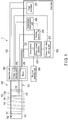
- FIG. 1 is a schematic view of a configuration of an endoscope system as an example of an insertion apparatus according to an embodiment of the present invention.
- an endoscope system 1 includes an endoscope 100, a controller 200, and a rotation operation unit 360.
- the endoscope 100 is a rotary self-propelled type endoscope, and includes an insertion section 110.
- the insertion section 110 is an elongated shape, and is configured to be inserted into a body.
- the endoscope 100 also includes an operation unit 160 attached to the insertion section 110, by which various operations for the endoscope 100 are performed.
- the operation unit 160 is held by a user.
- the operation unit 160 of the endoscope 100 and the controller 200 are connected by a universal cable 190.
- the side of a distal end of the insertion section 110 is referred to as a distal end side.
- the side of the insertion section 110 at which the operation unit 160 is provided is referred to as a proximal end side.
- the direction from the distal end to the proximal end of the insertion section 110 is referred to as a longitudinal direction.
- the insertion section 110 includes a distal end hard section 112, a bending section 114, and a coiled hose section 116.
- the distal end hard section 112 is an edge of the distal end of the insertion section 110, and is formed to not be bent.
- the distal end hard section 112 includes an imaging element 120.
- the imaging element 120 generates an image signal based on a subject image at the distal end side of the insertion section 110, for example.
- the image signal generated by the imaging element 120 is transmitted to an image processor 201 of the controller via an image signal line passing through the insertion section 110 and the universal cable 190.
- the bending section 114 is formed at the proximal end side of the distal end hard section 112, and is formed to be actively bent in accordance with an operation of an operation member (not shown in the drawings) provided to the operation unit 160.
- the coiled hose section 116 is formed at the proximal end side of the bending section 114, and is formed to be passively bent by external force.
- the coiled hose section 116 is provided with a rotation section 130.
- the rotation section 130 is provided with a spiral tube 132 which is a rotational housing at the distal end.
- FIG. 2 is a cross-sectional view of the enlarged rotation section 130.
- the rotation section 130 includes a housing 130a, a drive gear 130b, a drive shaft 130c, and a rotation transmission rubber 130d.
- the housing 130a is a cylindrical housing, and rotates in accordance with the rotation of a motor 150 built in the operation unit 160.
- the drive gear 130b is engaged with the housing 130a.
- the drive gear 130b transmits a driving power of the motor 150 transmitted from the drive shaft 130c to the housing 130a.
- the drive shaft 130c is connected to the motor 150, so as to rotate in accordance with the rotation of the motor 150, and to transmit the driving power of the motor 150 to the drive gear 130b.
- the rotation transmission rubber 130d has a cylindrical shape that covers an exterior of the housing 130a, and is a driving power transmission member that rotates in accordance with the rotation of the housing 130a and transmits the driving power of the motor 150 to the spiral tube 132.
- the spiral tube 132 is formed of a soft material such as a rubber or a resin, for example, in a tubular shape.
- the spiral tube 132 is provided with a spiral fin 134 along the longitudinal axis of the spiral tube 132 on the outer peripheral surface.
- the spiral tube 132 may be configured to be removable from the rotation section 130.
- a temperature sensor 118 that functions as a temperature detector is provided in the vicinity of the rotation section 130.
- the temperature sensor 118 is a sensor that detects the temperature inside of the rotation section 130, and preferably detects the temperature of the rotation transmission rubber 130d of the rotation section 130.
- An output signal of the temperature sensor 118 is transmitted to a temperature measurement unit 204 of the controller 200 through a sensor signal line passing through the insertion section 110 and the universal cable 190.
- a contact type temperature sensor such as a thermocouple or a thermistor, or a non-contact type temperature sensor such as a radiation thermometer may be adopted as the temperature sensor 118.
- the contact type temperature sensor is disposed to be in contact with the rotation transmission rubber 130d, as shown in FIG. 2 .
- the non-contact type temperature sensor is disposed in the vicinity of the rotation transmission rubber 130d.
- the temperature sensor 118 according to the present embodiment is not limited to a sensor having a particular structure, as long as it can detect the temperature of the vicinity of the rotation transmission rubber 130d.
- the temperature sensor 118 is arranged to measure the temperature at a point of the rotation transmission rubber 130d.
- the temperature sensor 118 may be arranged to measure the temperature at multiple points of the rotation transmission rubber 130d. In this case, the average of the temperature measured at the multiple points, for example, is assumed to be the temperature of the rotation transmission rubber 130d.
- a heater 119 which is used as a heating element is provided in the vicinity of the rotation section 130 of the insertion section 110.
- the heater 119 is a heating element that heats inside of the rotation section 130, preferably the rotation transmission rubber 130d of the rotation section 130. As shown in FIG. 2 , for example, the heater 119 is provided inside of the rotation section 130.
- the heater 119 is connected to a heating control unit 205 of the controller 200 via a heater signal line passing through the insertion section 110 and the universal cable 190.
- the heater 119 heats the rotation section 130 in accordance with control by the heating control unit 205.
- a member that generates heat by allowing current to flow through a metallic resistant film such as nichrome, etc. is adopted as the heater 119.
- the heater 119 is not limited as long as the rotation section 130 can be heated from room temperature to body temperature, which is a temperature at which the rotation section 130 is used.
- the heater 119 shown in FIG. 2 is a heating element that heats the rotation section 130 without contact, but may be an element that heats the rotation section 130 by being brought into contact with the rotation section 130.
- the motor 150 is connected to a drive control unit 202 of the controller 200 via an actuator current signal line passing through the operation unit 160 and the universal cable 190.
- the motor 150 operates by an operation using the rotation operation unit 360.
- the rotation power of the motor 150 is transmitted to the rotation section 130.
- the fin 134 provided in the spiral tube 132 rotates around the longitudinal axis. If the fin 134 rotates while being in contact with a wall part such as an inner paries of a lumen, friction is generated to allow the insertion section 110 to self-propel. For example, in a small intestine or a large intestine, if the fin 134 is in contact with folds in the inner paries of the small intestine or the large intestine, friction is applied to the insertion section 110. The insertion section 110 self-propels by the friction.
- the self-propelling of the insertion section 110 assists the insertion operation or the removal operation of the insertion section 110 by the user.
- the motor 150 includes a pulse generator.
- the pulse generator generates a pulse signal (rotational speed signal) in accordance with the rotational speed of the motor 150, and inputs the rotational speed signal to the controller 200 via a rotational speed signal line passing through the universal cable 190.
- the rotational speed of the motor 150 is controlled by the rotational speed signal.
- the operation unit 160 is provided with a unique data storage unit 170.
- the unique data storage unit 170 stores data unique to the endoscope 100, such as a torque limit value, etc.
- the unique data storage unit 170 is formed, for example, of a nonvolatile memory.
- the torque limit value is a threshold of a driving current to activate a torque limit function.
- the torque limit value stored in the unique data storage unit 170 is a torque limit value at a predetermined set temperature (for example, body temperature (approximately 40 °C)), and the unique data storage unit 170 also stores the set temperature.
- the set temperature is preferably set depending on various conditions such as temperature properties of the rotation transmission rubber 130d or temperature properties of the motor 150.
- the rotation operation unit 360 may be a footswitch, for example.
- the footswitch generates a command signal in accordance with a pressure amount applied to a pedal when a user stepped on the pedal.
- the controller 200 controls each element of the endoscope system 1.
- the controller 200 includes the image processor 201, the drive control unit 202, a torque limit value storage unit 203, the temperature measurement unit 204 and the heating control unit 205.
- the image processor 201 performs image processing to an image signal that is generated at the imaging element 120 and input to the image processor 201 through the insertion section 110 and the universal cable 190.
- the image processor 201 inputs the processed image signal to the display unit not shown in the drawings to display an endoscope image on the display unit.
- the drive control unit 202 is configured, for example, by an ASIC, and acquires a command signal generated at the rotation operation unit 360 to convert it to a command value. In addition, the drive control unit 202 obtains a rotational speed signal of the motor 150. The drive control unit 202 then generates a driving power based on the command value and the rotational speed signal. The drive control unit 202 further supplies the driving power to the motor 150 to drive the motor 150.
- the drive control unit 202 includes a drive current detector 2021. The drive control unit 202 compares the driving current value with a torque limit value stored in the torque limit value storage unit 203, and stops the rotation of the motor 150 when the driving current reaches or exceeds the torque limit value. By the torque limit function, the generation of excessive torque by the motor 150 is suppressed. Accordingly, it is possible to reduce a possibility of applying unnecessary force to the inner paries of a lumen.
- the torque limit value storage unit 203 reads a torque limit value from the unique data storage unit 170, and stores the read torque limit value.
- the torque limit value storage unit 203 is formed, for example, of a volatile memory.
- the temperature measurement unit 204 measures the temperature of the rotation section 130 based on an output of the temperature sensor 118. For example, the temperature measurement unit 204 acquires a signal generated proportionally to the temperature detected by the temperature sensor 118, and converts the acquired signal into a temperature.
- the heating control unit 205 includes a power supply for the heater 119.
- the heating control unit 205 compares the temperature measured at the temperature measurement unit 204 with the set temperature stored in the unique data storage unit 170, and allows the heater 119 to heat the rotation section 130 if the measured temperature is lower than the set temperature.
- the hardness of rubber changes depending on a change in temperature. If the hardness of the rotation section 130 changes, the operation of the spiral tube 132 is affected by the change. Accordingly, there is a possibility that the torque limit function, etc. is not normally activated. For example, there is a case where the torque limit function is not activated when the torque limit function should be activated, or the torque limit function is erroneously activated when the torque limit function is unnecessary.
- the temperature of the rotation transmission rubber 130d of the rotation section 130 is maintained to be the set temperature so that the rotation section 130 or the spiral tube 132 is operable under the same environment.
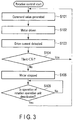
- FIG. 3 is a flowchart of rotation control of the motor 150 of the endoscope 100.
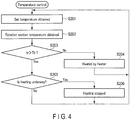
- FIG. 4 is a flowchart of temperature control of the rotation section 130.
- the controls of FIGS. 3 and 4 are performed asynchronously, for example. Of course, the controls of FIGS. 3 and 4 may be performed synchronously.
- the operation shown in FIG. 3 is performed by the drive control unit 202.
- the operation shown in FIG. 3 is initiated when the rotation operation unit 360 of the endoscope system 1 is operated.
- the drive control unit 202 receives a command signal from the rotation operation unit 360, and generates, based on the command signal, a command value for the rotational speed in accordance with the pressing amount of the pedal of the rotation operation unit 360 by the user.
- step S102 the drive control unit 202 drives the motor 150 in accordance with the deviation between the command value and the current value of the rotational speed based on the rotational speed signal obtained from the pulse generator of the motor 150.
- step S103 the drive control unit 202 obtains a current driving current value Ti.
- step S104 the drive control unit 202 compares the driving current value Ti and the torque limit value Tlimit stored in the torque limit value storage unit 203, and determines whether or not Tlimit is lower than Ti (Tlimit ⁇ Ti). In step S104, if it is determined that Tlimit ⁇ Ti is not satisfied, the processing returns to step S101. In step S104, if it is determined that Tlimit ⁇ Ti is satisfied, the processing proceeds to step S105.
- step S105 the drive control unit 202 enables the torque limit function to stop the power supplied to the motor 150 and to stop driving of the motor 150.
- step S106 the drive control unit 202 determines whether or not the operation of the rotation operation unit 360 is deactivated. In step S106, if it is determined that the operation of the rotation operation unit 360 is not deactivated, the processing stands by. In this case, the motor 150 remains stopped. In step S106, if it is determined that the operation of the rotation operation unit 360 is deactivated, the processing returns to step S101. In this case, the torque limit function is deactivated.
- the operation shown in FIG. 4 is performed by the heating control unit 205.
- the operation shown in FIG. 4 is initiated when the endoscope system 1 is powered on.
- the heating control unit 205 obtains a set temperature Tt stored in the unique data storage unit 170 of the endoscope 100 through the temperature measurement unit 204.
- step S202 the heating control unit 205 obtains a temperature tr of the rotation section 130 that is measured by the temperature measurement unit 204 based on an output of the temperature sensor 118.
- step S203 the heating control unit 205 compares the set temperature Tt with the rotation section temperature tr, and determines whether or not tr is higher than Tt (tr > Tt). In step S203, if it is determined that tr > Tt is not satisfied, the processing proceeds to step S204. In step S203, if it is determined that tr > Tt is satisfied, the processing proceeds to step S205.
- step S204 the heating control unit 205 controls the heater 119 to heat the rotation section 130. Subsequently, the processing returns to step S201.
- step S205 the heating control unit 205 determines whether or not the rotation section 130 is currently heated by the heater 119. In step S205, if it is determined that the rotation section 130 is not currently heated, the processing returns to step S201. In step S205, if it is determined that the rotation section 130 is currently heated, the processing proceeds to step S206.
- step S206 the heating control unit 205 controls the heater 119 to stop heating of the rotation section 130. Subsequently, the processing returns to step S201.
- the rotation section 130 when the temperature of the rotation section 130 is below the set temperature, the rotation section 130 is heated to stably perform the torque limit function.
- the rotation section 130 is only heated. It may be necessary not only to heat the rotation section 130 when the temperature becomes lower than the set temperature, but also to cool the rotation section 130 when the temperature becomes higher than the set temperature, in order to stably perform the torque limit function, as stated above.
- the endoscope 100 which is at room temperature of approximately 20 °C, is inserted into a body (at approximately 36 °C) . Accordingly, it is assumed that cooling is not necessary.
- the endoscope system 1 may be provided with a cooling mechanism that cools the rotation section 130 when the temperature becomes higher than the set temperature.
- FIG. 5 is a diagram showing a configuration of an endoscope system of modification 1.
- the same structures as explained with reference to FIG. 1 are indicated with the same reference numerals, and the explanations thereof will be omitted.
- a unique data storage unit 170 of modification 1 stores a torque limit setting table.
- the torque limit setting table is a table in which the temperature of a rotation section 130 and the torque limit value are associated.
- FIG. 6 is an example of a torque limit setting table.
- the torque limit setting table is a table in which the torque limit values tlimit are associated with the temperatures in preset measurement points every 0.5 °C or 1 °C.
- the torque limit value tlimit of the torque limit setting table is obtained by actual measurement, for example, and the values shown in FIG. 6 are merely an example.
- the torque limit value tlimit at a particular temperature between the measurement points shown in FIG. 6 is calculated by an interpolation operation using torque limit values tlimit at two closest measurement points that are lower or higher than the temperature.
- a controller 200 of modification 1 is provided with a torque limit value correction unit 206.
- the torque limit value correction unit 206 obtains a torque limit value tlimit corresponding to the temperature measured at a temperature measurement unit 204 from the torque limit setting table, and overwrites the setting of a torque limit value storage unit 203.
- FIG. 7 is a flowchart of correction control for torque limit values.
- the operation shown in FIG. 7 is performed by the torque limit value correction unit 206.
- the operation of FIG. 7 is performed asynchronously to the operations of FIGS. 3 and 4 , for example.
- the operation shown in FIG. 7 is initiated when the endoscope system 1 is powered on.
- the torque limit value correction unit 206 obtains a temperature tr of the rotation section 130 that is measured by the temperature measurement unit 204 based on an output of the temperature sensor 118.
- step S302 the torque limit value correction unit 206 obtains a torque limit value tlimit in accordance with the temperature measurement result, from the torque limit setting table stored in the unique data storage unit 170 of the endoscope 100.
- step S303 the torque limit value correction unit 206 determines whether or not the torque limit value Tlimit stored in the torque limit value storage unit 203 is different from the torque limit value tlimit obtained in step S302. In step S303, if it is determined that the torque limit value Tlimit is not different from the torque limit value tlimit, the processing returns to step S301. In this case, the rotation control of FIG. 3 is performed with the torque limit value that has been stored in the torque limit value storage unit 203. In step S303, if it is determined that the torque limit value Tlimit is different from the torque limit value tlimit, the processing proceeds to step S304. In step S304, the torque limit value correction unit 206 performs correction to replace the torque limit value Tlimit with the torque limit value tlimit. Subsequently, the processing returns to step S301. In this case, the rotation control of FIG. 3 is performed with the replaced torque limit value.
- FIG. 8 is a diagram showing a configuration of an endoscope system of modification 2.
- the same structures as explained with reference to FIG. 1 are indicated with the same reference numerals, and the explanations thereof will be omitted.
- a heater 119 is, for example, a metallic plate.
- the heater 119 is connected to a metal line 119a covered with a heat insulator.
- the metal line 119a is connected to a motor 150 through a switch 180.
- the switch 180 is connected to a heating control unit 205 through a signal line, and switches the state between the heater 119 and the motor 150 between a heat transfer state and a heat insulation state, in accordance with a control signal from the heating control unit 205.
- the heating control unit 205 turns the switch 180 on when the temperature of a rotation section 130 is lower than the set temperature to change the state between the heater 119 and the motor 150 to be the heat transfer state. In this case, heat generated by driving the motor 150 is transmitted to the heater 119 through the metal line 119a. Then, the heater 119, which is a metallic plate for example, is heated, and accordingly, the rotation section 130 is heated.
- the heating control unit 205 may not have a power supply for the heater 119.
- FIG. 9 is an enlarged diagram showing a rotation section 130 and a vicinity of the rotation section 130 of modification 3.
- a heater 119 is provided to heat the entire spiral tube 132 including the rotation section 130. With this configuration, it is possible to control the entire temperature of the spiral tube 132 including the rotation section 130 to be a set temperature.
- the operations described in the above embodiment may be stored in the form of programs executable by a CPU (which is a computer) or the like.
- the programs can be stored in storage mediums of external storage devices, such as a memory card, a magnetic disk, an optical disk or a semiconductor memory, and distributed.
- the CPU or the like reads the programs from a storage medium of an external storage device, and the operations can be executed and controlled based on the read programs.
Landscapes
- Health & Medical Sciences (AREA)
- Life Sciences & Earth Sciences (AREA)
- Surgery (AREA)
- Engineering & Computer Science (AREA)
- Biomedical Technology (AREA)
- Molecular Biology (AREA)
- Pathology (AREA)
- Radiology & Medical Imaging (AREA)
- Nuclear Medicine, Radiotherapy & Molecular Imaging (AREA)
- Biophysics (AREA)
- Physics & Mathematics (AREA)
- Heart & Thoracic Surgery (AREA)
- Medical Informatics (AREA)
- Optics & Photonics (AREA)
- Animal Behavior & Ethology (AREA)
- General Health & Medical Sciences (AREA)
- Public Health (AREA)
- Veterinary Medicine (AREA)
- Signal Processing (AREA)
- Instruments For Viewing The Inside Of Hollow Bodies (AREA)
- Endoscopes (AREA)
Abstract
Description
- The present invention relates to a rotary self-propelled type insertion apparatus.
- Generally, an insertion apparatus such as an endoscope apparatus is inserted into a lumen. Among these types of insertion apparatuses, an insertion apparatus which is called a rotary self-propelled type has been known. The rotary self-propelled type endoscope apparatus is provided, for example, with a rotational housing which is called a spiral tube, etc. in which a spiral-shaped fin is formed on an outer peripheral surface of the insertion section. When the rotating housing is rotated, the fin formed to the rotational housing is brought into contact with an inner wall of a lumen, and generates friction. The insertion section self-propels in an insertion direction or in a removal direction by the friction. For example, Jpn. Pat. Appln. KOKAI Publication No.
2014-064686 - General insertion apparatuses have a torque limit function to stop the rotation of a motor that rotates a rotational housing when a driving current of the motor reaches or exceeds a threshold. A transmission member formed of rubber is disposed between a rotation section that rotates the rotational housing and the rotational housing. Rubber has a property of its hardness changing due to a change in ambient temperature. If the hardness of the rotation section changes, the operation of a spiral tube will be affected.
- The present invention has been made in consideration of the above circumstances, and an objective thereof is to provide an insertion apparatus which is capable of stably operating the spiral tube regardless of the ambient temperature.
- To achieve the object, an insertion apparatus according to an aspect of the invention comprises: an insertion section having an elongated shape; a rotational housing provided on an outer peripheral surface of the insertion section to be rotatable about a longitudinal axis; a motor that rotates the rotational housing; a drive control unit that supplies a driving current to the motor to control driving of the motor; a temperature detector provided in the rotational housing, that detects a temperature of the rotational housing; a temperature measurement unit that measures a temperature in a vicinity of the rotational housing based on a detection result obtained from the temperature detector; a heating element provided in the rotational housing and used for heating; and a heating control unit that controls the heating element to perform heating when a measurement result of the temperature measurement unit is lower than a predetermined temperature.
-
-
FIG. 1 is a schematic view of a configuration of an endoscope system as an example of an insertion apparatus according to an embodiment of the present invention; -
FIG. 2 is a cross-sectional view of an enlarged rotation section; -
FIG. 3 is a flowchart of rotation control; -
FIG. 4 is a flowchart of temperature control; -
FIG. 5 is a diagram showing a configuration of an endoscope system ofmodification 1; -
FIG. 6 is an example of a torque limit setting table; -
FIG. 7 is a flowchart of correction control for torque limit values; -
FIG. 8 is a diagram showing a configuration of an endoscope system of modification 2; and -
FIG. 9 is an enlarged diagram showing a rotation section and a vicinity of the rotation section of modification 3. - Hereinafter, an embodiment of the present invention will be described with reference to the drawings.
FIG. 1 is a schematic view of a configuration of an endoscope system as an example of an insertion apparatus according to an embodiment of the present invention. As shown inFIG. 1 , anendoscope system 1 includes anendoscope 100, acontroller 200, and arotation operation unit 360. - The
endoscope 100 is a rotary self-propelled type endoscope, and includes aninsertion section 110. Theinsertion section 110 is an elongated shape, and is configured to be inserted into a body. Theendoscope 100 also includes anoperation unit 160 attached to theinsertion section 110, by which various operations for theendoscope 100 are performed. Theoperation unit 160 is held by a user. Theoperation unit 160 of theendoscope 100 and thecontroller 200 are connected by auniversal cable 190. In the following explanation, the side of a distal end of theinsertion section 110 is referred to as a distal end side. The side of theinsertion section 110 at which theoperation unit 160 is provided is referred to as a proximal end side. The direction from the distal end to the proximal end of theinsertion section 110 is referred to as a longitudinal direction. - The
insertion section 110 includes a distal endhard section 112, abending section 114, and a coiledhose section 116. The distal endhard section 112 is an edge of the distal end of theinsertion section 110, and is formed to not be bent. - The distal end
hard section 112 includes animaging element 120. Theimaging element 120 generates an image signal based on a subject image at the distal end side of theinsertion section 110, for example. The image signal generated by theimaging element 120 is transmitted to animage processor 201 of the controller via an image signal line passing through theinsertion section 110 and theuniversal cable 190. Thebending section 114 is formed at the proximal end side of the distal endhard section 112, and is formed to be actively bent in accordance with an operation of an operation member (not shown in the drawings) provided to theoperation unit 160. The coiledhose section 116 is formed at the proximal end side of thebending section 114, and is formed to be passively bent by external force. - The coiled
hose section 116 is provided with arotation section 130. Therotation section 130 is provided with aspiral tube 132 which is a rotational housing at the distal end.FIG. 2 is a cross-sectional view of the enlargedrotation section 130. As shown inFIG. 2 , therotation section 130 includes ahousing 130a, adrive gear 130b, adrive shaft 130c, and arotation transmission rubber 130d. Thehousing 130a is a cylindrical housing, and rotates in accordance with the rotation of amotor 150 built in theoperation unit 160. Thedrive gear 130b is engaged with thehousing 130a. Thedrive gear 130b transmits a driving power of themotor 150 transmitted from thedrive shaft 130c to thehousing 130a. Thedrive shaft 130c is connected to themotor 150, so as to rotate in accordance with the rotation of themotor 150, and to transmit the driving power of themotor 150 to thedrive gear 130b. Therotation transmission rubber 130d has a cylindrical shape that covers an exterior of thehousing 130a, and is a driving power transmission member that rotates in accordance with the rotation of thehousing 130a and transmits the driving power of themotor 150 to thespiral tube 132. - The
spiral tube 132 is formed of a soft material such as a rubber or a resin, for example, in a tubular shape. Thespiral tube 132 is provided with aspiral fin 134 along the longitudinal axis of thespiral tube 132 on the outer peripheral surface. Thespiral tube 132 may be configured to be removable from therotation section 130. - A
temperature sensor 118 that functions as a temperature detector is provided in the vicinity of therotation section 130. Thetemperature sensor 118 is a sensor that detects the temperature inside of therotation section 130, and preferably detects the temperature of therotation transmission rubber 130d of therotation section 130. An output signal of thetemperature sensor 118 is transmitted to atemperature measurement unit 204 of thecontroller 200 through a sensor signal line passing through theinsertion section 110 and theuniversal cable 190. For example, a contact type temperature sensor such as a thermocouple or a thermistor, or a non-contact type temperature sensor such as a radiation thermometer may be adopted as thetemperature sensor 118. The contact type temperature sensor is disposed to be in contact with therotation transmission rubber 130d, as shown inFIG. 2 . The non-contact type temperature sensor is disposed in the vicinity of therotation transmission rubber 130d. Thetemperature sensor 118 according to the present embodiment is not limited to a sensor having a particular structure, as long as it can detect the temperature of the vicinity of therotation transmission rubber 130d. In an example shown inFIG. 2 , thetemperature sensor 118 is arranged to measure the temperature at a point of therotation transmission rubber 130d. However, thetemperature sensor 118 may be arranged to measure the temperature at multiple points of therotation transmission rubber 130d. In this case, the average of the temperature measured at the multiple points, for example, is assumed to be the temperature of therotation transmission rubber 130d. - A
heater 119 which is used as a heating element is provided in the vicinity of therotation section 130 of theinsertion section 110. Theheater 119 is a heating element that heats inside of therotation section 130, preferably therotation transmission rubber 130d of therotation section 130. As shown inFIG. 2 , for example, theheater 119 is provided inside of therotation section 130. Theheater 119 is connected to aheating control unit 205 of thecontroller 200 via a heater signal line passing through theinsertion section 110 and theuniversal cable 190. Theheater 119 heats therotation section 130 in accordance with control by theheating control unit 205. A member that generates heat by allowing current to flow through a metallic resistant film such as nichrome, etc. is adopted as theheater 119. Theheater 119 is not limited as long as therotation section 130 can be heated from room temperature to body temperature, which is a temperature at which therotation section 130 is used. For example, theheater 119 shown inFIG. 2 is a heating element that heats therotation section 130 without contact, but may be an element that heats therotation section 130 by being brought into contact with therotation section 130. - The
motor 150 is connected to adrive control unit 202 of thecontroller 200 via an actuator current signal line passing through theoperation unit 160 and theuniversal cable 190. - The
motor 150 operates by an operation using therotation operation unit 360. The rotation power of themotor 150 is transmitted to therotation section 130. As a result, thefin 134 provided in thespiral tube 132 rotates around the longitudinal axis. If thefin 134 rotates while being in contact with a wall part such as an inner paries of a lumen, friction is generated to allow theinsertion section 110 to self-propel. For example, in a small intestine or a large intestine, if thefin 134 is in contact with folds in the inner paries of the small intestine or the large intestine, friction is applied to theinsertion section 110. Theinsertion section 110 self-propels by the friction. The self-propelling of theinsertion section 110 assists the insertion operation or the removal operation of theinsertion section 110 by the user. Themotor 150 includes a pulse generator. The pulse generator generates a pulse signal (rotational speed signal) in accordance with the rotational speed of themotor 150, and inputs the rotational speed signal to thecontroller 200 via a rotational speed signal line passing through theuniversal cable 190. The rotational speed of themotor 150 is controlled by the rotational speed signal. - The
operation unit 160 is provided with a uniquedata storage unit 170. The uniquedata storage unit 170 stores data unique to theendoscope 100, such as a torque limit value, etc. The uniquedata storage unit 170 is formed, for example, of a nonvolatile memory. The torque limit value is a threshold of a driving current to activate a torque limit function. The torque limit value stored in the uniquedata storage unit 170 is a torque limit value at a predetermined set temperature (for example, body temperature (approximately 40 °C)), and the uniquedata storage unit 170 also stores the set temperature. The set temperature is preferably set depending on various conditions such as temperature properties of therotation transmission rubber 130d or temperature properties of themotor 150. - The
rotation operation unit 360 may be a footswitch, for example. The footswitch generates a command signal in accordance with a pressure amount applied to a pedal when a user stepped on the pedal. - The
controller 200 controls each element of theendoscope system 1. Thecontroller 200 includes theimage processor 201, thedrive control unit 202, a torque limitvalue storage unit 203, thetemperature measurement unit 204 and theheating control unit 205. - The
image processor 201 performs image processing to an image signal that is generated at theimaging element 120 and input to theimage processor 201 through theinsertion section 110 and theuniversal cable 190. Theimage processor 201 inputs the processed image signal to the display unit not shown in the drawings to display an endoscope image on the display unit. - The
drive control unit 202 is configured, for example, by an ASIC, and acquires a command signal generated at therotation operation unit 360 to convert it to a command value. In addition, thedrive control unit 202 obtains a rotational speed signal of themotor 150. Thedrive control unit 202 then generates a driving power based on the command value and the rotational speed signal. Thedrive control unit 202 further supplies the driving power to themotor 150 to drive themotor 150. Thedrive control unit 202 includes adrive current detector 2021. Thedrive control unit 202 compares the driving current value with a torque limit value stored in the torque limitvalue storage unit 203, and stops the rotation of themotor 150 when the driving current reaches or exceeds the torque limit value. By the torque limit function, the generation of excessive torque by themotor 150 is suppressed. Accordingly, it is possible to reduce a possibility of applying unnecessary force to the inner paries of a lumen. - The torque limit
value storage unit 203 reads a torque limit value from the uniquedata storage unit 170, and stores the read torque limit value. The torque limitvalue storage unit 203 is formed, for example, of a volatile memory. - The
temperature measurement unit 204 measures the temperature of therotation section 130 based on an output of thetemperature sensor 118. For example, thetemperature measurement unit 204 acquires a signal generated proportionally to the temperature detected by thetemperature sensor 118, and converts the acquired signal into a temperature. - The
heating control unit 205 includes a power supply for theheater 119. Theheating control unit 205 compares the temperature measured at thetemperature measurement unit 204 with the set temperature stored in the uniquedata storage unit 170, and allows theheater 119 to heat therotation section 130 if the measured temperature is lower than the set temperature. Generally, the hardness of rubber changes depending on a change in temperature. If the hardness of therotation section 130 changes, the operation of thespiral tube 132 is affected by the change. Accordingly, there is a possibility that the torque limit function, etc. is not normally activated. For example, there is a case where the torque limit function is not activated when the torque limit function should be activated, or the torque limit function is erroneously activated when the torque limit function is unnecessary. Thus, in the present embodiment, the temperature of therotation transmission rubber 130d of therotation section 130 is maintained to be the set temperature so that therotation section 130 or thespiral tube 132 is operable under the same environment. - Next, the operation of the
endoscope system 1 according to the present embodiment will be explained.FIG. 3 is a flowchart of rotation control of themotor 150 of theendoscope 100.FIG. 4 is a flowchart of temperature control of therotation section 130. The controls ofFIGS. 3 and4 are performed asynchronously, for example. Of course, the controls ofFIGS. 3 and4 may be performed synchronously. - First, the rotation control will be explained with reference to
FIG. 3 . The operation shown inFIG. 3 is performed by thedrive control unit 202. For example, the operation shown inFIG. 3 is initiated when therotation operation unit 360 of theendoscope system 1 is operated. In step S101, thedrive control unit 202 receives a command signal from therotation operation unit 360, and generates, based on the command signal, a command value for the rotational speed in accordance with the pressing amount of the pedal of therotation operation unit 360 by the user. - In step S102, the
drive control unit 202 drives themotor 150 in accordance with the deviation between the command value and the current value of the rotational speed based on the rotational speed signal obtained from the pulse generator of themotor 150. - In step S103, the
drive control unit 202 obtains a current driving current value Ti. In step S104, thedrive control unit 202 compares the driving current value Ti and the torque limit value Tlimit stored in the torque limitvalue storage unit 203, and determines whether or not Tlimit is lower than Ti (Tlimit < Ti). In step S104, if it is determined that Tlimit < Ti is not satisfied, the processing returns to step S101. In step S104, if it is determined that Tlimit < Ti is satisfied, the processing proceeds to step S105. - In step S105, the
drive control unit 202 enables the torque limit function to stop the power supplied to themotor 150 and to stop driving of themotor 150. - In step S106, the
drive control unit 202 determines whether or not the operation of therotation operation unit 360 is deactivated. In step S106, if it is determined that the operation of therotation operation unit 360 is not deactivated, the processing stands by. In this case, themotor 150 remains stopped. In step S106, if it is determined that the operation of therotation operation unit 360 is deactivated, the processing returns to step S101. In this case, the torque limit function is deactivated. - Next, the temperature control will be explained with reference to
FIG. 4 . The operation shown inFIG. 4 is performed by theheating control unit 205. For example, the operation shown inFIG. 4 is initiated when theendoscope system 1 is powered on. In step S201, theheating control unit 205 obtains a set temperature Tt stored in the uniquedata storage unit 170 of theendoscope 100 through thetemperature measurement unit 204. - In step S202, the
heating control unit 205 obtains a temperature tr of therotation section 130 that is measured by thetemperature measurement unit 204 based on an output of thetemperature sensor 118. - In step S203, the
heating control unit 205 compares the set temperature Tt with the rotation section temperature tr, and determines whether or not tr is higher than Tt (tr > Tt). In step S203, if it is determined that tr > Tt is not satisfied, the processing proceeds to step S204. In step S203, if it is determined that tr > Tt is satisfied, the processing proceeds to step S205. - In step S204, the
heating control unit 205 controls theheater 119 to heat therotation section 130. Subsequently, the processing returns to step S201. - In step S205, the
heating control unit 205 determines whether or not therotation section 130 is currently heated by theheater 119. In step S205, if it is determined that therotation section 130 is not currently heated, the processing returns to step S201. In step S205, if it is determined that therotation section 130 is currently heated, the processing proceeds to step S206. - In step S206, the
heating control unit 205 controls theheater 119 to stop heating of therotation section 130. Subsequently, the processing returns to step S201. - As explained above, according to the present embodiment, when the temperature of the
rotation section 130 is below the set temperature, therotation section 130 is heated to stably perform the torque limit function. - In the present embodiment, an example where the
rotation section 130 is only heated is presented. It may be necessary not only to heat therotation section 130 when the temperature becomes lower than the set temperature, but also to cool therotation section 130 when the temperature becomes higher than the set temperature, in order to stably perform the torque limit function, as stated above. However, in the environment where theendoscope 100 is used, theendoscope 100, which is at room temperature of approximately 20 °C, is inserted into a body (at approximately 36 °C) . Accordingly, it is assumed that cooling is not necessary. Of course, theendoscope system 1 may be provided with a cooling mechanism that cools therotation section 130 when the temperature becomes higher than the set temperature. - A modification of the present embodiment will be explained below.
FIG. 5 is a diagram showing a configuration of an endoscope system ofmodification 1. The same structures as explained with reference toFIG. 1 are indicated with the same reference numerals, and the explanations thereof will be omitted. - A unique
data storage unit 170 ofmodification 1 stores a torque limit setting table. The torque limit setting table is a table in which the temperature of arotation section 130 and the torque limit value are associated.FIG. 6 is an example of a torque limit setting table. As shown inFIG. 6 , the torque limit setting table is a table in which the torque limit values tlimit are associated with the temperatures in preset measurement points every 0.5 °C or 1 °C. The torque limit value tlimit of the torque limit setting table is obtained by actual measurement, for example, and the values shown inFIG. 6 are merely an example. The torque limit value tlimit at a particular temperature between the measurement points shown inFIG. 6 is calculated by an interpolation operation using torque limit values tlimit at two closest measurement points that are lower or higher than the temperature. - In addition, a
controller 200 ofmodification 1 is provided with a torque limitvalue correction unit 206. The torque limitvalue correction unit 206 obtains a torque limit value tlimit corresponding to the temperature measured at atemperature measurement unit 204 from the torque limit setting table, and overwrites the setting of a torque limitvalue storage unit 203. -
FIG. 7 is a flowchart of correction control for torque limit values. The operation shown inFIG. 7 is performed by the torque limitvalue correction unit 206. The operation ofFIG. 7 is performed asynchronously to the operations ofFIGS. 3 and4 , for example. For example, the operation shown inFIG. 7 is initiated when theendoscope system 1 is powered on. In step S301, the torque limitvalue correction unit 206 obtains a temperature tr of therotation section 130 that is measured by thetemperature measurement unit 204 based on an output of thetemperature sensor 118. - In step S302, the torque limit
value correction unit 206 obtains a torque limit value tlimit in accordance with the temperature measurement result, from the torque limit setting table stored in the uniquedata storage unit 170 of theendoscope 100. - In step S303, the torque limit
value correction unit 206 determines whether or not the torque limit value Tlimit stored in the torque limitvalue storage unit 203 is different from the torque limit value tlimit obtained in step S302. In step S303, if it is determined that the torque limit value Tlimit is not different from the torque limit value tlimit, the processing returns to step S301. In this case, the rotation control ofFIG. 3 is performed with the torque limit value that has been stored in the torque limitvalue storage unit 203. In step S303, if it is determined that the torque limit value Tlimit is different from the torque limit value tlimit, the processing proceeds to step S304. In step S304, the torque limitvalue correction unit 206 performs correction to replace the torque limit value Tlimit with the torque limit value tlimit. Subsequently, the processing returns to step S301. In this case, the rotation control ofFIG. 3 is performed with the replaced torque limit value. - As explained above, according to
modification 1, it is possible to more stably enable the torque limit function, by correcting the torque limit value in accordance with the temperature, in addition to the temperature control of therotation section 130. - Next, modification 2 will be explained.
FIG. 8 is a diagram showing a configuration of an endoscope system of modification 2. The same structures as explained with reference toFIG. 1 are indicated with the same reference numerals, and the explanations thereof will be omitted. - In modification 2, a
heater 119 is, for example, a metallic plate. Theheater 119 is connected to ametal line 119a covered with a heat insulator. Themetal line 119a is connected to amotor 150 through aswitch 180. Theswitch 180 is connected to aheating control unit 205 through a signal line, and switches the state between theheater 119 and themotor 150 between a heat transfer state and a heat insulation state, in accordance with a control signal from theheating control unit 205. - In this configuration, the
heating control unit 205 turns theswitch 180 on when the temperature of arotation section 130 is lower than the set temperature to change the state between theheater 119 and themotor 150 to be the heat transfer state. In this case, heat generated by driving themotor 150 is transmitted to theheater 119 through themetal line 119a. Then, theheater 119, which is a metallic plate for example, is heated, and accordingly, therotation section 130 is heated. - According to modification 2, the
heating control unit 205 may not have a power supply for theheater 119. - Next, modification 3 will be explained.
FIG. 9 is an enlarged diagram showing arotation section 130 and a vicinity of therotation section 130 of modification 3. In modification 3, aheater 119 is provided to heat theentire spiral tube 132 including therotation section 130. With this configuration, it is possible to control the entire temperature of thespiral tube 132 including therotation section 130 to be a set temperature. - The present invention has been explained based on the embodiment; however, the present invention is not limited to the embodiment. The present invention may, of course, be modified in various ways without departing from the spirit and scope of the invention. In addition, the terms "first" or "next" are used for the explanation of the flowchart showing each operation; however, the sequence of the operation is not limited by these terms.
- The operations described in the above embodiment may be stored in the form of programs executable by a CPU (which is a computer) or the like. The programs can be stored in storage mediums of external storage devices, such as a memory card, a magnetic disk, an optical disk or a semiconductor memory, and distributed. The CPU or the like reads the programs from a storage medium of an external storage device, and the operations can be executed and controlled based on the read programs.
Claims (4)
- An insertion apparatus comprising:an insertion section having an elongated shape;a rotational housing provided on an outer peripheral surface of the insertion section to be rotatable about a longitudinal axis;a motor that rotates the rotational housing;a drive control unit that supplies a driving current to the motor to control driving of the motor;a temperature detector provided in the rotational housing, that detects a temperature of the rotational housing;a temperature measurement unit that measures a temperature in a vicinity of the rotational housing based on a detection result obtained from the temperature detector;a heating element provided in the rotational housing and used for heating; anda heating control unit that controls the heating element to perform heating when a measurement result of the temperature measurement unit is lower than a predetermined temperature.
- The insertion apparatus according to claim 1, further comprising:a driving current detector that detects the driving current;a torque limit value storage unit that stores a torque limit value that is set in accordance with the driving current; anda drive control unit that stops rotation of the motor when the driving current reaches or exceeds the torque limit value.
- The insertion apparatus according to claim 1, wherein the motor is connected to the rotational housing through a metallic member that functions as the heating element, and supplies heating energy to the rotational housing through the metallic member.
- The insertion apparatus according to claim 1, wherein the heating element is provided within the rotational housing.
Applications Claiming Priority (2)
| Application Number | Priority Date | Filing Date | Title |
|---|---|---|---|
| JP2015079411 | 2015-04-08 | ||
| PCT/JP2016/060474 WO2016163288A1 (en) | 2015-04-08 | 2016-03-30 | Insertion device |
Publications (2)
| Publication Number | Publication Date |
|---|---|
| EP3210520A1 true EP3210520A1 (en) | 2017-08-30 |
| EP3210520A4 EP3210520A4 (en) | 2018-08-01 |
Family
ID=57072384
Family Applications (1)
| Application Number | Title | Priority Date | Filing Date |
|---|---|---|---|
| EP16776455.4A Withdrawn EP3210520A4 (en) | 2015-04-08 | 2016-03-30 | Insertion device |
Country Status (5)
| Country | Link |
|---|---|
| US (1) | US10342415B2 (en) |
| EP (1) | EP3210520A4 (en) |
| JP (1) | JP6091726B1 (en) |
| CN (1) | CN107072500B (en) |
| WO (1) | WO2016163288A1 (en) |
Family Cites Families (10)
| Publication number | Priority date | Publication date | Assignee | Title |
|---|---|---|---|---|
| US20050272976A1 (en) * | 2004-03-15 | 2005-12-08 | Olympus Corporation | Endoscope insertion aiding device |
| WO2007080783A1 (en) * | 2006-01-13 | 2007-07-19 | Olympus Medical Systems Corp. | Rotary self-running endoscope system, program, and method of driving rotary self-running endoscope system |
| US8500628B2 (en) * | 2006-02-28 | 2013-08-06 | Olympus Endo Technology America, Inc. | Rotate-to-advance catheterization system |
| JP4994771B2 (en) * | 2006-10-06 | 2012-08-08 | オリンパスメディカルシステムズ株式会社 | Rotating self-propelled endoscope system |
| JP2011172776A (en) * | 2010-02-25 | 2011-09-08 | Hoya Corp | Endoscope system with insertion assisting tool |
| WO2011108142A1 (en) * | 2010-03-03 | 2011-09-09 | オリンパスメディカルシステムズ株式会社 | Treatment device |
| JP5800665B2 (en) * | 2011-10-11 | 2015-10-28 | オリンパス株式会社 | Mirror frame unit and endoscope provided with the lens frame unit |
| JP2013158445A (en) * | 2012-02-03 | 2013-08-19 | Hoya Corp | Scanning probe, scanning observation system, integrated endoscope, and integrated endoscopic system |
| JP5959388B2 (en) * | 2012-09-25 | 2016-08-02 | オリンパス株式会社 | In vivo introduction device |
| JP6009964B2 (en) * | 2013-02-15 | 2016-10-19 | オリンパス株式会社 | Endoscope fogging heater unit and endoscope having this heater unit |
-
2016
- 2016-03-30 JP JP2016560855A patent/JP6091726B1/en active Active
- 2016-03-30 EP EP16776455.4A patent/EP3210520A4/en not_active Withdrawn
- 2016-03-30 CN CN201680003421.7A patent/CN107072500B/en active Active
- 2016-03-30 WO PCT/JP2016/060474 patent/WO2016163288A1/en not_active Ceased
-
2017
- 2017-05-23 US US15/602,847 patent/US10342415B2/en active Active
Also Published As
| Publication number | Publication date |
|---|---|
| US10342415B2 (en) | 2019-07-09 |
| WO2016163288A1 (en) | 2016-10-13 |
| CN107072500A (en) | 2017-08-18 |
| JP6091726B1 (en) | 2017-03-08 |
| CN107072500B (en) | 2019-05-14 |
| US20170251903A1 (en) | 2017-09-07 |
| JPWO2016163288A1 (en) | 2017-04-27 |
| EP3210520A4 (en) | 2018-08-01 |
Similar Documents
| Publication | Publication Date | Title |
|---|---|---|
| US11154184B2 (en) | Control apparatus for endoscope apparatus and endoscope apparatus | |
| WO2019012791A1 (en) | Control device and self-propelled endoscope system | |
| CN107105984B (en) | Insert device | |
| CN108135443B (en) | Insertion device | |
| US9827034B2 (en) | Treatment device and treatment system | |
| US9877636B2 (en) | Insertion apparatus | |
| US10342415B2 (en) | Insertion apparatus | |
| US9603507B2 (en) | Insertion device | |
| US20170265717A1 (en) | Insertion apparatus | |
| EP3278705A1 (en) | Insertion device | |
| WO2022195741A1 (en) | Endoscope system and method for estimating endoscope temperature |
Legal Events
| Date | Code | Title | Description |
|---|---|---|---|
| STAA | Information on the status of an ep patent application or granted ep patent |
Free format text: STATUS: THE INTERNATIONAL PUBLICATION HAS BEEN MADE |
|
| PUAI | Public reference made under article 153(3) epc to a published international application that has entered the european phase |
Free format text: ORIGINAL CODE: 0009012 |
|
| STAA | Information on the status of an ep patent application or granted ep patent |
Free format text: STATUS: REQUEST FOR EXAMINATION WAS MADE |
|
| 17P | Request for examination filed |
Effective date: 20170523 |
|
| AK | Designated contracting states |
Kind code of ref document: A1 Designated state(s): AL AT BE BG CH CY CZ DE DK EE ES FI FR GB GR HR HU IE IS IT LI LT LU LV MC MK MT NL NO PL PT RO RS SE SI SK SM TR |
|
| AX | Request for extension of the european patent |
Extension state: BA ME |
|
| DAV | Request for validation of the european patent (deleted) | ||
| DAX | Request for extension of the european patent (deleted) | ||
| A4 | Supplementary search report drawn up and despatched |
Effective date: 20180629 |
|
| RIC1 | Information provided on ipc code assigned before grant |
Ipc: A61B 1/12 20060101ALI20180625BHEP Ipc: A61B 1/00 20060101AFI20180625BHEP |
|
| GRAP | Despatch of communication of intention to grant a patent |
Free format text: ORIGINAL CODE: EPIDOSNIGR1 |
|
| STAA | Information on the status of an ep patent application or granted ep patent |
Free format text: STATUS: GRANT OF PATENT IS INTENDED |
|
| RIC1 | Information provided on ipc code assigned before grant |
Ipc: A61B 1/12 20060101ALI20190311BHEP Ipc: A61B 1/00 20060101AFI20190311BHEP |
|
| INTG | Intention to grant announced |
Effective date: 20190412 |
|
| STAA | Information on the status of an ep patent application or granted ep patent |
Free format text: STATUS: THE APPLICATION IS DEEMED TO BE WITHDRAWN |
|
| 18D | Application deemed to be withdrawn |
Effective date: 20190823 |