EP3210078B1 - Camera module autofocus actuator and control method thereof - Google Patents
Camera module autofocus actuator and control method thereof Download PDFInfo
- Publication number
- EP3210078B1 EP3210078B1 EP15798570.6A EP15798570A EP3210078B1 EP 3210078 B1 EP3210078 B1 EP 3210078B1 EP 15798570 A EP15798570 A EP 15798570A EP 3210078 B1 EP3210078 B1 EP 3210078B1
- Authority
- EP
- European Patent Office
- Prior art keywords
- lens carrier
- camera module
- actuator
- shape memory
- autofocus actuator
- Prior art date
- Legal status (The legal status is an assumption and is not a legal conclusion. Google has not performed a legal analysis and makes no representation as to the accuracy of the status listed.)
- Active
Links
Images
Classifications
-
- G—PHYSICS
- G03—PHOTOGRAPHY; CINEMATOGRAPHY; ANALOGOUS TECHNIQUES USING WAVES OTHER THAN OPTICAL WAVES; ELECTROGRAPHY; HOLOGRAPHY
- G03B—APPARATUS OR ARRANGEMENTS FOR TAKING PHOTOGRAPHS OR FOR PROJECTING OR VIEWING THEM; APPARATUS OR ARRANGEMENTS EMPLOYING ANALOGOUS TECHNIQUES USING WAVES OTHER THAN OPTICAL WAVES; ACCESSORIES THEREFOR
- G03B13/00—Viewfinders; Focusing aids for cameras; Means for focusing for cameras; Autofocus systems for cameras
- G03B13/32—Means for focusing
- G03B13/34—Power focusing
- G03B13/36—Autofocus systems
-
- F—MECHANICAL ENGINEERING; LIGHTING; HEATING; WEAPONS; BLASTING
- F03—MACHINES OR ENGINES FOR LIQUIDS; WIND, SPRING, OR WEIGHT MOTORS; PRODUCING MECHANICAL POWER OR A REACTIVE PROPULSIVE THRUST, NOT OTHERWISE PROVIDED FOR
- F03G—SPRING, WEIGHT, INERTIA OR LIKE MOTORS; MECHANICAL-POWER PRODUCING DEVICES OR MECHANISMS, NOT OTHERWISE PROVIDED FOR OR USING ENERGY SOURCES NOT OTHERWISE PROVIDED FOR
- F03G7/00—Mechanical-power-producing mechanisms, not otherwise provided for or using energy sources not otherwise provided for
- F03G7/06—Mechanical-power-producing mechanisms, not otherwise provided for or using energy sources not otherwise provided for using expansion or contraction of bodies due to heating, cooling, moistening, drying or the like
- F03G7/061—Mechanical-power-producing mechanisms, not otherwise provided for or using energy sources not otherwise provided for using expansion or contraction of bodies due to heating, cooling, moistening, drying or the like characterised by the actuating element
- F03G7/0614—Mechanical-power-producing mechanisms, not otherwise provided for or using energy sources not otherwise provided for using expansion or contraction of bodies due to heating, cooling, moistening, drying or the like characterised by the actuating element using shape memory elements
- F03G7/06143—Wires
-
- G—PHYSICS
- G02—OPTICS
- G02B—OPTICAL ELEMENTS, SYSTEMS OR APPARATUS
- G02B7/00—Mountings, adjusting means, or light-tight connections, for optical elements
- G02B7/02—Mountings, adjusting means, or light-tight connections, for optical elements for lenses
- G02B7/04—Mountings, adjusting means, or light-tight connections, for optical elements for lenses with mechanism for focusing or varying magnification
- G02B7/08—Mountings, adjusting means, or light-tight connections, for optical elements for lenses with mechanism for focusing or varying magnification adapted to co-operate with a remote control mechanism
-
- G—PHYSICS
- G02—OPTICS
- G02B—OPTICAL ELEMENTS, SYSTEMS OR APPARATUS
- G02B7/00—Mountings, adjusting means, or light-tight connections, for optical elements
- G02B7/02—Mountings, adjusting means, or light-tight connections, for optical elements for lenses
- G02B7/04—Mountings, adjusting means, or light-tight connections, for optical elements for lenses with mechanism for focusing or varying magnification
- G02B7/09—Mountings, adjusting means, or light-tight connections, for optical elements for lenses with mechanism for focusing or varying magnification adapted for automatic focusing or varying magnification
-
- G—PHYSICS
- G03—PHOTOGRAPHY; CINEMATOGRAPHY; ANALOGOUS TECHNIQUES USING WAVES OTHER THAN OPTICAL WAVES; ELECTROGRAPHY; HOLOGRAPHY
- G03B—APPARATUS OR ARRANGEMENTS FOR TAKING PHOTOGRAPHS OR FOR PROJECTING OR VIEWING THEM; APPARATUS OR ARRANGEMENTS EMPLOYING ANALOGOUS TECHNIQUES USING WAVES OTHER THAN OPTICAL WAVES; ACCESSORIES THEREFOR
- G03B17/00—Details of cameras or camera bodies; Accessories therefor
- G03B17/02—Bodies
-
- G—PHYSICS
- G03—PHOTOGRAPHY; CINEMATOGRAPHY; ANALOGOUS TECHNIQUES USING WAVES OTHER THAN OPTICAL WAVES; ELECTROGRAPHY; HOLOGRAPHY
- G03B—APPARATUS OR ARRANGEMENTS FOR TAKING PHOTOGRAPHS OR FOR PROJECTING OR VIEWING THEM; APPARATUS OR ARRANGEMENTS EMPLOYING ANALOGOUS TECHNIQUES USING WAVES OTHER THAN OPTICAL WAVES; ACCESSORIES THEREFOR
- G03B3/00—Focusing arrangements of general interest for cameras, projectors or printers
-
- H—ELECTRICITY
- H04—ELECTRIC COMMUNICATION TECHNIQUE
- H04N—PICTORIAL COMMUNICATION, e.g. TELEVISION
- H04N23/00—Cameras or camera modules comprising electronic image sensors; Control thereof
- H04N23/60—Control of cameras or camera modules
- H04N23/67—Focus control based on electronic image sensor signals
- H04N23/671—Focus control based on electronic image sensor signals in combination with active ranging signals, e.g. using light or sound signals emitted toward objects
-
- G—PHYSICS
- G03—PHOTOGRAPHY; CINEMATOGRAPHY; ANALOGOUS TECHNIQUES USING WAVES OTHER THAN OPTICAL WAVES; ELECTROGRAPHY; HOLOGRAPHY
- G03B—APPARATUS OR ARRANGEMENTS FOR TAKING PHOTOGRAPHS OR FOR PROJECTING OR VIEWING THEM; APPARATUS OR ARRANGEMENTS EMPLOYING ANALOGOUS TECHNIQUES USING WAVES OTHER THAN OPTICAL WAVES; ACCESSORIES THEREFOR
- G03B2213/00—Viewfinders; Focusing aids for cameras; Means for focusing for cameras; Autofocus systems for cameras
-
- G—PHYSICS
- G03—PHOTOGRAPHY; CINEMATOGRAPHY; ANALOGOUS TECHNIQUES USING WAVES OTHER THAN OPTICAL WAVES; ELECTROGRAPHY; HOLOGRAPHY
- G03B—APPARATUS OR ARRANGEMENTS FOR TAKING PHOTOGRAPHS OR FOR PROJECTING OR VIEWING THEM; APPARATUS OR ARRANGEMENTS EMPLOYING ANALOGOUS TECHNIQUES USING WAVES OTHER THAN OPTICAL WAVES; ACCESSORIES THEREFOR
- G03B2217/00—Details of cameras or camera bodies; Accessories therefor
- G03B2217/002—Details of arrangement of components in or on camera body
Definitions
- the present invention is inherent to a novel and improved camera module autofocus (AF) actuator incorporating a shape memory alloy (SMA) wire as actuating element, with particular reference to cellular phones camera modules, and to a control method thereof.
- AF camera module autofocus
- SMA shape memory alloy
- shape memory alloy wires as actuating elements provides various advantages with respect to other actuating systems in terms of weight, power consumption, costs.
- Purpose of the present invention is to overcome the drawback still present in the known art in terms of dealing with the frictional forces in a SMA-based autofocus actuator, and in a first aspect thereof consists in a camera module autofocus actuator as defined in independent claim 1 and comprising:
- the invention in a second aspect consists in a control method for a camera module autofocus actuator as defined in independent claim 14.
- the two electric terminals are fixed and held to the main body (housing + bottom plate) and therefore these elements may be equivalently fixed onto the housing or onto the bottom plate, notwithstanding the requirement of being at a different height with respect to the lens carrier protrusion apex.
- a camera module AF actuator envisions the presence of a Flexible Printed Circuit board (FPC) that jointly with a magnet and a Hall sensor provides information about the lens carrier displacement and position. It is to be underlined that such elements are optional, since other equivalent technical solutions may be employed, such as a resistance feedback of the shape memory alloy, as described for example in the international patent application number WO 2008/099156 .
- FPC Flexible Printed Circuit board
- the dimensions and dimensional ratio of the elements may not be correct and in some cases, such as for example with regards to the shape memory alloy wire diameter, have been altered in order to enhance the drawing comprehension.
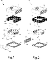
- FIG. 1 Perspective views of the elements incorporated in a first embodiment of an AF actuator 10 according to the present invention are shown in figures 1 (front view) and 2 (side view).
- the elements are vertically separated to allow their identification.
- the AF actuator 10 comprises a shield can 11, a housing 12, a return spring 13, two sets of rolling spheres 14, a movable lens carrier 15, a magnet 16, a shape memory alloy wire 17, two terminals 18, a bottom plate 19, a Flexible Printed Circuit board (FPC) 191, a Hall sensor 192.
- FPC Flexible Printed Circuit board
- the movable lens carrier 15 presents a frontal protrusion 20 for housing the shape memory alloy wire 17, in this case the protrusion has a lower apex 21 and the shape memory alloy wire 17 is held beneath it by the restraint action made by the two terminals 18, placed at a higher height (along the optical axis).
- Housing 12 and movable lens carrier 15 have side channels 100, 100', 101, 101' vertically aligned in pairs 100-101 and 100'-101' and defining two guide channels for holding the spheres 14. These elements have been indicated in the perspective views of figures 1 and 2 , and side channels 100-100' on housing 12 are well recognizable in the view from above (see following Fig.4 ).
- the AF structure shown in figures 1 and 2 comprises elements, such as a magnet 16 and a Hall sensor 192 for detecting the position of the movable lens carrier 15, that are entirely optional even though they are representative of the preferred embodiment of an AF actuator according to the present invention.
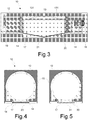
- Figure 3 shows a front see-through view of the assembled actuator 10 that comprises magnet 16 with an indication of its North-South polarity and a preferred configuration for the return spring 13, in the form of a leaf spring with rounded contact points 131 in order to exert a distributed force on the lens carrier 15.
- the actuator In the rest condition the actuator is in the so-called infinity focus position; when the shape memory alloy wire 17 is heated by current passage it shortens and exerts a force onto lens carrier 15 moving it upwards such that the lens is focused up to the so-called macro position (i.e. focusing on a nearby plane).
- the return elastic element 13 exerting a vertical return force opposing the SMA traction pushes back the lens carrier 15 to the infinity position.
- Infinity and macro represent the two AF extreme position and therefore correspond to the amount of adjustment that the AF actuator shall be capable to achieve.
- a position sensor and readout are also present to determine the correct equilibrium position during the AF actuator operation, also in this case exemplified by magnet 16 anchored to the lens carrier 15 and the Hall sensor 192 attached to the FPC board 191 ( figure 2 ).
- the FPC board will provide current to the SMA wire 17 through terminals 18 for its activation via Joule effect according to the Hall sensor readout.
- the return elastic means 13 exerts a force only in the vertical direction, and it is the geometry of the AF actuator that ensures the spheres alignment and confinement in the guide channels.
- the reciprocal configuration may be suitably employed, i.e. upper apex and lower terminals; in this case the return elastic element is beneath the lens carrier as the shape memory alloy wire will exert a downward traction (up-down direction defined with respect to the lowest element of the actuator, i.e. the bottom plate).
- the rest position corresponds to macro, while the fully activated position corresponds to infinity.
- Figure 4 shows a sectional view from above of the actuator depicted in figure 3
- figure 5 shows a preferred variant of the actuator in which the frontal protrusion 30 of the lens carrier 15 includes an apex 31 providing a slight offsetting, perpendicularly to the optical axis and radially outwards, between the shape memory alloy wire and the terminals, so that they do not to lie in a same vertical plane parallel to the optical axis.
- protrusion 30 is shaped such that the SMA wire follows a V-shaped path not only in the vertical plane ( Fig.3 ) but also in the horizontal plane ( Fig.5 ) so as to exert a traction, upon activation, not only in the up-down direction but also in the front-rear direction.
- the AF actuator according to the present invention is not restricted to a specific type of shape memory alloy wires, but any shape memory alloy wires activated by Joule effect may be usefully employed. Having said that, preferred is the use of shape memory alloy wires made with Ni-Ti alloys widely known in the field with the name of Nitinol, with diameters ranging from 10 ⁇ m to 50 ⁇ m and commercially available from a variety of sources, for examples the wires sold under the trade name Smartflex by SAES Getters S.p.A., of particular preference is the use of 25 ⁇ m wires.
- the material of the spheres there is no specific requirement apart from using a material with sufficient hardness, such as ceramic or metal (preferred stainless steel).
- a material with sufficient hardness such as ceramic or metal (preferred stainless steel).
- the number of spheres preferred is the use of the same number of spheres in each of the two guide channels, with a number of at least 2 spheres per channel. Preferably the number of spheres per channel is not higher than 5.
- the spheres diameter it is preferably comprised between 30 and 150 ⁇ m, most preferably comprised between 40 and 60 ⁇ m.
- an offsetting protrusion apex 31 moves the shape memory alloy wire median point far away from the optical axis by a distance comprised between 0,3 and 1 mm.
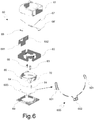
- a second embodiment 60 of an AF actuator according to the present invention is shown in the exploded view of figure 6 , with elements corresponding to the elements of the first embodiment that are indicated by correspondingly numbered references.
- the AF actuator 60 comprises a shield can 61, a housing 62, a return spring 63, two sets of rolling spheres 64, a movable lens carrier 65, a magnet 66, a shape memory alloy wire 67, two terminals 68, 68', a bottom plate 69 and a Flexible Printed Circuit board (FPC) 691 carrying a Hall sensor 692.
- FPC Flexible Printed Circuit board
- flexure 600 i.e. a thin element made of an elastic metallic material (e.g. steel, copper, bronze), arranged between the lens carrier 65 and the bottom plate 69.
- flexure 600 has a substantially semi-circular shape with end portions 601 that are bent over outwards and a middle portion 602 with a rectangular enlargement projecting outwards.
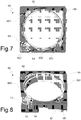
- Both the end and middle portions 601 and 602 include holes for connecting flexure 600 to housing 62 and lens carrier 65 respectively, as shown in figures 7 and 8 . More specifically, flexure 600 is connected to housing 62 through two pins 601' that are formed on the bottom thereof, close to the two corners adjacent to the lens carrier protrusion 70, and which engage corresponding holes formed in the end portions 601. Similarly, flexure 600 is also connected to the lens carrier 65 through a third connection point at the flexure middle portion 602, where a pair of holes allow the rectangular enlargement to be fitted on corresponding pins 602' formed on the bottom of the lens carrier protrusion 70.
- flexure 600 improves the stability of the AF actuator, such advantage being of particular relevance when the AF module is controlled via the Hall sensor and magnet distance.
- small lateral displacements due to rotation of the lens carrier 65 around the optical axis may induce feedback errors, and the presence of flexure 600 prevents such rotational displacements and improves the AF performances.
- the main difference between the first and second embodiment is the fact that in the former ( figures 1 and 2 ) the lens carrier protrusion apex 21 is essentially located in the middle of one of the housing faces, while in the latter ( figures 6 , 7 and 8 ) the lens carrier protrusion apex 71 is located at one of the corners of housing 62.
- a preferred variant of the above-described second embodiment envisions the presence of two additional guide channels in the two corners adjacent to the lens carrier protrusion for a total of four guide channels, each containing rolling spheres.
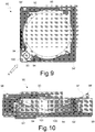
- This particular variant 90 is shown in figures 9 and 10 to have not only spheres 94 corresponding to spheres 64, i.e. arranged on the sides of the lens carrier protrusion 100, but also two other sets of spheres 94' (only two spheres per set in the illustrated example) that are located in opposite corner positions, always between housing 92 and the lens carrier 95.
- apex 71, 101 could also provide a slight offsetting of SMA wire 67, 97 perpendicularly to the optical axis and radially outwards, same as apex 31 in the variant of Fig.5 , so as to put spheres 64, 94 in the best operating condition.
- the invention consist in a control method for an AF actuator using spheres as an aid for the sliding of the lens carrier in the housing, and in particular in a control method comprising an initialization phase wherein the shape memory alloy wire is activated to move the lens carrier to a first end position, e.g. corresponding to the macro position, and then deactivated to move the lens carrier to a second end position, e.g. corresponding to the infinity position in the illustrated embodiments.
- This operation guarantees a reset of the AF actuator and ensures that the rolling spheres are in the best starting position.
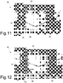
- Figures 11 and 12 show an enlarged detail of the AF actuator illustrated in figures 9 and 10 , with spheres 94 adjacent to the lens carrier protrusion 100 in the infinity position ( Fig. 11 ) and in the macro position ( Fig. 12 ).
- the end stop for the lower spheres of the sets is the bottom plate 99
- the end stop for the upper spheres is housing 92.
Landscapes
- Engineering & Computer Science (AREA)
- Physics & Mathematics (AREA)
- General Physics & Mathematics (AREA)
- Chemical & Material Sciences (AREA)
- Combustion & Propulsion (AREA)
- Mechanical Engineering (AREA)
- General Engineering & Computer Science (AREA)
- Optics & Photonics (AREA)
- Multimedia (AREA)
- Signal Processing (AREA)
- Lens Barrels (AREA)
Description
- The present invention is inherent to a novel and improved camera module autofocus (AF) actuator incorporating a shape memory alloy (SMA) wire as actuating element, with particular reference to cellular phones camera modules, and to a control method thereof.
- Generally speaking the use of shape memory alloy wires as actuating elements provides various advantages with respect to other actuating systems in terms of weight, power consumption, costs.
- These advantages have already been recognized also in the field of camera modules and have been the subject of various patent applications, such as international patent applications
WO 2007/113478 ,WO 2011/122438 andUS patent 8159762 , corresponding toUS 2011/0091193 A1 , all describing camera modules with a shape memory alloy wire in contact with the lens holder (sometimes referred in the field as lens barrel) and fixed to the camera module housing. The controlled heating via Joule effect of the shape memory alloy wire causes its contraction and the movement of the lens holder with respect to the housing. - The two above-referenced international patent applications do not address the frictional phenomena between housing and lens barrel and the related problems in terms of actuator lifetime, while this aspect is instead tagged in
US patent 8159762 by means of rolling members interposed between the housing and the barrel and an oblique return spring exerting a force with a component perpendicular to the optical axis to ensure the contact between the rolling members and the lens barrel. Even though this solution is an improvement in terms of frictional force management, this significant and constant perpendicular component causes itself a stress on the structure, and in frequently used actuating systems, such as in a camera module AF, it may lead to premature failures or to compensate by using upgraded components, for example by using wires bigger than required. On the other hand, the presence of this force component perpendicular to the optical axis is a prominent feature of this prior art actuator, to the point that it is contained in the characterizing portion of the independent claim ofUS 8159762 . Another drawback is associated to the manufacturing of such mechanical structures, as they cannot be made by adding the elements on top of each other but require the making and reciprocal coupling of sub-assemblies. - Purpose of the present invention is to overcome the drawback still present in the known art in terms of dealing with the frictional forces in a SMA-based autofocus actuator, and in a first aspect thereof consists in a camera module autofocus actuator as defined in independent claim 1 and comprising:
- a housing,
- a movable lens carrier having a protrusion with an apex for lodging a shape memory alloy wire,
- a shape memory alloy wire,
- at least four rolling spheres,
- a bottom plate,
- two electric terminals at a different height with respect to the protrusion apex,
- a return elastic element,
and in which camera module autofocus actuator - the bottom plate and the housing are fixed to each other, defining an autofocus main body,
- the two electric terminals are fixed onto the autofocus main body,
- the shape memory alloy wire is in contact with the lens carrier protrusion apex so as to exert a force on the movable lens carrier in a direction parallel to the optical axis thereof and its extremities are locked to the two electric terminals on the autofocus main body,
- the housing and the movable lens carrier are aligned via at least two side channels defining at least two guide channels containing and holding the rolling spheres,
- the return elastic element is mounted between the housing and the lens carrier,
- The invention in a second aspect consists in a control method for a camera module autofocus actuator as defined in
independent claim 14. - As per above description, the two electric terminals are fixed and held to the main body (housing + bottom plate) and therefore these elements may be equivalently fixed onto the housing or onto the bottom plate, notwithstanding the requirement of being at a different height with respect to the lens carrier protrusion apex.
- One of the most common variants for a camera module AF actuator according to the present invention envisions the presence of a Flexible Printed Circuit board (FPC) that jointly with a magnet and a Hall sensor provides information about the lens carrier displacement and position. It is to be underlined that such elements are optional, since other equivalent technical solutions may be employed, such as a resistance feedback of the shape memory alloy, as described for example in the international patent application number
WO 2008/099156 . - The invention will be further illustrated with the help of the following figures, where:
-
Figures 1 and 2 are vertically exploded perspective views of the elements constituting an AF actuator according to a first embodiment of the present invention; -
Figure 3 is a front see-through view of the AF actuator offigures 1 and 2 in the assembled condition; -
Figure 4 is a sectional view from above of the AF actuator offigure 3 ; -
Figure 5 is a sectional view from above of a preferred variant for the AF actuator offigure 3 ; -
Figure 6 is a vertically exploded perspective view of the elements constituting an AF actuator according to a second embodiment of the present invention, with an enlarged detail of one of said elements; -
Figure 7 is a bottom view of the AF actuator offigure 6 , without the top and bottom elements, in the assembled condition; -
Figure 8 is a bottom perspective view of the AF actuator offigure 7 ; -
Figure 9 is a top view of a preferred variant for the AF actuator offigure 7 ; -
Figure 10 is a see-through view of the AF actuator offigure 9 along the direction of arrow A; and -
Figures 11 and 12 are enlarged partial views of the AF actuator offigure 9 along the direction of arrow A, showing the detail of the rolling members in the two extreme AF actuator positions. - In the above figures the dimensions and dimensional ratio of the elements may not be correct and in some cases, such as for example with regards to the shape memory alloy wire diameter, have been altered in order to enhance the drawing comprehension.
- Perspective views of the elements incorporated in a first embodiment of an
AF actuator 10 according to the present invention are shown infigures 1 (front view) and 2 (side view). In this representation the elements are vertically separated to allow their identification. In particular theAF actuator 10 comprises a shield can 11, ahousing 12, areturn spring 13, two sets ofrolling spheres 14, amovable lens carrier 15, amagnet 16, a shapememory alloy wire 17, twoterminals 18, abottom plate 19, a Flexible Printed Circuit board (FPC) 191, aHall sensor 192. - The
movable lens carrier 15 presents afrontal protrusion 20 for housing the shapememory alloy wire 17, in this case the protrusion has alower apex 21 and the shapememory alloy wire 17 is held beneath it by the restraint action made by the twoterminals 18, placed at a higher height (along the optical axis). A variant envisions the use of an upper apex with the shape memory alloy wire held above it and the terminals placed at a lower height. -
Housing 12 andmovable lens carrier 15 haveside channels spheres 14. These elements have been indicated in the perspective views offigures 1 and 2 , and side channels 100-100' onhousing 12 are well recognizable in the view from above (see followingFig.4 ). - The AF structure shown in
figures 1 and 2 comprises elements, such as amagnet 16 and aHall sensor 192 for detecting the position of themovable lens carrier 15, that are entirely optional even though they are representative of the preferred embodiment of an AF actuator according to the present invention. -
Figure 3 shows a front see-through view of the assembledactuator 10 that comprisesmagnet 16 with an indication of its North-South polarity and a preferred configuration for thereturn spring 13, in the form of a leaf spring withrounded contact points 131 in order to exert a distributed force on thelens carrier 15. - In the rest condition the actuator is in the so-called infinity focus position; when the shape
memory alloy wire 17 is heated by current passage it shortens and exerts a force ontolens carrier 15 moving it upwards such that the lens is focused up to the so-called macro position (i.e. focusing on a nearby plane). When the current supply stops, the returnelastic element 13 exerting a vertical return force opposing the SMA traction pushes back thelens carrier 15 to the infinity position. Infinity and macro represent the two AF extreme position and therefore correspond to the amount of adjustment that the AF actuator shall be capable to achieve. - A position sensor and readout are also present to determine the correct equilibrium position during the AF actuator operation, also in this case exemplified by
magnet 16 anchored to thelens carrier 15 and theHall sensor 192 attached to the FPC board 191 (figure 2 ). The FPC board will provide current to theSMA wire 17 throughterminals 18 for its activation via Joule effect according to the Hall sensor readout. - It is important to underline that with the AF actuator configuration according to the first embodiment of the present invention the return elastic means 13 exerts a force only in the vertical direction, and it is the geometry of the AF actuator that ensures the spheres alignment and confinement in the guide channels.
- As mentioned with regards to
figures 1 and 2 , also the reciprocal configuration may be suitably employed, i.e. upper apex and lower terminals; in this case the return elastic element is beneath the lens carrier as the shape memory alloy wire will exert a downward traction (up-down direction defined with respect to the lowest element of the actuator, i.e. the bottom plate). In this case the rest position corresponds to macro, while the fully activated position corresponds to infinity. -
Figure 4 shows a sectional view from above of the actuator depicted infigure 3 , whilefigure 5 shows a preferred variant of the actuator in which thefrontal protrusion 30 of thelens carrier 15 includes anapex 31 providing a slight offsetting, perpendicularly to the optical axis and radially outwards, between the shape memory alloy wire and the terminals, so that they do not to lie in a same vertical plane parallel to the optical axis. In other words,protrusion 30 is shaped such that the SMA wire follows a V-shaped path not only in the vertical plane (Fig.3 ) but also in the horizontal plane (Fig.5 ) so as to exert a traction, upon activation, not only in the up-down direction but also in the front-rear direction. - With such a horizontal angle the
rolling spheres 14 will be put in the best operating condition and subjected also to a minimal orthogonal (with respect to the optical axis) force. This configuration to a certain extent and by an operative standpoint is the opposite with respect to the one shown in the above-referenced patentUS 8159762 as in this case it is the SMA wire that exerts the force in the direction orthogonal to the optical axis and not the return spring. Moreover, such an orthogonal component is minimal and exerted only when needed, i.e. during the AF activation, and not permanently as in the case of a transversal pulling by the elastic return means in the prior art. - The AF actuator according to the present invention is not restricted to a specific type of shape memory alloy wires, but any shape memory alloy wires activated by Joule effect may be usefully employed. Having said that, preferred is the use of shape memory alloy wires made with Ni-Ti alloys widely known in the field with the name of Nitinol, with diameters ranging from 10 µm to 50 µm and commercially available from a variety of sources, for examples the wires sold under the trade name Smartflex by SAES Getters S.p.A., of particular preference is the use of 25 µm wires.
- With regards to the material of the spheres, there is no specific requirement apart from using a material with sufficient hardness, such as ceramic or metal (preferred stainless steel). As to the number of spheres, preferred is the use of the same number of spheres in each of the two guide channels, with a number of at least 2 spheres per channel. Preferably the number of spheres per channel is not higher than 5.
- With regards to the spheres diameter, it is preferably comprised between 30 and 150 µm, most preferably comprised between 40 and 60 µm.
- In the embodiment envisioning the use of an offsetting
protrusion apex 31, the latter moves the shape memory alloy wire median point far away from the optical axis by a distance comprised between 0,3 and 1 mm. - A
second embodiment 60 of an AF actuator according to the present invention is shown in the exploded view offigure 6 , with elements corresponding to the elements of the first embodiment that are indicated by correspondingly numbered references. In particular theAF actuator 60 comprises a shield can 61, ahousing 62, areturn spring 63, two sets of rollingspheres 64, amovable lens carrier 65, amagnet 66, a shapememory alloy wire 67, twoterminals 68, 68', abottom plate 69 and a Flexible Printed Circuit board (FPC) 691 carrying aHall sensor 692. - Some of the distinguishing features of this embodiment with respect to the embodiment shown in
figures 1 and 2 are in particular the shape ofhousing 62 and of thelens carrier 65, withterminals 68, 68' connected onto two adjacent faces thereof and aprotrusion 70 formed on thelens carrier 65 in correspondence with a corner ofhousing 62. Similarly, as clearly shown infigures 7 and 8 , the guide channels for holding thespheres 64 are formed on the sides of thecorner protrusion 70, which is also provided with an apex 71 for holding theSMA wire 67. - Another difference in this second embodiment is the presence of a so-called
flexure 600, i.e. a thin element made of an elastic metallic material (e.g. steel, copper, bronze), arranged between thelens carrier 65 and thebottom plate 69. As better shown in the enlarged detail ofFig.6 ,flexure 600 has a substantially semi-circular shape withend portions 601 that are bent over outwards and amiddle portion 602 with a rectangular enlargement projecting outwards. - Both the end and
middle portions flexure 600 tohousing 62 andlens carrier 65 respectively, as shown infigures 7 and 8 . More specifically,flexure 600 is connected tohousing 62 through two pins 601' that are formed on the bottom thereof, close to the two corners adjacent to thelens carrier protrusion 70, and which engage corresponding holes formed in theend portions 601. Similarly,flexure 600 is also connected to thelens carrier 65 through a third connection point at the flexuremiddle portion 602, where a pair of holes allow the rectangular enlargement to be fitted on corresponding pins 602' formed on the bottom of thelens carrier protrusion 70. - More details on the flexure and its presence in an AF module controlled by a shape memory alloy wire can be found in the above-mentioned international patent application
WO 2007/113478 . Generally speaking,flexure 600 improves the stability of the AF actuator, such advantage being of particular relevance when the AF module is controlled via the Hall sensor and magnet distance. In fact, small lateral displacements due to rotation of thelens carrier 65 around the optical axis may induce feedback errors, and the presence offlexure 600 prevents such rotational displacements and improves the AF performances. - Apart from the presence of the flexure, which is anyway an optional element, the main difference between the first and second embodiment is the fact that in the former (
figures 1 and 2 ) the lenscarrier protrusion apex 21 is essentially located in the middle of one of the housing faces, while in the latter (figures 6 ,7 and 8 ) the lenscarrier protrusion apex 71 is located at one of the corners ofhousing 62. - A preferred variant of the above-described second embodiment, again with corresponding elements indicated by correspondingly numbered references, envisions the presence of two additional guide channels in the two corners adjacent to the lens carrier protrusion for a total of four guide channels, each containing rolling spheres. This
particular variant 90 is shown infigures 9 and 10 to have not onlyspheres 94 corresponding tospheres 64, i.e. arranged on the sides of thelens carrier protrusion 100, but also two other sets of spheres 94' (only two spheres per set in the illustrated example) that are located in opposite corner positions, always betweenhousing 92 and thelens carrier 95. - These
spheres 94, 94' are also shown in the see-through view offigure 10 that shows also the lenscarrier protrusion apex 101 and the shapememory alloy wire 97 connected toterminals 98, 98' located on two opposite corners ofhousing 92, as well as thereturn spring 93 received within thecorner protrusion 100. It is to be underlined that the variant shown infigures 9 and 10 is characterized by the spheres locations, whereas the number of spheres per location as depicted and shown in the figures is merely indicative. - It should be noted that
apex SMA wire apex 31 in the variant ofFig.5 , so as to putspheres - In a second aspect thereof the invention consist in a control method for an AF actuator using spheres as an aid for the sliding of the lens carrier in the housing, and in particular in a control method comprising an initialization phase wherein the shape memory alloy wire is activated to move the lens carrier to a first end position, e.g. corresponding to the macro position, and then deactivated to move the lens carrier to a second end position, e.g. corresponding to the infinity position in the illustrated embodiments.
- This operation guarantees a reset of the AF actuator and ensures that the rolling spheres are in the best starting position.
-
Figures 11 and 12 show an enlarged detail of the AF actuator illustrated infigures 9 and 10 , withspheres 94 adjacent to thelens carrier protrusion 100 in the infinity position (Fig. 11 ) and in the macro position (Fig. 12 ). Infigure 11 the end stop for the lower spheres of the sets is thebottom plate 99, whereas infigure 12 the end stop for the upper spheres ishousing 92.
Claims (16)
- A camera module autofocus actuator (10; 60; 90) comprising:- a housing (12; 62; 92),- a movable lens carrier (15; 65; 95) having a protrusion (20; 70; 100) with an apex (21; 71; 101) for lodging a shape memory alloy wire (17; 67; 97),- a shape memory alloy wire (17; 67; 97),- at least four rolling spheres (14; 64; 94, 94'),- a bottom plate (19; 69; 99)- two electric terminals (18; 68, 68'; 98, 98') at a different height with respect to said protrusion apex (21; 71; 101),- a return elastic element (13; 63; 93),and in which camera module autofocus actuator (10; 60; 90):- said bottom plate (19; 69; 99) and said housing (12; 62; 92) are fixed to each other, defining an autofocus main body,- said two electric terminals (18; 68, 68'; 98, 98') are fixed onto said autofocus main body,- said shape memory alloy wire (17; 67; 97) is in contact with the lens carrier protrusion apex (21; 71; 101) so as to exert a force on the movable lens carrier (15; 65; 95) in a direction parallel to the optical axis thereof, and its extremities are locked to the two electric terminals (18; 68, 68'; 98, 98') on the autofocus main body,- the housing (12; 62; 92) and said movable lens carrier (15; 65; 95) are aligned via at least two side channels (100, 100'; 101, 101') defining at least two guide channels containing and holding said rolling spheres (14; 64; 94, 94'),- said return elastic element (13; 63; 93) is mounted between the housing (12; 62; 92) and the lens carrier (15; 65; 95),characterized in that the return elastic element (13; 63; 93) exerts a force on the movable lens carrier (15; 65; 95) only in a direction parallel to the optical axis thereof, opposing the force of the shape memory alloy wire (17; 67; 97) on the movable lens carrier (15; 65; 95).
- A camera module autofocus actuator (10) according to claim 1, wherein said two electric terminals (18) are located on the same face of the autofocus main body.
- A camera module autofocus actuator (60; 90) according to claim 1, wherein said two electric terminals (68, 68'; 98, 98') are located on two adjacent faces of the autofocus main body.
- A camera module autofocus actuator (10; 60) according to any of the previous claims, wherein the number of guide channels is two.
- A camera module autofocus actuator (90) according to any of claims 1 to 3, wherein the number of guide channels is four.
- A camera module autofocus actuator (10; 60; 90) according to any of the previous claims, further comprising a flexure (600) located between the housing (12; 62; 92) and the movable lens carrier (15; 65; 95).
- A camera module autofocus actuator (10; 60; 90) according to any of the previous claims, wherein the number of spheres (14; 64; 94, 94') per guide channel is not higher than 5 and not lower than 2.
- A camera module autofocus actuator (10; 60; 90) according to any of the previous claims, wherein the spheres (14; 64; 94, 94') have a diameter comprised between 30 and 150 µm, preferably between 40 and 60 µm.
- A camera module autofocus actuator (10) according to any of the previous claims, wherein the return elastic element is a leaf spring (13).
- A camera module autofocus actuator (10) according to claim 9, wherein said leaf spring (13) has rounded contact points (131).
- A camera module autofocus actuator (10; 60; 90) according to any of the previous claims, further comprising a magnet (16; 66) fixed onto the movable lens carrier (15; 65; 95) and a Hall sensor (192; 692) fixed onto a Flexible Printed Circuit board (191; 691) fixed to the housing (12; 62; 92).
- A camera module autofocus actuator (10; 60; 90) according to any of the previous claims, wherein the shape memory alloy wire (17; 67; 97) is made of a Ni-Ti alloy and has a diameter comprised between 10 and 50 µm.
- A camera module autofocus actuator (10; 60; 90) according to any of the previous claims, wherein the movable lens carrier (15; 65; 95) has a protrusion (30; 70; 100) with an apex (31; 71; 101) that provides a slight offsetting perpendicularly to the optical axis and radially outwards, thus moving the shape memory alloy wire median point far away from the optical axis by a distance comprised between 0,3 mm and 1 mm.
- Control method for a camera module autofocus actuator (10; 60; 90) according to any of the previous claims, comprising an initialization phase wherein the shape memory alloy wire (17; 67; 97) is activated to move the movable lens carrier (15; 65; 95) to a first end position and then deactivated to move the lens carrier (15; 65; 95) to a second end position by means of the return elastic element (13; 63; 93).
- Control method according to claim 14, wherein the position of the lens carrier (15; 65; 95) is determined by a Flexible Printed Circuit board (191; 691) via a Hall sensor (192; 692) and a magnet (16; 66).
- Control method according to claim 14, wherein the position of the lens carrier (15; 65; 95) is determined by a resistance measurement of the shape memory alloy wire (17; 67; 97).
Applications Claiming Priority (3)
| Application Number | Priority Date | Filing Date | Title |
|---|---|---|---|
| ITMI2014A001945A ITMI20141945A1 (en) | 2014-11-12 | 2014-11-12 | CAMERA MODULE ACTUATOR FOR AUTO-FOCUS |
| ITMI20150007 | 2015-01-09 | ||
| PCT/IB2015/058633 WO2016075606A1 (en) | 2014-11-12 | 2015-11-09 | Camera module autofocus actuator and control method thereof |
Publications (2)
| Publication Number | Publication Date |
|---|---|
| EP3210078A1 EP3210078A1 (en) | 2017-08-30 |
| EP3210078B1 true EP3210078B1 (en) | 2018-09-05 |
Family
ID=54697620
Family Applications (1)
| Application Number | Title | Priority Date | Filing Date |
|---|---|---|---|
| EP15798570.6A Active EP3210078B1 (en) | 2014-11-12 | 2015-11-09 | Camera module autofocus actuator and control method thereof |
Country Status (7)
| Country | Link |
|---|---|
| US (1) | US10114272B2 (en) |
| EP (1) | EP3210078B1 (en) |
| JP (1) | JP2017535808A (en) |
| KR (1) | KR102249681B1 (en) |
| CN (1) | CN107111212B (en) |
| TW (1) | TWI651562B (en) |
| WO (1) | WO2016075606A1 (en) |
Families Citing this family (36)
| Publication number | Priority date | Publication date | Assignee | Title |
|---|---|---|---|---|
| TWI618949B (en) * | 2016-04-01 | 2018-03-21 | 台灣東電化股份有限公司 | Lens driving mechanism and control method thereof |
| CN109416498B (en) * | 2016-08-08 | 2022-03-22 | 剑桥机电有限公司 | Dual camera apparatus |
| IT201700048138A1 (en) * | 2017-05-04 | 2018-11-04 | Actuator Solutions GmbH | Camera module auto-focus actuator |
| IT201700074728A1 (en) * | 2017-07-04 | 2019-01-04 | Actuator Solutions GmbH | Camera module auto-focus actuator |
| US10791514B2 (en) * | 2017-08-22 | 2020-09-29 | Avago Technologies International Sales Pte. Limited | Neighbor awareness networking tethering |
| GB201721716D0 (en) * | 2017-12-22 | 2018-02-07 | Cambridge Mechatronics Ltd | Sma actuator |
| US10809524B2 (en) | 2018-01-08 | 2020-10-20 | Facebook Technologies, Llc | Varifocal apparatuses, systems, and methods employing a deformable stepped lens |
| CN110032024B (en) * | 2018-01-12 | 2024-02-02 | 宁波舜宇光电信息有限公司 | Optical actuator, and corresponding camera module and camera module array |
| GB2608572B (en) * | 2018-01-22 | 2023-07-19 | Cambridge Mechatronics Ltd | Shape memory alloy actuation apparatus |
| EP3514602A1 (en) | 2018-01-23 | 2019-07-24 | Universitatea Stefan cel Mare Suceava - Romania | Microscope lens with automatic focus |
| CN108318992A (en) * | 2018-04-13 | 2018-07-24 | 湖南新视电子技术有限公司 | A kind of camera Miniature drive motor |
| CN108303779A (en) * | 2018-04-13 | 2018-07-20 | 湖南新视电子技术有限公司 | A kind of camera lens holder assembly suitable for webcam driver motor |
| WO2019216590A1 (en) * | 2018-05-11 | 2019-11-14 | Lg Electronics Inc. | Camera for electronic device |
| IT201800006584A1 (en) | 2018-06-22 | 2019-12-22 | Oscillating actuator in shape memory alloy | |
| KR102584971B1 (en) | 2018-07-06 | 2023-10-05 | 삼성전기주식회사 | Camera module |
| KR102585027B1 (en) * | 2018-08-16 | 2023-10-06 | 엘지이노텍 주식회사 | Lens Actuator and Camera module including the same |
| US11019266B1 (en) | 2018-08-31 | 2021-05-25 | Apple Inc. | Blunting optical suspension springs for particle reduction |
| KR20200045359A (en) | 2018-10-22 | 2020-05-04 | 삼성전자주식회사 | See-through display device |
| GB201820383D0 (en) * | 2018-12-14 | 2019-01-30 | Cambridge Mechatronics Ltd | Zero power hold SMA Actuator assembly |
| IT201900003589A1 (en) * | 2019-03-12 | 2020-09-12 | Actuator Solutions GmbH | Multi-stable actuator based on shape memory alloy wires |
| JP6814245B2 (en) * | 2019-04-12 | 2021-01-13 | エーエーシー オプティクス (チャンジョウ)カンパニーリミテッド | Optical element drive, camera and portable electronic equipment |
| CN111856692B (en) * | 2019-04-26 | 2022-07-05 | 台湾东电化股份有限公司 | Lens automatic focusing driving device |
| JP7097664B2 (en) * | 2019-06-01 | 2022-07-08 | エーエーシー オプティックス ソリューションズ ピーティーイー リミテッド | Autofocus lens unit |
| WO2020243859A1 (en) * | 2019-06-01 | 2020-12-10 | 瑞声光学解决方案私人有限公司 | Automatic focusing lens assembly and automatic focusing method thereof |
| JP7189852B2 (en) * | 2019-09-11 | 2022-12-14 | 新思考電機有限公司 | Lens driving device, camera device and electronic device |
| CN111175964B (en) * | 2019-12-12 | 2025-08-22 | 河南皓泽电子股份有限公司昆山分公司 | Liquid lens focus and anti-shake devices, camera modules and electronic devices |
| CN111641761B (en) * | 2020-05-27 | 2022-04-29 | 维沃移动通信有限公司 | Camera module and electronic equipment |
| CN112698468A (en) * | 2021-01-14 | 2021-04-23 | 东莞市亚登电子有限公司 | Lens module |
| CN112684566A (en) * | 2021-01-20 | 2021-04-20 | 东莞市亚登电子有限公司 | Lens module and camera equipment with same |
| DE102021111384A1 (en) * | 2021-05-03 | 2022-11-03 | Schock Gmbh | Curable casting compound, molded body made from it and method for producing the molded body |
| KR20230020160A (en) * | 2021-08-03 | 2023-02-10 | 엘지이노텍 주식회사 | A camera device and optical instrument including the same |
| CN116009177A (en) * | 2021-10-22 | 2023-04-25 | 台湾东电化股份有限公司 | Optical element drive mechanism |
| CN115037878A (en) * | 2022-06-27 | 2022-09-09 | 北京可利尔福科技有限公司 | Focus actuators, optical modules and terminal equipment for optical devices |
| CN115542496A (en) * | 2022-09-15 | 2022-12-30 | 北京可利尔福科技有限公司 | Optical device drive mechanism, optical module and mobile terminal |
| CN115963673B (en) * | 2023-01-06 | 2024-07-19 | 上海信迈电子科技有限公司 | Anti-shake structure, camera device and electronic equipment |
| KR20240156116A (en) * | 2023-04-21 | 2024-10-29 | 자화전자(주) | Actuator for camera with elastic member |
Family Cites Families (37)
| Publication number | Priority date | Publication date | Assignee | Title |
|---|---|---|---|---|
| US6891627B1 (en) * | 2000-09-20 | 2005-05-10 | Kla-Tencor Technologies Corp. | Methods and systems for determining a critical dimension and overlay of a specimen |
| JP4303116B2 (en) * | 2001-11-21 | 2009-07-29 | アイサイエンス コーポレイション | Ophthalmic microsurgery device |
| JP2003178409A (en) * | 2001-12-13 | 2003-06-27 | Matsushita Electric Ind Co Ltd | Rotary drum device |
| JP4055938B2 (en) * | 2002-04-18 | 2008-03-05 | ミネベア株式会社 | Radial ball bearing retainer |
| JP4413770B2 (en) * | 2003-12-25 | 2010-02-10 | Hoya株式会社 | Lens barrel |
| JP2005227715A (en) * | 2004-02-16 | 2005-08-25 | Sony Corp | Lens unit adapter device and imaging device |
| KR100617828B1 (en) * | 2004-08-23 | 2006-08-28 | 삼성전자주식회사 | Optical zoom device and mobile communication device using the same |
| GB0606425D0 (en) * | 2006-03-30 | 2006-05-10 | 1 Ltd | Camera lens actuation apparatus |
| KR101353158B1 (en) | 2006-03-30 | 2014-01-22 | 캠브리지 메카트로닉스 리미티드 | Camera lens actuation apparatus |
| WO2008099156A2 (en) | 2007-02-12 | 2008-08-21 | Cambridge Mechatronics Limited | Shape memory alloy actuation apparatus |
| WO2008099155A1 (en) | 2007-02-12 | 2008-08-21 | Cambridge Mechatronics Limited | Shape memory alloy actuation apparatus |
| JP4981547B2 (en) * | 2007-06-28 | 2012-07-25 | オリンパスイメージング株式会社 | Driving device and imaging device |
| JP2009060768A (en) * | 2007-09-03 | 2009-03-19 | Nikon Corp | Actuator, lens barrel, camera |
| EP2239610A1 (en) * | 2008-01-30 | 2010-10-13 | Seiko Instruments Inc. | Drive module, and electronic device having the same |
| EP2375069A1 (en) * | 2008-12-24 | 2011-10-12 | Konica Minolta Opto, Inc. | Shape memory alloy actuator drive device and method, and imaging device using same |
| JP2010277067A (en) * | 2009-04-28 | 2010-12-09 | Mitsumi Electric Co Ltd | Lens drive device |
| KR101044219B1 (en) * | 2009-10-19 | 2011-06-29 | 삼성전기주식회사 | Lens drive module |
| JP5211015B2 (en) | 2009-11-04 | 2013-06-12 | 日立マクセル株式会社 | Imaging device |
| JP2011209468A (en) | 2010-03-29 | 2011-10-20 | Seiko Instruments Inc | Drive module, electronic device and drive module control method |
| ES2880840T3 (en) * | 2010-05-06 | 2021-11-25 | Immunolight Llc | Adhesive bonding composition and method of use |
| US8320756B2 (en) * | 2010-08-10 | 2012-11-27 | Digital Imaging Systems Gmbh | Single actuator configuration for a camera module |
| JP5689630B2 (en) * | 2010-09-01 | 2015-03-25 | 日本電産サンキョー株式会社 | Optical apparatus for photographing and optical system for photographing |
| JP2012105201A (en) * | 2010-11-12 | 2012-05-31 | Seiko Instruments Inc | Driving module and electronic device |
| JP2012137668A (en) * | 2010-12-27 | 2012-07-19 | Seiko Instruments Inc | Drive module, electronics and control method of drive module |
| JP2013025259A (en) * | 2011-07-25 | 2013-02-04 | Hoya Corp | Position control device of retreating optical element |
| KR101281299B1 (en) | 2011-07-13 | 2013-07-03 | 엘지이노텍 주식회사 | Camera module |
| KR101314652B1 (en) * | 2012-03-30 | 2013-10-07 | 자화전자(주) | Controlling apparatus for operating camera module and method thereof |
| US8743473B2 (en) * | 2012-05-04 | 2014-06-03 | Tdk Taiwan Corporation | Miniature lens auto-focusing structure |
| US9307128B2 (en) * | 2012-06-26 | 2016-04-05 | Alex Ning | Lens mount |
| JP2014010380A (en) * | 2012-07-02 | 2014-01-20 | Panasonic Corp | Lens actuator |
| CN103529536B (en) * | 2012-07-06 | 2018-05-08 | 河南省酷美智能科技有限公司 | Actuator and camera module with same |
| JP5970304B2 (en) * | 2012-09-05 | 2016-08-17 | Hoya株式会社 | Optical means support structure |
| KR101340608B1 (en) | 2012-11-12 | 2013-12-10 | (주)옵티스 | Camera module |
| CN103837958A (en) * | 2012-11-23 | 2014-06-04 | 鸿富锦精密工业(深圳)有限公司 | Actuator and camera module provided with actuator |
| KR101753444B1 (en) * | 2013-04-10 | 2017-07-03 | 엘지이노텍 주식회사 | Camera module |
| US9310584B2 (en) * | 2013-09-11 | 2016-04-12 | Sunming Technologies (Hk) Limited | Lens driving apparatus |
| KR102494346B1 (en) * | 2015-04-10 | 2023-02-01 | 삼성전기주식회사 | Lens driving device and camera module including same |
-
2015
- 2015-11-09 CN CN201580055001.9A patent/CN107111212B/en active Active
- 2015-11-09 KR KR1020177009487A patent/KR102249681B1/en active Active
- 2015-11-09 WO PCT/IB2015/058633 patent/WO2016075606A1/en not_active Ceased
- 2015-11-09 US US15/516,345 patent/US10114272B2/en active Active
- 2015-11-09 JP JP2017519481A patent/JP2017535808A/en active Pending
- 2015-11-09 EP EP15798570.6A patent/EP3210078B1/en active Active
- 2015-11-10 TW TW104137023A patent/TWI651562B/en active
Also Published As
| Publication number | Publication date |
|---|---|
| TWI651562B (en) | 2019-02-21 |
| JP2017535808A (en) | 2017-11-30 |
| KR20170082509A (en) | 2017-07-14 |
| US10114272B2 (en) | 2018-10-30 |
| TW201632934A (en) | 2016-09-16 |
| EP3210078A1 (en) | 2017-08-30 |
| US20170299945A1 (en) | 2017-10-19 |
| KR102249681B1 (en) | 2021-05-10 |
| WO2016075606A1 (en) | 2016-05-19 |
| CN107111212B (en) | 2019-11-12 |
| CN107111212A (en) | 2017-08-29 |
Similar Documents
| Publication | Publication Date | Title |
|---|---|---|
| US10114272B2 (en) | Camera module autofocus actuator and control method thereof | |
| US10901173B2 (en) | Camera module autofocus actuator | |
| EP3619576B1 (en) | Camera module autofocus actuator | |
| US8073320B2 (en) | Shape memory alloy actuation apparatus | |
| EP3497517B1 (en) | Optical image stabilizer | |
| CN115427679A (en) | Actuator assembly | |
| CN107085275B (en) | Lens driving device | |
| KR101569345B1 (en) | Actuator Using Shape Memory Alloy Wire | |
| CN112236596A (en) | shape memory alloy actuator | |
| CN222415098U (en) | Actuator assembly and camera module | |
| CN110262158A (en) | autofocus lens assembly | |
| KR20140083942A (en) | Auto focusing apparatus for micro camera module | |
| JPWO2010098340A1 (en) | Driving device and lens driving device | |
| CN106019524A (en) | Lens driving device | |
| ITMI20141945A1 (en) | CAMERA MODULE ACTUATOR FOR AUTO-FOCUS | |
| CN211180495U (en) | Actuator device, image pickup unit, and electronic apparatus | |
| JP2017122943A (en) | Camera module drive mechanism and leaf spring for camera module drive mechanism | |
| JP2013222051A (en) | Camera module driving mechanism and leaf spring for camera module driving mechanism | |
| WO2018225948A1 (en) | Camera device having easy-to-assemble integrated plate spring structure |
Legal Events
| Date | Code | Title | Description |
|---|---|---|---|
| PUAI | Public reference made under article 153(3) epc to a published international application that has entered the european phase |
Free format text: ORIGINAL CODE: 0009012 |
|
| 17P | Request for examination filed |
Effective date: 20170522 |
|
| AK | Designated contracting states |
Kind code of ref document: A1 Designated state(s): AL AT BE BG CH CY CZ DE DK EE ES FI FR GB GR HR HU IE IS IT LI LT LU LV MC MK MT NL NO PL PT RO RS SE SI SK SM TR |
|
| AX | Request for extension of the european patent |
Extension state: BA ME |
|
| GRAP | Despatch of communication of intention to grant a patent |
Free format text: ORIGINAL CODE: EPIDOSNIGR1 |
|
| DAV | Request for validation of the european patent (deleted) | ||
| DAX | Request for extension of the european patent (deleted) | ||
| INTG | Intention to grant announced |
Effective date: 20171103 |
|
| GRAJ | Information related to disapproval of communication of intention to grant by the applicant or resumption of examination proceedings by the epo deleted |
Free format text: ORIGINAL CODE: EPIDOSDIGR1 |
|
| REG | Reference to a national code |
Ref country code: DE Ref legal event code: R079 Ref document number: 602015015865 Country of ref document: DE Free format text: PREVIOUS MAIN CLASS: G03B0017020000 Ipc: F03G0007060000 |
|
| INTC | Intention to grant announced (deleted) | ||
| RIC1 | Information provided on ipc code assigned before grant |
Ipc: F03G 7/06 20060101AFI20180207BHEP Ipc: G03B 13/36 20060101ALI20180207BHEP Ipc: G03B 17/02 20060101ALI20180207BHEP |
|
| GRAP | Despatch of communication of intention to grant a patent |
Free format text: ORIGINAL CODE: EPIDOSNIGR1 |
|
| INTG | Intention to grant announced |
Effective date: 20180508 |
|
| GRAS | Grant fee paid |
Free format text: ORIGINAL CODE: EPIDOSNIGR3 |
|
| GRAA | (expected) grant |
Free format text: ORIGINAL CODE: 0009210 |
|
| AK | Designated contracting states |
Kind code of ref document: B1 Designated state(s): AL AT BE BG CH CY CZ DE DK EE ES FI FR GB GR HR HU IE IS IT LI LT LU LV MC MK MT NL NO PL PT RO RS SE SI SK SM TR |
|
| REG | Reference to a national code |
Ref country code: GB Ref legal event code: FG4D |
|
| REG | Reference to a national code |
Ref country code: CH Ref legal event code: EP |
|
| REG | Reference to a national code |
Ref country code: AT Ref legal event code: REF Ref document number: 1038124 Country of ref document: AT Kind code of ref document: T Effective date: 20180915 |
|
| REG | Reference to a national code |
Ref country code: IE Ref legal event code: FG4D |
|
| REG | Reference to a national code |
Ref country code: DE Ref legal event code: R096 Ref document number: 602015015865 Country of ref document: DE |
|
| REG | Reference to a national code |
Ref country code: NL Ref legal event code: MP Effective date: 20180905 |
|
| REG | Reference to a national code |
Ref country code: LT Ref legal event code: MG4D |
|
| PG25 | Lapsed in a contracting state [announced via postgrant information from national office to epo] |
Ref country code: FI Free format text: LAPSE BECAUSE OF FAILURE TO SUBMIT A TRANSLATION OF THE DESCRIPTION OR TO PAY THE FEE WITHIN THE PRESCRIBED TIME-LIMIT Effective date: 20180905 Ref country code: NO Free format text: LAPSE BECAUSE OF FAILURE TO SUBMIT A TRANSLATION OF THE DESCRIPTION OR TO PAY THE FEE WITHIN THE PRESCRIBED TIME-LIMIT Effective date: 20181205 Ref country code: RS Free format text: LAPSE BECAUSE OF FAILURE TO SUBMIT A TRANSLATION OF THE DESCRIPTION OR TO PAY THE FEE WITHIN THE PRESCRIBED TIME-LIMIT Effective date: 20180905 Ref country code: GR Free format text: LAPSE BECAUSE OF FAILURE TO SUBMIT A TRANSLATION OF THE DESCRIPTION OR TO PAY THE FEE WITHIN THE PRESCRIBED TIME-LIMIT Effective date: 20181206 Ref country code: BG Free format text: LAPSE BECAUSE OF FAILURE TO SUBMIT A TRANSLATION OF THE DESCRIPTION OR TO PAY THE FEE WITHIN THE PRESCRIBED TIME-LIMIT Effective date: 20181205 Ref country code: SE Free format text: LAPSE BECAUSE OF FAILURE TO SUBMIT A TRANSLATION OF THE DESCRIPTION OR TO PAY THE FEE WITHIN THE PRESCRIBED TIME-LIMIT Effective date: 20180905 Ref country code: LT Free format text: LAPSE BECAUSE OF FAILURE TO SUBMIT A TRANSLATION OF THE DESCRIPTION OR TO PAY THE FEE WITHIN THE PRESCRIBED TIME-LIMIT Effective date: 20180905 |
|
| REG | Reference to a national code |
Ref country code: AT Ref legal event code: MK05 Ref document number: 1038124 Country of ref document: AT Kind code of ref document: T Effective date: 20180905 |
|
| PG25 | Lapsed in a contracting state [announced via postgrant information from national office to epo] |
Ref country code: HR Free format text: LAPSE BECAUSE OF FAILURE TO SUBMIT A TRANSLATION OF THE DESCRIPTION OR TO PAY THE FEE WITHIN THE PRESCRIBED TIME-LIMIT Effective date: 20180905 Ref country code: LV Free format text: LAPSE BECAUSE OF FAILURE TO SUBMIT A TRANSLATION OF THE DESCRIPTION OR TO PAY THE FEE WITHIN THE PRESCRIBED TIME-LIMIT Effective date: 20180905 Ref country code: AL Free format text: LAPSE BECAUSE OF FAILURE TO SUBMIT A TRANSLATION OF THE DESCRIPTION OR TO PAY THE FEE WITHIN THE PRESCRIBED TIME-LIMIT Effective date: 20180905 |
|
| PG25 | Lapsed in a contracting state [announced via postgrant information from national office to epo] |
Ref country code: CZ Free format text: LAPSE BECAUSE OF FAILURE TO SUBMIT A TRANSLATION OF THE DESCRIPTION OR TO PAY THE FEE WITHIN THE PRESCRIBED TIME-LIMIT Effective date: 20180905 Ref country code: RO Free format text: LAPSE BECAUSE OF FAILURE TO SUBMIT A TRANSLATION OF THE DESCRIPTION OR TO PAY THE FEE WITHIN THE PRESCRIBED TIME-LIMIT Effective date: 20180905 Ref country code: IS Free format text: LAPSE BECAUSE OF FAILURE TO SUBMIT A TRANSLATION OF THE DESCRIPTION OR TO PAY THE FEE WITHIN THE PRESCRIBED TIME-LIMIT Effective date: 20190105 Ref country code: ES Free format text: LAPSE BECAUSE OF FAILURE TO SUBMIT A TRANSLATION OF THE DESCRIPTION OR TO PAY THE FEE WITHIN THE PRESCRIBED TIME-LIMIT Effective date: 20180905 Ref country code: PL Free format text: LAPSE BECAUSE OF FAILURE TO SUBMIT A TRANSLATION OF THE DESCRIPTION OR TO PAY THE FEE WITHIN THE PRESCRIBED TIME-LIMIT Effective date: 20180905 Ref country code: EE Free format text: LAPSE BECAUSE OF FAILURE TO SUBMIT A TRANSLATION OF THE DESCRIPTION OR TO PAY THE FEE WITHIN THE PRESCRIBED TIME-LIMIT Effective date: 20180905 Ref country code: NL Free format text: LAPSE BECAUSE OF FAILURE TO SUBMIT A TRANSLATION OF THE DESCRIPTION OR TO PAY THE FEE WITHIN THE PRESCRIBED TIME-LIMIT Effective date: 20180905 Ref country code: AT Free format text: LAPSE BECAUSE OF FAILURE TO SUBMIT A TRANSLATION OF THE DESCRIPTION OR TO PAY THE FEE WITHIN THE PRESCRIBED TIME-LIMIT Effective date: 20180905 |
|
| PG25 | Lapsed in a contracting state [announced via postgrant information from national office to epo] |
Ref country code: SM Free format text: LAPSE BECAUSE OF FAILURE TO SUBMIT A TRANSLATION OF THE DESCRIPTION OR TO PAY THE FEE WITHIN THE PRESCRIBED TIME-LIMIT Effective date: 20180905 Ref country code: SK Free format text: LAPSE BECAUSE OF FAILURE TO SUBMIT A TRANSLATION OF THE DESCRIPTION OR TO PAY THE FEE WITHIN THE PRESCRIBED TIME-LIMIT Effective date: 20180905 Ref country code: PT Free format text: LAPSE BECAUSE OF FAILURE TO SUBMIT A TRANSLATION OF THE DESCRIPTION OR TO PAY THE FEE WITHIN THE PRESCRIBED TIME-LIMIT Effective date: 20190105 |
|
| REG | Reference to a national code |
Ref country code: DE Ref legal event code: R097 Ref document number: 602015015865 Country of ref document: DE |
|
| REG | Reference to a national code |
Ref country code: CH Ref legal event code: PL |
|
| PLBE | No opposition filed within time limit |
Free format text: ORIGINAL CODE: 0009261 |
|
| STAA | Information on the status of an ep patent application or granted ep patent |
Free format text: STATUS: NO OPPOSITION FILED WITHIN TIME LIMIT |
|
| PG25 | Lapsed in a contracting state [announced via postgrant information from national office to epo] |
Ref country code: MC Free format text: LAPSE BECAUSE OF FAILURE TO SUBMIT A TRANSLATION OF THE DESCRIPTION OR TO PAY THE FEE WITHIN THE PRESCRIBED TIME-LIMIT Effective date: 20180905 Ref country code: LU Free format text: LAPSE BECAUSE OF NON-PAYMENT OF DUE FEES Effective date: 20181109 Ref country code: DK Free format text: LAPSE BECAUSE OF FAILURE TO SUBMIT A TRANSLATION OF THE DESCRIPTION OR TO PAY THE FEE WITHIN THE PRESCRIBED TIME-LIMIT Effective date: 20180905 |
|
| 26N | No opposition filed |
Effective date: 20190606 |
|
| REG | Reference to a national code |
Ref country code: BE Ref legal event code: MM Effective date: 20181130 |
|
| REG | Reference to a national code |
Ref country code: IE Ref legal event code: MM4A |
|
| PG25 | Lapsed in a contracting state [announced via postgrant information from national office to epo] |
Ref country code: CH Free format text: LAPSE BECAUSE OF NON-PAYMENT OF DUE FEES Effective date: 20181130 Ref country code: SI Free format text: LAPSE BECAUSE OF FAILURE TO SUBMIT A TRANSLATION OF THE DESCRIPTION OR TO PAY THE FEE WITHIN THE PRESCRIBED TIME-LIMIT Effective date: 20180905 Ref country code: LI Free format text: LAPSE BECAUSE OF NON-PAYMENT OF DUE FEES Effective date: 20181130 |
|
| PG25 | Lapsed in a contracting state [announced via postgrant information from national office to epo] |
Ref country code: IE Free format text: LAPSE BECAUSE OF NON-PAYMENT OF DUE FEES Effective date: 20181109 |
|
| PG25 | Lapsed in a contracting state [announced via postgrant information from national office to epo] |
Ref country code: BE Free format text: LAPSE BECAUSE OF NON-PAYMENT OF DUE FEES Effective date: 20181130 |
|
| PG25 | Lapsed in a contracting state [announced via postgrant information from national office to epo] |
Ref country code: MT Free format text: LAPSE BECAUSE OF NON-PAYMENT OF DUE FEES Effective date: 20181109 |
|
| PG25 | Lapsed in a contracting state [announced via postgrant information from national office to epo] |
Ref country code: TR Free format text: LAPSE BECAUSE OF FAILURE TO SUBMIT A TRANSLATION OF THE DESCRIPTION OR TO PAY THE FEE WITHIN THE PRESCRIBED TIME-LIMIT Effective date: 20180905 |
|
| PG25 | Lapsed in a contracting state [announced via postgrant information from national office to epo] |
Ref country code: HU Free format text: LAPSE BECAUSE OF FAILURE TO SUBMIT A TRANSLATION OF THE DESCRIPTION OR TO PAY THE FEE WITHIN THE PRESCRIBED TIME-LIMIT; INVALID AB INITIO Effective date: 20151109 Ref country code: MK Free format text: LAPSE BECAUSE OF NON-PAYMENT OF DUE FEES Effective date: 20180905 Ref country code: CY Free format text: LAPSE BECAUSE OF FAILURE TO SUBMIT A TRANSLATION OF THE DESCRIPTION OR TO PAY THE FEE WITHIN THE PRESCRIBED TIME-LIMIT Effective date: 20180905 |
|
| P01 | Opt-out of the competence of the unified patent court (upc) registered |
Effective date: 20230521 |
|
| PGFP | Annual fee paid to national office [announced via postgrant information from national office to epo] |
Ref country code: DE Payment date: 20251118 Year of fee payment: 11 |
|
| PGFP | Annual fee paid to national office [announced via postgrant information from national office to epo] |
Ref country code: GB Payment date: 20251120 Year of fee payment: 11 |
|
| PGFP | Annual fee paid to national office [announced via postgrant information from national office to epo] |
Ref country code: IT Payment date: 20251128 Year of fee payment: 11 |
|
| PGFP | Annual fee paid to national office [announced via postgrant information from national office to epo] |
Ref country code: FR Payment date: 20251125 Year of fee payment: 11 |