EP3209867B1 - System and method for increasing the responsiveness of a duct fired, combined cycle, power generation plant - Google Patents
System and method for increasing the responsiveness of a duct fired, combined cycle, power generation plant Download PDFInfo
- Publication number
- EP3209867B1 EP3209867B1 EP14793409.5A EP14793409A EP3209867B1 EP 3209867 B1 EP3209867 B1 EP 3209867B1 EP 14793409 A EP14793409 A EP 14793409A EP 3209867 B1 EP3209867 B1 EP 3209867B1
- Authority
- EP
- European Patent Office
- Prior art keywords
- output
- turbine engine
- gas turbine
- power generation
- combined cycle
- Prior art date
- Legal status (The legal status is an assumption and is not a legal conclusion. Google has not performed a legal analysis and makes no representation as to the accuracy of the status listed.)
- Active
Links
Images


Classifications
-
- F—MECHANICAL ENGINEERING; LIGHTING; HEATING; WEAPONS; BLASTING
- F01—MACHINES OR ENGINES IN GENERAL; ENGINE PLANTS IN GENERAL; STEAM ENGINES
- F01K—STEAM ENGINE PLANTS; STEAM ACCUMULATORS; ENGINE PLANTS NOT OTHERWISE PROVIDED FOR; ENGINES USING SPECIAL WORKING FLUIDS OR CYCLES
- F01K23/00—Plants characterised by more than one engine delivering power external to the plant, the engines being driven by different fluids
- F01K23/02—Plants characterised by more than one engine delivering power external to the plant, the engines being driven by different fluids the engine cycles being thermally coupled
- F01K23/06—Plants characterised by more than one engine delivering power external to the plant, the engines being driven by different fluids the engine cycles being thermally coupled combustion heat from one cycle heating the fluid in another cycle
- F01K23/10—Plants characterised by more than one engine delivering power external to the plant, the engines being driven by different fluids the engine cycles being thermally coupled combustion heat from one cycle heating the fluid in another cycle with exhaust fluid of one cycle heating the fluid in another cycle
- F01K23/101—Regulating means specially adapted therefor
-
- F—MECHANICAL ENGINEERING; LIGHTING; HEATING; WEAPONS; BLASTING
- F01—MACHINES OR ENGINES IN GENERAL; ENGINE PLANTS IN GENERAL; STEAM ENGINES
- F01K—STEAM ENGINE PLANTS; STEAM ACCUMULATORS; ENGINE PLANTS NOT OTHERWISE PROVIDED FOR; ENGINES USING SPECIAL WORKING FLUIDS OR CYCLES
- F01K23/00—Plants characterised by more than one engine delivering power external to the plant, the engines being driven by different fluids
- F01K23/02—Plants characterised by more than one engine delivering power external to the plant, the engines being driven by different fluids the engine cycles being thermally coupled
- F01K23/06—Plants characterised by more than one engine delivering power external to the plant, the engines being driven by different fluids the engine cycles being thermally coupled combustion heat from one cycle heating the fluid in another cycle
- F01K23/10—Plants characterised by more than one engine delivering power external to the plant, the engines being driven by different fluids the engine cycles being thermally coupled combustion heat from one cycle heating the fluid in another cycle with exhaust fluid of one cycle heating the fluid in another cycle
- F01K23/103—Plants characterised by more than one engine delivering power external to the plant, the engines being driven by different fluids the engine cycles being thermally coupled combustion heat from one cycle heating the fluid in another cycle with exhaust fluid of one cycle heating the fluid in another cycle with afterburner in exhaust boiler
- F01K23/105—Regulating means specially adapted therefor
-
- Y—GENERAL TAGGING OF NEW TECHNOLOGICAL DEVELOPMENTS; GENERAL TAGGING OF CROSS-SECTIONAL TECHNOLOGIES SPANNING OVER SEVERAL SECTIONS OF THE IPC; TECHNICAL SUBJECTS COVERED BY FORMER USPC CROSS-REFERENCE ART COLLECTIONS [XRACs] AND DIGESTS
- Y02—TECHNOLOGIES OR APPLICATIONS FOR MITIGATION OR ADAPTATION AGAINST CLIMATE CHANGE
- Y02E—REDUCTION OF GREENHOUSE GAS [GHG] EMISSIONS, RELATED TO ENERGY GENERATION, TRANSMISSION OR DISTRIBUTION
- Y02E20/00—Combustion technologies with mitigation potential
- Y02E20/16—Combined cycle power plant [CCPP], or combined cycle gas turbine [CCGT]
Definitions
- the present invention is directed generally to gas turbine systems, and more particularly to duct fired, combined cycle power generation plants.
- a method for increasing the power output of a combined-cycle power station comprising at least one gas turbo group, at least one heat recovery steam generator and at least one steam turbo group, with the gas turbo group comprising at least one compressor, at least one combustion chamber and at least one gas turbine.
- a system and method for increasing the responsiveness of a duct fired, combined cycle power generation plant via operating one or more gas turbine engines at a part load condition less than 100 percent load, one or more steam turbine engines, and one or more supplemental burners providing additional heat to a heat recovery steam generator (HRSG) upstream from the steam turbine engine is disclosed.
- the combination of the steam turbine engines and supplemental burners operating together with gas turbine engines at a part load condition enables the system to quickly change output to accommodate changes in output demand of the duct fired, combined cycle power generation plant.
- the gas turbine engines are able to be used to increase net output of the combined cycle power generation plant faster than relying on increasing output via duct firing.
- the system may include a method for increasing the responsiveness of a duct fired, combined cycle power generation plant such that the gas turbine engines are only operating at part load, thereby providing the ability for the output of the gas turbine engines to be increased or decreased to change the output of the combined cycle power generation plant.
- the output of a gas turbine engine may be changed more rapidly than the output of a steam turbine engine in a combined cycle configuration, the output of the combined cycle power generation plant may be changed more rapidly when the output of a gas turbine engine is changed.
- the method for increasing the responsiveness of a duct fired, combined cycle power generation plant includes operating at least one gas turbine engine at a part load condition less than 100 percent load and operating at least one steam turbine engines via steam created at least in part from heat generated by the at least one gas turbine engine.
- the method also includes firing at least one supplemental burner to provide additional heat to a heat recovery steam generator upstream from the at least one steam turbine engine such that combined output of the at least one gas turbine engine at part load and the at least one steam turbine engine with additional steam input generated by firing the at least one supplemental burner upstream of the heat recovery steam generator upstream is at least as great as operating the at least one gas turbine engine at 100 percent load condition and the at least one steam turbine engine at 100 percent load condition.
- the method also includes controlling the at least one gas turbine engine to change output of the at least one gas turbine engine to accommodate changes in output demand of the duct fired, combined cycle power generation plant.
- the step of firing at least one supplemental burner to provide additional heat to a heat recovery steam generator upstream comprises firing the at least one supplemental burner during a startup process in which the at least one gas turbine engine starts operating to enable the heat recovery steam generator to warm up faster and allow excess steam to be provided to gland seals and a condenser.
- controlling the gas turbine engine to change output of the gas turbine engine to accommodate changes in output demand includes increasing output of the gas turbine engine to increase output of the duct fired, combined cycle power generation plant to accommodate an increase in output demand. More specifically, increasing output of the duct fired, combined cycle power generation plant to accommodate an increase in output demand may include increasing output of the duct fired, combined cycle power generation plant at a rate of at least five megawatts per minute. In another embodiment, increasing output of the duct fired, combined cycle power generation plant to accommodate an increase in output demand may include increasing output of the duct fired, combined cycle power generation plant at a rate of at least ten megawatts per minute. In yet another embodiment, increasing output of the duct fired, combined cycle power generation plant to accommodate an increase in output demand comprises increasing output of the duct fired, combined cycle power generation plant at a rate of at least fifteen megawatts per minute.
- the method may include operating one or more gas turbine engines at a part load condition less than 100 percent load such that the gas turbine engine is operated at a part load condition less than 90-95 percent load.
- the method may also include a ramp up process in which the gas turbine engine is ramped up followed by an increase in output of the supplemental burner.
- the method may include a ramp down process in which output of the gas turbine engine is ramped down.
- the ramp down process in which the output of the gas turbine engine is ramped down may be followed by a decrease in output of the supplemental burner.
- An advantage of the system is that the combined cycle power generation plant may be operated with the capacity for very rapid load changes via adjusting the output of one or more gas turbine engines.
- Another advantage of the system is that the combined cycle power generation plant may be operated with the capacity to increase or decrease output of the plant by as much as 30 megawatts per minute.
- a system 10 and method for increasing the responsiveness of a duct fired, combined cycle power generation plant 12 via operating one or more gas turbine engines 14 at a part load condition less than 100 percent load, one or more steam turbine engines 16, and one or more supplemental burners 18 providing additional heat to a heat recovery steam generator 20 upstream from the steam turbine engine 16 is disclosed.
- the combination of the steam turbine engines 16 and supplemental burners 18 operating together with gas turbine engines 14 at a part load condition enables the system 10 to quickly change output to accommodate changes in output demand of the duct fired, combined cycle power generation plant 12.
- the gas turbine engines 14 are able to be used to increase net output of the combined cycle power generation plant 12 faster than relying on increasing output via duct firing.
- the system 10 may include a method for increasing the responsiveness of a duct fired, combined cycle power generation plant 12 such that the gas turbine engines 14 are only operating at part load, thereby providing the ability for the output of the gas turbine engines 14 to be increased or decreased to change the output of the combined cycle power generation plant 12.
- the system 10 may include operating one or more gas turbine engines 14 at a part load condition less than 100 percent load and operating one or more steam turbine engines 16.
- the steam turbine engine 16 may be operated via steam created at least in part from heat generated by the gas turbine engine 16.
- the method may include firing one or more supplemental burners 18, as shown in Figure 2 , to provide additional heat to a heat recovery steam generator 20 upstream from the steam turbine engine 16 such that combined output of the gas turbine engine 14 at part load and the steam turbine engine 16 with additional steam input generated by firing the supplemental burner 18 upstream of the heat recovery steam generator 20 upstream is at least as great as operating the gas turbine engine 14 at 100 percent load condition and the steam turbine engine 14 at 100 percent load condition.
- the method may also include controlling the gas turbine engine 14 to change output of the gas turbine engine 14 to accommodate changes in output demand placed on the duct fired, combined cycle power generation plant 12 by controllers of the power grid to which the combined cycle power generation plant 12 is connected or by other controlling decision makers and the like.
- the gas turbine engines 14 used within the system 10 may have any appropriate configuration enabling the gas turbine engines 14 to operate on a fuel source and create rotary motion of a shaft coupled to a generator to create power.
- the gas turbine engine 14 may be controlled such that the controlling the gas turbine engine 14 to change output of the gas turbine engine 14 to accommodate changes in output demand includes increasing output of the gas turbine engine 14 to increase output of the duct fired, combined cycle power generation plant 12 to accommodate an increase in output demand.
- the gas turbine engine 14 may accommodate changes in output demand by increasing output of the duct fired, combined cycle power generation plant 12 at a rate of at least five megawatts per minute.
- the gas turbine engine 14 may accommodate changes in output demand by increasing output of the duct fired, combined cycle power generation plant 12 at a rate of at least ten megawatts per minute. In yet another embodiment, the gas turbine engine 14 may accommodate changes in output demand by increasing output by increasing output of the duct fired, combined cycle power generation plant 12 at a rate of at least fifteen megawatts per minute.
- the duct fired, combined cycle power generation plant 12 may be a 1x1 plant running a gas turbine engine 14 at part load less than 100 percent with at least one supplemental burner 18 operating together with at least one steam turbine engine 16 such that the total plant load is equal to the plant load with the gas turbine engine 14 and the at least one steam turbine engine 16 running at 100 percent with the at least one supplemental burner 18 turned off.
- the power generation plant 12 is formed from one gas turbine and one steam turbine.
- a 2x1 plant has two gas turbines and one steam turbine.
- one or more gas turbine engines 14 may be brought to a part load condition as the supplemental burners 18 may be turned on with the steam turbine engines 16 before base load operation of the gas turbine engines 14.
- the output of the duct fired, combined cycle power generation plant 12 may be the same load level as the plant 12 achieves with gas turbine engines 14 at 100 percent load without use of supplemental burners 18.
- the gas turbine engine 14 is at 90 percent load and is an F class, which refers to the firing temperatures and efficiency of the gas turbine engine, without fast starting capability
- the duct fired, combined cycle power generation plant 12 may be operated with about 15 megawatts of flexibility for very rapid load changes on a 1x1 plant at a rate of about 10 megawatts per minute.
- a ramp up process in which the gas turbine engine 14 is ramped up may be followed by an increase in output of the supplemental burner 18.
- the approximately 15 megawatts of incremental gas turbine engine output may be augmented by incremental power from the steam turbine engines 16 resulting from the increase in exhaust energy from the gas turbine engines 14 at a rate of about 3-4 megawatts per minute, which provides the plant 12 with an effective plant ramp capability of about 15-20 megawatts per minute.
- the duct fired, combined cycle power generation plant 12 may be operated with one or more gas turbine engines 14 at less than 90 percent, such as at 80 percent load, rather than an equivalent gross power output of the gas turbine engines 14 operating at 100 percent load with the supplemental burners 18 turned off.
- the gas turbine engine 14 may have about 30 megawatts of flexible available output that may be added to the output of the plant 12 by increasing the output of the gas turbine engines 14. Based upon the rates discussed above, the 30 megawatts of additional output could be added to the output of the plant 12 in about two to three minutes.
- the method of using the system 10 may include a ramp down process in which output of the gas turbine engine 14 is ramped down.
- the ramp down process in which the output of the gas turbine engine 14 is ramped down may be followed by a decrease in output of the supplemental burner 18.
- Figure 5 the method of using the system 10 whereby a ramp down of the gas turbine engine 14 is accomplished at a ramp rate that is faster than conventional systems in which the ramp down is initially only controlled by discontinuing use of duct burners. More specifically, Figure 5 depicts a ramp down procedure wherein the gas turbine engine 14 ramps down at a rate of about 10-15 megawatts per minute, with a total ramp down of power output of about 70 megawatts in about four to five minutes.
- the gas turbine engines 14 may ramp up or down at a rate of about 30 megawatts per minute.
- the process of ramping up or down the duct fired, combined cycle power generation plant 12 may be reduced to about one minute in time using the gas turbine engine 14 only, rather than the supplemental burner 18 and the steam turbine engine 16.
- the ramp rate of the gas turbine engine 14 drives the ramp of the entire duct fired, combined cycle power generation plant 12.
- the steam turbine engine 16 follows the ramp rate of the gas turbine engine 14 directionally but at a rate driven by the time constant of the heat recovery steam generator 20 and balance of systems of the plant 12. The rate of change of the steam turbine engine 16 will also be bounded by the steam turbine transient requirements of a particular turbine product.
- the system 10 is also configured such that wherein firing at least one supplemental burner 18 to provide additional heat to a heat recovery steam generator 20, the supplemental burner 18 is fired during a startup process in which the gas turbine engine 14 starts operating to enable the heat recovery steam generator 20 to warm up faster and allow excess steam to be provided to gland seals and a condenser.
- the system 10 may also be configured such that the heating surface of the heat recovery steam generator 20 could be arranged to optimize the entire heat recovery steam generator 20 design to maximize steam production from the heating surfaces downstream of the supplemental burner 18.
- an intermediate pressure superheater may be positioned downstream of the supplemental burner 18.
- a high pressure superheater may be positioned downstream of the supplemental burner 18.
Landscapes
- Engineering & Computer Science (AREA)
- Chemical & Material Sciences (AREA)
- Combustion & Propulsion (AREA)
- Mechanical Engineering (AREA)
- General Engineering & Computer Science (AREA)
- Engine Equipment That Uses Special Cycles (AREA)
Description
- The present invention is directed generally to gas turbine systems, and more particularly to duct fired, combined cycle power generation plants.
- Over the past decade, an increasing amount of renewable energy supply has been added to the power grids of major markets, such as the United States and Europe. One of the challenges in the use of renewable energy is that the renewable energy source must be supplemented by using energy storage to prevent supply gaps due to its intermittent and unpredictable nature. Another challenge is the need for electricity to heat and cool homes during the different seasons as well as the operating strategy of various sections of a power grid. The seasonal use of power does not necessarily match up with the availability of power from renewable resources. With all these influencing factors on the electrical power supply, combined cycle power plants must be able to ramp up and down quickly to respond to the demand. Such is especially true where a financial penalty is applicable when a power plant cannot reach a load requested by power grid operators.
- Conventional power generation systems have used simple cycle power plants to handle loads requiring fast ramp up and ramp down intervals. While simple cycle power plants are capable of fast changes in output, the simple cycle power plants cost more to operate as their overall efficiency is below that of a combined cycle plant and environmental considerations such as emissions associated with the installation of a simple cycle power plant can undermine their viability. Other conventional combined cycle power generation systems have used duct firing in a heat recovery steam generator to increase the steam generated in the heat recovery steam generator to increase output from steam turbine engines. This system has a slow response time because the system is thermodynamically limited by the time required for the additional steam to be generated and the steam turbine engines to respond with greater output once the additional steam input is received. Currently, the maximum plant ramp up capability is just under five megawatts per minute. However, power grid controllers are more often requesting a ramp up rate far faster than five megawatts per minute. Thus, a need exists for a power plant capable with a faster ramp up rate.
- In
US 2004/060299 A1 a method is disclosed for increasing the power output of a combined-cycle power station, comprising at least one gas turbo group, at least one heat recovery steam generator and at least one steam turbo group, with the gas turbo group comprising at least one compressor, at least one combustion chamber and at least one gas turbine. - A system and method for increasing the responsiveness of a duct fired, combined cycle power generation plant via operating one or more gas turbine engines at a part load condition less than 100 percent load, one or more steam turbine engines, and one or more supplemental burners providing additional heat to a heat recovery steam generator (HRSG) upstream from the steam turbine engine is disclosed. The combination of the steam turbine engines and supplemental burners operating together with gas turbine engines at a part load condition enables the system to quickly change output to accommodate changes in output demand of the duct fired, combined cycle power generation plant. By operating the one or more gas turbine engines at a part load condition, the gas turbine engines are able to be used to increase net output of the combined cycle power generation plant faster than relying on increasing output via duct firing.
- In at least one embodiment, the system may include a method for increasing the responsiveness of a duct fired, combined cycle power generation plant such that the gas turbine engines are only operating at part load, thereby providing the ability for the output of the gas turbine engines to be increased or decreased to change the output of the combined cycle power generation plant. As such, because the output of a gas turbine engine may be changed more rapidly than the output of a steam turbine engine in a combined cycle configuration, the output of the combined cycle power generation plant may be changed more rapidly when the output of a gas turbine engine is changed. According to the invention, which is defined in claim 1, the method for increasing the responsiveness of a duct fired, combined cycle power generation plant includes operating at least one gas turbine engine at a part load condition less than 100 percent load and operating at least one steam turbine engines via steam created at least in part from heat generated by the at least one gas turbine engine. The method also includes firing at least one supplemental burner to provide additional heat to a heat recovery steam generator upstream from the at least one steam turbine engine such that combined output of the at least one gas turbine engine at part load and the at least one steam turbine engine with additional steam input generated by firing the at least one supplemental burner upstream of the heat recovery steam generator upstream is at least as great as operating the at least one gas turbine engine at 100 percent load condition and the at least one steam turbine engine at 100 percent load condition. The method also includes controlling the at least one gas turbine engine to change output of the at least one gas turbine engine to accommodate changes in output demand of the duct fired, combined cycle power generation plant. The step of firing at least one supplemental burner to provide additional heat to a heat recovery steam generator upstream comprises firing the at least one supplemental burner during a startup process in which the at least one gas turbine engine starts operating to enable the heat recovery steam generator to warm up faster and allow excess steam to be provided to gland seals and a condenser.
- In at least one embodiment, controlling the gas turbine engine to change output of the gas turbine engine to accommodate changes in output demand includes increasing output of the gas turbine engine to increase output of the duct fired, combined cycle power generation plant to accommodate an increase in output demand. More specifically, increasing output of the duct fired, combined cycle power generation plant to accommodate an increase in output demand may include increasing output of the duct fired, combined cycle power generation plant at a rate of at least five megawatts per minute. In another embodiment, increasing output of the duct fired, combined cycle power generation plant to accommodate an increase in output demand may include increasing output of the duct fired, combined cycle power generation plant at a rate of at least ten megawatts per minute. In yet another embodiment, increasing output of the duct fired, combined cycle power generation plant to accommodate an increase in output demand comprises increasing output of the duct fired, combined cycle power generation plant at a rate of at least fifteen megawatts per minute.
- The method may include operating one or more gas turbine engines at a part load condition less than 100 percent load such that the gas turbine engine is operated at a part load condition less than 90-95 percent load. The method may also include a ramp up process in which the gas turbine engine is ramped up followed by an increase in output of the supplemental burner. The method may include a ramp down process in which output of the gas turbine engine is ramped down. The ramp down process in which the output of the gas turbine engine is ramped down may be followed by a decrease in output of the supplemental burner.
- An advantage of the system is that the combined cycle power generation plant may be operated with the capacity for very rapid load changes via adjusting the output of one or more gas turbine engines.
- Another advantage of the system is that the combined cycle power generation plant may be operated with the capacity to increase or decrease output of the plant by as much as 30 megawatts per minute.
- These and other embodiments are described in more detail below.
- The accompanying drawings, which are incorporated in and form a part of the specification, illustrate embodiments of the presently disclosed invention and, together with the description, disclose the principles of the invention.
-
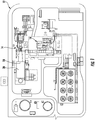
Figure 1 is a schematic diagram of the duct fired, combined cycle power generation plant. -
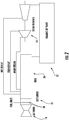
Figure 2 is a schematic diagram of the system for increasing the responsiveness of the duct fired, combined cycle power generation plant. -
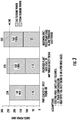
Figure 3 is a graph of base load redistribution of the duct fired, combined cycle power generation plant. -
Figure 4 is a graph of proposed ramp up of the duct fired, combined cycle power generation plant. -
Figure 5 is a graph of proposed ramp down of the duct fired, combined cycle power generation plant. - As shown in
Figures 1-5 , asystem 10 and method for increasing the responsiveness of a duct fired, combined cyclepower generation plant 12 via operating one or moregas turbine engines 14 at a part load condition less than 100 percent load, one or moresteam turbine engines 16, and one or moresupplemental burners 18 providing additional heat to a heatrecovery steam generator 20 upstream from thesteam turbine engine 16 is disclosed. The combination of thesteam turbine engines 16 andsupplemental burners 18 operating together withgas turbine engines 14 at a part load condition enables thesystem 10 to quickly change output to accommodate changes in output demand of the duct fired, combined cyclepower generation plant 12. By operating the one or moregas turbine engines 14 at a part load condition, thegas turbine engines 14 are able to be used to increase net output of the combined cyclepower generation plant 12 faster than relying on increasing output via duct firing. - In at least one embodiment, the
system 10 may include a method for increasing the responsiveness of a duct fired, combined cyclepower generation plant 12 such that thegas turbine engines 14 are only operating at part load, thereby providing the ability for the output of thegas turbine engines 14 to be increased or decreased to change the output of the combined cyclepower generation plant 12. As such, because the output of agas turbine engine 14 may be changed more rapidly than the output of asteam turbine engines 16, the output of the combined cyclepower generation plant 12 may be changed more rapidly when the output of agas turbine engine 14 is changed. In at least one embodiment, thesystem 10 may include operating one or moregas turbine engines 14 at a part load condition less than 100 percent load and operating one or moresteam turbine engines 16. In at least one embodiment, thesteam turbine engine 16 may be operated via steam created at least in part from heat generated by thegas turbine engine 16. The method may include firing one or moresupplemental burners 18, as shown inFigure 2 , to provide additional heat to a heatrecovery steam generator 20 upstream from thesteam turbine engine 16 such that combined output of thegas turbine engine 14 at part load and thesteam turbine engine 16 with additional steam input generated by firing thesupplemental burner 18 upstream of the heatrecovery steam generator 20 upstream is at least as great as operating thegas turbine engine 14 at 100 percent load condition and thesteam turbine engine 14 at 100 percent load condition. The method may also include controlling thegas turbine engine 14 to change output of thegas turbine engine 14 to accommodate changes in output demand placed on the duct fired, combined cyclepower generation plant 12 by controllers of the power grid to which the combined cyclepower generation plant 12 is connected or by other controlling decision makers and the like. - The
gas turbine engines 14 used within thesystem 10 may have any appropriate configuration enabling thegas turbine engines 14 to operate on a fuel source and create rotary motion of a shaft coupled to a generator to create power. In at least one embodiment, thegas turbine engine 14 may be controlled such that the controlling thegas turbine engine 14 to change output of thegas turbine engine 14 to accommodate changes in output demand includes increasing output of thegas turbine engine 14 to increase output of the duct fired, combined cyclepower generation plant 12 to accommodate an increase in output demand. In at least one embodiment, thegas turbine engine 14 may accommodate changes in output demand by increasing output of the duct fired, combined cyclepower generation plant 12 at a rate of at least five megawatts per minute. In another embodiment, thegas turbine engine 14 may accommodate changes in output demand by increasing output of the duct fired, combined cyclepower generation plant 12 at a rate of at least ten megawatts per minute. In yet another embodiment, thegas turbine engine 14 may accommodate changes in output demand by increasing output by increasing output of the duct fired, combined cyclepower generation plant 12 at a rate of at least fifteen megawatts per minute. - For example, as shown in
Figure 1 , the duct fired, combined cyclepower generation plant 12 may be a 1x1 plant running agas turbine engine 14 at part load less than 100 percent with at least onesupplemental burner 18 operating together with at least onesteam turbine engine 16 such that the total plant load is equal to the plant load with thegas turbine engine 14 and the at least onesteam turbine engine 16 running at 100 percent with the at least onesupplemental burner 18 turned off. In this case, thepower generation plant 12 is formed from one gas turbine and one steam turbine. In other embodiments, a 2x1 plant has two gas turbines and one steam turbine. Using a heatrecovery steam generator 20, one or moregas turbine engines 14 may be brought to a part load condition as thesupplemental burners 18 may be turned on with thesteam turbine engines 16 before base load operation of thegas turbine engines 14. As shown inFigure 3 , the output of the duct fired, combined cyclepower generation plant 12 may be the same load level as theplant 12 achieves withgas turbine engines 14 at 100 percent load without use ofsupplemental burners 18. For example, if thegas turbine engine 14 is at 90 percent load and is an F class, which refers to the firing temperatures and efficiency of the gas turbine engine, without fast starting capability, the duct fired, combined cyclepower generation plant 12 may be operated with about 15 megawatts of flexibility for very rapid load changes on a 1x1 plant at a rate of about 10 megawatts per minute. A ramp up process in which thegas turbine engine 14 is ramped up may be followed by an increase in output of thesupplemental burner 18. As such, the approximately 15 megawatts of incremental gas turbine engine output may be augmented by incremental power from thesteam turbine engines 16 resulting from the increase in exhaust energy from thegas turbine engines 14 at a rate of about 3-4 megawatts per minute, which provides theplant 12 with an effective plant ramp capability of about 15-20 megawatts per minute. - In another embodiment, as shown in
Figure 4 , the duct fired, combined cyclepower generation plant 12 may be operated with one or moregas turbine engines 14 at less than 90 percent, such as at 80 percent load, rather than an equivalent gross power output of thegas turbine engines 14 operating at 100 percent load with thesupplemental burners 18 turned off. As such, thegas turbine engine 14 may have about 30 megawatts of flexible available output that may be added to the output of theplant 12 by increasing the output of thegas turbine engines 14. Based upon the rates discussed above, the 30 megawatts of additional output could be added to the output of theplant 12 in about two to three minutes. - The method of using the
system 10 may include a ramp down process in which output of thegas turbine engine 14 is ramped down. The ramp down process in which the output of thegas turbine engine 14 is ramped down may be followed by a decrease in output of thesupplemental burner 18. As shown inFigure 5 , the method of using thesystem 10 whereby a ramp down of thegas turbine engine 14 is accomplished at a ramp rate that is faster than conventional systems in which the ramp down is initially only controlled by discontinuing use of duct burners. More specifically,Figure 5 depicts a ramp down procedure wherein thegas turbine engine 14 ramps down at a rate of about 10-15 megawatts per minute, with a total ramp down of power output of about 70 megawatts in about four to five minutes. - In embodiments where the one or more
gas turbine engines 14 have a fast start capability, thegas turbine engines 14 may ramp up or down at a rate of about 30 megawatts per minute. Thus, the process of ramping up or down the duct fired, combined cyclepower generation plant 12 may be reduced to about one minute in time using thegas turbine engine 14 only, rather than thesupplemental burner 18 and thesteam turbine engine 16. The ramp rate of thegas turbine engine 14 drives the ramp of the entire duct fired, combined cyclepower generation plant 12. Thesteam turbine engine 16 follows the ramp rate of thegas turbine engine 14 directionally but at a rate driven by the time constant of the heatrecovery steam generator 20 and balance of systems of theplant 12. The rate of change of thesteam turbine engine 16 will also be bounded by the steam turbine transient requirements of a particular turbine product. - According to the invention, the
system 10 is also configured such that wherein firing at least onesupplemental burner 18 to provide additional heat to a heatrecovery steam generator 20, thesupplemental burner 18 is fired during a startup process in which thegas turbine engine 14 starts operating to enable the heatrecovery steam generator 20 to warm up faster and allow excess steam to be provided to gland seals and a condenser. By allowing excess steam to be provided to gland seals and the condenser, less demand would be made of the auxiliary boiler such that the auxiliary boiler could be used less or eliminated. Thesystem 10 may also be configured such that the heating surface of the heatrecovery steam generator 20 could be arranged to optimize the entire heatrecovery steam generator 20 design to maximize steam production from the heating surfaces downstream of thesupplemental burner 18. For example, in a 1x1 cycle design, an intermediate pressure superheater may be positioned downstream of thesupplemental burner 18. In a 1x1 cycle design, a high pressure superheater may be positioned downstream of thesupplemental burner 18. - The foregoing is provided for purposes of illustrating, explaining, and describing embodiments of this invention. Modifications and adaptations to these embodiments will be apparent to those skilled in the art and may be made without departing from the scope of this invention.
Claims (9)
- A method for increasing the responsiveness of a duct fired, combined cycle power generation plant (12), comprising:operating at least one gas turbine engine (14) at a part load condition less than 100 percent load;operating at least one steam turbine engine (16) via steam created at least in part from heat generated by the at least one gas turbine engine (14);firing at least one supplemental burner (18) to provide additional heat to a heat recovery steam generator (20) upstream from the at least one steam turbine engine (16) such that combined output of the at least one gas turbine engine (14) at part load and the at least one steam turbine engine (16) with additional steam input generated by firing the at least one supplemental burner (18) upstream of the heat recovery steam generator (20) upstream is at least as great as operating the at least one gas turbine engine (14) at 100 percent load condition and the at least one steam turbine engine (16) at 100 percent load condition; andcontrolling the at least one gas turbine engine (14) to change output of the at least one gas turbine engine (14) to accommodate changes in output demand of the duct fired, combined cycle power generation plant (12) characterized in that the step of firing at least one supplemental burner (18) to provide additional heat to a heat recovery steam generator (20) upstream comprises firing at least one supplemental burner (18) during a startup process in which the at least one gas turbine engine (14) starts operating to enable the heat recovery steam generator (20) to warm up faster and allow excess steam to be provided to gland seals and a condenser.
- The method of claim 1, wherein controlling the at least one gas turbine engine (14) to change output of the at least one gas turbine engine (14) to accommodate changes in output demand comprises increasing output of the at least one gas turbine engine (14) to increase output of the duct fired, combined cycle power generation plant (12) to accommodate an increase in output demand.
- The method of claim 2, wherein increasing output of the duct fired, combined cycle power generation plant (12) to accommodate an increase in output demand comprises increasing output of the duct fired, combined cycle power generation plant (12) at a rate of at least five megawatts per minute.
- The method of claim 2, wherein increasing output of the duct fired, combined cycle power generation plant (12) to accommodate an increase in output demand comprises increasing output of the duct fired, combined cycle power generation plant (12) at a rate of at least ten megawatts per minute.
- The method of claim 2, wherein increasing output of the duct fired, combined cycle power generation plant (12) to accommodate an increase in output demand comprises increasing output of the duct fired, combined cycle power generation plant (12) at a rate of at least fifteen megawatts per minute.
- The method of claim 1, wherein operating at least one gas turbine engine (14) at a part load condition less than 100 percent load comprises operating the at least one gas turbine engine (14) at a part load condition less than 90 percent load.
- The method of claim 1, further comprising a ramp up process in which the at least one gas turbine engine (14) is ramped up followed by an increase in output of the at least one supplemental burner (18).
- The method of claim 1, further comprising a ramp down process in which output of the at least one gas turbine engine (14) is ramped down.
- The method of claim 8, wherein the ramp down process in which the output of the at least one gas turbine engine (14) is ramped down is followed by a decrease in output of the at least one supplemental burner (18).
Applications Claiming Priority (1)
| Application Number | Priority Date | Filing Date | Title |
|---|---|---|---|
| PCT/US2014/062080 WO2016064411A1 (en) | 2014-10-24 | 2014-10-24 | System and method for increasing the responsiveness of a duct fired, combined cycle, power generation plant |
Publications (2)
| Publication Number | Publication Date |
|---|---|
| EP3209867A1 EP3209867A1 (en) | 2017-08-30 |
| EP3209867B1 true EP3209867B1 (en) | 2021-06-16 |
Family
ID=51847013
Family Applications (1)
| Application Number | Title | Priority Date | Filing Date |
|---|---|---|---|
| EP14793409.5A Active EP3209867B1 (en) | 2014-10-24 | 2014-10-24 | System and method for increasing the responsiveness of a duct fired, combined cycle, power generation plant |
Country Status (5)
| Country | Link |
|---|---|
| US (1) | US10100681B2 (en) |
| EP (1) | EP3209867B1 (en) |
| JP (1) | JP2017535713A (en) |
| CN (1) | CN107075976B (en) |
| WO (1) | WO2016064411A1 (en) |
Families Citing this family (1)
| Publication number | Priority date | Publication date | Assignee | Title |
|---|---|---|---|---|
| JP6768379B2 (en) | 2016-07-12 | 2020-10-14 | 三菱パワー株式会社 | How to start a combined cycle plant, its control device, and a steam turbine |
Family Cites Families (9)
| Publication number | Priority date | Publication date | Assignee | Title |
|---|---|---|---|---|
| US3505811A (en) * | 1968-09-23 | 1970-04-14 | Gen Electric | Control system for a combined gas turbine and steam turbine power plant |
| US3980100A (en) | 1974-10-23 | 1976-09-14 | General Electric Company | Fluid flow control system |
| DE10115131A1 (en) | 2001-03-27 | 2002-10-17 | Alstom Switzerland Ltd | Process for the immediate, quick and temporary increase in the output of a combined cycle power plant |
| WO2002081870A1 (en) * | 2001-04-06 | 2002-10-17 | Alstom (Switzerland) Ltd | Method for placing a combined power plant on standby |
| US8359868B2 (en) * | 2008-09-11 | 2013-01-29 | General Electric Company | Low BTU fuel flow ratio duct burner for heating and heat recovery systems |
| US8387356B2 (en) | 2009-11-02 | 2013-03-05 | General Electric Company | Method of increasing power output of a combined cycle power plant during select operating periods |
| DK2630342T3 (en) * | 2010-10-19 | 2014-12-15 | Alstom Technology Ltd | Method for operation of a gas / steam-combi power plant with cogeneration and a gas / steam-combi power plant for carrying out the process |
| JP5552025B2 (en) | 2010-10-29 | 2014-07-16 | 住友ゴム工業株式会社 | Rubber composition for tire and pneumatic tire |
| JP5774381B2 (en) | 2011-05-31 | 2015-09-09 | 株式会社東芝 | Waste heat recovery boiler and power plant |
-
2014
- 2014-10-24 WO PCT/US2014/062080 patent/WO2016064411A1/en not_active Ceased
- 2014-10-24 CN CN201480082861.7A patent/CN107075976B/en not_active Expired - Fee Related
- 2014-10-24 EP EP14793409.5A patent/EP3209867B1/en active Active
- 2014-10-24 US US15/516,255 patent/US10100681B2/en active Active
- 2014-10-24 JP JP2017522378A patent/JP2017535713A/en active Pending
Non-Patent Citations (1)
| Title |
|---|
| None * |
Also Published As
| Publication number | Publication date |
|---|---|
| EP3209867A1 (en) | 2017-08-30 |
| JP2017535713A (en) | 2017-11-30 |
| US20170298782A1 (en) | 2017-10-19 |
| CN107075976A (en) | 2017-08-18 |
| CN107075976B (en) | 2020-03-31 |
| US10100681B2 (en) | 2018-10-16 |
| WO2016064411A1 (en) | 2016-04-28 |
Similar Documents
| Publication | Publication Date | Title |
|---|---|---|
| CN104251143B (en) | Start control unit for steam turbine plant | |
| US20110210555A1 (en) | Gas turbine driven electric power system with constant output through a full range of ambient conditions | |
| CN102200103B (en) | Integrated solar combined-cycle power generation plant and How It Works thereof | |
| GB2449181A (en) | Solar hybrid combined cycle power plant | |
| CA2755603A1 (en) | System for the generation of mechanical and/or electrical energy | |
| WO2013038423A3 (en) | Combined cooling/heating and power generation system utilizing sustainable energy | |
| US20100281870A1 (en) | System and method for heating fuel for a gas turbine | |
| EP3306043A1 (en) | Combined cycle plant, device for controlling said plant and method for starting up said plant | |
| De Paepe et al. | Experimental characterization of a T100 micro gas turbine converted to full humid air operation | |
| US9500103B2 (en) | Duct fired combined cycle system | |
| Mehrpanahi et al. | Multi-objective linear regression based optimization of full repowering a single pressure steam power plant | |
| EP2770172B1 (en) | Method for providing a frequency response for a combined cycle power plant | |
| US9127574B2 (en) | Method for operating a power plant | |
| US10100681B2 (en) | System and method for increasing the responsiveness of a duct fired, combined cycle, power generation plant | |
| Traverso et al. | Dynamic analysis of concentrated solar hybridised gas turbine | |
| JP2015031453A (en) | Transformation operation method of boiler plant for thermal power generation | |
| RU2528214C2 (en) | Gas turbine co-generation power plant | |
| Nassar et al. | New dynamic model for gas power plants for increasing wind and solar energy in the Egyptian power system | |
| US20170248036A1 (en) | System and method for managing heat recovery steam generator inlet temperature | |
| Rossi et al. | Ambient temperature impact on micro gas turbines: Experimental characterization | |
| US9840939B2 (en) | Variable fuel gas moisture control for gas turbine combustor | |
| JP2014125987A (en) | Gas turbine system and method of operating the gas turbine system | |
| JP2017187039A (en) | Power generation system | |
| Tugarinova | Arrangement and functional concept of a gas-fired power plant | |
| Olegovich et al. | GAS TURBINE AND COMBINED CYCLE PLANT |
Legal Events
| Date | Code | Title | Description |
|---|---|---|---|
| STAA | Information on the status of an ep patent application or granted ep patent |
Free format text: STATUS: THE INTERNATIONAL PUBLICATION HAS BEEN MADE |
|
| PUAI | Public reference made under article 153(3) epc to a published international application that has entered the european phase |
Free format text: ORIGINAL CODE: 0009012 |
|
| STAA | Information on the status of an ep patent application or granted ep patent |
Free format text: STATUS: REQUEST FOR EXAMINATION WAS MADE |
|
| 17P | Request for examination filed |
Effective date: 20170308 |
|
| AK | Designated contracting states |
Kind code of ref document: A1 Designated state(s): AL AT BE BG CH CY CZ DE DK EE ES FI FR GB GR HR HU IE IS IT LI LT LU LV MC MK MT NL NO PL PT RO RS SE SI SK SM TR |
|
| AX | Request for extension of the european patent |
Extension state: BA ME |
|
| DAX | Request for extension of the european patent (deleted) | ||
| STAA | Information on the status of an ep patent application or granted ep patent |
Free format text: STATUS: EXAMINATION IS IN PROGRESS |
|
| 17Q | First examination report despatched |
Effective date: 20200504 |
|
| RAP1 | Party data changed (applicant data changed or rights of an application transferred) |
Owner name: SIEMENS ENERGY GLOBAL GMBH & CO. KG |
|
| GRAP | Despatch of communication of intention to grant a patent |
Free format text: ORIGINAL CODE: EPIDOSNIGR1 |
|
| STAA | Information on the status of an ep patent application or granted ep patent |
Free format text: STATUS: GRANT OF PATENT IS INTENDED |
|
| INTG | Intention to grant announced |
Effective date: 20210222 |
|
| GRAS | Grant fee paid |
Free format text: ORIGINAL CODE: EPIDOSNIGR3 |
|
| GRAA | (expected) grant |
Free format text: ORIGINAL CODE: 0009210 |
|
| STAA | Information on the status of an ep patent application or granted ep patent |
Free format text: STATUS: THE PATENT HAS BEEN GRANTED |
|
| AK | Designated contracting states |
Kind code of ref document: B1 Designated state(s): AL AT BE BG CH CY CZ DE DK EE ES FI FR GB GR HR HU IE IS IT LI LT LU LV MC MK MT NL NO PL PT RO RS SE SI SK SM TR |
|
| REG | Reference to a national code |
Ref country code: GB Ref legal event code: FG4D |
|
| REG | Reference to a national code |
Ref country code: CH Ref legal event code: EP |
|
| REG | Reference to a national code |
Ref country code: DE Ref legal event code: R096 Ref document number: 602014078165 Country of ref document: DE |
|
| REG | Reference to a national code |
Ref country code: AT Ref legal event code: REF Ref document number: 1402494 Country of ref document: AT Kind code of ref document: T Effective date: 20210715 |
|
| REG | Reference to a national code |
Ref country code: IE Ref legal event code: FG4D |
|
| REG | Reference to a national code |
Ref country code: NL Ref legal event code: FP |
|
| REG | Reference to a national code |
Ref country code: LT Ref legal event code: MG9D |
|
| PG25 | Lapsed in a contracting state [announced via postgrant information from national office to epo] |
Ref country code: LT Free format text: LAPSE BECAUSE OF FAILURE TO SUBMIT A TRANSLATION OF THE DESCRIPTION OR TO PAY THE FEE WITHIN THE PRESCRIBED TIME-LIMIT Effective date: 20210616 Ref country code: FI Free format text: LAPSE BECAUSE OF FAILURE TO SUBMIT A TRANSLATION OF THE DESCRIPTION OR TO PAY THE FEE WITHIN THE PRESCRIBED TIME-LIMIT Effective date: 20210616 Ref country code: BG Free format text: LAPSE BECAUSE OF FAILURE TO SUBMIT A TRANSLATION OF THE DESCRIPTION OR TO PAY THE FEE WITHIN THE PRESCRIBED TIME-LIMIT Effective date: 20210916 Ref country code: HR Free format text: LAPSE BECAUSE OF FAILURE TO SUBMIT A TRANSLATION OF THE DESCRIPTION OR TO PAY THE FEE WITHIN THE PRESCRIBED TIME-LIMIT Effective date: 20210616 |
|
| REG | Reference to a national code |
Ref country code: AT Ref legal event code: MK05 Ref document number: 1402494 Country of ref document: AT Kind code of ref document: T Effective date: 20210616 |
|
| PG25 | Lapsed in a contracting state [announced via postgrant information from national office to epo] |
Ref country code: LV Free format text: LAPSE BECAUSE OF FAILURE TO SUBMIT A TRANSLATION OF THE DESCRIPTION OR TO PAY THE FEE WITHIN THE PRESCRIBED TIME-LIMIT Effective date: 20210616 Ref country code: GR Free format text: LAPSE BECAUSE OF FAILURE TO SUBMIT A TRANSLATION OF THE DESCRIPTION OR TO PAY THE FEE WITHIN THE PRESCRIBED TIME-LIMIT Effective date: 20210917 Ref country code: NO Free format text: LAPSE BECAUSE OF FAILURE TO SUBMIT A TRANSLATION OF THE DESCRIPTION OR TO PAY THE FEE WITHIN THE PRESCRIBED TIME-LIMIT Effective date: 20210916 Ref country code: RS Free format text: LAPSE BECAUSE OF FAILURE TO SUBMIT A TRANSLATION OF THE DESCRIPTION OR TO PAY THE FEE WITHIN THE PRESCRIBED TIME-LIMIT Effective date: 20210616 Ref country code: SE Free format text: LAPSE BECAUSE OF FAILURE TO SUBMIT A TRANSLATION OF THE DESCRIPTION OR TO PAY THE FEE WITHIN THE PRESCRIBED TIME-LIMIT Effective date: 20210616 |
|
| PG25 | Lapsed in a contracting state [announced via postgrant information from national office to epo] |
Ref country code: SK Free format text: LAPSE BECAUSE OF FAILURE TO SUBMIT A TRANSLATION OF THE DESCRIPTION OR TO PAY THE FEE WITHIN THE PRESCRIBED TIME-LIMIT Effective date: 20210616 Ref country code: SM Free format text: LAPSE BECAUSE OF FAILURE TO SUBMIT A TRANSLATION OF THE DESCRIPTION OR TO PAY THE FEE WITHIN THE PRESCRIBED TIME-LIMIT Effective date: 20210616 Ref country code: CZ Free format text: LAPSE BECAUSE OF FAILURE TO SUBMIT A TRANSLATION OF THE DESCRIPTION OR TO PAY THE FEE WITHIN THE PRESCRIBED TIME-LIMIT Effective date: 20210616 Ref country code: EE Free format text: LAPSE BECAUSE OF FAILURE TO SUBMIT A TRANSLATION OF THE DESCRIPTION OR TO PAY THE FEE WITHIN THE PRESCRIBED TIME-LIMIT Effective date: 20210616 Ref country code: AT Free format text: LAPSE BECAUSE OF FAILURE TO SUBMIT A TRANSLATION OF THE DESCRIPTION OR TO PAY THE FEE WITHIN THE PRESCRIBED TIME-LIMIT Effective date: 20210616 Ref country code: ES Free format text: LAPSE BECAUSE OF FAILURE TO SUBMIT A TRANSLATION OF THE DESCRIPTION OR TO PAY THE FEE WITHIN THE PRESCRIBED TIME-LIMIT Effective date: 20210616 Ref country code: PT Free format text: LAPSE BECAUSE OF FAILURE TO SUBMIT A TRANSLATION OF THE DESCRIPTION OR TO PAY THE FEE WITHIN THE PRESCRIBED TIME-LIMIT Effective date: 20211018 Ref country code: RO Free format text: LAPSE BECAUSE OF FAILURE TO SUBMIT A TRANSLATION OF THE DESCRIPTION OR TO PAY THE FEE WITHIN THE PRESCRIBED TIME-LIMIT Effective date: 20210616 |
|
| PG25 | Lapsed in a contracting state [announced via postgrant information from national office to epo] |
Ref country code: PL Free format text: LAPSE BECAUSE OF FAILURE TO SUBMIT A TRANSLATION OF THE DESCRIPTION OR TO PAY THE FEE WITHIN THE PRESCRIBED TIME-LIMIT Effective date: 20210616 |
|
| REG | Reference to a national code |
Ref country code: DE Ref legal event code: R097 Ref document number: 602014078165 Country of ref document: DE |
|
| PLBE | No opposition filed within time limit |
Free format text: ORIGINAL CODE: 0009261 |
|
| STAA | Information on the status of an ep patent application or granted ep patent |
Free format text: STATUS: NO OPPOSITION FILED WITHIN TIME LIMIT |
|
| PG25 | Lapsed in a contracting state [announced via postgrant information from national office to epo] |
Ref country code: DK Free format text: LAPSE BECAUSE OF FAILURE TO SUBMIT A TRANSLATION OF THE DESCRIPTION OR TO PAY THE FEE WITHIN THE PRESCRIBED TIME-LIMIT Effective date: 20210616 |
|
| 26N | No opposition filed |
Effective date: 20220317 |
|
| PG25 | Lapsed in a contracting state [announced via postgrant information from national office to epo] |
Ref country code: AL Free format text: LAPSE BECAUSE OF FAILURE TO SUBMIT A TRANSLATION OF THE DESCRIPTION OR TO PAY THE FEE WITHIN THE PRESCRIBED TIME-LIMIT Effective date: 20210616 |
|
| REG | Reference to a national code |
Ref country code: CH Ref legal event code: PL |
|
| REG | Reference to a national code |
Ref country code: BE Ref legal event code: MM Effective date: 20211031 |
|
| GBPC | Gb: european patent ceased through non-payment of renewal fee |
Effective date: 20211024 |
|
| PG25 | Lapsed in a contracting state [announced via postgrant information from national office to epo] |
Ref country code: MC Free format text: LAPSE BECAUSE OF FAILURE TO SUBMIT A TRANSLATION OF THE DESCRIPTION OR TO PAY THE FEE WITHIN THE PRESCRIBED TIME-LIMIT Effective date: 20210616 |
|
| PG25 | Lapsed in a contracting state [announced via postgrant information from national office to epo] |
Ref country code: LU Free format text: LAPSE BECAUSE OF NON-PAYMENT OF DUE FEES Effective date: 20211024 Ref country code: GB Free format text: LAPSE BECAUSE OF NON-PAYMENT OF DUE FEES Effective date: 20211024 Ref country code: BE Free format text: LAPSE BECAUSE OF NON-PAYMENT OF DUE FEES Effective date: 20211031 |
|
| PG25 | Lapsed in a contracting state [announced via postgrant information from national office to epo] |
Ref country code: LI Free format text: LAPSE BECAUSE OF NON-PAYMENT OF DUE FEES Effective date: 20211031 Ref country code: CH Free format text: LAPSE BECAUSE OF NON-PAYMENT OF DUE FEES Effective date: 20211031 |
|
| PG25 | Lapsed in a contracting state [announced via postgrant information from national office to epo] |
Ref country code: FR Free format text: LAPSE BECAUSE OF NON-PAYMENT OF DUE FEES Effective date: 20211031 |
|
| PG25 | Lapsed in a contracting state [announced via postgrant information from national office to epo] |
Ref country code: IE Free format text: LAPSE BECAUSE OF NON-PAYMENT OF DUE FEES Effective date: 20211024 |
|
| PG25 | Lapsed in a contracting state [announced via postgrant information from national office to epo] |
Ref country code: HU Free format text: LAPSE BECAUSE OF FAILURE TO SUBMIT A TRANSLATION OF THE DESCRIPTION OR TO PAY THE FEE WITHIN THE PRESCRIBED TIME-LIMIT; INVALID AB INITIO Effective date: 20141024 |
|
| PG25 | Lapsed in a contracting state [announced via postgrant information from national office to epo] |
Ref country code: CY Free format text: LAPSE BECAUSE OF FAILURE TO SUBMIT A TRANSLATION OF THE DESCRIPTION OR TO PAY THE FEE WITHIN THE PRESCRIBED TIME-LIMIT Effective date: 20210616 |
|
| PG25 | Lapsed in a contracting state [announced via postgrant information from national office to epo] |
Ref country code: MK Free format text: LAPSE BECAUSE OF FAILURE TO SUBMIT A TRANSLATION OF THE DESCRIPTION OR TO PAY THE FEE WITHIN THE PRESCRIBED TIME-LIMIT Effective date: 20210616 |
|
| PG25 | Lapsed in a contracting state [announced via postgrant information from national office to epo] |
Ref country code: MT Free format text: LAPSE BECAUSE OF FAILURE TO SUBMIT A TRANSLATION OF THE DESCRIPTION OR TO PAY THE FEE WITHIN THE PRESCRIBED TIME-LIMIT Effective date: 20210616 |
|
| PGFP | Annual fee paid to national office [announced via postgrant information from national office to epo] |
Ref country code: NL Payment date: 20251024 Year of fee payment: 12 |
|
| PG25 | Lapsed in a contracting state [announced via postgrant information from national office to epo] |
Ref country code: TR Free format text: LAPSE BECAUSE OF FAILURE TO SUBMIT A TRANSLATION OF THE DESCRIPTION OR TO PAY THE FEE WITHIN THE PRESCRIBED TIME-LIMIT Effective date: 20210616 |
|
| PGFP | Annual fee paid to national office [announced via postgrant information from national office to epo] |
Ref country code: DE Payment date: 20251028 Year of fee payment: 12 |
|
| PGFP | Annual fee paid to national office [announced via postgrant information from national office to epo] |
Ref country code: IT Payment date: 20251022 Year of fee payment: 12 |