EP3209377B1 - Delivery devices for leadless cardiac devices - Google Patents
Delivery devices for leadless cardiac devices Download PDFInfo
- Publication number
- EP3209377B1 EP3209377B1 EP15790392.3A EP15790392A EP3209377B1 EP 3209377 B1 EP3209377 B1 EP 3209377B1 EP 15790392 A EP15790392 A EP 15790392A EP 3209377 B1 EP3209377 B1 EP 3209377B1
- Authority
- EP
- European Patent Office
- Prior art keywords
- tubular member
- hub portion
- delivery device
- outer tubular
- inner tubular
- Prior art date
- Legal status (The legal status is an assumption and is not a legal conclusion. Google has not performed a legal analysis and makes no representation as to the accuracy of the status listed.)
- Active
Links
- 230000000747 cardiac effect Effects 0.000 title description 8
- 230000007246 mechanism Effects 0.000 claims description 95
- 230000006835 compression Effects 0.000 claims description 17
- 238000007906 compression Methods 0.000 claims description 17
- 239000000463 material Substances 0.000 description 28
- 229910001000 nickel titanium Inorganic materials 0.000 description 25
- HLXZNVUGXRDIFK-UHFFFAOYSA-N nickel titanium Chemical compound [Ti].[Ti].[Ti].[Ti].[Ti].[Ti].[Ti].[Ti].[Ti].[Ti].[Ti].[Ni].[Ni].[Ni].[Ni].[Ni].[Ni].[Ni].[Ni].[Ni].[Ni].[Ni].[Ni].[Ni].[Ni] HLXZNVUGXRDIFK-UHFFFAOYSA-N 0.000 description 16
- 238000000034 method Methods 0.000 description 12
- -1 polytetrafluoroethylene Polymers 0.000 description 11
- 210000003484 anatomy Anatomy 0.000 description 9
- 230000008878 coupling Effects 0.000 description 9
- 238000010168 coupling process Methods 0.000 description 9
- 238000005859 coupling reaction Methods 0.000 description 9
- 210000005003 heart tissue Anatomy 0.000 description 8
- 210000001519 tissue Anatomy 0.000 description 8
- 229910001182 Mo alloy Inorganic materials 0.000 description 7
- 229910045601 alloy Inorganic materials 0.000 description 7
- 239000000956 alloy Substances 0.000 description 7
- 239000007943 implant Substances 0.000 description 7
- 229910052751 metal Inorganic materials 0.000 description 7
- 239000002184 metal Substances 0.000 description 7
- 230000006870 function Effects 0.000 description 6
- 230000013011 mating Effects 0.000 description 6
- 210000005241 right ventricle Anatomy 0.000 description 6
- 238000005452 bending Methods 0.000 description 5
- 239000012530 fluid Substances 0.000 description 5
- 238000003032 molecular docking Methods 0.000 description 5
- 229920000642 polymer Polymers 0.000 description 5
- PXHVJJICTQNCMI-UHFFFAOYSA-N Nickel Chemical compound [Ni] PXHVJJICTQNCMI-UHFFFAOYSA-N 0.000 description 4
- 229910000856 hastalloy Inorganic materials 0.000 description 4
- 238000004519 manufacturing process Methods 0.000 description 4
- 229910001092 metal group alloy Inorganic materials 0.000 description 4
- 239000000203 mixture Substances 0.000 description 4
- BASFCYQUMIYNBI-UHFFFAOYSA-N platinum Chemical compound [Pt] BASFCYQUMIYNBI-UHFFFAOYSA-N 0.000 description 4
- 229920001343 polytetrafluoroethylene Polymers 0.000 description 4
- 239000004810 polytetrafluoroethylene Substances 0.000 description 4
- 239000010935 stainless steel Substances 0.000 description 4
- 229910001220 stainless steel Inorganic materials 0.000 description 4
- RTZKZFJDLAIYFH-UHFFFAOYSA-N Diethyl ether Chemical compound CCOCC RTZKZFJDLAIYFH-UHFFFAOYSA-N 0.000 description 3
- 229920000106 Liquid crystal polymer Polymers 0.000 description 3
- 239000004977 Liquid-crystal polymers (LCPs) Substances 0.000 description 3
- 239000004952 Polyamide Substances 0.000 description 3
- 229920002614 Polyether block amide Polymers 0.000 description 3
- 239000004721 Polyphenylene oxide Substances 0.000 description 3
- 239000002775 capsule Substances 0.000 description 3
- 238000002595 magnetic resonance imaging Methods 0.000 description 3
- 229920002647 polyamide Polymers 0.000 description 3
- 210000005245 right atrium Anatomy 0.000 description 3
- 230000000638 stimulation Effects 0.000 description 3
- 229910000881 Cu alloy Inorganic materials 0.000 description 2
- 239000004812 Fluorinated ethylene propylene Substances 0.000 description 2
- 229920000339 Marlex Polymers 0.000 description 2
- KDLHZDBZIXYQEI-UHFFFAOYSA-N Palladium Chemical compound [Pd] KDLHZDBZIXYQEI-UHFFFAOYSA-N 0.000 description 2
- 239000004696 Poly ether ether ketone Substances 0.000 description 2
- 239000004697 Polyetherimide Substances 0.000 description 2
- 239000004698 Polyethylene Substances 0.000 description 2
- 239000004642 Polyimide Substances 0.000 description 2
- 239000004734 Polyphenylene sulfide Substances 0.000 description 2
- 239000004743 Polypropylene Substances 0.000 description 2
- RTAQQCXQSZGOHL-UHFFFAOYSA-N Titanium Chemical compound [Ti] RTAQQCXQSZGOHL-UHFFFAOYSA-N 0.000 description 2
- 229910001080 W alloy Inorganic materials 0.000 description 2
- MTHLBYMFGWSRME-UHFFFAOYSA-N [Cr].[Co].[Mo] Chemical compound [Cr].[Co].[Mo] MTHLBYMFGWSRME-UHFFFAOYSA-N 0.000 description 2
- HZEWFHLRYVTOIW-UHFFFAOYSA-N [Ti].[Ni] Chemical compound [Ti].[Ni] HZEWFHLRYVTOIW-UHFFFAOYSA-N 0.000 description 2
- 238000004458 analytical method Methods 0.000 description 2
- 229910001566 austenite Inorganic materials 0.000 description 2
- 210000005242 cardiac chamber Anatomy 0.000 description 2
- 230000008859 change Effects 0.000 description 2
- 239000000788 chromium alloy Substances 0.000 description 2
- PRQRQKBNBXPISG-UHFFFAOYSA-N chromium cobalt molybdenum nickel Chemical compound [Cr].[Co].[Ni].[Mo] PRQRQKBNBXPISG-UHFFFAOYSA-N 0.000 description 2
- 238000004891 communication Methods 0.000 description 2
- 229920001577 copolymer Polymers 0.000 description 2
- YOCUPQPZWBBYIX-UHFFFAOYSA-N copper nickel Chemical compound [Ni].[Cu] YOCUPQPZWBBYIX-UHFFFAOYSA-N 0.000 description 2
- 238000013461 design Methods 0.000 description 2
- 238000000113 differential scanning calorimetry Methods 0.000 description 2
- 229910000701 elgiloys (Co-Cr-Ni Alloy) Inorganic materials 0.000 description 2
- 150000002148 esters Chemical class 0.000 description 2
- 229920000840 ethylene tetrafluoroethylene copolymer Polymers 0.000 description 2
- 210000003191 femoral vein Anatomy 0.000 description 2
- 229910000734 martensite Inorganic materials 0.000 description 2
- DDTIGTPWGISMKL-UHFFFAOYSA-N molybdenum nickel Chemical compound [Ni].[Mo] DDTIGTPWGISMKL-UHFFFAOYSA-N 0.000 description 2
- 229910052759 nickel Inorganic materials 0.000 description 2
- 229920009441 perflouroethylene propylene Polymers 0.000 description 2
- 230000004962 physiological condition Effects 0.000 description 2
- 229910052697 platinum Inorganic materials 0.000 description 2
- 238000009428 plumbing Methods 0.000 description 2
- 229920001200 poly(ethylene-vinyl acetate) Polymers 0.000 description 2
- 229920001707 polybutylene terephthalate Polymers 0.000 description 2
- 229920000728 polyester Polymers 0.000 description 2
- 229920002530 polyetherether ketone Polymers 0.000 description 2
- 229920001601 polyetherimide Polymers 0.000 description 2
- 229920000573 polyethylene Polymers 0.000 description 2
- 229920000139 polyethylene terephthalate Polymers 0.000 description 2
- 239000005020 polyethylene terephthalate Substances 0.000 description 2
- 229920001721 polyimide Polymers 0.000 description 2
- 229920006324 polyoxymethylene Polymers 0.000 description 2
- 229920006380 polyphenylene oxide Polymers 0.000 description 2
- 229920000069 polyphenylene sulfide Polymers 0.000 description 2
- 229920001155 polypropylene Polymers 0.000 description 2
- 229920002635 polyurethane Polymers 0.000 description 2
- 239000004814 polyurethane Substances 0.000 description 2
- 239000010936 titanium Substances 0.000 description 2
- 229910052719 titanium Inorganic materials 0.000 description 2
- 210000000591 tricuspid valve Anatomy 0.000 description 2
- 210000005166 vasculature Anatomy 0.000 description 2
- 210000001631 vena cava inferior Anatomy 0.000 description 2
- 230000000007 visual effect Effects 0.000 description 2
- KHXKESCWFMPTFT-UHFFFAOYSA-N 1,1,1,2,2,3,3-heptafluoro-3-(1,2,2-trifluoroethenoxy)propane Chemical compound FC(F)=C(F)OC(F)(F)C(F)(F)C(F)(F)F KHXKESCWFMPTFT-UHFFFAOYSA-N 0.000 description 1
- 229910000531 Co alloy Inorganic materials 0.000 description 1
- 229920004943 Delrin® Polymers 0.000 description 1
- 229920006055 Durethan® Polymers 0.000 description 1
- 239000004593 Epoxy Substances 0.000 description 1
- 229920000219 Ethylene vinyl alcohol Polymers 0.000 description 1
- 229910000640 Fe alloy Inorganic materials 0.000 description 1
- 229920003620 Grilon® Polymers 0.000 description 1
- 229920000271 Kevlar® Polymers 0.000 description 1
- JHWNWJKBPDFINM-UHFFFAOYSA-N Laurolactam Chemical compound O=C1CCCCCCCCCCCN1 JHWNWJKBPDFINM-UHFFFAOYSA-N 0.000 description 1
- 229910001209 Low-carbon steel Inorganic materials 0.000 description 1
- 229910000792 Monel Inorganic materials 0.000 description 1
- 229910000990 Ni alloy Inorganic materials 0.000 description 1
- 239000004677 Nylon Substances 0.000 description 1
- 229920000299 Nylon 12 Polymers 0.000 description 1
- 229930040373 Paraformaldehyde Natural products 0.000 description 1
- 229920000265 Polyparaphenylene Polymers 0.000 description 1
- 239000004793 Polystyrene Substances 0.000 description 1
- QXZUUHYBWMWJHK-UHFFFAOYSA-N [Co].[Ni] Chemical compound [Co].[Ni] QXZUUHYBWMWJHK-UHFFFAOYSA-N 0.000 description 1
- 229920000249 biocompatible polymer Polymers 0.000 description 1
- 239000008280 blood Substances 0.000 description 1
- 210000004369 blood Anatomy 0.000 description 1
- 210000004204 blood vessel Anatomy 0.000 description 1
- 230000036760 body temperature Effects 0.000 description 1
- 239000000919 ceramic Substances 0.000 description 1
- OGSYQYXYGXIQFH-UHFFFAOYSA-N chromium molybdenum nickel Chemical compound [Cr].[Ni].[Mo] OGSYQYXYGXIQFH-UHFFFAOYSA-N 0.000 description 1
- 239000011248 coating agent Substances 0.000 description 1
- 238000000576 coating method Methods 0.000 description 1
- 239000002131 composite material Substances 0.000 description 1
- 239000004020 conductor Substances 0.000 description 1
- 230000000694 effects Effects 0.000 description 1
- 239000013013 elastic material Substances 0.000 description 1
- 229920001971 elastomer Polymers 0.000 description 1
- 239000000806 elastomer Substances 0.000 description 1
- 238000001827 electrotherapy Methods 0.000 description 1
- 229920006351 engineering plastic Polymers 0.000 description 1
- JBKVHLHDHHXQEQ-UHFFFAOYSA-N epsilon-caprolactam Chemical compound O=C1CCCCCN1 JBKVHLHDHHXQEQ-UHFFFAOYSA-N 0.000 description 1
- QHSJIZLJUFMIFP-UHFFFAOYSA-N ethene;1,1,2,2-tetrafluoroethene Chemical group C=C.FC(F)=C(F)F QHSJIZLJUFMIFP-UHFFFAOYSA-N 0.000 description 1
- HQQADJVZYDDRJT-UHFFFAOYSA-N ethene;prop-1-ene Chemical group C=C.CC=C HQQADJVZYDDRJT-UHFFFAOYSA-N 0.000 description 1
- 150000002170 ethers Chemical class 0.000 description 1
- 239000005038 ethylene vinyl acetate Substances 0.000 description 1
- 239000004715 ethylene vinyl alcohol Substances 0.000 description 1
- 238000000605 extraction Methods 0.000 description 1
- 239000003302 ferromagnetic material Substances 0.000 description 1
- 239000000945 filler Substances 0.000 description 1
- 238000002594 fluoroscopy Methods 0.000 description 1
- 238000011010 flushing procedure Methods 0.000 description 1
- PCHJSUWPFVWCPO-UHFFFAOYSA-N gold Chemical compound [Au] PCHJSUWPFVWCPO-UHFFFAOYSA-N 0.000 description 1
- 229910052737 gold Inorganic materials 0.000 description 1
- 239000010931 gold Substances 0.000 description 1
- RZXDTJIXPSCHCI-UHFFFAOYSA-N hexa-1,5-diene-2,5-diol Chemical compound OC(=C)CCC(O)=C RZXDTJIXPSCHCI-UHFFFAOYSA-N 0.000 description 1
- 229920001903 high density polyethylene Polymers 0.000 description 1
- 239000004700 high-density polyethylene Substances 0.000 description 1
- 238000003384 imaging method Methods 0.000 description 1
- 238000002513 implantation Methods 0.000 description 1
- 229910001026 inconel Inorganic materials 0.000 description 1
- 208000014674 injury Diseases 0.000 description 1
- 238000003780 insertion Methods 0.000 description 1
- 230000037431 insertion Effects 0.000 description 1
- 238000009413 insulation Methods 0.000 description 1
- 229920000554 ionomer Polymers 0.000 description 1
- UGKDIUIOSMUOAW-UHFFFAOYSA-N iron nickel Chemical compound [Fe].[Ni] UGKDIUIOSMUOAW-UHFFFAOYSA-N 0.000 description 1
- 210000005246 left atrium Anatomy 0.000 description 1
- 210000005240 left ventricle Anatomy 0.000 description 1
- 229920000092 linear low density polyethylene Polymers 0.000 description 1
- 239000004707 linear low-density polyethylene Substances 0.000 description 1
- 229920001684 low density polyethylene Polymers 0.000 description 1
- 239000004702 low-density polyethylene Substances 0.000 description 1
- 239000003550 marker Substances 0.000 description 1
- 239000002905 metal composite material Substances 0.000 description 1
- 150000002739 metals Chemical class 0.000 description 1
- 230000005012 migration Effects 0.000 description 1
- 238000013508 migration Methods 0.000 description 1
- MOWMLACGTDMJRV-UHFFFAOYSA-N nickel tungsten Chemical compound [Ni].[W] MOWMLACGTDMJRV-UHFFFAOYSA-N 0.000 description 1
- 229910000623 nickel–chromium alloy Inorganic materials 0.000 description 1
- 229920001778 nylon Polymers 0.000 description 1
- 229910052763 palladium Inorganic materials 0.000 description 1
- VPRUMANMDWQMNF-UHFFFAOYSA-N phenylethane boronic acid Chemical compound OB(O)CCC1=CC=CC=C1 VPRUMANMDWQMNF-UHFFFAOYSA-N 0.000 description 1
- XNGIFLGASWRNHJ-UHFFFAOYSA-L phthalate(2-) Chemical compound [O-]C(=O)C1=CC=CC=C1C([O-])=O XNGIFLGASWRNHJ-UHFFFAOYSA-L 0.000 description 1
- 229920003023 plastic Polymers 0.000 description 1
- 239000004033 plastic Substances 0.000 description 1
- 229920002492 poly(sulfone) Polymers 0.000 description 1
- 239000004417 polycarbonate Substances 0.000 description 1
- 229920000515 polycarbonate Polymers 0.000 description 1
- 229920000570 polyether Polymers 0.000 description 1
- 239000011112 polyethylene naphthalate Substances 0.000 description 1
- 239000002861 polymer material Substances 0.000 description 1
- 229920000098 polyolefin Polymers 0.000 description 1
- 229920001296 polysiloxane Polymers 0.000 description 1
- 229920002223 polystyrene Polymers 0.000 description 1
- 229920002215 polytrimethylene terephthalate Polymers 0.000 description 1
- 239000004800 polyvinyl chloride Substances 0.000 description 1
- 239000005033 polyvinylidene chloride Substances 0.000 description 1
- 239000012781 shape memory material Substances 0.000 description 1
- 229920000431 shape-memory polymer Polymers 0.000 description 1
- 229910052715 tantalum Inorganic materials 0.000 description 1
- GUVRBAGPIYLISA-UHFFFAOYSA-N tantalum atom Chemical compound [Ta] GUVRBAGPIYLISA-UHFFFAOYSA-N 0.000 description 1
- MHSKRLJMQQNJNC-UHFFFAOYSA-N terephthalamide Chemical compound NC(=O)C1=CC=C(C(N)=O)C=C1 MHSKRLJMQQNJNC-UHFFFAOYSA-N 0.000 description 1
- 125000000383 tetramethylene group Chemical group [H]C([H])([*:1])C([H])([H])C([H])([H])C([H])([H])[*:2] 0.000 description 1
- 238000002076 thermal analysis method Methods 0.000 description 1
- 230000008733 trauma Effects 0.000 description 1
- 230000000472 traumatic effect Effects 0.000 description 1
- WFKWXMTUELFFGS-UHFFFAOYSA-N tungsten Chemical compound [W] WFKWXMTUELFFGS-UHFFFAOYSA-N 0.000 description 1
- 229910052721 tungsten Inorganic materials 0.000 description 1
- 239000010937 tungsten Substances 0.000 description 1
- 230000002792 vascular Effects 0.000 description 1
Images


Classifications
-
- A—HUMAN NECESSITIES
- A61—MEDICAL OR VETERINARY SCIENCE; HYGIENE
- A61N—ELECTROTHERAPY; MAGNETOTHERAPY; RADIATION THERAPY; ULTRASOUND THERAPY
- A61N1/00—Electrotherapy; Circuits therefor
- A61N1/02—Details
- A61N1/04—Electrodes
- A61N1/05—Electrodes for implantation or insertion into the body, e.g. heart electrode
- A61N1/0587—Epicardial electrode systems; Endocardial electrodes piercing the pericardium
-
- A—HUMAN NECESSITIES
- A61—MEDICAL OR VETERINARY SCIENCE; HYGIENE
- A61N—ELECTROTHERAPY; MAGNETOTHERAPY; RADIATION THERAPY; ULTRASOUND THERAPY
- A61N1/00—Electrotherapy; Circuits therefor
- A61N1/18—Applying electric currents by contact electrodes
- A61N1/32—Applying electric currents by contact electrodes alternating or intermittent currents
- A61N1/36—Applying electric currents by contact electrodes alternating or intermittent currents for stimulation
- A61N1/372—Arrangements in connection with the implantation of stimulators
- A61N1/375—Constructional arrangements, e.g. casings
- A61N1/3756—Casings with electrodes thereon, e.g. leadless stimulators
-
- A—HUMAN NECESSITIES
- A61—MEDICAL OR VETERINARY SCIENCE; HYGIENE
- A61N—ELECTROTHERAPY; MAGNETOTHERAPY; RADIATION THERAPY; ULTRASOUND THERAPY
- A61N1/00—Electrotherapy; Circuits therefor
- A61N1/18—Applying electric currents by contact electrodes
- A61N1/32—Applying electric currents by contact electrodes alternating or intermittent currents
- A61N1/36—Applying electric currents by contact electrodes alternating or intermittent currents for stimulation
- A61N1/372—Arrangements in connection with the implantation of stimulators
- A61N1/37205—Microstimulators, e.g. implantable through a cannula
-
- A—HUMAN NECESSITIES
- A61—MEDICAL OR VETERINARY SCIENCE; HYGIENE
- A61N—ELECTROTHERAPY; MAGNETOTHERAPY; RADIATION THERAPY; ULTRASOUND THERAPY
- A61N1/00—Electrotherapy; Circuits therefor
- A61N1/02—Details
- A61N1/04—Electrodes
- A61N1/05—Electrodes for implantation or insertion into the body, e.g. heart electrode
- A61N1/056—Transvascular endocardial electrode systems
- A61N1/057—Anchoring means; Means for fixing the head inside the heart
- A61N2001/058—Fixing tools
Definitions
- the present disclosure pertains to medical devices, and methods for manufacturing and/or using medical devices. More particularly, the present disclosure pertains to leadless cardiac devices and methods, such as leadless pacing devices and methods, and delivery devices and methods for such leadless devices.
- a wide variety of medical devices have been developed for medical use, for example, cardiac use. Some of these devices include catheters, leads, pacemakers, and the like, and delivery devices and/or systems used for delivering such devices. These devices are manufactured by any one of a variety of different manufacturing methods and may be used according to any one of a variety of methods. Of the known medical devices, delivery systems, and methods, each has certain advantages and disadvantages. There is an ongoing need to provide alternative medical devices and delivery devices as well as alternative methods for manufacturing and using medical devices and delivery devices.
- Document US 2011/0251662 relates to a fixation device for retaining a leadless medical implant to tissue including an array of elongate tines having self-expanding distal portions.
- the fixation tines may be advanced between an implant body and an outer jacket to deploy the tines from a delivery configuration in which the tines are constrained by the outer jacket to an expanded configuration in which the distal end portions of the tines are released from the outer jacket.
- the implant and fixation device are contained within a sheath for delivery to the treatment site and a pusher within the sheath advances the fixation device relative to the implant body and deploys the tines.
- a distal end of the implant having an electrode may form a distal tip of the delivery system, and a potential implantation site may be tested prior to deployment of the fixation device to allow for easy repositioning of the implant.
- This disclosure provides design, material, manufacturing method, and use alternatives for medical devices, including delivery devices.
- a delivery device for delivering an implantable leadless pacing device may comprise an outer tubular member including a lumen extending from a proximal end to a distal end thereof, an inner tubular member including a lumen extending from a proximal end to a distal end thereof, the inner tubular member slidably disposed within the lumen of the outer tubular member, a distal holding section extending distally of a distal end of the inner tubular member, the distal holding section defining a cavity therein for receiving an implantable leadless pacing device, a handle assembly including at least a first hub portion affixed adjacent to the proximal end of the outer tubular member and intermediate second hub portion affixed adjacent to the proximal end of the inner tubular member, and a first locking mechanism disposed within the handle assembly, wherein the first locking mechanism is configured to releasably couple the first hub portion and the second hub portion.
- the first locking mechanism may have a locked position and an unlocked position wherein the inner tubular member is held in tension in the locked position.
- the outer tubular member may be held in compression in the locked position.
- first hub portion and the second hub portion may be individually slidable and rotatable when the first locking mechanism is in an unlocked configuration.
- the first locking mechanism may be selected from the group of a snap lock, a threaded engagement, or a quick connect locking feature.
- the first locking mechanism may comprise a bayonet style locking mechanism.
- the second hub portion may comprise a groove positioned adjacent a distal end of the second hub portion , the groove configured to receive an inwardly extending protrusion of the first hub portion.
- the groove may comprise a first portion, a second portion extending generally orthogonal to the first portion, and a serif positioned at an end of the second portion.
- disposing the protrusion within the serif may releasably couple the outer tubular member and the inner tubular member such that longitudinal or rotational actuation of either of the outer tubular member or the inner tubular member results in corresponding actuation of both the outer tubular member and the inner tubular member.
- disposing the protrusion within the serif may place the inner tubular member in tension and the outer tubular member in compression.
- the device may further comprise a push member slidably disposed within the lumen of the inner tubular member.
- the device may further comprise a third hub portion affixed adjacent to a proximal end of the push member.
- the device may further comprise a second locking mechanism disposed within the handle assembly.
- the third hub portion may be slidable and rotatable independent of either of the first hub portion or the second hub portion when the second locking mechanism is in an unlocked configuration.
- longitudinal or rotational actuation of either of the inner tubular member or the push member may result in corresponding actuation of both the inner tubular member and the push member when the second locking mechanism is in a locked configuration.
- a method of releasably coupling an outer tubular member affixed to a first hub portion to an inner tubular member affixed to a second hub portion of a delivery device may comprise rotating the second hub portion relative to the first hub portion, the first hub portion having an inwardly extending protrusion, to align the protrusion with a first portion of a groove on a distal portion of the second hub portion, proximally retracting the second hub portion to advance the protrusion into the first portion of the groove, rotating the second hub portion relative to the first hub portion about a longitudinal axis of the first hub portion to advance the protrusion along a second portion of the groove, the second portion of the groove extending generally orthogonal to the first portion of the groove, and disposing the protrusion within a serif positioned at an end of the second portion of the groove.
- a delivery device for delivering an implantable leadless pacing device may comprise an outer tubular member including a lumen extending from a proximal end to a distal end thereof, an inner tubular member including a lumen extending from a proximal end to a distal end thereof, the inner tubular member slidably disposed within the lumen of the outer tubular member, a distal holding section extending distally of a distal end of the inner tubular member, the distal holding section defining a cavity therein for receiving an implantable leadless pacing device, a handle assembly including at least a first hub portion affixed adjacent to the proximal end of the outer tubular member and a second hub portion affixed adjacent to the proximal end of the inner tubular member, and a first locking mechanism disposed within the handle assembly, wherein the first locking mechanism is configured to releasably couple the first hub portion and the second hub portion.
- the first locking mechanism may have a locked position and an unlocked position wherein the inner tubular member is held in tension in the locked position.
- the outer tubular member may be held in compression in the locked position.
- first hub portion and the second hub portion may be individually slidable and rotatable when the first locking mechanism is in an unlocked configuration.
- the first locking mechanism may comprise a bayonet style locking mechanism.
- the second hub portion may comprise a groove positioned adjacent a distal end of the second hub portion, the groove configured to receive an inwardly extending protrusion of the first hub portion.
- the groove may comprise a first portion, a second portion extending generally orthogonal to the first portion, and a serif positioned at an end of the second portion.
- disposing the protrusion within the serif may releasably couple the outer tubular member and the inner tubular member such that longitudinal or rotational actuation of either of the outer tubular member or the inner tubular member results in corresponding actuation of both the outer tubular member and the inner tubular member.
- disposing the protrusion within the serif may place the inner tubular member in tension and the outer tubular member in compression.
- the device may further comprise a push member slidably disposed within the lumen of the inner tubular member.
- the device may further comprise a third hub portion affixed adjacent to a proximal end of the push member.
- the device may further comprise a second locking mechanism disposed within the handle assembly.
- the third hub portion may be slidable and rotatable independent of either of the first hub portion or the second hub portion when the second locking mechanism is in an unlocked configuration.
- the first locking mechanism may be selected from the group of a snap lock, a threaded engagement, or a quick connect locking feature.
- longitudinal or rotational actuation of either of the inner tubular member or the push member may result in corresponding actuation of both the inner tubular member and the push member when the second locking mechanism is in a locked configuration.
- a delivery device for delivering an implantable leadless pacing device may comprise an outer tubular member including a lumen extending from a proximal end to a distal end thereof, an inner tubular member including a lumen extending from a proximal end to a distal end thereof, the inner tubular member slidably disposed within the lumen of the outer tubular member, a push member having a proximal end and a distal end, the push member slidably disposed within the lumen of the inner tubular member, a distal holding section extending distally of a distal end of the inner tubular member, the distal holding section defining a cavity therein for receiving an implantable leadless pacing device, a handle assembly including a distal hub portion affixed adjacent to the proximal end of the outer tubular member, an intermediate hub portion affixed adjacent to the proximal end of the inner tubular member, and a
- the first locking mechanism may be user actuatable between an unlocked configuration and a locked configuration.
- the intermediate hub portion when in the locked configuration, may be proximally retracted to place the inner tubular member in tension and the outer tubular member in compression.
- a method of releasably coupling an outer tubular member affixed to a first hub portion and an inner tubular member affixed to a second hub portion of a delivery device may comprise rotating a the first hub portion in a first direction relative to the second hub portion, the first hub portion having an inwardly extending protrusion, to align the protrusion with a first portion of a groove on a distal portion of a second hub portion, advancing the protrusion into the first portion of the groove, rotating the second hub portion relative to the first hub portion and about a longitudinal axis of the first hub portion in a first direction to advance the protrusion along a second portion of the groove, the second portion of the groove extending generally orthogonal to the first portion of the groove, and disposing the protrusion within a serif positioned at an end of the second portion of the groove.
- disposing the protrusion within the serif may releasably couple the inner tubular member and the outer tubular member such that longitudinal or rotational actuation of either of the outer tubular member or the inner tubular member results in corresponding actuation of both the outer tubular member and the inner tubular member.
- the method may further comprise disengaging the protrusion from the serif, rotating the second hub portion relative to the first hub portion in a second direction, the second direction generally opposite to the first direction, to advance the protrusion along a second portion of the groove towards the first portion of the groove, and distally advancing the second hub portion to disengage the protrusion from the first portion of the groove, wherein disengaging the protrusion from the first portion of the groove uncouples the inner tubular member and the outer tubular member.
- references in the specification to "an embodiment”, “some embodiments”, “other embodiments”, etc. indicate that the embodiment described may include one or more particular features, structures, and/or characteristics. However, such recitations do not necessarily mean that all embodiments include the particular features, structures, and/or characteristics. Additionally, when particular features, structures, and/or characteristics are described in connection with one embodiment, it should be understood that such features, structures, and/or characteristics may also be used connection with other embodiments whether or not explicitly described unless clearly stated to the contrary.
- Cardiac pacemakers provide electrical stimulation to heart tissue to cause the heart to contract and thus pump blood through the vascular system.
- Conventional pacemakers typically include an electrical lead that extends from a pulse generator implanted subcutaneously or sub-muscularly to an electrode positioned adjacent the inside or outside wall of the cardiac chamber.
- leadless cardiac pacemakers are small capsules typically fixed to an intracardiac implant site in a cardiac chamber.
- the small capsule typically includes bipolar pacing/sensing electrodes, a power source (e.g. a battery), and associated electrical circuitry for controlling the pacing/sensing electrodes, and thus provide electrical stimulation to heart tissue and/or sense a physiological condition.
- the capsule may be delivery to the heart using a delivery device which may be advanced through a femoral vein, into the inferior vena cava, into the right atrium, through the tricuspid valve, and into the right ventricle. Accordingly, it may be desirable to provide delivery devices which facilitate advancement through the vasculature.
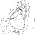
- FIG. 1 illustrates an example implantable leadless cardiac pacing device 10 (e.g., a leadless pacemaker) implanted in a chamber of a heart H, such as the right ventricle RV.
- the implantable device 10 may include a shell or housing 12 having a proximal end 14 and a distal end 16.
- the implantable device 10 may include a first electrode 20 positioned adjacent to the distal end 16 of the housing 12 and a second electrode 22 positioned adjacent to the proximal end 14 of the housing 12.
- housing 12 may include a conductive material and may be insulated along a portion of its length. A section along the proximal end 14 may be free of insulation so as to define the second electrode 22.
- the electrodes 20, 22 may be sensing and/or pacing electrodes to provide electro-therapy and/or sensing capabilities.
- the first electrode 20 may be capable of being positioned against or may otherwise contact the cardiac tissue of the heart H while the second electrode 22 may be spaced away from the first electrode 20, and thus spaced away from the cardiac tissue.
- the implantable device 10 may include a pulse generator (e.g., electrical circuitry) and a power source (e.g., a battery) within the housing 12 to provide electrical signals to the electrodes 20, 22 and thus control the pacing/sensing electrodes 20, 22. Electrical communication between the pulse generator and the electrodes 20, 22 may provide electrical stimulation to heart tissue and/or sense a physiological condition.
- a pulse generator e.g., electrical circuitry
- a power source e.g., a battery
- the implantable device 10 may include a fixation mechanism 24 proximate the distal end 16 of the housing 12 configured to attach the implantable device 10 to a tissue wall of the heart H, or otherwise anchor the implantable device 10 to the anatomy of the patient.
- the fixation mechanism 24 may include one or more, or a plurality of hooks 26 anchored into the cardiac tissue of the heart H to attach the implantable device 10 to a tissue wall.
- the fixation mechanism 24 may include one or more, or a plurality of passive tines, configured to entangle with trabeculae within the chamber of the heart H and/or a helical fixation anchor configured to be screwed into a tissue wall to anchor the implantable device 10 to the heart H.
- the implantable device 10 may include a docking member 30 proximate the proximal end 14 of the housing 12 configured to facilitate delivery and/or retrieval of the implantable device 10.
- the docking member 30 may extend from the proximal end 14 of the housing 12 along a longitudinal axis of the housing 12.
- the docking member 30 may include a head portion 32 and a neck portion 34 extending between the housing 12 and the head portion 32.
- the head portion 32 may be an enlarged portion relative to the neck portion 34.
- the head portion 32 may have a radial dimension from the longitudinal axis of the implantable device 10 which is greater than a radial dimension of the neck portion from the longitudinal axis of the implantable device 10.
- the docking member 30 may be configured to facilitate delivery of the implantable device 10 to the intracardiac site and/or retrieval of the implantable device 10 from the intracardiac site.
- Other docking members 30 are contemplated.
- the delivery device may need to be navigated through relatively tortuous anatomy to deliver the device 10 to a suitable location, for instance, in some embodiments, the delivery device may be advanced through the vasculature to a target region.
- the device may be advanced through a femoral vein, into the inferior vena cava, into the right atrium, through the tricuspid valve, and into the right ventricle.
- the target region for the delivery of the device 10 may be a portion of the right ventricle, for example, a portion of the right ventricle near the apex of the heart.
- the target region may also include other regions of the heart (e.g., right atrium, left atrium, or left ventricle), blood vessels, or other suitable targets. It may be desirable to provide the delivery system with certain features that may allow for easier or better control for navigation or delivery purposes.
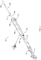
- FIG 2 is a perspective view of an illustrative delivery device 100, such as a catheter, that may be used to deliver the device 10.
- the delivery device 100 may include an outer tubular member 102 having a proximal section 104 and a distal section 106.
- An inner tubular member 110 may be slidably disposed within a lumen 150 of the outer tubular member 102 (see e.g. Figures 3 and 4 ).
- a distal holding section 108 may be attached to a distal end portion 114 of the inner tubular member 110.
- the delivery device 100 may also include a handle assembly 120 positioned adjacent to the proximal section of the outer tubular member 102.
- the outer tubular member 102 may include at least a section thereof that has an outer diameter D2 that is less than the outer diameter D1 of at least a portion of the holding section 108 (see e.g. Figure 3 ).
- the handle assembly 120 may include a first or distal hub portion 126 attached to the proximal end section 104 of the outer tubular member 102, a second or intermediate hub portion 128 attached to a proximal end section of the inner tubular member 110, and a third or proximal hub portion 130 attached to a proximal end section of a push member 116 (see e.g. Figure 3 ).
- the first hub portion 126, second hub portion 128, and third hub portion 130 may be positioned in a generally telescoping arrangement and slidable relative to each other.
- each of the first hub portion 126, the second hub portion 128, and the third hub portion 130 may be slidable and rotatable relative to each other such that the outer tubular member 102, inner tubular member 110, and push member 116 may be individually actuated. In some instances, it may be desirable to move the outer tubular member 102, inner tubular member 110 and push member 116 simultaneously.
- the handle assembly 120 may include a first locking mechanism 132 to releasably couple the outer tubular member 102 to the inner tubular member 110, as will be discussed in more detail below.
- the handle assembly 120 may also include a second locking mechanism 134 to releasably couple the inner tubular member 110 to the push member 116, as will be discussed in more detail below.
- the distal holding section 108 may be configured to receive the implantable device 10 therein.
- the holding section 108 may define a cavity 142 for slidably receiving the implantable device 10, and may include a distal opening 144 for slidable insertion and/or extraction of the implantable device 10 into and/or out of the cavity 142.
- the distal holding section 108 may include a body portion 138 and a distal tip portion 140 that may be, for example, configured to be atraumatic to anatomy, such as a bumper tip.
- atraumatic to anatomy such as a bumper tip.
- the distal tip may come into contact with anatomy.
- tissue adjacent the target cite e.g. cardiac tissue of the heart.
- a hard distal tip formed of the material of the outer tubular member 102 and/or inner tubular member 110 may injure a vessel wall or cardiac tissue.
- the distal tip 140 may be made of a material that is softer than the body portion 138 of the distal holding section.
- the distal tip 140 may include a material that has a durometer that is less than the durometer of the material of the body portion 138.
- the durometer of the material used in the distal tip 140 may be in the range of about 5 D to about 70 D, or for example, in the range of about 25 D to about 65 D.
- the distal tip 140 may include a shape or structure that may make it less traumatic to tissue.
- the distal tip 140 may have a distal surface, such as a tissue contacting surface, that is that is rounded or includes a curvature configured to be more atraumatic to tissue.
- the distal holding section 108 may include an inner surface that may be configured to resist getting caught on the fixation mechanism 24, such as the one or more, or a plurality of hooks 26 on the device 10.
- the distal holding section 108 may include an inner layer or coating of harder or more lubricious material that resists force applied by the fixation mechanism 24 onto the inner surface of the distal holding section 108.
- the distal holding section 108 may include a multi-layered structure, and an inner layer may be made of a material that is harder than an outer layer.
- a push member 116 may be disposed (e.g., slidably disposed) within a lumen 152 of the inner tubular member 110.
- the push member 116 may be engaged by a user near or at the third hub portion 130, and extend through a lumen 152 of the inner tubular member 110 and into the distal holding section 108.
- a distal portion 118 of the push member 116 may be capable of engaging the device 10, and the push member 116 may be used to "push" the device 10 out from distal holding section 108 so as to deploy and anchor device 10 within a target region (e.g., a region of the heart such as the right ventricle).
- a target region e.g., a region of the heart such as the right ventricle
- the delivery device 100 may be configured to be deflectable or articulable or steerable.
- the outer tubular member 102 and/or inner tubular member 110 may include one or more articulation or deflection mechanism(s) that may allow for the catheter 1 00, or portions thereof, to be deflected, articulated, steered and/or controlled in a desired manner.
- the outer tubular member 102 may include at least a portion thereof that can be selectively bent and/or deflected in a desired or predetermined direction.
- This may, for example, allow a user to orient the delivery device 1 00 such that the holding section 108 is in a desirable position or orientation for navigation or delivery of the device 10 to a target location.
- the outer tubular member 102 may be deflected, for example, along a deflection region.
- deflection may be effected by one or more actuation members, such as pull wire(s) extending between a distal portion of the outer tubular member 102 and an actuation mechanism 122 near the proximal end of the outer tubular member 102.
- the one or more pull wires may extend both proximally and distally of the desired deflection or bending region or point. This allows a user to actuate (e.g., "pull") one or more of the pull wires to apply a compression and/or deflection force to at least a portion of the outer tubular member 102 and thereby deflect or bend the outer tubular member 102 in a desired manner.
- the one or more wires may be stiff enough so that they can also be used to provide a pushing and/or tensioning force on the outer tubular member 102, for example, to "push” or “straighten” the shaft into a desired position or orientation.
- the actuation member takes the form of a continuous wire that is looped through or otherwise coupled to a distal end region of the outer tubular member 102 so as to define a pair of wire sections.
- the actuation member includes one or a plurality of individual wires that are attached, for example, to a metal or metal alloy ring adjacent the distal end region of the outer tubular member 102.
- the actuation mechanism 122 may include a desired mechanism that may allow for applying tension (i.e. pulling force), or compression (i.e. pushing force), or both, on the actuation member(s).
- the actuation mechanism 122 may include an external rotatable member 124 connected to and rotatable about the longitudinal axis of the handle assembly 120.
- the rotatable member 1 24 may threadingly engage an internal member that is attached to the proximal end of the actuation member(s) or pull wires.
- the internal member When the external rotatable member 124 is rotated in a first rotational direction, the internal member translates in a first longitudinal direction, thereby applying tension to the pull wires, which applies compression force to the shaft, so as to deflect the outer tubular member 102 from an initial position to a deflected position.
- the external rotatable member 124 When the external rotatable member 124 is rotated in a second rotational direction, the internal member translates in a second longitudinal direction, thereby releasing the tension on the pull wires, and allowing the outer tubular member 102 to relax back toward the initial position.
- rotation of the rotatable member 124 in the second rotational direction such that the internal member translates in a second longitudinal direction may apply compression to the wires, such that the wires may apply tension to the outer tubular member 102 and "push" the outer tubular member 102 back toward an initial position, and possibly into additional positions beyond the initial position.
- the one or more articulation and/or deflection mechanism(s) may also entail the outer tubular member 102 including structure and/or material that may provide for the desired degree and/or location of the deflection when the compressive or tensile forces are applied.
- the outer tubular member 102 may include one or more sections that include structure and/or material configured to allow the shaft to bend and/or deflect in a certain way when a certain predetermined compressive and/or tensile force is applied.
- the shaft may include one or more sections that are more flexible than other sections, thereby defining a bending or articulating region or location. Some such regions may include a number of varying or changing flexibility characteristics that may define certain bending shapes when predetermined forces are applied. Such characteristics may be achieved through the selection of materials or structure for different sections of the outer tubular member 102.
- all or a portion of the delivery device 100 such as the outer tubular member 102, may be made of a shape memory material, such as a shape memory polymer and/or a shape memory metal.
- a shape memory material such as a shape memory polymer and/or a shape memory metal.
- Such materials when stimulated by an actuation mechanism, such as a change in temperature or the application of an electrical current, may change or move from a first shape to a second shape.
- these material and mechanism may be used to deflect or bend the outer tubular member 102 in a desired manner.
- Other suitable deflection mechanism(s) that are able to deflect the delivery device 100 may also be used.
- Such alternative mechanisms may be applied to all other embodiments shown and/or discussed herein, and others, as appropriate.
- the outer tubular member 102 may include one or more predefined or fixed curved portion(s) along the length thereof.
- such curved sections may be configured to fit with particular anatomies or be configured for better navigation or delivery of the device 10. Additionally, or alternatively, some such curved sections may be configured to allow the outer tubular member 102 to be predisposed to be bent and/or deflected in a certain direction or configuration when compression and/or tension forces are applied thereto.
- the distal holding section 108 may be affixed to a distal end portion 114 of the inner tubular member 110.
- the distal holding section 108 may include a hub portion 136 and a tubular body portion 138.
- the hub portion 136 may be formed from a metal or metal alloy while the body portion 138 may be formed from a polymeric material, although this is not required.
- a proximal region 143 of the body portion 138 may be heat bonded to a distal end portion 137 of the hub portion 136, or otherwise affixed. As the body portion 138 is heated, the body portion 138 may reflow into grooves 141 in the distal end portion 137.
- the hub portion 136 may include a tapered intermediate region 145 disposed between a proximal end portion 139 and the distal end portion 137.
- the outer tubular member 102 may include a metal ring or tip adjacent the distal end 103 thereof for attaching one or more pull wires thereto. It is contemplated that the outer tubular member 102 may further include a lubricious liner, such as, but not limited to a polytetrafluoroethylene (PTFE) liner.
- PTFE polytetrafluoroethylene
- the proximal end portion 139 of the hub portion 136 may extend proximally into the lumen 150 of the outer tubular member 102. In some instances, an outer surface of the proximal end portion 139 may form an interference fit with an inner surface of the outer tubular member 102.
- the outer surface of the proximal end portion 139 and the inner surface of the outer tubular member 102 may be coupled in a tapered engagement.
- the distal end 103 of the outer tubular member 102 may flare radially outwards in the distal direction and/or the proximal end portion 139 may taper radially inward in the proximal direction.
- the two angled surface may engage as the proximal end portion 139 is proximally retracted within the outer tubular member 102.
- Other coupling arrangements may be used as desired.
- Figure 3A illustrates a partial cross-sectional view of an alternative mechanism for coupling the outer tubular member 102a to the proximal end 139a of the hub portion 136a. Some components have been removed for clarity.
- the outer tubular member 102a and the hub portion 136a may be similar in form and function to the outer tubular member 102 and the hub portion 136 described above. In some instances, the outer tubular member 102a and the proximal end portion 139a may be coupled through a threaded engagement.
- the outer tubular member 102a may include a first helical flange or threaded portion 125a and the proximal end portion 139a may include a second helical flange or threaded portion 127a configured to mate with and/or threadably engage the helical flange or threaded portion 125a on the outer tubular member 102a. It is contemplated that the outer tubular member 102a and/or the hub portion 136a may be rotated in a first direction causing helical flanges or threaded portions 125a, 127a to engage. Rotation of the outer tubular member 102a and/or the hub portion 136a in a second direction opposite the first direction may cause the helical flanges or threaded portions 125a, 127a to disengage.
- Figure 3B illustrates a partial cross-sectional view of an alternative mechanism for coupling the outer tubular member 102b to the proximal end 139b of the hub portion 136b.
- the outer tubular member 102b and the hub portion 136b may be similar in form and function to the outer tubular member 102 and the hub portion 136 described above.
- the coupling arrangement may include a snap lock, a tongue and groove type lock, a mating detent and groove or other features configured to engage a corresponding feature on the outer tubular member 102b and/or the proximal end portion 139b.
- the outer tubular member 102b may include a groove or recess 121b disposed in an inner wall thereof.
- the proximal end 139b may include a protrusion, bump, or other extending feature 123b configured to mate or engage with the recess 121b in the outer tubular member 102b. It is contemplated that the protrusion 123b and the groove 121b may be disengaged through application of an external force (e.g., axial force) such as proximal retraction of the outer tubular member 102b and/or distal actuation of the hub portion 136b.
- an external force e.g., axial force
- Figure 3C illustrates a perspective view of another alternative mechanism for coupling the outer tubular member 102c to the proximal end 139c of the hub portion 136c.
- the outer tubular member 102c and the hub portion 136c may be similar in form and function to the outer tubular member 102 and the hub portion 136 described above.
- the outer tubular member 102c and the proximal end portion 139c may be coupled through a bayonet style locking feature. It is contemplated that a generally "L" shaped groove 190c may be formed in the proximal end 139c of the hub portion 136c.
- the outer tubular member 102c may include a protrusion 188c extending radially inward from an inner surface of the outer tubular member 102c.
- the "L" shaped groove 190c and the protrusion 188c may be configured to releasably engage one another in a manner similar the locking mechanism 132 described with respect to Figures 6A-6E such that the outer tubular member 102 c and the proximal end 139c of the hub portion 136c may be releasably coupled.
- a generally "L" shaped groove may be formed in the distal end of the outer tubular member 102c and the proximal end 139c of the hub portion 136c may include a protrusion extending radially outward therefrom for mating engagement with the groove.
- the proximal end portion 139 may advance distally and disengage from the inner surface of the outer tubular member 102 creating a kink point or weakened region adjacent to the bonding region 146. Proximally retracting the inner tubular member 110 to bring the intermediate region 145 into contact with the outer tubular member 102 at contact point 148 and/or bringing the proximal end portion 139 into the outer tubular member 102 and fixing the inner tubular member 110 in this configuration may help prevent migration of the distal holding section 108 during navigation of the device 100 to the desired location.
- Such a configuration may also place the inner tubular member 110 in tension while the distal holding section 108 applies a compression force on the outer tubular member 102, as will be discussed in more detail below.
- a locking mechanism 132 in the handle assembly 120 may be utilized to releasably maintain the outer tubular member 102 and the inner tubular member 110 in a desired orientation.
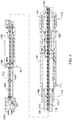
- Figure 4 illustrates a cross-sectional view of the handle assembly 120 of the delivery device.
- the handle assembly 120 may include a first hub portion 126 attached to the proximal end section 104 of the outer tubular member 102, a second hub portion 128 attached to a proximal end section of the inner tubular member 110, and a third hub portion 130 attached to a proximal end section of a push member 116.
- Each of the first hub portion 126, the second hub portion 128, and the third hub portion 130 may be slidable and rotatable relative to each other such that the outer tubular member 102, inner tubular member 110, and push member 116 may be individually actuated.
- the push member 116 may extend distally from a proximal end 117.
- the proximal end 117 of the push member 116 may be positioned within or adjacent to a valve member 113.
- the valve member 113 may be in fluid communication with a lumen 154 of the push member 116.
- the lumen 154 may extend from the proximal end 117 to the distal portion 118 for delivering fluids, such as, but not limited to, a contrast and/or flushing fluid to the cavity 142 of the distal holding section 108.
- the push member 116 may be coupled or affixed to the third hub portion 130 adjacent the proximal end 117 of the push member 116, although this is not required.
- the push member 116 may be affixed to the third hub portion 130 at any longitudinal location desired.
- a tether (not explicitly shown) for securing the implantable device 10 to the distal portion 118 of the push member 116 may be disposed within the lumen 154 and may exit the device 100 through valve member 113, although this is not required.
- the inner tubular member 110 may extend distally from a proximal end 112.
- the proximal end 112 of the inner tubular member 110 may be positioned within the second hub portion 128.
- the inner tubular member 110 may include a lumen 152 extending from the proximal end 112 to a distal end of the inner tubular member 110.
- the push member 116 may be slidably disposed within the lumen 152 of the inner tubular member 110.
- the inner tubular member 110 may be coupled or affixed to the second hub portion 128 adjacent the proximal end 112 of the push inner tubular member 110, although this is not required. It is contemplated that the inner tubular member 110 may be affixed to the second hub portion 128 at any longitudinal location desired.
- the outer tubular member 102 may extend distally from a proximal end 105.
- the proximal end 105 of the outer tubular member 102 may be positioned within the first hub portion 126.
- the outer tubular member 102 may include a lumen 150 extending from the proximal end 105 to a distal end 103 of the outer tubular member 102.
- the inner tubular member 110 may be slidably disposed within the lumen 150 of the outer tubular member 102.
- the outer tubular member 102 may be coupled or affixed to the first hub portion 126 adjacent the proximal end 105 of the outer tubular member 102, although this is not required. It is contemplated that the outer tubular member 102 may be affixed to the first hub portion 126 at any longitudinal location desired.
- the first hub portion 126 may include a retaining ring 158 positioned adjacent to a proximal end of the first hub portion 1 26. In some instances, the retaining ring 158 may be rotatable about a longitudinal axis of the handle assembly 120. It is further contemplated that the retaining ring 158 may include locking features configured to engage with other locking features of the locking mechanism 132.
- the second hub portion 128 may include a retaining ring 164 positioned adjacent to a proximal end of the second hub portion 128. In some instances, the retaining ring 164 may be rotatable about a longitudinal axis of the handle assembly 120. It is further contemplated that the retaining ring 164 may include locking features configured to engage with other locking features of the locking mechanism 134.
- Figure 5 illustrates a partial perspective view of handle assembly 120 with portions of the first hub portion 126 removed to more clearly illustrate features of the first locking mechanism 132, which may releasably couple the first hub portion and the second hub portion and/or the outer tubular member 102 and the inner tubular member 110.
- the locking mechanism 132 may be a bayonet style locking feature. It is contemplated that a generally "L" shaped groove 156 may be formed in the second hub portion 128 adjacent a distal end 129 of the second hub portion 128.
- the retaining ring 158 may include a protrusion 162 (schematically represented in Figures 6A-6E ) extending radially inward from an inner surface of the retaining ring 158.
- the retaining ring 158, and the first hub portion 126 may have an inner diameter generally larger than an outer diameter of the second hub portion 128 such that the second hub portion 128 can be proximally retracted 168 and distally advanced 170 within a lumen of the first hub portion 126.
- the second hub portion 128 may be rotated 172 relative to the first hub portion 126 about the longitudinal axis of the handle assembly 120 to align the protrusion 162 with a first or vertical portion 157 of the groove 156 as shown in Figure 6A .
- the use of “vertical” and “horizontal” are not intended to be limiting rather to provide relative movements of interacting components.
- the first hub portion 126, or components thereof may be rotated relative to the second hub portion 128.
- the second hub portion 128 may be proximally retracted 168 to advance the protrusion 162 further into the groove 156 as indicated at arrow 174.
- the second hub portion 128 may be rotated in a first direction to advance the protrusion 162 along a second or horizontal portion 159 of the groove 156 generally orthogonal to the vertical portion 157 towards a dip, recess, or serif 160 positioned at an end of the horizontal portion 159 as shown at arrow 178 in Figure 6B .
- a wall 180 may provide a stopping mechanism adjacent to the serif 160. Once the protrusion 162 has engaged the stopping mechanism 180, the second hub portion 128 may be advanced distally 170 to secure the protrusion 162 within the serif 160, as shown in Figure 6C .
- the serif 160 may help prevent accidental rotation of the retaining ring 158 and thus accidental uncoupling of the outer tubular member 102 and the inner tubular member 110.
- the distal end 129 of the second hub portion 128 may extend distally beyond the protrusion 162 and the retaining ring 158. Proximally retracting the second hub portion 128 (secured to the inner tubular member 110) relative to the first hub portion 126 (secured to the outer tubular member 102) to engage the protrusion 162 and the serif 160 may place the inner tubular member 110 in tension.
- a tensile force in the range of about 1 - 3 pounds-force (about 4.4 - 13.3 Newtons) or approximately less than 2 pounds-force (approximately less than 8.9 Newtons) may be applied to the inner tubular member 110.
- the hub portion 136 of the distal holding section 108 may apply a proximal force on the distal end of the outer tubular member 102 thus placing the outer tubular member 102 under compression.
- This configuration may allow the multiple shaft delivery device 100 to behave like a single shaft delivery device.
- placing the inner tubular member 110 in tension may account for a shorter path length of the outer tubular member 102 at bends in the delivery device 100.
- a first side of the tube wall may have a first arc radius and a second side of the tube wall, opposite first side of the tube wall, may have a second arc radius smaller than the first arc radius.
- the inner tubular member 110 may contact the first side of the tube wall of the outer tubular member 102. This may place a biasing force against the outer tubular member 102 in a direction other than the desired curve.
- the position of the inner tubular member 110 within the lumen 150 of the outer tubular member 102 may be brought closer the second side of the tube wall. This may facilitate steering of the device 100 to the desired location by reducing the forces applied on the outer tubular member 102. Additionally, actuation of either of the outer tubular member 102 or the inner tubular member 110 may result in the actuation of both the outer tubular member 102 and the inner tubular member 110. It is further contemplated that when the inner tubular member 110 and the outer tubular member 102 are in a coupled configuration, the distal holding section 108 may not move distally out of engagement with the outer tubular member 102.
- the second hub portion 128 When a user desires to uncouple the outer tubular member 102 and the inner tubular member 110, the second hub portion 128 may be distally advanced 170 to disengage the protrusion 162 from the serif 160. The second hub portion 128 may then be rotated 172 relative to the first hub portion 126 about the longitudinal axis of the handle assembly 120 in a direction opposite to the direction used to couple the outer tubular member 102 and the inner tubular member 110 as indicated at arrow 182 in Figure 6D . The second hub portion 128 may be rotated in a second direction, generally opposite to the first direction, to advance the protrusion 162 along the horizontal portion 159 of the groove 156 towards the vertical portion 157 as shown at arrow 182 in Figure 6D .
- a wall 184 may provide a stopping mechanism adjacent to the vertical portion 157. Once the protrusion 162 has engaged the stopping mechanism 184, the second hub portion 128 may be advanced distally 170 to disengage the protrusion 1 62 from the mating groove 156, as shown at arrow 186 in Figure 6E . It is further contemplated that the outer surface of the retaining ring 158, the first hub portion 126, and/or the second hub portion 128 may be provided with visual markings to assist the user locking and/or unlocking the locking mechanism 132. It is further contemplated that in some instances, the "L" shaped groove may be positioned on the retaining ring 158 or first hub portion 126 and the protrusion 162 may be positioned on the second hub portion 128. Furthermore, while the first locking mechanism 132 has been described as a bayonet style locking mechanism other locking mechanisms capable of releasably securing the outer tubular member 102 and the inner tubular member 110 are contemplated.
- the locking mechanism 132 may be formed in a similar manner to a quick connect locking mechanism commonly used in plumbing applications.
- a quick connect locking mechanism may utilize an o-ring and a compression fit to maintain a fluid tight seal.
- a rotating locking ring may maintain the quick connect locking mechanism in a locked configuration.
- the locking mechanism 132 may include a threaded engagement similar to the threaded engagement described above with respect to Figure 3A .
- the retaining ring 158 or other portion of the first hub portion 126 may include a first threaded region and the second hub portion 128 may include a second threaded region configured to mate with and/or threadably engage the threaded region on the retaining ring 1 58 or other portion of the first hub portion 126.
- the locking mechanism 132 may include a snap lock, a tongue and groove type lock, a mating detent and groove or other features configured to engage a corresponding feature on the retaining ring 158 and/or second hub portion 128 similar to the coupling arrangement described above with respect to Figure 3B .
- Figure 7 illustrates another partial perspective view of handle assembly 120 with portions of the second hub portion 128 removed to more clearly illustrate features of the second locking mechanism 134, which may be used to releasably couple the inner tubular member 110 and the push member 116.
- the locking mechanism 134 may be a bayonet style locking feature. It is contemplated that a generally "L" shaped groove 166 may be formed in the third hub portion 130 adjacent a distal end 131 of the third hub portion 130.
- the retaining ring 164 may include a protrusion, which may be similar in form and function to the protrusion 162 described with respect to Figures 5 and 6A-6E , extending radially inward from an inner surface of the retaining ring 164.
- the retaining ring 164, and the second hub portion 128, may have an inner diameter generally larger than an outer diameter of the third hub portion 130 such that the third hub portion 130 can be proximally retracted 168 and distally advanced 170 within a lumen of the second hub portion 128.
- the second locking mechanism 134 may function in a similar manner to the first locking mechanism 132 described above.
- the third hub portion 130 may be rotated 172 relative to the second hub portion 128 in a first direction about the longitudinal axis of the handle assembly 120 to align the protrusion with a first or vertical portion 165 of the groove 166.
- the use of “vertical” and “horizontal” are not intended to be limiting rather to provide relative movements of interacting components.
- the second hub portion 128, or components thereof may be rotated relative to the third hub portion 128
- the third hub portion 130 may be proximally retracted 168 to advance the protrusion further into the groove 166.
- the third hub portion 130 may be rotated to advance the protrusion along a second or horizontal portion 167 of the groove 166 generally orthogonal to the vertical portion 165 towards a dip or serif 169 positioned at an end of the horizontal portion 167.
- a wall 173 may provide a stopping mechanism adjacent to the serif 169. Once the protrusion has engaged the stopping mechanism 173, the third hub portion 130 may be advanced distally 170 to secure the protrusion within the serif 169.
- the serif 169 may help prevent accidental rotation of the retaining ring 164 and thus accidental uncoupling of the inner tubular member 110 and the push member 116.
- the distal end 131 of the third hub portion 130 may extend distally beyond the protrusion and the retaining ring 164.
- Proximally retracting the third hub portion 130 (secured to the push member 116) relative to the second hub portion 128 (secured to the inner tubular member 110) to engage the protrusion and the serif 169 may place the push member 116 in tension. It is contemplated that placing the push member 116 in tension may account for a shorter path length at bends in the delivery device 100.
- the third hub portion 130 may be distally advanced 170 to disengage the protrusion from the serif 169.
- the third hub portion 130 may then be rotated 172 relative to the second hub portion 128 in a second direction, generally opposite the first direction, about the longitudinal axis of the handle assembly 120.
- the third hub portion 130 may be rotated to advance the protrusion along the horizontal portion 167 of the groove 166 towards the vertical portion 165.
- a wall 175 may provide a stopping mechanism adjacent to the vertical portion 165. Once the protrusion has engaged the stopping mechanism 175, the third hub portion 130 may be advanced distally 170 to disengage the protrusion from the mating groove 166.
- the outer surface of the retaining ring 164, second hub portion 128, and/or the third hub portion 130 may be provided with visual markings to assist the user locking and/or unlocking the locking mechanism 134. It is further contemplated that in some instances, the "L" shaped groove may be positioned on the retaining ring 164 or second hub portion 128 and the protrusion may be positioned on the third hub portion 130. Furthermore, while the second locking mechanism 134 has been described as a bayonet style locking mechanism other locking mechanisms capable of releasably securing the inner tubular member 110 and the push member 116 are contemplated.
- the locking mechanism 134 may be formed in a similar manner to a quick connect locking mechanism commonly used in plumbing applications.
- a quick connect locking mechanism may utilize an o-ring and a compression fit to maintain a fluid tight seal.
- a rotating locking ring may maintain the quick connect locking mechanism in a locked configuration.
- the locking mechanism 134 may include a threaded engagement similar to the threaded engagement described above with respect to Figure 3A .
- the retaining ring 164 or other portion of the second hub portion 128 may include a first threaded region and the third hub portion 130 may include a second threaded region configured to mate with and/or threadably engage the threaded region on the retaining ring 164 or other portion of the second hub portion 128.
- the locking mechanism 134 may include a snap lock, a tongue and groove type lock, a mating detent and groove or other features configured to engage a corresponding feature on the retaining ring 164 and/or third hub portion 130 similar to the coupling arrangement described above with respect to Figure 3B .
- the materials that can be used for the various components of the delivery devices, such as delivery device 100 (and/or other delivery structures disclosed herein) and the various members disclosed herein may include those commonly associated with medical devices.
- delivery device 100 and components of thereof.
- this is not intended to limit the devices and methods described herein, as the discussion may be applied to other similar delivery systems and/or components of delivery systems or devices disclosed herein.
- the delivery device 100 and/or other components of delivery system may be made from a metal, metal alloy, polymer (some examples of which are disclosed below), a metal-polymer composite, ceramics, combinations thereof, and the like, or other suitable material.
- suitable polymers may include polytetrafluoroethylene (PTFE), ethylene tetrafluoroethylene (ETFE), fluorinated ethylene propylene (FEP), polyoxymethylene (POM, for example, DELRIN® available from DuPont), polyether block ester, polyurethane (for example, Polyurethane 85A), polypropylene (PP), polyvinylchloride (PVC), polyether-ester (for example, ARNITEL® available from DSM Engineering Plastics), ether or ester based copolymers (for example, butylene/poly(alkylene ether) phthalate and/or other polyester elastomers such as HYTREL® available from DuPont), polyamide (for example, DURETHAN® available from Bay
- suitable metals and metal alloys include stainless steel, such as 304V, 304L, and 316LV stainless steel; mild steel; nickel-titanium alloy such as linear-elastic and/or super-elastic nitinol; other nickel alloys such as nickel-chromium-molybdenum alloys (e.g., UNS: N06625 such as INCONEL® 625, UNS: N06022 such as HASTELLOY® C-22®, UNS: N10276 such as HASTELLOY® C276®, other HASTELLOY® alloys, and the like), nickel-copper alloys (e.g., UNS: N04400 such as MONEL® 400, NICKELVAC® 400, NICORROS® 400, and the like), nickel-cobalt-chromium-molybdenum alloys (e.g., UNS: R30035 such as MP35-N® and the like), nickel-molybdenum alloys (e.g.,
- Linear elastic and/or non-super-elastic nitinol may be distinguished from super elastic nitinol in that the linear elastic and/or non-super-elastic nitinol does not display a substantial "superelastic plateau” or “flag region” in its stress/strain curve like super elastic nitinol does.
- linear elastic and/or non-super-elastic nitinol as recoverable strain increases, the stress continues to increase in a substantially linear, or a somewhat, but not necessarily entirely linear relationship until plastic deformation begins or at least in a relationship that is more linear that the super elastic plateau and/or flag region that may be seen with super elastic nitinol.
- linear elastic and/or non-super-elastic nitinol may also be termed "substantially" linear elastic and/or non-super-elastic nitinol.
- linear elastic and/or non-super-elastic nitinol may also be distinguishable from super elastic nitinol in that linear elastic and/or non-super-elastic nitinol may accept up to about 2-5% strain while remaining substantially elastic (e.g., before plastically deforming) whereas super elastic nitinol may accept up to about 8% strain before plastically deforming. Both of these materials can be distinguished from other linear elastic materials such as stainless steel (that can also can be distinguished based on its composition), which may accept only about 0.2 to 0.44 percent strain before plastically deforming.
- the linear elastic and/or non-super-elastic nickel-titanium alloy is an alloy that does not show any martensite/austenite phase changes that are detectable by differential scanning calorimetry (DSC) and dynamic metal thermal analysis (DMTA) analysis over a large temperature range.
- DSC differential scanning calorimetry
- DMTA dynamic metal thermal analysis
- the mechanical bending properties of such material may therefore be generally inert to the effect of temperature over this very broad range of temperature.
- the mechanical bending properties of the linear elastic and/or non-super-elastic nickel-titanium alloy at ambient or room temperature are substantially the same as the mechanical properties at body temperature, for example, in that they do not display a super-elastic plateau and/or flag region.
- the linear elastic and/or non-super-elastic nickel-titanium alloy maintains its linear elastic and/or non-super-elastic characteristics and/or properties.
- the linear elastic and/or non-super-elastic nickel-titanium alloy may be in the range of about 50 to about 60 weight percent nickel, with the remainder being essentially titanium. In some embodiments, the composition is in the range of about 54 to about 57 weight percent nickel.
- a suitable nickel-titanium alloy is FHP-NT alloy commercially available from Furukawa Techno Material Co. of Kanagawa, Japan. Some examples of nickel titanium alloys are disclosed in U.S. Patent Nos. 5,238,004 and 6,508,803 , which are incorporated herein by reference. Other suitable materials may include ULTANIUMTM (available from Neo-Metrics) and GUM METALTM (available from Toyota).
- a superelastic alloy for example a superelastic nitinol can be used to achieve desired properties.
- portions or all of the delivery device 100 and/or other components of delivery system may be doped with, made of, or otherwise include a radiopaque material.
- Radiopaque materials are understood to be materials capable of producing a relatively bright image on a fluoroscopy screen or another imaging technique during a medical procedure. This relatively bright image aids the user of the delivery device 100 in determining its location.
- Some examples of radiopaque materials can include, but are not limited to, gold, platinum, palladium, tantalum, tungsten alloy, polymer material loaded with a radiopaque filler, and the like. Additionally, other radiopaque marker bands and/or coils may also be incorporated into the design of the delivery device 100 to achieve the same result.
- a degree of Magnetic Resonance Imaging (MRI) compatibility is imparted into the delivery device 100.
- delivery device 100 or portions or components thereof may be made of a material that does not substantially distort the image and create substantial artifacts (i.e., gaps in the image). Certain ferromagnetic materials, for example, may not be suitable because they may create artifacts in an MRI image.
- the delivery device 100, or portions thereof may also include and/or be made from a material that the MRI machine can image.
- Some materials that exhibit these characteristics include, for example, tungsten, cobalt-chromium-molybdenum alloys (e.g., UNS: R30003 such as ELGILOY®, PHYNOX®, and the like), nickel-cobalt-chromium-molybdenum alloys (e.g., UNS: R30035 such as MP35-N® and the like), nitinol, and the like, and others.
- cobalt-chromium-molybdenum alloys e.g., UNS: R30003 such as ELGILOY®, PHYNOX®, and the like
- nickel-cobalt-chromium-molybdenum alloys e.g., UNS: R30035 such as MP35-N® and the like
- nitinol and the like, and others.
Description
- The present disclosure pertains to medical devices, and methods for manufacturing and/or using medical devices. More particularly, the present disclosure pertains to leadless cardiac devices and methods, such as leadless pacing devices and methods, and delivery devices and methods for such leadless devices.
- A wide variety of medical devices have been developed for medical use, for example, cardiac use. Some of these devices include catheters, leads, pacemakers, and the like, and delivery devices and/or systems used for delivering such devices. These devices are manufactured by any one of a variety of different manufacturing methods and may be used according to any one of a variety of methods. Of the known medical devices, delivery systems, and methods, each has certain advantages and disadvantages. There is an ongoing need to provide alternative medical devices and delivery devices as well as alternative methods for manufacturing and using medical devices and delivery devices.
- Document
US 2011/0251662 relates to a fixation device for retaining a leadless medical implant to tissue including an array of elongate tines having self-expanding distal portions. The fixation tines may be advanced between an implant body and an outer jacket to deploy the tines from a delivery configuration in which the tines are constrained by the outer jacket to an expanded configuration in which the distal end portions of the tines are released from the outer jacket. The implant and fixation device are contained within a sheath for delivery to the treatment site and a pusher within the sheath advances the fixation device relative to the implant body and deploys the tines. A distal end of the implant having an electrode may form a distal tip of the delivery system, and a potential implantation site may be tested prior to deployment of the fixation device to allow for easy repositioning of the implant. - This disclosure provides design, material, manufacturing method, and use alternatives for medical devices, including delivery devices.
- In a first example, a delivery device for delivering an implantable leadless pacing device may comprise an outer tubular member including a lumen extending from a proximal end to a distal end thereof, an inner tubular member including a lumen extending from a proximal end to a distal end thereof, the inner tubular member slidably disposed within the lumen of the outer tubular member, a distal holding section extending distally of a distal end of the inner tubular member, the distal holding section defining a cavity therein for receiving an implantable leadless pacing device, a handle assembly including at least a first hub portion affixed adjacent to the proximal end of the outer tubular member and intermediate second hub portion affixed adjacent to the proximal end of the inner tubular member, and a first locking mechanism disposed within the handle assembly, wherein the first locking mechanism is configured to releasably couple the first hub portion and the second hub portion.
- Alternatively or additionally to any of the examples above, in another example, the first locking mechanism may have a locked position and an unlocked position wherein the inner tubular member is held in tension in the locked position.
- Alternatively or additionally to any of the examples above, in another example, the outer tubular member may be held in compression in the locked position.
- Alternatively or additionally to any of the examples above, in another example, the first hub portion and the second hub portion may be individually slidable and rotatable when the first locking mechanism is in an unlocked configuration.
- Alternatively or additionally to any of the examples above, in another example, the first locking mechanism may be selected from the group of a snap lock, a threaded engagement, or a quick connect locking feature.
- Alternatively or additionally to any of the examples above, in another example, the first locking mechanism may comprise a bayonet style locking mechanism.
- Alternatively or additionally to any of the examples above, in another example, the second hub portion may comprise a groove positioned adjacent a distal end of the second hub portion , the groove configured to receive an inwardly extending protrusion of the first hub portion.
- Alternatively or additionally to any of the examples above, in another example, the groove may comprise a first portion, a second portion extending generally orthogonal to the first portion, and a serif positioned at an end of the second portion.
- Alternatively or additionally to any of the examples above, in another example, disposing the protrusion within the serif may releasably couple the outer tubular member and the inner tubular member such that longitudinal or rotational actuation of either of the outer tubular member or the inner tubular member results in corresponding actuation of both the outer tubular member and the inner tubular member.
- Alternatively or additionally to any of the examples above, in another example, disposing the protrusion within the serif may place the inner tubular member in tension and the outer tubular member in compression.
- Alternatively or additionally to any of the examples above, in another example, the device may further comprise a push member slidably disposed within the lumen of the inner tubular member.
- Alternatively or additionally to any of the examples above, in another example, the device may further comprise a third hub portion affixed adjacent to a proximal end of the push member.
- Alternatively or additionally to any of the examples above, in another example, the device may further comprise a second locking mechanism disposed within the handle assembly.
- Alternatively or additionally to any of the examples above, in another example, the third hub portion may be slidable and rotatable independent of either of the first hub portion or the second hub portion when the second locking mechanism is in an unlocked configuration.
- Alternatively or additionally to any of the examples above, in another example, longitudinal or rotational actuation of either of the inner tubular member or the push member may result in corresponding actuation of both the inner tubular member and the push member when the second locking mechanism is in a locked configuration.
- Alternatively or additionally to any of the examples above, in another example, a method of releasably coupling an outer tubular member affixed to a first hub portion to an inner tubular member affixed to a second hub portion of a delivery device may comprise rotating the second hub portion relative to the first hub portion, the first hub portion having an inwardly extending protrusion, to align the protrusion with a first portion of a groove on a distal portion of the second hub portion, proximally retracting the second hub portion to advance the protrusion into the first portion of the groove, rotating the second hub portion relative to the first hub portion about a longitudinal axis of the first hub portion to advance the protrusion along a second portion of the groove, the second portion of the groove extending generally orthogonal to the first portion of the groove, and disposing the protrusion within a serif positioned at an end of the second portion of the groove.
- Alternatively or additionally to any of the examples above, in another example, a delivery device for delivering an implantable leadless pacing device may comprise an outer tubular member including a lumen extending from a proximal end to a distal end thereof, an inner tubular member including a lumen extending from a proximal end to a distal end thereof, the inner tubular member slidably disposed within the lumen of the outer tubular member, a distal holding section extending distally of a distal end of the inner tubular member, the distal holding section defining a cavity therein for receiving an implantable leadless pacing device, a handle assembly including at least a first hub portion affixed adjacent to the proximal end of the outer tubular member and a second hub portion affixed adjacent to the proximal end of the inner tubular member, and a first locking mechanism disposed within the handle assembly, wherein the first locking mechanism is configured to releasably couple the first hub portion and the second hub portion.
- Alternatively or additionally to any of the examples above, in another example, the first locking mechanism may have a locked position and an unlocked position wherein the inner tubular member is held in tension in the locked position.
- Alternatively or additionally to any of the examples above, in another example, the outer tubular member may be held in compression in the locked position.
- Alternatively or additionally to any of the examples above, in another example, the first hub portion and the second hub portion may be individually slidable and rotatable when the first locking mechanism is in an unlocked configuration.
- Alternatively or additionally to any of the examples above, in another example, the first locking mechanism may comprise a bayonet style locking mechanism.
- Alternatively or additionally to any of the examples above, in another example, the second hub portion may comprise a groove positioned adjacent a distal end of the second hub portion, the groove configured to receive an inwardly extending protrusion of the first hub portion.
- Alternatively or additionally to any of the examples above, in another example, the groove may comprise a first portion, a second portion extending generally orthogonal to the first portion, and a serif positioned at an end of the second portion.
- Alternatively or additionally to any of the examples above, in another example, disposing the protrusion within the serif may releasably couple the outer tubular member and the inner tubular member such that longitudinal or rotational actuation of either of the outer tubular member or the inner tubular member results in corresponding actuation of both the outer tubular member and the inner tubular member.
- Alternatively or additionally to any of the examples above, in another example, disposing the protrusion within the serif may place the inner tubular member in tension and the outer tubular member in compression.
- Alternatively or additionally to any of the examples above, in another example, the device may further comprise a push member slidably disposed within the lumen of the inner tubular member.
- Alternatively or additionally to any of the examples above, in another example, the device may further comprise a third hub portion affixed adjacent to a proximal end of the push member.
- Alternatively or additionally to any of the examples above, in another example, the device may further comprise a second locking mechanism disposed within the handle assembly.
- Alternatively or additionally to any of the examples above, in another example, the third hub portion may be slidable and rotatable independent of either of the first hub portion or the second hub portion when the second locking mechanism is in an unlocked configuration.
- Alternatively or additionally to any of the examples above, in another example, the first locking mechanism may be selected from the group of a snap lock, a threaded engagement, or a quick connect locking feature.
- Alternatively or additionally to any of the examples above, in another example, longitudinal or rotational actuation of either of the inner tubular member or the push member may result in corresponding actuation of both the inner tubular member and the push member when the second locking mechanism is in a locked configuration.
- Alternatively or additionally to any of the examples above, in another example, a delivery device for delivering an implantable leadless pacing device may comprise an outer tubular member including a lumen extending from a proximal end to a distal end thereof, an inner tubular member including a lumen extending from a proximal end to a distal end thereof, the inner tubular member slidably disposed within the lumen of the outer tubular member, a push member having a proximal end and a distal end, the push member slidably disposed within the lumen of the inner tubular member, a distal holding section extending distally of a distal end of the inner tubular member, the distal holding section defining a cavity therein for receiving an implantable leadless pacing device, a handle assembly including a distal hub portion affixed adjacent to the proximal end of the outer tubular member, an intermediate hub portion affixed adjacent to the proximal end of the inner tubular member, and a proximal hub portion affixed adjacent to the proximal end of the push member, the distal hub portion, the intermediate hub portion, and the proximal hub portion arranged in a telescoping configuration such that each of the distal hub portion, intermediate hub portion, and proximal hub portion are capable of being longitudinally and rotationally actuated individually, and a first locking mechanism disposed between the distal hub portion and the intermediate hub portion, wherein the first locking mechanism is configured to releasably couple the distal hub portion and the intermediate hub portion.
- Alternatively or additionally to any of the examples above, in another example, the first locking mechanism may be user actuatable between an unlocked configuration and a locked configuration.
- Alternatively or additionally to any of the examples above, in another example, when in the locked configuration, the intermediate hub portion may be proximally retracted to place the inner tubular member in tension and the outer tubular member in compression.
- Alternatively or additionally to any of the examples above, in another example, a method of releasably coupling an outer tubular member affixed to a first hub portion and an inner tubular member affixed to a second hub portion of a delivery device may comprise rotating a the first hub portion in a first direction relative to the second hub portion, the first hub portion having an inwardly extending protrusion, to align the protrusion with a first portion of a groove on a distal portion of a second hub portion, advancing the protrusion into the first portion of the groove, rotating the second hub portion relative to the first hub portion and about a longitudinal axis of the first hub portion in a first direction to advance the protrusion along a second portion of the groove, the second portion of the groove extending generally orthogonal to the first portion of the groove, and disposing the protrusion within a serif positioned at an end of the second portion of the groove.
- Alternatively or additionally to any of the examples above, in another example, disposing the protrusion within the serif may releasably couple the inner tubular member and the outer tubular member such that longitudinal or rotational actuation of either of the outer tubular member or the inner tubular member results in corresponding actuation of both the outer tubular member and the inner tubular member.
- Alternatively or additionally to any of the examples above, in another example, the method may further comprise disengaging the protrusion from the serif, rotating the second hub portion relative to the first hub portion in a second direction, the second direction generally opposite to the first direction, to advance the protrusion along a second portion of the groove towards the first portion of the groove, and distally advancing the second hub portion to disengage the protrusion from the first portion of the groove, wherein disengaging the protrusion from the first portion of the groove uncouples the inner tubular member and the outer tubular member.
- The above summary of some embodiments is not intended to describe each disclosed embodiment or every implementation of the present disclosure. The Figures, and Detailed Description, which follow, more particularly exemplify some of these embodiments.
- The disclosure may be more completely understood in consideration of the following detailed description in connection with the accompanying drawings, in which:
-
Figure 1 is a plan view of an example leadless pacing device implanted within a heart; -
Figure 2 is a perspective view of an example delivery device for an implantable leadless cardiac pacing device; -
Figure 3 is a partial cross-sectional side view of the distal portion of the delivery device ofFigure 2 ; -
Figure 3A is a partial cross-sectional side view of a portion of a distal portion of another illustrative delivery device; -
Figure 3B is a partial cross-sectional side view of a portion of a distal portion of another illustrative delivery device; -
Figure 3C is a partial perspective view of a portion of a distal portion of another illustrative delivery device; -
Figure 4 is a cross-sectional side view of the proximal portion of the delivery device ofFigure 2 ; -
Figure 5 is a perspective view of the proximal portion of the delivery device ofFigure 2 with portions removed; -
Figures 6A-6E are a schematic view of a locking mechanism of the proximal portion of the delivery device ofFigure 2 ; and -
Figure 7 is a perspective view of the proximal portion of the delivery device ofFigure 2 with portions removed. - For the following defined terms, these definitions shall be applied, unless a different definition is given in the claims or elsewhere in this specification.
- All numeric values are herein assumed to be modified by the term "about," whether or not explicitly indicated. The term "about" generally refers to a range of numbers that one of skill in the art would consider equivalent to the recited value (i.e., having the same function or result). In many instances, the terms "about" may include numbers that are rounded to the nearest significant figure.
- The recitation of numerical ranges by endpoints includes all numbers within that range (e.g. 1 to 5 includes 1, 1.5, 2, 2.75, 3, 3.80, 4, and 5).
- As used in this specification and the appended claims, the singular forms "a", "an", and "the" include plural referents unless the content clearly dictates otherwise. As used in this specification and the appended claims, the term "or" is generally employed in its sense including "and/or" unless the content clearly dictates otherwise.
- It is noted that references in the specification to "an embodiment", "some embodiments", "other embodiments", etc., indicate that the embodiment described may include one or more particular features, structures, and/or characteristics. However, such recitations do not necessarily mean that all embodiments include the particular features, structures, and/or characteristics. Additionally, when particular features, structures, and/or characteristics are described in connection with one embodiment, it should be understood that such features, structures, and/or characteristics may also be used connection with other embodiments whether or not explicitly described unless clearly stated to the contrary.
- The following detailed description should be read with reference to the drawings in which similar structures in different drawings are numbered the same. The drawings, which are not necessarily to scale, depict illustrative embodiments and are not intended to limit the scope of the disclosure.
- Cardiac pacemakers provide electrical stimulation to heart tissue to cause the heart to contract and thus pump blood through the vascular system. Conventional pacemakers typically include an electrical lead that extends from a pulse generator implanted subcutaneously or sub-muscularly to an electrode positioned adjacent the inside or outside wall of the cardiac chamber. As an alternative to conventional pacemakers, self-contained or leadless cardiac pacemakers have been proposed. Leadless cardiac pacemakers are small capsules typically fixed to an intracardiac implant site in a cardiac chamber. The small capsule typically includes bipolar pacing/sensing electrodes, a power source (e.g. a battery), and associated electrical circuitry for controlling the pacing/sensing electrodes, and thus provide electrical stimulation to heart tissue and/or sense a physiological condition. The capsule may be delivery to the heart using a delivery device which may be advanced through a femoral vein, into the inferior vena cava, into the right atrium, through the tricuspid valve, and into the right ventricle. Accordingly, it may be desirable to provide delivery devices which facilitate advancement through the vasculature.
-
Figure 1 illustrates an example implantable leadless cardiac pacing device 10 (e.g., a leadless pacemaker) implanted in a chamber of a heart H, such as the right ventricle RV. Theimplantable device 10 may include a shell orhousing 12 having a proximal end 14 and adistal end 16. Theimplantable device 10 may include afirst electrode 20 positioned adjacent to thedistal end 16 of thehousing 12 and asecond electrode 22 positioned adjacent to the proximal end 14 of thehousing 12. For example,housing 12 may include a conductive material and may be insulated along a portion of its length. A section along the proximal end 14 may be free of insulation so as to define thesecond electrode 22. Theelectrodes first electrode 20 may be capable of being positioned against or may otherwise contact the cardiac tissue of the heart H while thesecond electrode 22 may be spaced away from thefirst electrode 20, and thus spaced away from the cardiac tissue. - The
implantable device 10 may include a pulse generator (e.g., electrical circuitry) and a power source (e.g., a battery) within thehousing 12 to provide electrical signals to theelectrodes sensing electrodes electrodes - The
implantable device 10 may include afixation mechanism 24 proximate thedistal end 16 of thehousing 12 configured to attach theimplantable device 10 to a tissue wall of the heart H, or otherwise anchor theimplantable device 10 to the anatomy of the patient. As shown inFigure 1 , in some instances, thefixation mechanism 24 may include one or more, or a plurality ofhooks 26 anchored into the cardiac tissue of the heart H to attach theimplantable device 10 to a tissue wall. In other instances, thefixation mechanism 24 may include one or more, or a plurality of passive tines, configured to entangle with trabeculae within the chamber of the heart H and/or a helical fixation anchor configured to be screwed into a tissue wall to anchor theimplantable device 10 to the heart H. - The
implantable device 10 may include adocking member 30 proximate the proximal end 14 of thehousing 12 configured to facilitate delivery and/or retrieval of theimplantable device 10. For example, the dockingmember 30 may extend from the proximal end 14 of thehousing 12 along a longitudinal axis of thehousing 12. The dockingmember 30 may include ahead portion 32 and aneck portion 34 extending between thehousing 12 and thehead portion 32. Thehead portion 32 may be an enlarged portion relative to theneck portion 34. For example, thehead portion 32 may have a radial dimension from the longitudinal axis of theimplantable device 10 which is greater than a radial dimension of the neck portion from the longitudinal axis of theimplantable device 10. The dockingmember 30 may be configured to facilitate delivery of theimplantable device 10 to the intracardiac site and/or retrieval of theimplantable device 10 from the intracardiac site.Other docking members 30 are contemplated. - One aspect of the current disclosure relates to the delivery device and/or system used, for example, to deliver
device 10 to a suitable location within the anatomy (e.g., the heart). As may be appreciated, the delivery device may need to be navigated through relatively tortuous anatomy to deliver thedevice 10 to a suitable location, For instance, in some embodiments, the delivery device may be advanced through the vasculature to a target region. In some example cases the device may be advanced through a femoral vein, into the inferior vena cava, into the right atrium, through the tricuspid valve, and into the right ventricle. The target region for the delivery of thedevice 10 may be a portion of the right ventricle, for example, a portion of the right ventricle near the apex of the heart. The target region may also include other regions of the heart (e.g., right atrium, left atrium, or left ventricle), blood vessels, or other suitable targets. It may be desirable to provide the delivery system with certain features that may allow for easier or better control for navigation or delivery purposes. -
Figure 2 is a perspective view of anillustrative delivery device 100, such as a catheter, that may be used to deliver thedevice 10. Thedelivery device 100 may include an outertubular member 102 having aproximal section 104 and adistal section 106. An innertubular member 110 may be slidably disposed within a lumen 150 of the outer tubular member 102 (see e.g.Figures 3 and4 ). Adistal holding section 108 may be attached to a distal end portion 114 of the innertubular member 110. Thedelivery device 100 may also include ahandle assembly 120 positioned adjacent to the proximal section of the outertubular member 102. In some embodiments, the outertubular member 102 may include at least a section thereof that has an outer diameter D2 that is less than the outer diameter D1 of at least a portion of the holding section 108 (see e.g.Figure 3 ). - The
handle assembly 120 may include a first ordistal hub portion 126 attached to theproximal end section 104 of the outertubular member 102, a second orintermediate hub portion 128 attached to a proximal end section of the innertubular member 110, and a third orproximal hub portion 130 attached to a proximal end section of a push member 116 (see e.g.Figure 3 ). Thefirst hub portion 126,second hub portion 128, andthird hub portion 130 may be positioned in a generally telescoping arrangement and slidable relative to each other. As will be discussed in more detail below, each of thefirst hub portion 126, thesecond hub portion 128, and thethird hub portion 130 may be slidable and rotatable relative to each other such that the outertubular member 102, innertubular member 110, and pushmember 116 may be individually actuated. In some instances, it may be desirable to move the outertubular member 102, innertubular member 110 and pushmember 116 simultaneously. Thehandle assembly 120 may include afirst locking mechanism 132 to releasably couple the outertubular member 102 to the innertubular member 110, as will be discussed in more detail below. Thehandle assembly 120 may also include asecond locking mechanism 134 to releasably couple the innertubular member 110 to thepush member 116, as will be discussed in more detail below. - The
distal holding section 108 may be configured to receive theimplantable device 10 therein. For example, referring toFigure 3 , which illustrates a cross-sectional view of a distal portion ofdelivery device 100, the holdingsection 108 may define acavity 142 for slidably receiving theimplantable device 10, and may include adistal opening 144 for slidable insertion and/or extraction of theimplantable device 10 into and/or out of thecavity 142. - The
distal holding section 108 may include abody portion 138 and adistal tip portion 140 that may be, for example, configured to be atraumatic to anatomy, such as a bumper tip. For example, as the catheter is navigated through the anatomy, the distal tip may come into contact with anatomy. Additionally, when the catheter is used to deliver the device, thetip 140 of thedelivery device 100 will likely come into contact with tissue adjacent the target cite (e.g. cardiac tissue of the heart). A hard distal tip formed of the material of the outertubular member 102 and/or innertubular member 110 may injure a vessel wall or cardiac tissue. As such, it may be desirable to provide thedelivery device 100 with a softerdistal tip 140 that can be introduced into the anatomy and come into contact with anatomy adjacent the target cite without causing unnecessary trauma. - For example, the
distal tip 140 may be made of a material that is softer than thebody portion 138 of the distal holding section. In some cases, thedistal tip 140 may include a material that has a durometer that is less than the durometer of the material of thebody portion 138. In some particular embodiments, the durometer of the material used in thedistal tip 140 may be in the range of about 5 D to about 70 D, or for example, in the range of about 25 D to about 65 D. Additionally, thedistal tip 140 may include a shape or structure that may make it less traumatic to tissue. For example, thedistal tip 140 may have a distal surface, such as a tissue contacting surface, that is that is rounded or includes a curvature configured to be more atraumatic to tissue. - In some embodiments, all or a portion of the
distal holding section 108 may include an inner surface that may be configured to resist getting caught on thefixation mechanism 24, such as the one or more, or a plurality ofhooks 26 on thedevice 10. For example, thedistal holding section 108 may include an inner layer or coating of harder or more lubricious material that resists force applied by thefixation mechanism 24 onto the inner surface of thedistal holding section 108. For example, thedistal holding section 108 may include a multi-layered structure, and an inner layer may be made of a material that is harder than an outer layer. - A
push member 116 may be disposed (e.g., slidably disposed) within alumen 152 of the innertubular member 110. Thepush member 116 may be engaged by a user near or at thethird hub portion 130, and extend through alumen 152 of the innertubular member 110 and into thedistal holding section 108. Adistal portion 118 of thepush member 116 may be capable of engaging thedevice 10, and thepush member 116 may be used to "push" thedevice 10 out fromdistal holding section 108 so as to deploy andanchor device 10 within a target region (e.g., a region of the heart such as the right ventricle). - In order to more specifically place or steer the
delivery device 100 to a position adjacent to the intended target, thedelivery device 100 may be configured to be deflectable or articulable or steerable. Referring toFigure 2 , for example, the outertubular member 102 and/or innertubular member 110 may include one or more articulation or deflection mechanism(s) that may allow for the catheter 1 00, or portions thereof, to be deflected, articulated, steered and/or controlled in a desired manner. For example, the outertubular member 102 may include at least a portion thereof that can be selectively bent and/or deflected in a desired or predetermined direction. This may, for example, allow a user to orient the delivery device 1 00 such that the holdingsection 108 is in a desirable position or orientation for navigation or delivery of thedevice 10 to a target location. The outertubular member 102 may be deflected, for example, along a deflection region. - A wide variety of deflection mechanisms may be used. In some example embodiments, deflection may be effected by one or more actuation members, such as pull wire(s) extending between a distal portion of the outer
tubular member 102 and anactuation mechanism 122 near the proximal end of the outertubular member 102. As such, the one or more pull wires may extend both proximally and distally of the desired deflection or bending region or point. This allows a user to actuate (e.g., "pull") one or more of the pull wires to apply a compression and/or deflection force to at least a portion of the outertubular member 102 and thereby deflect or bend the outertubular member 102 in a desired manner. In addition, in some cases the one or more wires may be stiff enough so that they can also be used to provide a pushing and/or tensioning force on the outertubular member 102, for example, to "push" or "straighten" the shaft into a desired position or orientation. - In some embodiments, the actuation member takes the form of a continuous wire that is looped through or otherwise coupled to a distal end region of the outer
tubular member 102 so as to define a pair of wire sections. Other embodiments are contemplated, however, including embodiments where the actuation member includes one or a plurality of individual wires that are attached, for example, to a metal or metal alloy ring adjacent the distal end region of the outertubular member 102. - The
actuation mechanism 122 may include a desired mechanism that may allow for applying tension (i.e. pulling force), or compression (i.e. pushing force), or both, on the actuation member(s). In some embodiments, theactuation mechanism 122 may include an externalrotatable member 124 connected to and rotatable about the longitudinal axis of thehandle assembly 120. The rotatable member 1 24 may threadingly engage an internal member that is attached to the proximal end of the actuation member(s) or pull wires. When the externalrotatable member 124 is rotated in a first rotational direction, the internal member translates in a first longitudinal direction, thereby applying tension to the pull wires, which applies compression force to the shaft, so as to deflect the outertubular member 102 from an initial position to a deflected position. When the externalrotatable member 124 is rotated in a second rotational direction, the internal member translates in a second longitudinal direction, thereby releasing the tension on the pull wires, and allowing the outertubular member 102 to relax back toward the initial position. Additionally, in some cases, as mentioned above, where the one or more wires may be stiff enough, rotation of therotatable member 124 in the second rotational direction such that the internal member translates in a second longitudinal direction may apply compression to the wires, such that the wires may apply tension to the outertubular member 102 and "push" the outertubular member 102 back toward an initial position, and possibly into additional positions beyond the initial position. - The one or more articulation and/or deflection mechanism(s) may also entail the outer
tubular member 102 including structure and/or material that may provide for the desired degree and/or location of the deflection when the compressive or tensile forces are applied. For example, the outertubular member 102 may include one or more sections that include structure and/or material configured to allow the shaft to bend and/or deflect in a certain way when a certain predetermined compressive and/or tensile force is applied. For example, the shaft may include one or more sections that are more flexible than other sections, thereby defining a bending or articulating region or location. Some such regions may include a number of varying or changing flexibility characteristics that may define certain bending shapes when predetermined forces are applied. Such characteristics may be achieved through the selection of materials or structure for different sections of the outertubular member 102. - In other embodiments, other articulation and/or deflection mechanism(s) are contemplated. For example, all or a portion of the
delivery device 100, such as the outertubular member 102, may be made of a shape memory material, such as a shape memory polymer and/or a shape memory metal. Such materials, when stimulated by an actuation mechanism, such as a change in temperature or the application of an electrical current, may change or move from a first shape to a second shape. As such, these material and mechanism may be used to deflect or bend the outertubular member 102 in a desired manner. Other suitable deflection mechanism(s) that are able to deflect thedelivery device 100 may also be used. Such alternative mechanisms may be applied to all other embodiments shown and/or discussed herein, and others, as appropriate. - Furthermore, the outer
tubular member 102 may include one or more predefined or fixed curved portion(s) along the length thereof. In some cases, such curved sections may be configured to fit with particular anatomies or be configured for better navigation or delivery of thedevice 10. Additionally, or alternatively, some such curved sections may be configured to allow the outertubular member 102 to be predisposed to be bent and/or deflected in a certain direction or configuration when compression and/or tension forces are applied thereto. - Returning again to
Figure 3 , thedistal holding section 108 may be affixed to a distal end portion 114 of the innertubular member 110. Thedistal holding section 108 may include ahub portion 136 and atubular body portion 138. In some instances, thehub portion 136 may be formed from a metal or metal alloy while thebody portion 138 may be formed from a polymeric material, although this is not required. In some instances, aproximal region 143 of thebody portion 138 may be heat bonded to adistal end portion 137 of thehub portion 136, or otherwise affixed. As thebody portion 138 is heated, thebody portion 138 may reflow intogrooves 141 in thedistal end portion 137. Thehub portion 136 may include a taperedintermediate region 145 disposed between aproximal end portion 139 and thedistal end portion 137. - In some embodiments, the outer
tubular member 102 may include a metal ring or tip adjacent thedistal end 103 thereof for attaching one or more pull wires thereto. It is contemplated that the outertubular member 102 may further include a lubricious liner, such as, but not limited to a polytetrafluoroethylene (PTFE) liner. Theproximal end portion 139 of thehub portion 136 may extend proximally into the lumen 150 of the outertubular member 102. In some instances, an outer surface of theproximal end portion 139 may form an interference fit with an inner surface of the outertubular member 102. It is contemplated that the outer surface of theproximal end portion 139 and the inner surface of the outertubular member 102 may be coupled in a tapered engagement. For example, thedistal end 103 of the outertubular member 102 may flare radially outwards in the distal direction and/or theproximal end portion 139 may taper radially inward in the proximal direction. The two angled surface may engage as theproximal end portion 139 is proximally retracted within the outertubular member 102. Other coupling arrangements may be used as desired. -
Figure 3A illustrates a partial cross-sectional view of an alternative mechanism for coupling theouter tubular member 102a to theproximal end 139a of thehub portion 136a. Some components have been removed for clarity. Theouter tubular member 102a and thehub portion 136a may be similar in form and function to the outertubular member 102 and thehub portion 136 described above. In some instances, theouter tubular member 102a and theproximal end portion 139a may be coupled through a threaded engagement. For example, theouter tubular member 102a may include a first helical flange or threadedportion 125a and theproximal end portion 139a may include a second helical flange or threadedportion 127a configured to mate with and/or threadably engage the helical flange or threadedportion 125a on theouter tubular member 102a. It is contemplated that theouter tubular member 102a and/or thehub portion 136a may be rotated in a first direction causing helical flanges or threadedportions outer tubular member 102a and/or thehub portion 136a in a second direction opposite the first direction may cause the helical flanges or threadedportions -
Figure 3B illustrates a partial cross-sectional view of an alternative mechanism for coupling the outertubular member 102b to theproximal end 139b of thehub portion 136b. The outertubular member 102b and thehub portion 136b may be similar in form and function to the outertubular member 102 and thehub portion 136 described above. The coupling arrangement may include a snap lock, a tongue and groove type lock, a mating detent and groove or other features configured to engage a corresponding feature on the outertubular member 102b and/or theproximal end portion 139b. For example, the outertubular member 102b may include a groove orrecess 121b disposed in an inner wall thereof. Theproximal end 139b may include a protrusion, bump, or other extendingfeature 123b configured to mate or engage with therecess 121b in the outertubular member 102b. It is contemplated that theprotrusion 123b and thegroove 121b may be disengaged through application of an external force (e.g., axial force) such as proximal retraction of the outertubular member 102b and/or distal actuation of thehub portion 136b. -
Figure 3C illustrates a perspective view of another alternative mechanism for coupling the outertubular member 102c to theproximal end 139c of thehub portion 136c. The outertubular member 102c and thehub portion 136c may be similar in form and function to the outertubular member 102 and thehub portion 136 described above. In some embodiments, the outertubular member 102c and theproximal end portion 139c may be coupled through a bayonet style locking feature. It is contemplated that a generally "L" shapedgroove 190c may be formed in theproximal end 139c of thehub portion 136c. In some instances, the outertubular member 102c may include aprotrusion 188c extending radially inward from an inner surface of the outertubular member 102c. The "L" shapedgroove 190c and theprotrusion 188c may be configured to releasably engage one another in a manner similar thelocking mechanism 132 described with respect toFigures 6A-6E such that the outertubular member 102 c and theproximal end 139c of thehub portion 136c may be releasably coupled. Alternatively, a generally "L" shaped groove may be formed in the distal end of the outertubular member 102c and theproximal end 139c of thehub portion 136c may include a protrusion extending radially outward therefrom for mating engagement with the groove. - It is contemplated that as the outer
tubular member 102 is bent to navigate theimplantable device 10 to the desired location, theproximal end portion 139 may advance distally and disengage from the inner surface of the outertubular member 102 creating a kink point or weakened region adjacent to the bonding region 146. Proximally retracting the innertubular member 110 to bring theintermediate region 145 into contact with the outertubular member 102 atcontact point 148 and/or bringing theproximal end portion 139 into the outertubular member 102 and fixing the innertubular member 110 in this configuration may help prevent migration of thedistal holding section 108 during navigation of thedevice 100 to the desired location. Such a configuration may also place the innertubular member 110 in tension while thedistal holding section 108 applies a compression force on the outertubular member 102, as will be discussed in more detail below. As discussed above, alocking mechanism 132 in thehandle assembly 120 may be utilized to releasably maintain the outertubular member 102 and the innertubular member 110 in a desired orientation. -
Figure 4 illustrates a cross-sectional view of thehandle assembly 120 of the delivery device. As discussed above, thehandle assembly 120 may include afirst hub portion 126 attached to theproximal end section 104 of the outertubular member 102, asecond hub portion 128 attached to a proximal end section of the innertubular member 110, and athird hub portion 130 attached to a proximal end section of apush member 116. Each of thefirst hub portion 126, thesecond hub portion 128, and thethird hub portion 130 may be slidable and rotatable relative to each other such that the outertubular member 102, innertubular member 110, and pushmember 116 may be individually actuated. - The
push member 116 may extend distally from aproximal end 117. Theproximal end 117 of thepush member 116 may be positioned within or adjacent to avalve member 113. Thevalve member 113 may be in fluid communication with alumen 154 of thepush member 116. Thelumen 154 may extend from theproximal end 117 to thedistal portion 118 for delivering fluids, such as, but not limited to, a contrast and/or flushing fluid to thecavity 142 of thedistal holding section 108. In some instances, thepush member 116 may be coupled or affixed to thethird hub portion 130 adjacent theproximal end 117 of thepush member 116, although this is not required. It is contemplated that thepush member 116 may be affixed to thethird hub portion 130 at any longitudinal location desired. In some instances, a tether (not explicitly shown) for securing theimplantable device 10 to thedistal portion 118 of thepush member 116 may be disposed within thelumen 154 and may exit thedevice 100 throughvalve member 113, although this is not required. - The inner
tubular member 110 may extend distally from aproximal end 112. Theproximal end 112 of the innertubular member 110 may be positioned within thesecond hub portion 128. The innertubular member 110 may include alumen 152 extending from theproximal end 112 to a distal end of the innertubular member 110. Thepush member 116 may be slidably disposed within thelumen 152 of the innertubular member 110. In some instances, the innertubular member 110 may be coupled or affixed to thesecond hub portion 128 adjacent theproximal end 112 of the pushinner tubular member 110, although this is not required. It is contemplated that the innertubular member 110 may be affixed to thesecond hub portion 128 at any longitudinal location desired. - The outer
tubular member 102 may extend distally from aproximal end 105. Theproximal end 105 of the outertubular member 102 may be positioned within thefirst hub portion 126. The outertubular member 102 may include a lumen 150 extending from theproximal end 105 to adistal end 103 of the outertubular member 102. The innertubular member 110 may be slidably disposed within the lumen 150 of the outertubular member 102. In some instances, the outertubular member 102 may be coupled or affixed to thefirst hub portion 126 adjacent theproximal end 105 of the outertubular member 102, although this is not required. It is contemplated that the outertubular member 102 may be affixed to thefirst hub portion 126 at any longitudinal location desired. - In some instances, the
first hub portion 126 may include a retainingring 158 positioned adjacent to a proximal end of the first hub portion 1 26. In some instances, the retainingring 158 may be rotatable about a longitudinal axis of thehandle assembly 120. It is further contemplated that the retainingring 158 may include locking features configured to engage with other locking features of thelocking mechanism 132. In some instances, thesecond hub portion 128 may include a retainingring 164 positioned adjacent to a proximal end of thesecond hub portion 128. In some instances, the retainingring 164 may be rotatable about a longitudinal axis of thehandle assembly 120. It is further contemplated that the retainingring 164 may include locking features configured to engage with other locking features of thelocking mechanism 134. -
Figure 5 illustrates a partial perspective view ofhandle assembly 120 with portions of thefirst hub portion 126 removed to more clearly illustrate features of thefirst locking mechanism 132, which may releasably couple the first hub portion and the second hub portion and/or the outertubular member 102 and the innertubular member 110. In some instances, thelocking mechanism 132 may be a bayonet style locking feature. It is contemplated that a generally "L" shapedgroove 156 may be formed in thesecond hub portion 128 adjacent adistal end 129 of thesecond hub portion 128. In some instances, the retainingring 158 may include a protrusion 162 (schematically represented inFigures 6A-6E ) extending radially inward from an inner surface of the retainingring 158. The retainingring 158, and thefirst hub portion 126, may have an inner diameter generally larger than an outer diameter of thesecond hub portion 128 such that thesecond hub portion 128 can be proximally retracted 168 and distally advanced 170 within a lumen of thefirst hub portion 126. - Referring additionally to
Figures 6A-6E , when a user desires to couple the outertubular member 102 and the innertubular member 110, thesecond hub portion 128 may be rotated 172 relative to thefirst hub portion 126 about the longitudinal axis of thehandle assembly 120 to align theprotrusion 162 with a first orvertical portion 157 of thegroove 156 as shown inFigure 6A . The use of "vertical" and "horizontal" are not intended to be limiting rather to provide relative movements of interacting components. In alternative embodiments, thefirst hub portion 126, or components thereof, may be rotated relative to thesecond hub portion 128. Thesecond hub portion 128 may be proximally retracted 168 to advance theprotrusion 162 further into thegroove 156 as indicated atarrow 174. Once theprotrusion 162 is positioned distal of protrudingregion 176, thesecond hub portion 128 may be rotated in a first direction to advance theprotrusion 162 along a second orhorizontal portion 159 of thegroove 156 generally orthogonal to thevertical portion 157 towards a dip, recess, orserif 160 positioned at an end of thehorizontal portion 159 as shown atarrow 178 inFigure 6B . Awall 180 may provide a stopping mechanism adjacent to theserif 160. Once theprotrusion 162 has engaged thestopping mechanism 180, thesecond hub portion 128 may be advanced distally 170 to secure theprotrusion 162 within theserif 160, as shown inFigure 6C . Theserif 160 may help prevent accidental rotation of the retainingring 158 and thus accidental uncoupling of the outertubular member 102 and the innertubular member 110. - It is contemplated that in an unbiased state or unlocked configuration, (e.g. when the outer
tubular member 102 and the innertubular member 110 are not coupled via the locking mechanism 132) thedistal end 129 of thesecond hub portion 128 may extend distally beyond theprotrusion 162 and the retainingring 158. Proximally retracting the second hub portion 128 (secured to the inner tubular member 110) relative to the first hub portion 126 (secured to the outer tubular member 102) to engage theprotrusion 162 and theserif 160 may place the innertubular member 110 in tension. In some instances, a tensile force in the range of about 1 - 3 pounds-force (about 4.4 - 13.3 Newtons) or approximately less than 2 pounds-force (approximately less than 8.9 Newtons) may be applied to the innertubular member 110. As the inner tubular member 110 (e.g., the proximal end of the inner tubular member 110) is proximally retracted along with thesecond hub portion 128, thehub portion 136 of thedistal holding section 108 may apply a proximal force on the distal end of the outertubular member 102 thus placing the outertubular member 102 under compression. This configuration may allow the multipleshaft delivery device 100 to behave like a single shaft delivery device. It is contemplated that placing the innertubular member 110 in tension may account for a shorter path length of the outertubular member 102 at bends in thedelivery device 100. For example, as the outertubular member 102 curves a first side of the tube wall may have a first arc radius and a second side of the tube wall, opposite first side of the tube wall, may have a second arc radius smaller than the first arc radius. In an uncoupled configuration, the innertubular member 110 may contact the first side of the tube wall of the outertubular member 102. This may place a biasing force against the outertubular member 102 in a direction other than the desired curve. In a coupled arrangement with the innertubular member 110 in tension, the position of the innertubular member 110 within the lumen 150 of the outertubular member 102 may be brought closer the second side of the tube wall. This may facilitate steering of thedevice 100 to the desired location by reducing the forces applied on the outertubular member 102. Additionally, actuation of either of the outertubular member 102 or the innertubular member 110 may result in the actuation of both the outertubular member 102 and the innertubular member 110. It is further contemplated that when the innertubular member 110 and the outertubular member 102 are in a coupled configuration, thedistal holding section 108 may not move distally out of engagement with the outertubular member 102. - When a user desires to uncouple the outer
tubular member 102 and the innertubular member 110, thesecond hub portion 128 may be distally advanced 170 to disengage theprotrusion 162 from theserif 160. Thesecond hub portion 128 may then be rotated 172 relative to thefirst hub portion 126 about the longitudinal axis of thehandle assembly 120 in a direction opposite to the direction used to couple the outertubular member 102 and the innertubular member 110 as indicated atarrow 182 inFigure 6D . Thesecond hub portion 128 may be rotated in a second direction, generally opposite to the first direction, to advance theprotrusion 162 along thehorizontal portion 159 of thegroove 156 towards thevertical portion 157 as shown atarrow 182 inFigure 6D . Awall 184 may provide a stopping mechanism adjacent to thevertical portion 157. Once theprotrusion 162 has engaged thestopping mechanism 184, thesecond hub portion 128 may be advanced distally 170 to disengage the protrusion 1 62 from themating groove 156, as shown atarrow 186 inFigure 6E . It is further contemplated that the outer surface of the retainingring 158, thefirst hub portion 126, and/or thesecond hub portion 128 may be provided with visual markings to assist the user locking and/or unlocking thelocking mechanism 132. It is further contemplated that in some instances, the "L" shaped groove may be positioned on the retainingring 158 orfirst hub portion 126 and theprotrusion 162 may be positioned on thesecond hub portion 128. Furthermore, while thefirst locking mechanism 132 has been described as a bayonet style locking mechanism other locking mechanisms capable of releasably securing the outertubular member 102 and the innertubular member 110 are contemplated. - For example, the
locking mechanism 132 may be formed in a similar manner to a quick connect locking mechanism commonly used in plumbing applications. A quick connect locking mechanism may utilize an o-ring and a compression fit to maintain a fluid tight seal. A rotating locking ring may maintain the quick connect locking mechanism in a locked configuration. In other embodiments, thelocking mechanism 132 may include a threaded engagement similar to the threaded engagement described above with respect toFigure 3A . For example, the retainingring 158 or other portion of thefirst hub portion 126 may include a first threaded region and thesecond hub portion 128 may include a second threaded region configured to mate with and/or threadably engage the threaded region on the retaining ring 1 58 or other portion of thefirst hub portion 126. Thus rotation of the retainingring 158 and/or other portion of thefirst hub portion 126 relative to thesecond hub portion 128 may place the innertubular member 110 in tension while placing the outertubular member 102 in compression. In yet other embodiments, thelocking mechanism 132 may include a snap lock, a tongue and groove type lock, a mating detent and groove or other features configured to engage a corresponding feature on the retainingring 158 and/orsecond hub portion 128 similar to the coupling arrangement described above with respect toFigure 3B . -
Figure 7 illustrates another partial perspective view ofhandle assembly 120 with portions of thesecond hub portion 128 removed to more clearly illustrate features of thesecond locking mechanism 134, which may be used to releasably couple the innertubular member 110 and thepush member 116. In some instances, thelocking mechanism 134 may be a bayonet style locking feature. It is contemplated that a generally "L" shapedgroove 166 may be formed in thethird hub portion 130 adjacent adistal end 131 of thethird hub portion 130. In some instances, the retaining ring 164 (not explicitly shown inFigure 7 ) may include a protrusion, which may be similar in form and function to theprotrusion 162 described with respect toFigures 5 and6A-6E , extending radially inward from an inner surface of the retainingring 164. The retainingring 164, and thesecond hub portion 128, may have an inner diameter generally larger than an outer diameter of thethird hub portion 130 such that thethird hub portion 130 can be proximally retracted 168 and distally advanced 170 within a lumen of thesecond hub portion 128. It is contemplated that thesecond locking mechanism 134 may function in a similar manner to thefirst locking mechanism 132 described above. - When a user desires to couple the inner
tubular member 110 and thepush member 116, thethird hub portion 130 may be rotated 172 relative to thesecond hub portion 128 in a first direction about the longitudinal axis of thehandle assembly 120 to align the protrusion with a first orvertical portion 165 of thegroove 166. The use of "vertical" and "horizontal" are not intended to be limiting rather to provide relative movements of interacting components. In alternative embodiments, thesecond hub portion 128, or components thereof, may be rotated relative to thethird hub portion 128 Thethird hub portion 130 may be proximally retracted 168 to advance the protrusion further into thegroove 166. Once the protrusion is positioned distal of protrudingregion 171, thethird hub portion 130 may be rotated to advance the protrusion along a second orhorizontal portion 167 of thegroove 166 generally orthogonal to thevertical portion 165 towards a dip orserif 169 positioned at an end of thehorizontal portion 167. A wall 173 may provide a stopping mechanism adjacent to theserif 169. Once the protrusion has engaged the stopping mechanism 173, thethird hub portion 130 may be advanced distally 170 to secure the protrusion within theserif 169. Theserif 169 may help prevent accidental rotation of the retainingring 164 and thus accidental uncoupling of the innertubular member 110 and thepush member 116. - It is contemplated that in an unbiased state or unlocked configuration, (e.g. when the inner
tubular member 110 and thepush member 116 are not coupled via the locking mechanism 134) thedistal end 131 of thethird hub portion 130 may extend distally beyond the protrusion and the retainingring 164. Proximally retracting the third hub portion 130 (secured to the push member 116) relative to the second hub portion 128 (secured to the inner tubular member 110) to engage the protrusion and theserif 169 may place thepush member 116 in tension. It is contemplated that placing thepush member 116 in tension may account for a shorter path length at bends in thedelivery device 100. - When a user desires to uncouple the inner
tubular member 110 and thepush member 116, thethird hub portion 130 may be distally advanced 170 to disengage the protrusion from theserif 169. Thethird hub portion 130 may then be rotated 172 relative to thesecond hub portion 128 in a second direction, generally opposite the first direction, about the longitudinal axis of thehandle assembly 120. Thethird hub portion 130 may be rotated to advance the protrusion along thehorizontal portion 167 of thegroove 166 towards thevertical portion 165. Awall 175 may provide a stopping mechanism adjacent to thevertical portion 165. Once the protrusion has engaged thestopping mechanism 175, thethird hub portion 130 may be advanced distally 170 to disengage the protrusion from themating groove 166. It is further contemplated that the outer surface of the retainingring 164,second hub portion 128, and/or thethird hub portion 130 may be provided with visual markings to assist the user locking and/or unlocking thelocking mechanism 134. It is further contemplated that in some instances, the "L" shaped groove may be positioned on the retainingring 164 orsecond hub portion 128 and the protrusion may be positioned on thethird hub portion 130. Furthermore, while thesecond locking mechanism 134 has been described as a bayonet style locking mechanism other locking mechanisms capable of releasably securing the innertubular member 110 and thepush member 116 are contemplated. - For example, the
locking mechanism 134 may be formed in a similar manner to a quick connect locking mechanism commonly used in plumbing applications. A quick connect locking mechanism may utilize an o-ring and a compression fit to maintain a fluid tight seal. A rotating locking ring may maintain the quick connect locking mechanism in a locked configuration. In other embodiments, thelocking mechanism 134 may include a threaded engagement similar to the threaded engagement described above with respect toFigure 3A . For example, the retainingring 164 or other portion of thesecond hub portion 128 may include a first threaded region and thethird hub portion 130 may include a second threaded region configured to mate with and/or threadably engage the threaded region on the retainingring 164 or other portion of thesecond hub portion 128. Thus rotation of the retainingring 164 and/or other portion of thesecond hub portion 128 relative to thethird hub portion 130 may place thepush member 116 in tension. In yet other embodiments, thelocking mechanism 134 may include a snap lock, a tongue and groove type lock, a mating detent and groove or other features configured to engage a corresponding feature on the retainingring 164 and/orthird hub portion 130 similar to the coupling arrangement described above with respect toFigure 3B . - The materials that can be used for the various components of the delivery devices, such as delivery device 100 (and/or other delivery structures disclosed herein) and the various members disclosed herein may include those commonly associated with medical devices. For simplicity purposes, the following discussion makes reference the
delivery device 100 and components of thereof. However, this is not intended to limit the devices and methods described herein, as the discussion may be applied to other similar delivery systems and/or components of delivery systems or devices disclosed herein. - The
delivery device 100 and/or other components of delivery system may be made from a metal, metal alloy, polymer (some examples of which are disclosed below), a metal-polymer composite, ceramics, combinations thereof, and the like, or other suitable material. Some examples of suitable polymers may include polytetrafluoroethylene (PTFE), ethylene tetrafluoroethylene (ETFE), fluorinated ethylene propylene (FEP), polyoxymethylene (POM, for example, DELRIN® available from DuPont), polyether block ester, polyurethane (for example, Polyurethane 85A), polypropylene (PP), polyvinylchloride (PVC), polyether-ester (for example, ARNITEL® available from DSM Engineering Plastics), ether or ester based copolymers (for example, butylene/poly(alkylene ether) phthalate and/or other polyester elastomers such as HYTREL® available from DuPont), polyamide (for example, DURETHAN® available from Bayer or CRISTAMID® available from Elf Atochem), elastomeric polyamides, block polyamide/ethers, polyether block amide (PEBA, for example available under the trade name PEBAX®), ethylene vinyl acetate copolymers (EVA), silicones, polyethylene (PE), Marlex high-density polyethylene, Marlex low-density polyethylene, linear low density polyethylene (for example REXELL®), polyester, polybutylene terephthalate (PBT), polyethylene terephthalate (PET), polytrimethylene terephthalate, polyethylene naphthalate (PEN), polyetheretherketone (PEEK), polyimide (PI), polyetherimide (PEI), polyphenylene sulfide (PPS), polyphenylene oxide (PPO), poly paraphenylene terephthalamide (for example, KEVLAR®), polysulfone, nylon, nylon-12 (such as GRILAMID® available from EMS American Grilon), perfluoro(propyl vinyl ether) (PFA), ethylene vinyl alcohol, polyolefin, polystyrene, epoxy, polyvinylidene chloride (PVdC), poly(styrene-b-isobutylene-b-styrene) (for example, SIBS and/or SIBS 50A), polycarbonates, ionomers, biocompatible polymers, other suitable materials, or mixtures, combinations, copolymers thereof, polymer/metal composites, and the like. In some embodiments the polymer can be blended with a liquid crystal polymer (LCP). For example, the mixture can contain up to about 6 percent LCP. - Some examples of suitable metals and metal alloys include stainless steel, such as 304V, 304L, and 316LV stainless steel; mild steel; nickel-titanium alloy such as linear-elastic and/or super-elastic nitinol; other nickel alloys such as nickel-chromium-molybdenum alloys (e.g., UNS: N06625 such as INCONEL® 625, UNS: N06022 such as HASTELLOY® C-22®, UNS: N10276 such as HASTELLOY® C276®, other HASTELLOY® alloys, and the like), nickel-copper alloys (e.g., UNS: N04400 such as MONEL® 400, NICKELVAC® 400, NICORROS® 400, and the like), nickel-cobalt-chromium-molybdenum alloys (e.g., UNS: R30035 such as MP35-N® and the like), nickel-molybdenum alloys (e.g., UNS: N10665 such as HASTELLOY® ALLOY B2®), other nickel-chromium alloys, other nickel-molybdenum alloys, other nickel-cobalt alloys, other nickel-iron alloys, other nickel-copper alloys, other nickel-tungsten or tungsten alloys, and the like; cobalt-chromium alloys; cobalt-chromium-molybdenum alloys (e.g., UNS: R30003 such as ELGILOY®, PHYNOX®, and the like): platinum enriched stainless steel; titanium; combinations thereof; and the like; or any other suitable material.
- As alluded to herein, within the family of commercially available nickel-titanium or nitinol alloys, is a category designated "linear elastic" or "non-super-elastic" which, although may be similar in chemistry to conventional shape memory and super elastic varieties, may exhibit distinct and useful mechanical properties. Linear elastic and/or non-super-elastic nitinol may be distinguished from super elastic nitinol in that the linear elastic and/or non-super-elastic nitinol does not display a substantial "superelastic plateau" or "flag region" in its stress/strain curve like super elastic nitinol does. Instead, in the linear elastic and/or non-super-elastic nitinol, as recoverable strain increases, the stress continues to increase in a substantially linear, or a somewhat, but not necessarily entirely linear relationship until plastic deformation begins or at least in a relationship that is more linear that the super elastic plateau and/or flag region that may be seen with super elastic nitinol. Thus, for the purposes of this disclosure linear elastic and/or non-super-elastic nitinol may also be termed "substantially" linear elastic and/or non-super-elastic nitinol.
- In some cases, linear elastic and/or non-super-elastic nitinol may also be distinguishable from super elastic nitinol in that linear elastic and/or non-super-elastic nitinol may accept up to about 2-5% strain while remaining substantially elastic (e.g., before plastically deforming) whereas super elastic nitinol may accept up to about 8% strain before plastically deforming. Both of these materials can be distinguished from other linear elastic materials such as stainless steel (that can also can be distinguished based on its composition), which may accept only about 0.2 to 0.44 percent strain before plastically deforming.
- In some embodiments, the linear elastic and/or non-super-elastic nickel-titanium alloy is an alloy that does not show any martensite/austenite phase changes that are detectable by differential scanning calorimetry (DSC) and dynamic metal thermal analysis (DMTA) analysis over a large temperature range. For example, in some embodiments, there may be no martensite/austenite phase changes detectable by DSC and DMTA analysis in the range of about -60 degrees Celsius (°C) to about 120 °C in the linear elastic and/or non-super-elastic nickel-titanium alloy. The mechanical bending properties of such material may therefore be generally inert to the effect of temperature over this very broad range of temperature. In some embodiments, the mechanical bending properties of the linear elastic and/or non-super-elastic nickel-titanium alloy at ambient or room temperature are substantially the same as the mechanical properties at body temperature, for example, in that they do not display a super-elastic plateau and/or flag region. In other words, across a broad temperature range, the linear elastic and/or non-super-elastic nickel-titanium alloy maintains its linear elastic and/or non-super-elastic characteristics and/or properties.
- In some embodiments, the linear elastic and/or non-super-elastic nickel-titanium alloy may be in the range of about 50 to about 60 weight percent nickel, with the remainder being essentially titanium. In some embodiments, the composition is in the range of about 54 to about 57 weight percent nickel. One example of a suitable nickel-titanium alloy is FHP-NT alloy commercially available from Furukawa Techno Material Co. of Kanagawa, Japan. Some examples of nickel titanium alloys are disclosed in
U.S. Patent Nos. 5,238,004 and6,508,803 , which are incorporated herein by reference. Other suitable materials may include ULTANIUM™ (available from Neo-Metrics) and GUM METAL™ (available from Toyota). In some other embodiments, a superelastic alloy, for example a superelastic nitinol can be used to achieve desired properties. - In at least some embodiments, portions or all of the
delivery device 100 and/or other components of delivery system may be doped with, made of, or otherwise include a radiopaque material. Radiopaque materials are understood to be materials capable of producing a relatively bright image on a fluoroscopy screen or another imaging technique during a medical procedure. This relatively bright image aids the user of thedelivery device 100 in determining its location. Some examples of radiopaque materials can include, but are not limited to, gold, platinum, palladium, tantalum, tungsten alloy, polymer material loaded with a radiopaque filler, and the like. Additionally, other radiopaque marker bands and/or coils may also be incorporated into the design of thedelivery device 100 to achieve the same result. - In some embodiments, a degree of Magnetic Resonance Imaging (MRI) compatibility is imparted into the
delivery device 100. For example,delivery device 100 or portions or components thereof, may be made of a material that does not substantially distort the image and create substantial artifacts (i.e., gaps in the image). Certain ferromagnetic materials, for example, may not be suitable because they may create artifacts in an MRI image. Thedelivery device 100, or portions thereof, may also include and/or be made from a material that the MRI machine can image. Some materials that exhibit these characteristics include, for example, tungsten, cobalt-chromium-molybdenum alloys (e.g., UNS: R30003 such as ELGILOY®, PHYNOX®, and the like), nickel-cobalt-chromium-molybdenum alloys (e.g., UNS: R30035 such as MP35-N® and the like), nitinol, and the like, and others. - It should be understood that this disclosure is, in many respects, only illustrative. Changes may be made in details, particularly in matters of shape, size, and arrangement of steps without exceeding the scope of the disclosure. This may include, to the extent that it is appropriate, the use of any of the features of one example embodiment being used in other embodiments. The invention's scope is, of course, defined in the language in which the appended claims are expressed.
Claims (14)
- A delivery device (100) for delivering an implantable leadless pacing device (10), the delivery device (100) comprising:an outer tubular member (102) including a lumen (150) extending from a proximal end to a distal end thereof;an inner tubular member (110) including a lumen (152) extending from a proximal end to a distal end thereof, the inner tubular member (110) slidably disposed within the lumen (150) of the outer tubular member (102);a distal holding section (108) extending distally of a distal end of the inner tubular member (110), the distal holding section (108) defining a cavity (142) therein for receiving an implantable leadless pacing device (10);a handle assembly (120) including at least a first hub portion (126) affixed adjacent to the proximal end of the outer tubular member (102) and intermediate second hub portion (128) affixed adjacent to the proximal end of the inner tubular member (110); anda first locking mechanism (132) disposed within the handle assembly (120);wherein the first locking mechanism (132) is configured to releasably couple the first hub portion (126) and the second hub portion (128).
- The delivery device (100) of claim 1, wherein the first locking mechanism (132) has a locked position and an unlocked position wherein the inner tubular member (110) is held in tension in the locked position.
- The delivery device (100) of claim 2, wherein the outer tubular member (102) is held in compression in the locked position.
- The delivery device (100) of any one of claims 1-3, wherein the first hub portion (126) and the second hub portion (128) are individually slidable and rotatable when the first locking mechanism (132) is in an unlocked configuration.
- The delivery device (100) of any one of claims 1-4, wherein the first locking mechanism (132) is selected from the group of a snap lock, a threaded engagement, or a quick connect locking feature.
- The delivery device (100) of any one of claims 1-4, wherein the first locking mechanism (132) comprises a bayonet style locking mechanism.
- The delivery device (100) of claim 6, wherein the second hub portion (128) comprises a groove (156) positioned adjacent a distal end of the second hub portion (128), the groove (156) configured to receive an inwardly extending protrusion (162) of the first hub portion (126).
- The delivery device (100) of claim 7, wherein the groove (156) comprises a first portion (157), a second portion (159) extending generally orthogonal to the first portion, and a serif (160) positioned at an end of the second portion.
- The delivery device (100) of claim 8, wherein disposing the protrusion within the serif (160) releasably couples the outer tubular member (102) and the inner tubular member (110) such that longitudinal or rotational actuation of either of the outer tubular member (102) or the inner tubular member (110) results in corresponding actuation of both the outer tubular member (102) and the inner tubular member (110).
- The delivery device (100) of any one of claims 8-9, wherein disposing the protrusion (162) within the serif (160) places the inner tubular member (110) in tension and the outer tubular member (102) in compression.
- The delivery device (100) of any one of claims 1-10, further comprising a push member (116) slidably disposed within the lumen (152) of the inner tubular member (110).
- The delivery device (100) of claim 11, further comprising a third hub portion (130) affixed adjacent to a proximal end of the push member (116).
- The delivery device (100) of any one of claims 1-12, further comprising a second locking mechanism (134) disposed within the handle assembly (120).
- The delivery device (100) of claim 13, wherein the third hub portion (130) is slidable and rotatable independent of either of the first hub portion (126) or the second hub portion (128) when the second locking mechanism (134) is in an unlocked configuration.
Priority Applications (1)
| Application Number | Priority Date | Filing Date | Title |
|---|---|---|---|
| EP18215648.9A EP3485939B1 (en) | 2014-10-22 | 2015-10-21 | Delivery devices for leadless cardiac devices |
Applications Claiming Priority (2)
| Application Number | Priority Date | Filing Date | Title |
|---|---|---|---|
| US201462067140P | 2014-10-22 | 2014-10-22 | |
| PCT/US2015/056745 WO2016065058A1 (en) | 2014-10-22 | 2015-10-21 | Delivery devices for leadless cardiac devices |
Related Child Applications (2)
| Application Number | Title | Priority Date | Filing Date |
|---|---|---|---|
| EP18215648.9A Division EP3485939B1 (en) | 2014-10-22 | 2015-10-21 | Delivery devices for leadless cardiac devices |
| EP18215648.9A Division-Into EP3485939B1 (en) | 2014-10-22 | 2015-10-21 | Delivery devices for leadless cardiac devices |
Publications (2)
| Publication Number | Publication Date |
|---|---|
| EP3209377A1 EP3209377A1 (en) | 2017-08-30 |
| EP3209377B1 true EP3209377B1 (en) | 2019-03-06 |
Family
ID=54397016
Family Applications (2)
| Application Number | Title | Priority Date | Filing Date |
|---|---|---|---|
| EP15790392.3A Active EP3209377B1 (en) | 2014-10-22 | 2015-10-21 | Delivery devices for leadless cardiac devices |
| EP18215648.9A Active EP3485939B1 (en) | 2014-10-22 | 2015-10-21 | Delivery devices for leadless cardiac devices |
Family Applications After (1)
| Application Number | Title | Priority Date | Filing Date |
|---|---|---|---|
| EP18215648.9A Active EP3485939B1 (en) | 2014-10-22 | 2015-10-21 | Delivery devices for leadless cardiac devices |
Country Status (6)
| Country | Link |
|---|---|
| US (3) | US9956400B2 (en) |
| EP (2) | EP3209377B1 (en) |
| JP (1) | JP6435418B2 (en) |
| CN (1) | CN107087399B (en) |
| ES (1) | ES2824798T3 (en) |
| WO (1) | WO2016065058A1 (en) |
Families Citing this family (20)
| Publication number | Priority date | Publication date | Assignee | Title |
|---|---|---|---|---|
| US20170043158A1 (en) * | 2015-08-12 | 2017-02-16 | Medtronic, Inc. | Interventional medical systems and catheters |
| EP3377174B1 (en) | 2015-11-20 | 2019-08-28 | Cardiac Pacemakers, Inc. | Delivery systems for leadless cardiac devices |
| AU2016355676B2 (en) | 2015-11-20 | 2018-12-13 | Cardiac Pacemakers, Inc. | Delivery devices and methods for leadless cardiac devices |
| US10448973B2 (en) | 2016-10-14 | 2019-10-22 | Pacesetter, Inc. | Catheter-based system for delivery and retrieval of a leadless pacemaker |
| EP3532159B1 (en) | 2016-10-27 | 2021-12-22 | Cardiac Pacemakers, Inc. | Implantable medical device delivery system with integrated sensor |
| EP3562547B1 (en) | 2016-12-27 | 2020-11-18 | Cardiac Pacemakers, Inc. | Leadless delivery catheter with conductive pathway |
| US10806931B2 (en) | 2016-12-27 | 2020-10-20 | Cardiac Pacemakers, Inc. | Delivery devices and methods for leadless cardiac devices |
| US10485981B2 (en) | 2016-12-27 | 2019-11-26 | Cardiac Pacemakers, Inc. | Fixation methods for leadless cardiac devices |
| US10894162B2 (en) | 2016-12-27 | 2021-01-19 | Cardiac Pacemakers, Inc. | Delivery devices and methods for leadless cardiac devices |
| CN110225779B (en) * | 2017-01-26 | 2023-04-04 | 心脏起搏器股份公司 | Delivery device for leadless cardiac devices |
| US11229798B2 (en) | 2017-03-10 | 2022-01-25 | Cardiac Pacemakers, Inc. | Fixation for leadless cardiac devices |
| US10737092B2 (en) | 2017-03-30 | 2020-08-11 | Cardiac Pacemakers, Inc. | Delivery devices and methods for leadless cardiac devices |
| US11577085B2 (en) | 2017-08-03 | 2023-02-14 | Cardiac Pacemakers, Inc. | Delivery devices and methods for leadless cardiac devices |
| US11833349B2 (en) | 2019-03-29 | 2023-12-05 | Cardiac Pacemakers, Inc. | Systems and methods for treating cardiac arrhythmias |
| US11446510B2 (en) | 2019-03-29 | 2022-09-20 | Cardiac Pacemakers, Inc. | Systems and methods for treating cardiac arrhythmias |
| WO2021050685A1 (en) | 2019-09-11 | 2021-03-18 | Cardiac Pacemakers, Inc. | Tools and systems for implanting and/or retrieving a leadless cardiac pacing device with helix fixation |
| CN114364431A (en) | 2019-09-11 | 2022-04-15 | 心脏起搏器股份公司 | Tool and system for implanting and/or retrieving a leadless cardiac pacing device having a helical fixation member |
| US11464987B2 (en) * | 2019-11-19 | 2022-10-11 | Cardiac Pacemakers, Inc. | Implantable medical device and delivery catheter apparatus system and method |
| CN113081255A (en) * | 2021-04-30 | 2021-07-09 | 杭州佳量医疗科技有限公司 | Cooling sleeve and optical fiber conduit with same |
| CN115518296A (en) * | 2021-06-25 | 2022-12-27 | 创领心律管理医疗器械(上海)有限公司 | Leadless pacemaker and active separation module thereof |
Family Cites Families (86)
| Publication number | Priority date | Publication date | Assignee | Title |
|---|---|---|---|---|
| US4301815A (en) | 1980-01-23 | 1981-11-24 | Telectronics Pty. Limited | Trailing tine electrode lead |
| US5238004A (en) | 1990-04-10 | 1993-08-24 | Boston Scientific Corporation | High elongation linear elastic guidewire |
| US5807399A (en) | 1996-10-23 | 1998-09-15 | Medtronic, Inc. | Method for removal of chronically implanted leads and leads optimized for use therewith |
| US6395017B1 (en) | 1996-11-15 | 2002-05-28 | C. R. Bard, Inc. | Endoprosthesis delivery catheter with sequential stage control |
| US5908381A (en) | 1997-04-30 | 1999-06-01 | C. R. Bard Inc. | Directional surgical device for use with endoscope, gastroscope, colonoscope or the like |
| US6409674B1 (en) | 1998-09-24 | 2002-06-25 | Data Sciences International, Inc. | Implantable sensor with wireless communication |
| WO2000027462A1 (en) | 1998-11-06 | 2000-05-18 | The Furukawa Electric Co., Ltd. | NiTi-TYPE MEDICAL GUIDE WIRE AND METHOD OF PRODUCING THE SAME |
| EP1040846B1 (en) | 1999-04-02 | 2004-10-27 | SORIN BIOMEDICA CRM S.r.l. | An anchoring structure for implantable electrodes |
| US6582441B1 (en) | 2000-02-24 | 2003-06-24 | Advanced Bionics Corporation | Surgical insertion tool |
| US6638268B2 (en) | 2000-04-07 | 2003-10-28 | Imran K. Niazi | Catheter to cannulate the coronary sinus |
| US6786918B1 (en) | 2000-10-17 | 2004-09-07 | Medtronic Vascular, Inc. | Stent delivery system |
| US6866669B2 (en) | 2001-10-12 | 2005-03-15 | Cordis Corporation | Locking handle deployment mechanism for medical device and method |
| US7993351B2 (en) | 2002-07-24 | 2011-08-09 | Pressure Products Medical Supplies, Inc. | Telescopic introducer with a compound curvature for inducing alignment and method of using the same |
| US20040093056A1 (en) | 2002-10-26 | 2004-05-13 | Johnson Lianw M. | Medical appliance delivery apparatus and method of use |
| US7158838B2 (en) * | 2003-01-31 | 2007-01-02 | Medtronic, Inc. | Arrangement for implanting a miniaturized cardiac lead having a fixation helix |
| US20050020965A1 (en) * | 2003-03-20 | 2005-01-27 | Scimed Life Systems, Inc. | Devices and methods for delivering agents to tissue region while preventing leakage |
| US7499758B2 (en) | 2003-04-11 | 2009-03-03 | Cardiac Pacemakers, Inc. | Helical fixation elements for subcutaneous electrodes |
| ATE364348T1 (en) | 2003-06-17 | 2007-07-15 | Raymond Moser | IMPLANTABLE AND RETRACTABLE SENSOR DEVICE |
| US20050267555A1 (en) | 2004-05-28 | 2005-12-01 | Marnfeldt Goran N | Engagement tool for implantable medical devices |
| US9326756B2 (en) * | 2006-05-17 | 2016-05-03 | St. Jude Medical, Atrial Fibrillation Division, Inc. | Transseptal catheterization assembly and methods |
| EP1981432B1 (en) | 2005-06-30 | 2012-10-03 | Abbott Laboratories | Delivery system for a medical device |
| US7844348B2 (en) * | 2005-08-09 | 2010-11-30 | Greatbatch Ltd. | Fiber optic assisted medical lead |
| EP2471452B1 (en) | 2005-10-14 | 2014-12-10 | Pacesetter, Inc. | Cardiac pacing system and method of conveying information therein |
| DE102006014698A1 (en) | 2006-03-30 | 2007-10-04 | Biotronik Crm Patent Ag | Medical implantable electrode device |
| US7840281B2 (en) | 2006-07-21 | 2010-11-23 | Boston Scientific Scimed, Inc. | Delivery of cardiac stimulation devices |
| EP2203216A1 (en) | 2007-09-20 | 2010-07-07 | Nanostim, Inc. | Leadless cardiac pacemaker with secondary fixation capability |
| WO2009120636A1 (en) | 2008-03-25 | 2009-10-01 | Ebr Systems, Inc. | Temporary electrode connection for wireless pacing systems |
| WO2010088687A1 (en) | 2009-02-02 | 2010-08-05 | Nanostim, Inc. | Leadless cardiac pacemaker with secondary fixation capability |
| US20100274227A1 (en) | 2009-02-13 | 2010-10-28 | Alexander Khairkhahan | Delivery catheter handle cover |
| WO2011057210A2 (en) | 2009-11-06 | 2011-05-12 | Innerpulse | Methods and systems for removal of implantable intravascular devices |
| US8352028B2 (en) | 2010-03-26 | 2013-01-08 | Medtronic, Inc. | Intravascular medical device |
| US8478431B2 (en) * | 2010-04-13 | 2013-07-02 | Medtronic, Inc. | Slidable fixation device for securing a medical implant |
| US8532790B2 (en) | 2010-04-13 | 2013-09-10 | Medtronic, Inc. | Slidable fixation device for securing a medical implant |
| US20110270339A1 (en) | 2010-04-30 | 2011-11-03 | Medtronic Vascular, Inc. | Two-Stage Delivery Systems and Methods for Fixing a Leadless Implant to Tissue |
| US20110270340A1 (en) | 2010-04-30 | 2011-11-03 | Medtronic Vascular,Inc. | Two-Stage Delivery Systems and Methods for Fixing a Leadless Implant to Tissue |
| EP2394695B1 (en) | 2010-06-14 | 2012-09-26 | Sorin CRM SAS | Standalone intracardiac capsule and implantation accessory |
| US20120095539A1 (en) | 2010-10-13 | 2012-04-19 | Alexander Khairkhahan | Delivery Catheter Systems and Methods |
| WO2012051235A1 (en) | 2010-10-13 | 2012-04-19 | Nanostim, Inc. | Leadless cardiac pacemaker with anti-unscrewing feature |
| US9504820B2 (en) | 2010-10-29 | 2016-11-29 | Medtronic, Inc. | System and method for implantation of an implantable medical device |
| US9204842B2 (en) | 2010-10-29 | 2015-12-08 | Medtronic, Inc. | Medical device fixation attachment mechanism |
| US20120109148A1 (en) | 2010-10-29 | 2012-05-03 | Medtronic, Inc. | System and method for retrieval of an implantable medical device |
| US9072872B2 (en) | 2010-10-29 | 2015-07-07 | Medtronic, Inc. | Telescoping catheter delivery system for left heart endocardial device placement |
| EP2651502B1 (en) | 2010-12-13 | 2016-11-09 | Pacesetter, Inc. | Pacemaker retrieval systems |
| EP2651494B1 (en) | 2010-12-13 | 2017-02-15 | Pacesetter, Inc. | Delivery catheter |
| EP2654889B1 (en) | 2010-12-20 | 2017-03-01 | Pacesetter, Inc. | Leadless pacemaker with radial fixation mechanism |
| US20120172891A1 (en) | 2010-12-29 | 2012-07-05 | Medtronic, Inc. | Implantable medical device fixation testing |
| US20160228715A9 (en) | 2010-12-29 | 2016-08-11 | Medtronic, Inc. | Implantable medical device fixation |
| US9775982B2 (en) | 2010-12-29 | 2017-10-03 | Medtronic, Inc. | Implantable medical device fixation |
| US10112045B2 (en) | 2010-12-29 | 2018-10-30 | Medtronic, Inc. | Implantable medical device fixation |
| US8727996B2 (en) | 2011-04-20 | 2014-05-20 | Medtronic Vascular, Inc. | Delivery system for implantable medical device |
| AU2011202174B1 (en) * | 2011-05-11 | 2011-08-25 | Cook Medical Technologies Llc | Introducer with ratchet handle drive |
| US8926588B2 (en) | 2011-07-05 | 2015-01-06 | Medtronic Vascular, Inc. | Steerable delivery catheter |
| US20130035636A1 (en) | 2011-08-03 | 2013-02-07 | Medtronic Vascular, Inc. | Delivery and Deployment Catheter for an Implantable Medical Device |
| US8758365B2 (en) | 2011-08-03 | 2014-06-24 | Medtronic, Inc. | Implant system including guiding accessory and methods of use |
| US8504156B2 (en) * | 2011-08-26 | 2013-08-06 | Medtronic, Inc. | Holding members for implantable cardiac stimulation devices |
| US8945145B2 (en) * | 2011-09-22 | 2015-02-03 | Medtronic, Inc. | Delivery system assemblies for implantable medical devices |
| US9101281B2 (en) | 2011-09-27 | 2015-08-11 | Medtronic, Inc. | IMD stability monitor |
| US8945146B2 (en) * | 2011-10-24 | 2015-02-03 | Medtronic, Inc. | Delivery system assemblies and associated methods for implantable medical devices |
| US8634912B2 (en) | 2011-11-04 | 2014-01-21 | Pacesetter, Inc. | Dual-chamber leadless intra-cardiac medical device with intra-cardiac extension |
| US9216293B2 (en) | 2011-11-17 | 2015-12-22 | Medtronic, Inc. | Delivery system assemblies for implantable medical devices |
| US8721587B2 (en) * | 2011-11-17 | 2014-05-13 | Medtronic, Inc. | Delivery system assemblies and associated methods for implantable medical devices |
| US10485435B2 (en) | 2012-03-26 | 2019-11-26 | Medtronic, Inc. | Pass-through implantable medical device delivery catheter with removeable distal tip |
| US9717421B2 (en) | 2012-03-26 | 2017-08-01 | Medtronic, Inc. | Implantable medical device delivery catheter with tether |
| US9220906B2 (en) * | 2012-03-26 | 2015-12-29 | Medtronic, Inc. | Tethered implantable medical device deployment |
| US9339197B2 (en) | 2012-03-26 | 2016-05-17 | Medtronic, Inc. | Intravascular implantable medical device introduction |
| US9833625B2 (en) | 2012-03-26 | 2017-12-05 | Medtronic, Inc. | Implantable medical device delivery with inner and outer sheaths |
| US20130253342A1 (en) | 2012-03-26 | 2013-09-26 | Medtronic, Inc. | Pass-through implantable medical device delivery catheter |
| US20140018818A1 (en) | 2012-07-12 | 2014-01-16 | Pacesetter, Inc. | System and method of implanting a medical device |
| US9808617B2 (en) | 2012-08-21 | 2017-11-07 | Pacesetter, Inc. | X-ray identification for active implantable medical device |
| US9238145B2 (en) | 2012-11-27 | 2016-01-19 | Biotronik Se & Co. Kg | Leadless implantable device delivery apparatus |
| US9168372B2 (en) | 2013-03-07 | 2015-10-27 | Pacesetter, Inc. | Temporary leadless implantable medical device with indwelling retrieval mechanism |
| US9358387B2 (en) | 2013-04-09 | 2016-06-07 | Biotronik Se & Co Kg | Leadless pacemaker |
| US8948883B2 (en) | 2013-04-24 | 2015-02-03 | Medtronic, Inc. | Electrode assemblies and associated fixation members for implantable medical devices |
| EP2818201B1 (en) | 2013-06-24 | 2016-07-20 | Sorin CRM SAS | Intracardiac capsule and accessory for in situ implantation by the femoral route |
| US9155882B2 (en) | 2013-07-31 | 2015-10-13 | Medtronic, Inc. | Implantable medical devices including tine fixation component having hook segment |
| US9119959B2 (en) | 2013-07-31 | 2015-09-01 | Medtronic, Inc. | Tine fixation components for implantable medical devices |
| US10071243B2 (en) | 2013-07-31 | 2018-09-11 | Medtronic, Inc. | Fixation for implantable medical devices |
| US20150051614A1 (en) | 2013-08-16 | 2015-02-19 | Cardiac Pacemakers, Inc. | Leadless cardiac pacing devices |
| US9393427B2 (en) | 2013-08-16 | 2016-07-19 | Cardiac Pacemakers, Inc. | Leadless cardiac pacemaker with delivery and/or retrieval features |
| US10722723B2 (en) | 2013-08-16 | 2020-07-28 | Cardiac Pacemakers, Inc. | Delivery devices and methods for leadless cardiac devices |
| ES2666373T3 (en) | 2013-08-16 | 2018-05-04 | Cardiac Pacemakers, Inc. | Management devices for wireless heart devices |
| US10300286B2 (en) | 2013-09-27 | 2019-05-28 | Medtronic, Inc. | Tools and assemblies thereof for implantable medical devices |
| US9526522B2 (en) | 2013-09-27 | 2016-12-27 | Medtronic, Inc. | Interventional medical systems, tools, and assemblies |
| US9861815B2 (en) | 2014-04-01 | 2018-01-09 | Medtronic, Inc. | Interventional medical systems, tools, and subassemblies |
| US9283382B2 (en) | 2014-04-01 | 2016-03-15 | Medtronic, Inc. | Interventional medical systems, tools, and associated methods |
| EP2954930B1 (en) | 2014-06-10 | 2019-04-10 | BIOTRONIK SE & Co. KG | Delivery system for an implantable medical device |
-
2015
- 2015-10-21 ES ES18215648T patent/ES2824798T3/en active Active
- 2015-10-21 CN CN201580057540.6A patent/CN107087399B/en active Active
- 2015-10-21 US US14/919,310 patent/US9956400B2/en active Active
- 2015-10-21 EP EP15790392.3A patent/EP3209377B1/en active Active
- 2015-10-21 EP EP18215648.9A patent/EP3485939B1/en active Active
- 2015-10-21 JP JP2017539535A patent/JP6435418B2/en active Active
- 2015-10-21 WO PCT/US2015/056745 patent/WO2016065058A1/en active Application Filing
-
2018
- 2018-03-26 US US15/935,611 patent/US10835740B2/en active Active
-
2020
- 2020-10-07 US US17/065,211 patent/US11660446B2/en active Active
Non-Patent Citations (1)
| Title |
|---|
| None * |
Also Published As
| Publication number | Publication date |
|---|---|
| US20180214688A1 (en) | 2018-08-02 |
| WO2016065058A1 (en) | 2016-04-28 |
| US20160114157A1 (en) | 2016-04-28 |
| EP3209377A1 (en) | 2017-08-30 |
| ES2824798T3 (en) | 2021-05-13 |
| US10835740B2 (en) | 2020-11-17 |
| US11660446B2 (en) | 2023-05-30 |
| US20210016083A1 (en) | 2021-01-21 |
| CN107087399B (en) | 2020-05-12 |
| EP3485939A1 (en) | 2019-05-22 |
| EP3485939B1 (en) | 2020-07-15 |
| CN107087399A (en) | 2017-08-22 |
| JP6435418B2 (en) | 2018-12-05 |
| JP2017531540A (en) | 2017-10-26 |
| US9956400B2 (en) | 2018-05-01 |
Similar Documents
| Publication | Publication Date | Title |
|---|---|---|
| US11660446B2 (en) | Delivery devices and methods for leadless cardiac devices | |
| US10981008B2 (en) | Delivery devices and methods for leadless cardiac devices | |
| EP3377174B1 (en) | Delivery systems for leadless cardiac devices | |
| US11389649B2 (en) | Delivery devices and methods for leadless cardiac devices | |
| US10350423B2 (en) | Delivery system with force sensor for leadless cardiac device | |
| US10737092B2 (en) | Delivery devices and methods for leadless cardiac devices | |
| US11577085B2 (en) | Delivery devices and methods for leadless cardiac devices | |
| US10894162B2 (en) | Delivery devices and methods for leadless cardiac devices | |
| AU2017387024B2 (en) | Leadless delivery catheter with conductive pathway |
Legal Events
| Date | Code | Title | Description |
|---|---|---|---|
| STAA | Information on the status of an ep patent application or granted ep patent |
Free format text: STATUS: THE INTERNATIONAL PUBLICATION HAS BEEN MADE |
|
| PUAI | Public reference made under article 153(3) epc to a published international application that has entered the european phase |
Free format text: ORIGINAL CODE: 0009012 |
|
| STAA | Information on the status of an ep patent application or granted ep patent |
Free format text: STATUS: REQUEST FOR EXAMINATION WAS MADE |
|
| 17P | Request for examination filed |
Effective date: 20170509 |
|
| AK | Designated contracting states |
Kind code of ref document: A1 Designated state(s): AL AT BE BG CH CY CZ DE DK EE ES FI FR GB GR HR HU IE IS IT LI LT LU LV MC MK MT NL NO PL PT RO RS SE SI SK SM TR |
|
| AX | Request for extension of the european patent |
Extension state: BA ME |
|
| DAV | Request for validation of the european patent (deleted) | ||
| DAX | Request for extension of the european patent (deleted) | ||
| GRAP | Despatch of communication of intention to grant a patent |
Free format text: ORIGINAL CODE: EPIDOSNIGR1 |
|
| STAA | Information on the status of an ep patent application or granted ep patent |
Free format text: STATUS: GRANT OF PATENT IS INTENDED |
|
| RIC1 | Information provided on ipc code assigned before grant |
Ipc: A61N 1/372 20060101ALI20180815BHEP Ipc: A61N 1/375 20060101AFI20180815BHEP Ipc: A61N 1/05 20060101ALI20180815BHEP |
|
| INTG | Intention to grant announced |
Effective date: 20180913 |
|
| GRAS | Grant fee paid |
Free format text: ORIGINAL CODE: EPIDOSNIGR3 |
|
| GRAA | (expected) grant |
Free format text: ORIGINAL CODE: 0009210 |
|
| STAA | Information on the status of an ep patent application or granted ep patent |
Free format text: STATUS: THE PATENT HAS BEEN GRANTED |
|
| AK | Designated contracting states |
Kind code of ref document: B1 Designated state(s): AL AT BE BG CH CY CZ DE DK EE ES FI FR GB GR HR HU IE IS IT LI LT LU LV MC MK MT NL NO PL PT RO RS SE SI SK SM TR |
|
| REG | Reference to a national code |
Ref country code: GB Ref legal event code: FG4D |
|
| REG | Reference to a national code |
Ref country code: CH Ref legal event code: EP Ref country code: AT Ref legal event code: REF Ref document number: 1103741 Country of ref document: AT Kind code of ref document: T Effective date: 20190315 |
|
| REG | Reference to a national code |
Ref country code: DE Ref legal event code: R096 Ref document number: 602015025983 Country of ref document: DE |
|
| REG | Reference to a national code |
Ref country code: IE Ref legal event code: FG4D |
|
| REG | Reference to a national code |
Ref country code: NL Ref legal event code: FP |
|
| REG | Reference to a national code |
Ref country code: LT Ref legal event code: MG4D |
|
| PG25 | Lapsed in a contracting state [announced via postgrant information from national office to epo] |
Ref country code: SE Free format text: LAPSE BECAUSE OF FAILURE TO SUBMIT A TRANSLATION OF THE DESCRIPTION OR TO PAY THE FEE WITHIN THE PRESCRIBED TIME-LIMIT Effective date: 20190306 Ref country code: NO Free format text: LAPSE BECAUSE OF FAILURE TO SUBMIT A TRANSLATION OF THE DESCRIPTION OR TO PAY THE FEE WITHIN THE PRESCRIBED TIME-LIMIT Effective date: 20190606 Ref country code: FI Free format text: LAPSE BECAUSE OF FAILURE TO SUBMIT A TRANSLATION OF THE DESCRIPTION OR TO PAY THE FEE WITHIN THE PRESCRIBED TIME-LIMIT Effective date: 20190306 Ref country code: LT Free format text: LAPSE BECAUSE OF FAILURE TO SUBMIT A TRANSLATION OF THE DESCRIPTION OR TO PAY THE FEE WITHIN THE PRESCRIBED TIME-LIMIT Effective date: 20190306 |
|
| PG25 | Lapsed in a contracting state [announced via postgrant information from national office to epo] |
Ref country code: GR Free format text: LAPSE BECAUSE OF FAILURE TO SUBMIT A TRANSLATION OF THE DESCRIPTION OR TO PAY THE FEE WITHIN THE PRESCRIBED TIME-LIMIT Effective date: 20190607 Ref country code: BG Free format text: LAPSE BECAUSE OF FAILURE TO SUBMIT A TRANSLATION OF THE DESCRIPTION OR TO PAY THE FEE WITHIN THE PRESCRIBED TIME-LIMIT Effective date: 20190606 Ref country code: RS Free format text: LAPSE BECAUSE OF FAILURE TO SUBMIT A TRANSLATION OF THE DESCRIPTION OR TO PAY THE FEE WITHIN THE PRESCRIBED TIME-LIMIT Effective date: 20190306 Ref country code: HR Free format text: LAPSE BECAUSE OF FAILURE TO SUBMIT A TRANSLATION OF THE DESCRIPTION OR TO PAY THE FEE WITHIN THE PRESCRIBED TIME-LIMIT Effective date: 20190306 Ref country code: LV Free format text: LAPSE BECAUSE OF FAILURE TO SUBMIT A TRANSLATION OF THE DESCRIPTION OR TO PAY THE FEE WITHIN THE PRESCRIBED TIME-LIMIT Effective date: 20190306 |
|
| REG | Reference to a national code |
Ref country code: AT Ref legal event code: MK05 Ref document number: 1103741 Country of ref document: AT Kind code of ref document: T Effective date: 20190306 |
|
| PG25 | Lapsed in a contracting state [announced via postgrant information from national office to epo] |
Ref country code: RO Free format text: LAPSE BECAUSE OF FAILURE TO SUBMIT A TRANSLATION OF THE DESCRIPTION OR TO PAY THE FEE WITHIN THE PRESCRIBED TIME-LIMIT Effective date: 20190306 Ref country code: CZ Free format text: LAPSE BECAUSE OF FAILURE TO SUBMIT A TRANSLATION OF THE DESCRIPTION OR TO PAY THE FEE WITHIN THE PRESCRIBED TIME-LIMIT Effective date: 20190306 Ref country code: SK Free format text: LAPSE BECAUSE OF FAILURE TO SUBMIT A TRANSLATION OF THE DESCRIPTION OR TO PAY THE FEE WITHIN THE PRESCRIBED TIME-LIMIT Effective date: 20190306 Ref country code: EE Free format text: LAPSE BECAUSE OF FAILURE TO SUBMIT A TRANSLATION OF THE DESCRIPTION OR TO PAY THE FEE WITHIN THE PRESCRIBED TIME-LIMIT Effective date: 20190306 Ref country code: AL Free format text: LAPSE BECAUSE OF FAILURE TO SUBMIT A TRANSLATION OF THE DESCRIPTION OR TO PAY THE FEE WITHIN THE PRESCRIBED TIME-LIMIT Effective date: 20190306 Ref country code: PT Free format text: LAPSE BECAUSE OF FAILURE TO SUBMIT A TRANSLATION OF THE DESCRIPTION OR TO PAY THE FEE WITHIN THE PRESCRIBED TIME-LIMIT Effective date: 20190706 Ref country code: ES Free format text: LAPSE BECAUSE OF FAILURE TO SUBMIT A TRANSLATION OF THE DESCRIPTION OR TO PAY THE FEE WITHIN THE PRESCRIBED TIME-LIMIT Effective date: 20190306 |
|
| PG25 | Lapsed in a contracting state [announced via postgrant information from national office to epo] |
Ref country code: SM Free format text: LAPSE BECAUSE OF FAILURE TO SUBMIT A TRANSLATION OF THE DESCRIPTION OR TO PAY THE FEE WITHIN THE PRESCRIBED TIME-LIMIT Effective date: 20190306 Ref country code: PL Free format text: LAPSE BECAUSE OF FAILURE TO SUBMIT A TRANSLATION OF THE DESCRIPTION OR TO PAY THE FEE WITHIN THE PRESCRIBED TIME-LIMIT Effective date: 20190306 |
|
| REG | Reference to a national code |
Ref country code: DE Ref legal event code: R097 Ref document number: 602015025983 Country of ref document: DE |
|
| PG25 | Lapsed in a contracting state [announced via postgrant information from national office to epo] |
Ref country code: IS Free format text: LAPSE BECAUSE OF FAILURE TO SUBMIT A TRANSLATION OF THE DESCRIPTION OR TO PAY THE FEE WITHIN THE PRESCRIBED TIME-LIMIT Effective date: 20190706 Ref country code: AT Free format text: LAPSE BECAUSE OF FAILURE TO SUBMIT A TRANSLATION OF THE DESCRIPTION OR TO PAY THE FEE WITHIN THE PRESCRIBED TIME-LIMIT Effective date: 20190306 |
|
| PLBE | No opposition filed within time limit |
Free format text: ORIGINAL CODE: 0009261 |
|
| STAA | Information on the status of an ep patent application or granted ep patent |
Free format text: STATUS: NO OPPOSITION FILED WITHIN TIME LIMIT |
|
| PG25 | Lapsed in a contracting state [announced via postgrant information from national office to epo] |
Ref country code: DK Free format text: LAPSE BECAUSE OF FAILURE TO SUBMIT A TRANSLATION OF THE DESCRIPTION OR TO PAY THE FEE WITHIN THE PRESCRIBED TIME-LIMIT Effective date: 20190306 |
|
| 26N | No opposition filed |
Effective date: 20191209 |
|
| PG25 | Lapsed in a contracting state [announced via postgrant information from national office to epo] |
Ref country code: SI Free format text: LAPSE BECAUSE OF FAILURE TO SUBMIT A TRANSLATION OF THE DESCRIPTION OR TO PAY THE FEE WITHIN THE PRESCRIBED TIME-LIMIT Effective date: 20190306 |
|
| PG25 | Lapsed in a contracting state [announced via postgrant information from national office to epo] |
Ref country code: TR Free format text: LAPSE BECAUSE OF FAILURE TO SUBMIT A TRANSLATION OF THE DESCRIPTION OR TO PAY THE FEE WITHIN THE PRESCRIBED TIME-LIMIT Effective date: 20190306 |
|
| PG25 | Lapsed in a contracting state [announced via postgrant information from national office to epo] |
Ref country code: MC Free format text: LAPSE BECAUSE OF FAILURE TO SUBMIT A TRANSLATION OF THE DESCRIPTION OR TO PAY THE FEE WITHIN THE PRESCRIBED TIME-LIMIT Effective date: 20190306 |
|
| REG | Reference to a national code |
Ref country code: CH Ref legal event code: PL |
|
| PG25 | Lapsed in a contracting state [announced via postgrant information from national office to epo] |
Ref country code: CH Free format text: LAPSE BECAUSE OF NON-PAYMENT OF DUE FEES Effective date: 20191031 Ref country code: LU Free format text: LAPSE BECAUSE OF NON-PAYMENT OF DUE FEES Effective date: 20191021 Ref country code: LI Free format text: LAPSE BECAUSE OF NON-PAYMENT OF DUE FEES Effective date: 20191031 |
|
| REG | Reference to a national code |
Ref country code: BE Ref legal event code: MM Effective date: 20191031 |
|
| PG25 | Lapsed in a contracting state [announced via postgrant information from national office to epo] |
Ref country code: BE Free format text: LAPSE BECAUSE OF NON-PAYMENT OF DUE FEES Effective date: 20191031 |
|
| PG25 | Lapsed in a contracting state [announced via postgrant information from national office to epo] |
Ref country code: CY Free format text: LAPSE BECAUSE OF FAILURE TO SUBMIT A TRANSLATION OF THE DESCRIPTION OR TO PAY THE FEE WITHIN THE PRESCRIBED TIME-LIMIT Effective date: 20190306 |
|
| PG25 | Lapsed in a contracting state [announced via postgrant information from national office to epo] |
Ref country code: MT Free format text: LAPSE BECAUSE OF FAILURE TO SUBMIT A TRANSLATION OF THE DESCRIPTION OR TO PAY THE FEE WITHIN THE PRESCRIBED TIME-LIMIT Effective date: 20190306 Ref country code: HU Free format text: LAPSE BECAUSE OF FAILURE TO SUBMIT A TRANSLATION OF THE DESCRIPTION OR TO PAY THE FEE WITHIN THE PRESCRIBED TIME-LIMIT; INVALID AB INITIO Effective date: 20151021 |
|
| PG25 | Lapsed in a contracting state [announced via postgrant information from national office to epo] |
Ref country code: MK Free format text: LAPSE BECAUSE OF FAILURE TO SUBMIT A TRANSLATION OF THE DESCRIPTION OR TO PAY THE FEE WITHIN THE PRESCRIBED TIME-LIMIT Effective date: 20190306 |
|
| PGFP | Annual fee paid to national office [announced via postgrant information from national office to epo] |
Ref country code: NL Payment date: 20230922 Year of fee payment: 9 Ref country code: IT Payment date: 20230920 Year of fee payment: 9 Ref country code: IE Payment date: 20230921 Year of fee payment: 9 Ref country code: GB Payment date: 20230920 Year of fee payment: 9 |
|
| PGFP | Annual fee paid to national office [announced via postgrant information from national office to epo] |
Ref country code: FR Payment date: 20230920 Year of fee payment: 9 |
|
| PGFP | Annual fee paid to national office [announced via postgrant information from national office to epo] |
Ref country code: DE Payment date: 20230920 Year of fee payment: 9 |