EP3208914A1 - Electric blower using an electric motor using a plurality of stator cores and vacuum cleaner using this electric blower - Google Patents
Electric blower using an electric motor using a plurality of stator cores and vacuum cleaner using this electric blower Download PDFInfo
- Publication number
- EP3208914A1 EP3208914A1 EP17152915.9A EP17152915A EP3208914A1 EP 3208914 A1 EP3208914 A1 EP 3208914A1 EP 17152915 A EP17152915 A EP 17152915A EP 3208914 A1 EP3208914 A1 EP 3208914A1
- Authority
- EP
- European Patent Office
- Prior art keywords
- stator
- electric blower
- frame
- rotor
- spacer
- Prior art date
- Legal status (The legal status is an assumption and is not a legal conclusion. Google has not performed a legal analysis and makes no representation as to the accuracy of the status listed.)
- Granted
Links
- 125000006850 spacer group Chemical group 0.000 claims abstract description 50
- 230000001105 regulatory effect Effects 0.000 claims abstract description 4
- 238000009413 insulation Methods 0.000 claims description 38
- 239000000428 dust Substances 0.000 claims description 18
- 230000004308 accommodation Effects 0.000 claims description 10
- 239000004020 conductor Substances 0.000 claims description 4
- 239000000463 material Substances 0.000 claims description 2
- 238000003825 pressing Methods 0.000 description 14
- 230000002093 peripheral effect Effects 0.000 description 8
- 238000004140 cleaning Methods 0.000 description 5
- 238000001514 detection method Methods 0.000 description 3
- 238000003780 insertion Methods 0.000 description 3
- 230000037431 insertion Effects 0.000 description 3
- 230000004048 modification Effects 0.000 description 3
- 238000012986 modification Methods 0.000 description 3
- 229910052782 aluminium Inorganic materials 0.000 description 2
- XAGFODPZIPBFFR-UHFFFAOYSA-N aluminium Chemical compound [Al] XAGFODPZIPBFFR-UHFFFAOYSA-N 0.000 description 2
- 230000001276 controlling effect Effects 0.000 description 2
- 238000001816 cooling Methods 0.000 description 2
- 229910052751 metal Inorganic materials 0.000 description 2
- 239000002184 metal Substances 0.000 description 2
- 238000000465 moulding Methods 0.000 description 2
- 230000000149 penetrating effect Effects 0.000 description 2
- 229920001707 polybutylene terephthalate Polymers 0.000 description 2
- 238000000926 separation method Methods 0.000 description 2
- 238000006467 substitution reaction Methods 0.000 description 2
- 229920003002 synthetic resin Polymers 0.000 description 2
- 239000000057 synthetic resin Substances 0.000 description 2
- 238000009423 ventilation Methods 0.000 description 2
- FYYHWMGAXLPEAU-UHFFFAOYSA-N Magnesium Chemical compound [Mg] FYYHWMGAXLPEAU-UHFFFAOYSA-N 0.000 description 1
- 229910000831 Steel Inorganic materials 0.000 description 1
- 230000015556 catabolic process Effects 0.000 description 1
- 238000006243 chemical reaction Methods 0.000 description 1
- 239000011248 coating agent Substances 0.000 description 1
- 238000000576 coating method Methods 0.000 description 1
- 238000006731 degradation reaction Methods 0.000 description 1
- 230000000694 effects Effects 0.000 description 1
- 229910052749 magnesium Inorganic materials 0.000 description 1
- 239000011777 magnesium Substances 0.000 description 1
- 239000000696 magnetic material Substances 0.000 description 1
- 238000000034 method Methods 0.000 description 1
- -1 polybutylene terephthalate Polymers 0.000 description 1
- 239000010959 steel Substances 0.000 description 1
- 238000010407 vacuum cleaning Methods 0.000 description 1
- 238000004804 winding Methods 0.000 description 1
Images




Classifications
-
- H—ELECTRICITY
- H02—GENERATION; CONVERSION OR DISTRIBUTION OF ELECTRIC POWER
- H02K—DYNAMO-ELECTRIC MACHINES
- H02K1/00—Details of the magnetic circuit
- H02K1/06—Details of the magnetic circuit characterised by the shape, form or construction
- H02K1/12—Stationary parts of the magnetic circuit
- H02K1/17—Stator cores with permanent magnets
-
- A—HUMAN NECESSITIES
- A47—FURNITURE; DOMESTIC ARTICLES OR APPLIANCES; COFFEE MILLS; SPICE MILLS; SUCTION CLEANERS IN GENERAL
- A47L—DOMESTIC WASHING OR CLEANING; SUCTION CLEANERS IN GENERAL
- A47L9/00—Details or accessories of suction cleaners, e.g. mechanical means for controlling the suction or for effecting pulsating action; Storing devices specially adapted to suction cleaners or parts thereof; Carrying-vehicles specially adapted for suction cleaners
- A47L9/28—Installation of the electric equipment, e.g. adaptation or attachment to the suction cleaner; Controlling suction cleaners by electric means
- A47L9/2836—Installation of the electric equipment, e.g. adaptation or attachment to the suction cleaner; Controlling suction cleaners by electric means characterised by the parts which are controlled
- A47L9/2842—Suction motors or blowers
-
- A—HUMAN NECESSITIES
- A47—FURNITURE; DOMESTIC ARTICLES OR APPLIANCES; COFFEE MILLS; SPICE MILLS; SUCTION CLEANERS IN GENERAL
- A47L—DOMESTIC WASHING OR CLEANING; SUCTION CLEANERS IN GENERAL
- A47L5/00—Structural features of suction cleaners
- A47L5/12—Structural features of suction cleaners with power-driven air-pumps or air-compressors, e.g. driven by motor vehicle engine vacuum
- A47L5/22—Structural features of suction cleaners with power-driven air-pumps or air-compressors, e.g. driven by motor vehicle engine vacuum with rotary fans
- A47L5/28—Suction cleaners with handles and nozzles fixed on the casings, e.g. wheeled suction cleaners with steering handle
-
- A—HUMAN NECESSITIES
- A47—FURNITURE; DOMESTIC ARTICLES OR APPLIANCES; COFFEE MILLS; SPICE MILLS; SUCTION CLEANERS IN GENERAL
- A47L—DOMESTIC WASHING OR CLEANING; SUCTION CLEANERS IN GENERAL
- A47L5/00—Structural features of suction cleaners
- A47L5/12—Structural features of suction cleaners with power-driven air-pumps or air-compressors, e.g. driven by motor vehicle engine vacuum
- A47L5/22—Structural features of suction cleaners with power-driven air-pumps or air-compressors, e.g. driven by motor vehicle engine vacuum with rotary fans
- A47L5/36—Suction cleaners with hose between nozzle and casing; Suction cleaners for fixing on staircases; Suction cleaners for carrying on the back
-
- A—HUMAN NECESSITIES
- A47—FURNITURE; DOMESTIC ARTICLES OR APPLIANCES; COFFEE MILLS; SPICE MILLS; SUCTION CLEANERS IN GENERAL
- A47L—DOMESTIC WASHING OR CLEANING; SUCTION CLEANERS IN GENERAL
- A47L9/00—Details or accessories of suction cleaners, e.g. mechanical means for controlling the suction or for effecting pulsating action; Storing devices specially adapted to suction cleaners or parts thereof; Carrying-vehicles specially adapted for suction cleaners
- A47L9/10—Filters; Dust separators; Dust removal; Automatic exchange of filters
- A47L9/16—Arrangement or disposition of cyclones or other devices with centrifugal action
-
- A—HUMAN NECESSITIES
- A47—FURNITURE; DOMESTIC ARTICLES OR APPLIANCES; COFFEE MILLS; SPICE MILLS; SUCTION CLEANERS IN GENERAL
- A47L—DOMESTIC WASHING OR CLEANING; SUCTION CLEANERS IN GENERAL
- A47L9/00—Details or accessories of suction cleaners, e.g. mechanical means for controlling the suction or for effecting pulsating action; Storing devices specially adapted to suction cleaners or parts thereof; Carrying-vehicles specially adapted for suction cleaners
- A47L9/22—Mountings for motor fan assemblies
-
- F—MECHANICAL ENGINEERING; LIGHTING; HEATING; WEAPONS; BLASTING
- F04—POSITIVE - DISPLACEMENT MACHINES FOR LIQUIDS; PUMPS FOR LIQUIDS OR ELASTIC FLUIDS
- F04D—NON-POSITIVE-DISPLACEMENT PUMPS
- F04D25/00—Pumping installations or systems
- F04D25/02—Units comprising pumps and their driving means
- F04D25/08—Units comprising pumps and their driving means the working fluid being air, e.g. for ventilation
-
- F—MECHANICAL ENGINEERING; LIGHTING; HEATING; WEAPONS; BLASTING
- F04—POSITIVE - DISPLACEMENT MACHINES FOR LIQUIDS; PUMPS FOR LIQUIDS OR ELASTIC FLUIDS
- F04D—NON-POSITIVE-DISPLACEMENT PUMPS
- F04D29/00—Details, component parts, or accessories
- F04D29/18—Rotors
- F04D29/22—Rotors specially for centrifugal pumps
-
- H—ELECTRICITY
- H02—GENERATION; CONVERSION OR DISTRIBUTION OF ELECTRIC POWER
- H02K—DYNAMO-ELECTRIC MACHINES
- H02K1/00—Details of the magnetic circuit
- H02K1/06—Details of the magnetic circuit characterised by the shape, form or construction
- H02K1/12—Stationary parts of the magnetic circuit
- H02K1/14—Stator cores with salient poles
-
- H—ELECTRICITY
- H02—GENERATION; CONVERSION OR DISTRIBUTION OF ELECTRIC POWER
- H02K—DYNAMO-ELECTRIC MACHINES
- H02K1/00—Details of the magnetic circuit
- H02K1/06—Details of the magnetic circuit characterised by the shape, form or construction
- H02K1/12—Stationary parts of the magnetic circuit
- H02K1/14—Stator cores with salient poles
- H02K1/141—Stator cores with salient poles consisting of C-shaped cores
-
- H—ELECTRICITY
- H02—GENERATION; CONVERSION OR DISTRIBUTION OF ELECTRIC POWER
- H02K—DYNAMO-ELECTRIC MACHINES
- H02K1/00—Details of the magnetic circuit
- H02K1/06—Details of the magnetic circuit characterised by the shape, form or construction
- H02K1/12—Stationary parts of the magnetic circuit
- H02K1/18—Means for mounting or fastening magnetic stationary parts on to, or to, the stator structures
- H02K1/185—Means for mounting or fastening magnetic stationary parts on to, or to, the stator structures to outer stators
-
- H—ELECTRICITY
- H02—GENERATION; CONVERSION OR DISTRIBUTION OF ELECTRIC POWER
- H02K—DYNAMO-ELECTRIC MACHINES
- H02K1/00—Details of the magnetic circuit
- H02K1/06—Details of the magnetic circuit characterised by the shape, form or construction
- H02K1/22—Rotating parts of the magnetic circuit
- H02K1/27—Rotor cores with permanent magnets
- H02K1/2706—Inner rotors
-
- H—ELECTRICITY
- H02—GENERATION; CONVERSION OR DISTRIBUTION OF ELECTRIC POWER
- H02K—DYNAMO-ELECTRIC MACHINES
- H02K3/00—Details of windings
- H02K3/32—Windings characterised by the shape, form or construction of the insulation
- H02K3/34—Windings characterised by the shape, form or construction of the insulation between conductors or between conductor and core, e.g. slot insulation
-
- H—ELECTRICITY
- H02—GENERATION; CONVERSION OR DISTRIBUTION OF ELECTRIC POWER
- H02K—DYNAMO-ELECTRIC MACHINES
- H02K5/00—Casings; Enclosures; Supports
- H02K5/04—Casings or enclosures characterised by the shape, form or construction thereof
-
- H—ELECTRICITY
- H02—GENERATION; CONVERSION OR DISTRIBUTION OF ELECTRIC POWER
- H02K—DYNAMO-ELECTRIC MACHINES
- H02K5/00—Casings; Enclosures; Supports
- H02K5/04—Casings or enclosures characterised by the shape, form or construction thereof
- H02K5/10—Casings or enclosures characterised by the shape, form or construction thereof with arrangements for protection from ingress, e.g. water or fingers
-
- H—ELECTRICITY
- H02—GENERATION; CONVERSION OR DISTRIBUTION OF ELECTRIC POWER
- H02K—DYNAMO-ELECTRIC MACHINES
- H02K5/00—Casings; Enclosures; Supports
- H02K5/26—Means for adjusting casings relative to their supports
-
- H—ELECTRICITY
- H02—GENERATION; CONVERSION OR DISTRIBUTION OF ELECTRIC POWER
- H02K—DYNAMO-ELECTRIC MACHINES
- H02K7/00—Arrangements for handling mechanical energy structurally associated with dynamo-electric machines, e.g. structural association with mechanical driving motors or auxiliary dynamo-electric machines
- H02K7/14—Structural association with mechanical loads, e.g. with hand-held machine tools or fans
-
- H—ELECTRICITY
- H02—GENERATION; CONVERSION OR DISTRIBUTION OF ELECTRIC POWER
- H02K—DYNAMO-ELECTRIC MACHINES
- H02K11/00—Structural association of dynamo-electric machines with electric components or with devices for shielding, monitoring or protection
- H02K11/20—Structural association of dynamo-electric machines with electric components or with devices for shielding, monitoring or protection for measuring, monitoring, testing, protecting or switching
- H02K11/21—Devices for sensing speed or position, or actuated thereby
- H02K11/215—Magnetic effect devices, e.g. Hall-effect or magneto-resistive elements
-
- H—ELECTRICITY
- H02—GENERATION; CONVERSION OR DISTRIBUTION OF ELECTRIC POWER
- H02K—DYNAMO-ELECTRIC MACHINES
- H02K11/00—Structural association of dynamo-electric machines with electric components or with devices for shielding, monitoring or protection
- H02K11/30—Structural association with control circuits or drive circuits
- H02K11/33—Drive circuits, e.g. power electronics
-
- H—ELECTRICITY
- H02—GENERATION; CONVERSION OR DISTRIBUTION OF ELECTRIC POWER
- H02K—DYNAMO-ELECTRIC MACHINES
- H02K3/00—Details of windings
- H02K3/04—Windings characterised by the conductor shape, form or construction, e.g. with bar conductors
- H02K3/18—Windings for salient poles
-
- H—ELECTRICITY
- H02—GENERATION; CONVERSION OR DISTRIBUTION OF ELECTRIC POWER
- H02K—DYNAMO-ELECTRIC MACHINES
- H02K5/00—Casings; Enclosures; Supports
- H02K5/04—Casings or enclosures characterised by the shape, form or construction thereof
- H02K5/22—Auxiliary parts of casings not covered by groups H02K5/06-H02K5/20, e.g. shaped to form connection boxes or terminal boxes
- H02K5/225—Terminal boxes or connection arrangements
Definitions
- Embodiments of the invention relate to an electric blower including a fan rotated by an electric motor and a vacuum cleaner including the same.
- a brushless DC motor is known as an electric motor for an electric blower using a battery as a power source and used in, for example, a stick-type small vacuum cleaner.
- Such a brushless DC motor has a configuration in which a rotor forming a plurality of rotary magnetic poles by a permanent magnet is disposed to be rotatable inside a stator forming a fixed magnetic pole.
- a stator core is divided into a plurality of segments in order to improve workability of a coil or improve assemblability.
- anchor portions are respectively provided at ends of the stator cores formed by winding coils thereon and a resinous bridge portion is molded between the anchor portions so that the structure is connected and integrated with each other and the stator cores are positioned.
- Reference Sign 11 indicates a vacuum cleaner and the vacuum cleaner 11 constitutes a vacuum cleaning machine together with a support device (which is a charging stand and is not illustrated in the drawings) which supports the vacuum cleaner 11 in an accommodation state when the vacuum cleaner is not used for a cleaning operation.
- a support device which is a charging stand and is not illustrated in the drawings
- the vacuum cleaner 11 is a so-called stick type vacuum cleaner which includes a cleaner body 12, an air duct 15 including an extension pipe 13 serving as an elongated pipe part directly connected to the cleaner body 12 and a floor brush 14 serving as a suction port suctioning dust on a cleaning object face.
- the cleaner body 12 includes, for example, a main body 21 and a dust collection device 22 which serves as a dust collection part removably attached to the main body 21.
- the main body 21 includes therein an electric blower 25, a controller 27 which is, for example, a microcomputer controlling an operation of the electric blower 25, and a battery 28 which is a power source.
- the dust collection device 22 is a device to separate dust which is suctioned along with air by the operation of the electric blower 25 and to trap the dust.
- the dust collection device 22 can arbitrarily employ, for example, a type using a filter or a type of straight separation. However, in the embodiment, for example, a dust collection cup of cylindrical shape which separates dust in a centrifugal manner (a cyclone separation manner) is used.
- the electric blower 25 is integrally provided with an electric motor 31, a centrifugal fan 32 which is a fan rotated by the electric motor 31, a diffuser 33 which is a straightening member (flow control member) interposed between the electric motor 31 and the centrifugal fan 32, and a fan cover 34 which covers the centrifugal fan 32.
- the electric motor 31 is, for example, a brushless motor and includes a stator 36, a rotor 37 which is rotated by the stator 36, and a substantially cylindrical frame 38 which accommodates the stator 36 and the rotor 37 as illustrated in Fig. 1 . Then, an operation of the electric motor 31 is controlled by a control circuit (not illustrated).
- a control circuit not illustrated.
- the electric blower 25 (the electric motor 31)
- the side of the electric motor 31 in the axial direction of the electric blower 25 is set as the rear direction (indicated by the arrow RR in Fig. 4 and the like)
- the side of the centrifugal fan 32 is set as the front direction (indicated by the arrow FR in Fig. 4 and the like).
- the stator 36 is used to form a magnetic pole (a fixed magnetic pole) rotating the rotor 37 and includes a plurality of, for example, a pair of stator cores 41 and 41, coil portions 42 and 42 which are respectively attached to the stator cores 41 and 41, and spacers 43 and 43 which are interposed between the stator cores 41 and 41. Then, the stator 36 has a configuration in which the stator cores 41 are disposed radially in the radial direction of the frame 38 within the frame 38 and the stator cores 41 and 41 are disposed to be separated from each other in the vertical direction in the embodiment.
- Each of one and the other stator cores 41 is formed of a magnetic body such as an electromagnetic steel plate and is formed in a substantially C-shape by a pair of core portions 45 and 45 which are disposed in substantially parallel to each other and a connection portion 46 connecting one ends of the core portions 45 and 45 to each other.
- each core tooth portion 48 includes a magnetic action face 48a (magnetic pole face) which faces an outer peripheral face of the rotor 37 and a pressing object face 48b which is a portion to be pressed continuous to the magnetic action face 48a and an outer face 45a of the core portion 45.
- a gap between the core tooth portions 48 and 48 which are separated from each other in the horizontal direction of each stator core 41 and a gap between the core tooth portions 48 and 48 of the stator cores 41 and 41 separated from each other in the vertical direction are respectively formed as slot openings 49.
- a magnetic pole is formed at the core tooth portion 48 by the coil portion 42.
- the magnetic action face 48a is used to apply the magnetic pole to the rotor 37 and is curved in a circular-arc shape along the outer peripheral face of the rotor 37.
- the magnetic action face 48a is separated from the outer peripheral face of the rotor 37 with a slight gap interposed therebetween.
- the pressing object face 48b is a portion which contacts the spacer 43 and is pressed by the spacer 43 and has a slope which is inclined to be separated from a virtual line formed in the horizontal direction passing through the center axis of the rotor 37 (the frame 38) as it goes away from the rotor 37 (the magnetic action face 48a). That is, the slope is inclined toward the outside.
- connection portion 46 illustrated in Fig. 1 is disposed in the horizontal direction, that is, a direction substantially orthogonal to the core portions 45 and 45. Then, since both left and right ends of the connection portion 46 are supported by the frame 38, the stators 36 are supported by the frame 38 so as not to be rotatable in the circumferential direction.
- both ends of the stator core 41 facing the frame 38 are provided with corner portions 46a and 46a having a polygonal shape (a square shape) and the spacers 43 and 43 hold the stator core 41 from the opposite ends (the core tooth portions 48, 48, 48, and 48).
- Each of the coil portions 42 illustrated in Fig. 1 and Figs. 3A and 3B includes an insulation body 51 which is attached to the stator core 41 and a coil 52 which is wound on the insulation body 51.
- the insulation body 51 is integrally provided with a rectangular cylindrical insulation body part 54 through which each core portion 45 of the stator core 41 is inserted, an insulation body connection portion 55 which is connected to the insulation body part 54, and terminal portions 56 and 56 which are provided in the insulation body connection portion 55. Then, the insulation body 51 is integrally fixed to the stator core 41, for example, by insert-molding.
- the insulation body part 54 is formed in a bobbin shape and is attached to cover an entire position of the connection portion 46 side in relation to the core tooth portion 48 of each core portion 45 of the stator core 41.
- the insulation body connection portion 55 is disposed along the connection portion 46 of the stator core 41, that is, along the horizontal direction.
- the terminal portions 56 and 56 protrude at the rear side of the insulation body connection portion 55, which is the opposite side of the centrifugal fan 32, and stack on both left and right ends of the connection portion 46 of the stator core 41.
- the terminals 58 and 58 which are electrically connected to the control circuit are inserted into the terminal portions 56 and 56.
- the terminals 58 and 58 are attached to the terminal portions 56 and 56 in a nipped state while the ends of the coils 52 and 52 respectively wound on the insulation body parts 54 and 54 are electrically connected thereto.
- the coil 52 is formed by covering a surface of a conductor by an insulation coating and is multiply wound on each insulation body part 54 of the insulation body 51.
- the spacers 43 illustrated in Fig. 1 press the stator cores 41 and 41 of the stator 36 against the frame 38 to be positioned and is formed of, for example, a non-magnetic material such as PBT (polybutylene terephthalate) which is softer than the frame 38.
- These spacers 43 and 43 are located at the left and right sides of the stator cores 41 and 41 and are respectively pressed in the opposite directions in the radial direction of the frame 38 so that one spacer 43 presses the left side of the stator cores 41 and 41 and the other spacer 43 presses the right side of the stator cores 41 and 41. That is, when each spacer 43 presses one (the other) stator core 41 against the frame 38, the other (one) stator core 41 is pressed against the frame 38 by a reaction force transmitted from the frame 38 through the stator core 41.
- each of the spacers 43 is integrally provided with a core contact portion 61 which contacts the stator core 41 (the core tooth portion 48 (the pressing object face 48b)), an insulation body contact portion 62 which contacts the insulation body 51, and core regulation portions 63 and 63 which respectively regulate the positions of the stator cores 41 and 41 in the axial direction (the longitudinal direction, namely, front/rear direction) of the electric blower 25.
- the spacers 43 and 43 are respectively located to be filled between the stator cores 41 and 41 and between the insulation bodies 51 and 51 of the coil portions 42 and 42.
- these spacers 43 and 43 are located to fill a gap between the stator cores 41 and 41 and a gap between the insulation bodies 51 and 51 of the coil portions 42 and 42. Further, an accommodation part 64 is formed in a recessed shape in each of the spacers 43 and a position detector (a rotation position detection sensor) 65 which detects the rotation position of the rotor 37 is accommodated in the accommodation part 64.
- the core contact portion 61 is located to be continuous between the core tooth portions 48 and 48 (the pressing object faces 48b and 48b) of the stator cores 41 and 41 facing each other in the vertical direction.
- the core contact portion 61 is provided with contact faces 61a and 61a which are provided at the upper and lower side portions, and are used as contact portions contacting the pressing object faces 48b and 48b of the core tooth portions 48 and 48 of the stator cores 41 and 41 which face each other in the vertical direction.
- These contact faces 61a and 61a are inclined to close to each other toward the rotor 37.
- the core contact portion 61 is formed to have a trapezoidal cross-section of which a width is gradually narrowed toward the rotor 37.
- the insulation body contact portion 62 is located to be continuous between the insulation body parts 54 and 54 of the insulation bodies 51 and 51 which face each other in the vertical direction.
- the insulation body contact portion 62 includes contact faces 62a and 62a which are provided at the upper and lower side portions and contact the insulation bodies 51 and 51 in the radial direction of the frame 38.
- the core regulation portions 63 and 63 are formed in a plate shape covering the contact faces 61a and 61a of the core contact portion 61 in the longitudinal direction ( Figs. 4 and 5 ). Then, the core regulation portions 63 and 63 are formed to cover the core tooth portions 48 and 48 of the stator cores 41 and 41 which face each other in the vertical direction in such a manner that each spacer 43 is press-inserted between the stator cores 41 and 41. Thus, since each spacer 43 is press-inserted between the stator cores 41 and 41, the stator cores 41 and 41 are bridged in the vertical direction.
- the accommodation part 64 is formed at a position near the rotor 37 at the rear portion of the core contact portion 61 to be recessed in the axial direction (the longitudinal direction) of the rotor 37.
- the position detector 65 is used to detect a rotation position (a rotation angle) of the rotor 37 by detecting the polarity of the magnetic pole of the rotor 37.
- the position detector is, for example, a hall IC and is, in the embodiment, a lead component.
- the lead portion is drawn to the outside of the accommodation part 64.
- these position detectors 65 and 65 are located at the slot openings 49 and 49 between the upper and lower stator cores 41 and 41 (the core tooth portions 48 and 48) and face the outer peripheral face of the rotor at a near position separated from the outer peripheral face of the rotor 37. That is, these position detectors 65 and 65 are located at the opposite sides (the left and right sides) with the rotor 37 interposed therebetween.
- the rotor 37 includes a rotation shaft 67 which is an output shaft connected to the centrifugal fan 32 ( Fig. 4 ) and a magnet portion 68 which is a rotor body integrally formed with the periphery of the rotation shaft 67. Then, the rotor 37 is held by the frame 38 to be rotatable through bearings 69 and 70.
- the rotation shaft 67 is located along the center axis of the frame 38.
- the rotation shaft 67 is formed such that a front end side protrudes forward with respect to the frame 38 and the centrifugal fan 32 ( Fig. 4 ) is connected to the protruding front end side.
- a permanent magnet (not illustrated) is buried in the magnet portion 68 and magnetic poles (rotary magnetic poles) having different polarities are formed to be adjacent to each other in the rotation direction (the circumferential direction).
- N and S poles are sequentially and alternately arranged in the rotation direction of the magnet portion 68 so that N and S poles make a pair.
- the bearing 69 is attached to the front end side of the rotation shaft 67 and the bearing 70 is attached to the rear end of the rotation shaft 67. These bearings 69 and 70 are respectively fixed to the frame 38 so that the rotor 37 is rotatably held by the frame 38.
- the frame 38 illustrated in Figs. 1 to 5 is formed of, for example, light metal such as aluminum or magnesium or synthetic resin such as BMC (FRP).
- the frame 38 includes an annular outer frame portion 72, one and the other bearing portions 73 and 74 (shaft receiving portions) which support the bearings 69 and 70 to rotatably support the rotor 37, and one and the other bearing connection portions 75 and 76 which connect the outer frame portion 72 to one and the other bearing portions 73 and 74.
- the frame 38 is divided into a plurality of frame bodies, in the embodiment, for example, one frame body 78 integrally provided with the outer frame portion 72, one bearing portion 73, and one bearing connection portion 75 and the other frame body 79 integrally provided with the other bearing portion 74 and the other bearing connection portion 76 in the longitudinal direction.
- One frame body 78 and the other frame body 79 are fixed to each other in the longitudinal direction by a plurality of fixed members 80, for example, by screws, so that the stator 36 and the rotor 37 are accommodated while being interposed therebetween in the longitudinal direction.
- the outer frame portion 72 is a portion in which the stator cores 41 and 41 of the stator 36 are pressed against the inner periphery by the spacers 43 and 43. As illustrated in Figs. 1 and 5 , the inner periphery of the outer frame portion 72 is provided with a regulation portion 82 which protrudes and regulates the positions of the stator cores 41 and 41 pressed by the spacers 43 and 43. The regulation portion 82 regulates the stator cores 41 and 41 in the circumferential direction which is a rotation direction of the rotor 37. Further, the outer frame portion 72 is provided with a plurality of screw holes 83 serving as fixed holes into which the fixed members 80 are threaded. For example, the screw holes are formed at four positions by penetrating in the longitudinal direction.
- the regulation portion 82 is formed at the inner periphery of the outer frame portion 72 to protrude along the axial direction of the outer frame portion 72 (the axial direction of the electric blower 25 (the electric motor 31)). In the embodiment, the regulation portion 82 is disposed at the end near the outer frame portion 72 of one bearing connection portion 75. These regulation portions 82 are provided to hold both corner portions facing the frame 38 (the outer frame portion 72) of the stator core 41, that is, the corner portions 46a and 46a at both left and right ends of the connection portion 46, in other words, both left and right ends at the base end sides of the core portions 45 and 45 and regulation receiving portions 82a into which these corner portions 46a and 46a are fitted are notched in an L-shape when viewed from the longitudinal direction.
- a pair of the regulation portions 82 are provided at the stator cores 41.
- the regulation portions 82 interpose the stator core 41 in the lateral direction (right and left direction) to regulate a movement in the lateral direction, the stator core 41 is positioned to the frame 38 in the lateral direction.
- the regulation portion 82 is provided with a support portion 82b ( Fig. 5 ) to protrude in the regulation receiving portion 82a for supporting the rear sides of the corner portions 46a and 46a of the stator core 41. For this reason, since the regulation portion 82 regulates a backward movement of the stator core 41, the stator core 41 is positioned to the frame 38 in the rear direction.
- one and the other bearing portions 73 and 74 are substantially cylindrical portions which hold the bearings 69 and 70 at the inner peripheries thereof.
- One and the other bearing portions 73 and 74 are coaxially disposed along with the outer frame portion 72.
- one and the other bearing connection portions 75 and 76 are disposed radially to connect one and the other bearing portions 73 and 74 to the outer frame portion 72.
- One bearing connection portion 75 is provided at a plurality of positions, for example, six positions in the lateral direction and the oblique vertical direction so that the bearing connection portions are separated from each other in the circumferential direction.
- one bearing connection portions 75 for example, one bearing connection portions 75 located at the left and right sides are provided with screw holes 86 and 86 serving as fixed hole portions into which a fixed body 85 such as a screw fixing the diffuser 33 and the electric motor 31 in the longitudinal direction is fixed.
- a gap among one bearing connection portions 75 is formed as a plurality of, for example, six ventilation ports 87 through which air passing through the diffuser 33 flows into the electric motor 31.
- the other bearing connection portions 76 are provided at a plurality of positions, for example, four positions in the vertical and horizontal directions to have a cross shape and are separated from each other in the circumferential direction.
- the front ends of the other bearing connection portions 76 are provided with insertion holes 88 through which a fixed member 80 is inserted in the longitudinal direction ( Fig. 4 ).
- a gap among the other bearing connection portions 76 is formed as a plurality of, for example, four exhaust ports 89 through which air flowing into the electric motor 31 is discharged to the outside.
- the terminal portions 56 (the terminal 58) and the coil portions 42 (the coil 52) of the stator 36 are respectively disposed at the exhaust ports 89 to be exposed therefrom.
- the control circuit includes, for example, a driver which includes an inverter circuit and a control section which controls the driver according to PWM and the control circuit is electrically connected to the terminal portion 56 and the position detector 65.
- the control circuit switches a magnetic pole (a magnetic field direction) generated at each of the core tooth portions 48 and 48 of the stator cores 41 of the stator 36 through the coil portion 42 illustrated in Fig. 1 at every period of time by controlling a current supply time and/or a current direction of a current flowing in the coil 52 by the driver.
- the centrifugal fan 32 illustrated in Figs. 4 and 5 is rotated by the electric motor 31 to straighten (guide) air from the center toward the outer periphery.
- the centrifugal fan 32 is formed of, for example, light metal such as aluminum or synthetic resin having excellent thermal resistance and wear resistance.
- the centrifugal fan 32 is integrally provided with a fan body 91 which is integrally fixed to the end of the rotation shaft 67 ( Fig. 6A ) of the electric motor 31 and a plurality of fan blades 92 which protrude toward a front side corresponding to an opposite side to the electric motor 31 (the diffuser 33) in the fan body 91.
- the fan body 91 is formed in a cylindrical shape which gradually increases in diameter from one end (the front end) toward the other end (the rear end).
- the fan blade 92 is formed in a spiral shape which is gradually bent from the center of the fan body 91 toward the outer periphery and the fan blades are separated from each other in the circumferential direction so that air is straightened from the center toward the outer periphery by the rotation of the centrifugal fan 32 in one direction.
- the diffuser 33 is used to straighten (guide) air straightened by the centrifugal fan 32 so that the air flows into the electric motor 31.
- the diffuser 33 includes an annular outer frame portion 93 which has substantially the same radial dimension as that of the outer frame portion 72 of the frame 38, a body portion 94 which is located at the inside of the outer frame portion 93, and a plurality of blades 95 which connect the outer frame portion 93 and the body portion 94 to each other. And a gap between the blades 95 is formed as an air duct 96 penetrating the diffuser 33 in the longitudinal direction.
- the body portion 94 is provided with, for example, a circular attachment opening 97 to which one bearing portion 73 of the electric motor 31 is fitted so that the rotation shaft 67 ( Fig. 1 ) is exposed, and with passage holes 98 and 98 which serve as fixed hole portions fixing the diffuser 33 to the electric motor 31 by the fixed body 85 ( Fig. 4 ).
- the fan cover 34 is attached to the diffuser 33 to cover a part of the centrifugal fan 32.
- the fan cover 34 is formed in a substantially cylindrical shape having substantially the same radial dimension as that of the frame 38 (the outer frame portion 72) of the diffuser 33 and the electric motor 31. Then, the fan cover 34 is provided with an intake port 99 (suction port) which exposes the center portion of the centrifugal fan 32 and the fan cover 34 is inclined to be gradually opened from the intake port 99.
- the electric motor 31 is assembled. That is, the insulation body 51 is integrally molded with the preliminarily molded stator core 41 by insert-molding. Then, the coils 52 and 52 are respectively wound on the insulation body parts 54 and 54 of the insulation body 51, the ends of the coils 52 and 52 are introduced into the terminal portions 56 and 56, and the terminals 58 and 58 are press-inserted into these terminal portions 56 and 56. Thus, the terminals 58 and 58 are fixed to the terminal portions 56 and 56 while being electrically connected to the coils 52 and 52. Accordingly, the coil portion 42 is formed (see Figs. 3A and 3B ).
- the magnet portion 68 and the bearings 69 and 70 are attached to the rotation shaft 67 to form the rotor 37 and the bearing 69 of the rotor 37 is held by one bearing portion 73 while the rotation shaft 67 is inserted through one bearing portion 73 of one frame body 78 of the preliminarily molded frame 38.
- corner portions 46a and 46a of the pair of stator cores 41 provided with the coil portion 42 are pressed between the left and right regulation portions 82 and 82 of one frame body 78 while being fitted to the regulation receiving portions 82a and 82a to be supported by the support portions 82b and 82b, and the spacers 43 and 43 are press-inserted from the left and right sides of the stator cores 41 and 41 which face each other in the vertical direction (see Figs. 4 and 5 ).
- the spacers 43 and 43 are inserted to bury a space between the stator cores 41 and 41 which face each other in the vertical direction so that the spacers 43 and 43 respectively contact the stator cores 41 and 41.
- the contact faces 61a and 61a of the spacers 43 press the pressing object faces 48b and 48b of the core tooth portions 48 and 48 of the stator cores 41 and 41 toward the rotor 37 so that a direction of a pressing force caused by the inclination of these contact faces 61a and 61a and the pressing object faces 48b and 48b is changed into a pressing force in which the stator cores 41 and 41 are pressed against the inner peripheral face of the outer frame portion 72 of the frame 38 (see Figs. 1 and 2 ).
- stator cores 41 and 41 are pressed between each spacer 43 and the outer frame portion 72 of the frame 38 in a pressing state and also the stator cores 41 and 41 are held at a fixed position in the longitudinal direction by the core regulation portions 63 and 63 of each spacer 43 so that the stator cores 41 and 41 are linearly positioned in the radial direction with respect to the frame 38.
- the contact face 61a of each spacer 43 is pressed against the pressing object faces 48b and 48b of the stator cores 41 and 41, the contact faces 62a and 62a are pressed against the insulation bodies 51 and 51, and the core regulation portion 63 is pressed against the front and rear faces of the stator cores 41 and 41.
- the stator 36 is positioned to the frame 38 and the magnetic action faces 48a, 48a, 48a, and 48a of the core tooth portions 48, 48, 48, and 48 of the stator cores 41 and 41 are positioned to the outer peripheral face of the magnet portion 68 of the rotor 37 to face each other with a predetermined gap interposed therebetween.
- position detectors 65 are respectively inserted into the accommodation parts 64 of the spacers 43 so that these position detectors 65 are attached to a predetermined position which is adjacent to the outer peripheral face of the magnet portion 68 of the rotor 37.
- one frame body 78 to which the stator 36 and the rotor 37 are assembled is covered by the preliminarily molded other frame body 79 while each insertion hole 88 is positioned to each screw hole 83 so that the bearing 70 is held by the other bearing portion 74 and the fixed member 80 inserted through each insertion hole 88 is fastened into each screw hole 83. Accordingly, one and the other frame bodies 78 and 79 are fixed so that the stator 36 and the rotor 37 are interposed therebetween (see Figs. 4 and 5 ). In this state, each terminal portion 56 (the terminal 58) and each coil portion 42 (the coil 52) are exposed from each exhaust port 89 (see Figs. 6A and 6B ).
- one bearing portion 73 of the electric motor 31 assembled in this way is fitted into the attachment opening 97 of the diffuser 33 and the fixed body 85 is inserted through the passage holes 98 and 98 to be threaded into the screw holes 86 and 86 of the electric motor 31. Accordingly, the electric motor 31 and the diffuser 33 are fixed. Then, the centrifugal fan 32 is attached to the rotation shaft 67 of the electric motor 31 protruding from the attachment opening 97 of the diffuser 33 and the fan cover 34 is press-inserted or adhered to the diffuser 33 to cover the centrifugal fan 32. Accordingly, the electric blower 25 is obtained (see Figs. 4 and 5 ).
- the rotation position of the rotor 37 is detected by the position detectors 65 and 65.
- a current supply time and a current direction of a current flowing in the coil 52 of each coil portion 42 are controlled by the control circuit in response to the rotation position.
- magnetic poles are sequentially formed at the core tooth portion 48 and these magnetic poles push (repulsion) or pull (attracting) the magnetic pole of the rotor 37, thereby rotating the rotor 37.
- the centrifugal fan 32 connected to the rotor 37 rotates at a high speed (for example, about 100000 rpm).
- the vacuum cleaner 11 Fig.
- the air passes through the frame 38 of the electric motor 31 while cooling the electric motor 31 (the stator 36 and the rotor 37), and is discharged from the exhaust port 89 illustrated in Fig. 6(b) while cooling each coil portion 42 (the coil 52) and each terminal portion 56 (the terminal 58).
- the air is discharged from an exhaust hole (not illustrated) opened in the main body 21 to the outside of the main body 21.
- the stator cores 41 and 41 are respectively pressed against the frame 38 by the spacers 43 and 43 inserted between the stator cores 41 and 41.
- the frame 38 is provided with the regulation portions 82, 82, 82, and 82 which regulate the positions of the stator cores 41 and 41 pressed by the spacers 43 and 43 in the circumferential direction which is a rotation direction of the rotor 37. Accordingly, it is possible to easily position the plurality of stator cores 41 to the frame 38 while ensuring reliability.
- the bridge portion is integrally molded between the stator cores 41 and 41, it is possible to easily position the plurality of stator cores 41 to the frame 38 while ensuring reliability.
- stator cores 41 and 41 can be separately assembled to the frame 38, the assembly can be performed even when a distance between the core tooth portions 48 and 48 of the stator cores 41 and 41 is smaller than the outer diameters of each of the bearings 69 and 70 and thus assemblability is more improved.
- stator cores 41 and 41 can be reliably held and positioned by the spacers 43 even when the areas of the ends of the insulation bodies 51 and 51 or the pressing object faces 48b and 48b of the stator cores 41 and 41 are narrow.
- the position detector 65 since the position detector 65 is accommodated in the accommodation part 64 provided in each spacer 43, the position detector 65 can be disposed at a position closer to the magnet portion 68 of the rotor 37. Accordingly, it is possible to improve the detection accuracy of the rotation position of the rotor 37 and to control the rotation with high accuracy.
- each spacer 43 is formed of a non-magnetic body, a magnetic path of the stator 36 is not influenced and a bad effect such as degradation in output does not occur.
- each spacer 43 is formed of a material softer than the frame 38, a vibration can be absorbed by each spacer 43 and thus noise or rattling caused by a vibration can be prevented.
- stator cores 41 are provided in the above-described embodiment, but three or more stator cores may be used.
- the spacers 43 can be a structure filled between the stator cores 41 and 41 or between the insulation bodies 51 and 51 in response to the widths of the target pressing faces 48b and 48b of the core tooth portions 48 and 48 of the stator cores 41 and 41 or the widths of the ends of the insulation body parts 54 and 54 of the insulation bodies 51 and 51.
- each spacer 43 may be formed of a conductor as long as the spacer is insulated from the stator cores 41 and 41.
- the vacuum cleaner 11 is not limited to a stick type.
- a canister type in which an air duct including a hose body is connected to the cleaner body 12 traveling on a cleaning object face or a robot type in which a cleaning object face is cleaned while the cleaner body autonomously travels thereon can be employed.
Landscapes
- Engineering & Computer Science (AREA)
- Power Engineering (AREA)
- Mechanical Engineering (AREA)
- General Engineering & Computer Science (AREA)
- Structures Of Non-Positive Displacement Pumps (AREA)
- Manufacture Of Motors, Generators (AREA)
- Microelectronics & Electronic Packaging (AREA)
- Electric Suction Cleaners (AREA)
- Iron Core Of Rotating Electric Machines (AREA)
Abstract
an electric motor; and
a fan rotated by the electric motor,
wherein
the electric motor includes a stator, a rotor connected to the fan, and a frame accommodating the stator and the rotor,
the stator includes a plurality of stator cores respectively having a core tooth portion facing the rotor, a coil portion attached to the stator core to form a magnetic pole at the core tooth portion, and a spacer inserted between the stator cores to press the stator cores against the frame, and
the frame includes a regulation portion regulating position of the stator core pressed by the spacer.
Description
- This application is based upon and claims the benefit of priority from the prior Japanese Patent Application No.
2016-028187 filed on February 17, 2016 - Embodiments of the invention relate to an electric blower including a fan rotated by an electric motor and a vacuum cleaner including the same.
- Recently, a brushless DC motor is known as an electric motor for an electric blower using a battery as a power source and used in, for example, a stick-type small vacuum cleaner.
- Such a brushless DC motor has a configuration in which a rotor forming a plurality of rotary magnetic poles by a permanent magnet is disposed to be rotatable inside a stator forming a fixed magnetic pole.
- In such a brushless DC motor, for example, a stator core is divided into a plurality of segments in order to improve workability of a coil or improve assemblability.
- At this time, for example, anchor portions are respectively provided at ends of the stator cores formed by winding coils thereon and a resinous bridge portion is molded between the anchor portions so that the structure is connected and integrated with each other and the stator cores are positioned.
- However, in this case, since the bridge portion is molded after the coils are wound on the stator cores, there is concern that a thermal load or a mechanical load may be applied to the coil. As a result, reliability is degraded.
-
-
Fig. 1 is a cross-sectional view illustrating an electric motor of an electric blower of an embodiment. -
Fig. 2 is an enlarged cross-sectional view of a part ofFig. 1 . -
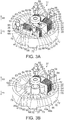
Fig. 3A is a perspective view illustrating a part of the electric motor andFig. 3B is a perspective view illustrating a part ofFig. 3A . -
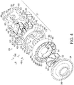
Fig. 4 is an exploded perspective view illustrating the electric blower when viewed from a fan. -
Fig. 5 is an exploded perspective view illustrating the electric blower when viewed from the electric motor. -
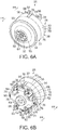
Fig. 6A is a perspective view illustrating the electric blower when viewed from the fan andFig. 6B is a perspective view illustrating the electric blower when viewed from the electric motor. -
Fig. 7 is a perspective view illustrating a vacuum cleaner including the electric blower. - Hereinafter, a configuration of an embodiment will be described with reference to
Figs. 1 to 7 . - In
Fig. 7 ,Reference Sign 11 indicates a vacuum cleaner and thevacuum cleaner 11 constitutes a vacuum cleaning machine together with a support device (which is a charging stand and is not illustrated in the drawings) which supports thevacuum cleaner 11 in an accommodation state when the vacuum cleaner is not used for a cleaning operation. - Then, in the embodiment, the
vacuum cleaner 11 is a so-called stick type vacuum cleaner which includes acleaner body 12, anair duct 15 including anextension pipe 13 serving as an elongated pipe part directly connected to thecleaner body 12 and afloor brush 14 serving as a suction port suctioning dust on a cleaning object face. - The
cleaner body 12 includes, for example, amain body 21 and adust collection device 22 which serves as a dust collection part removably attached to themain body 21. Themain body 21 includes therein anelectric blower 25, acontroller 27 which is, for example, a microcomputer controlling an operation of theelectric blower 25, and abattery 28 which is a power source. For example, thedust collection device 22 is a device to separate dust which is suctioned along with air by the operation of theelectric blower 25 and to trap the dust. Thedust collection device 22 can arbitrarily employ, for example, a type using a filter or a type of straight separation. However, in the embodiment, for example, a dust collection cup of cylindrical shape which separates dust in a centrifugal manner (a cyclone separation manner) is used. - Then, as illustrated in
Figs. 4 to 6A , theelectric blower 25 is integrally provided with anelectric motor 31, acentrifugal fan 32 which is a fan rotated by theelectric motor 31, adiffuser 33 which is a straightening member (flow control member) interposed between theelectric motor 31 and thecentrifugal fan 32, and afan cover 34 which covers thecentrifugal fan 32. - The
electric motor 31 is, for example, a brushless motor and includes astator 36, arotor 37 which is rotated by thestator 36, and a substantiallycylindrical frame 38 which accommodates thestator 36 and therotor 37 as illustrated inFig. 1 . Then, an operation of theelectric motor 31 is controlled by a control circuit (not illustrated). Hereinafter, a description will be made on the assumption that the vertical direction and the lateral direction illustrated inFig. 1 are set as the vertical direction (indicated by the arrow U and the arrow D) and the lateral direction (indicated by the arrow L and the arrow R) of the electric blower 25 (the electric motor 31), the side of theelectric motor 31 in the axial direction of theelectric blower 25 is set as the rear direction (indicated by the arrow RR inFig. 4 and the like), and the side of thecentrifugal fan 32 is set as the front direction (indicated by the arrow FR inFig. 4 and the like). - The
stator 36 is used to form a magnetic pole (a fixed magnetic pole) rotating therotor 37 and includes a plurality of, for example, a pair ofstator cores coil portions stator cores spacers stator cores stator 36 has a configuration in which thestator cores 41 are disposed radially in the radial direction of theframe 38 within theframe 38 and thestator cores - Each of one and the
other stator cores 41 is formed of a magnetic body such as an electromagnetic steel plate and is formed in a substantially C-shape by a pair ofcore portions core portions - The
core portions rotor 37. The other ends of thecore portions 45 are respectively provided withcore tooth portions 48 protruding to face therotor 37. Thecore tooth portions 48 protrude toward therotor 37 and are separated from each other in the horizontal direction. Further, as illustrated inFig. 2 , eachcore tooth portion 48 includes amagnetic action face 48a (magnetic pole face) which faces an outer peripheral face of therotor 37 and apressing object face 48b which is a portion to be pressed continuous to themagnetic action face 48a and anouter face 45a of thecore portion 45. Then, a gap between thecore tooth portions stator core 41 and a gap between thecore tooth portions stator cores slot openings 49. - A magnetic pole is formed at the
core tooth portion 48 by thecoil portion 42. Themagnetic action face 48a is used to apply the magnetic pole to therotor 37 and is curved in a circular-arc shape along the outer peripheral face of therotor 37. Themagnetic action face 48a is separated from the outer peripheral face of therotor 37 with a slight gap interposed therebetween. - The
pressing object face 48b is a portion which contacts thespacer 43 and is pressed by thespacer 43 and has a slope which is inclined to be separated from a virtual line formed in the horizontal direction passing through the center axis of the rotor 37 (the frame 38) as it goes away from the rotor 37 (themagnetic action face 48a). That is, the slope is inclined toward the outside. - The connection portion 46 illustrated in
Fig. 1 is disposed in the horizontal direction, that is, a direction substantially orthogonal to thecore portions frame 38, thestators 36 are supported by theframe 38 so as not to be rotatable in the circumferential direction. - Thus, both ends of the
stator core 41 facing theframe 38 are provided withcorner portions spacers stator core 41 from the opposite ends (thecore tooth portions - Each of the
coil portions 42 illustrated inFig. 1 andFigs. 3A and 3B includes aninsulation body 51 which is attached to thestator core 41 and acoil 52 which is wound on theinsulation body 51. - The
insulation body 51 is integrally provided with a rectangular cylindricalinsulation body part 54 through which eachcore portion 45 of thestator core 41 is inserted, an insulationbody connection portion 55 which is connected to theinsulation body part 54, andterminal portions body connection portion 55. Then, theinsulation body 51 is integrally fixed to thestator core 41, for example, by insert-molding. - The
insulation body part 54 is formed in a bobbin shape and is attached to cover an entire position of the connection portion 46 side in relation to thecore tooth portion 48 of eachcore portion 45 of thestator core 41. - The insulation
body connection portion 55 is disposed along the connection portion 46 of thestator core 41, that is, along the horizontal direction. - The
terminal portions body connection portion 55, which is the opposite side of thecentrifugal fan 32, and stack on both left and right ends of the connection portion 46 of thestator core 41. Theterminals terminal portions terminals terminal portions coils insulation body parts - The
coil 52 is formed by covering a surface of a conductor by an insulation coating and is multiply wound on eachinsulation body part 54 of theinsulation body 51. - The
spacers 43 illustrated inFig. 1 press thestator cores stator 36 against theframe 38 to be positioned and is formed of, for example, a non-magnetic material such as PBT (polybutylene terephthalate) which is softer than theframe 38. Thesespacers stator cores frame 38 so that onespacer 43 presses the left side of thestator cores other spacer 43 presses the right side of thestator cores spacer 43 presses one (the other)stator core 41 against theframe 38, the other (one)stator core 41 is pressed against theframe 38 by a reaction force transmitted from theframe 38 through thestator core 41. - Specifically, as illustrated in
Figs. 2 ,4 , and5 , each of thespacers 43 is integrally provided with acore contact portion 61 which contacts the stator core 41 (the core tooth portion 48 (thepressing object face 48b)), an insulationbody contact portion 62 which contacts theinsulation body 51, andcore regulation portions stator cores electric blower 25. Thus, thespacers stator cores insulation bodies coil portions spacers stator cores insulation bodies coil portions accommodation part 64 is formed in a recessed shape in each of thespacers 43 and a position detector (a rotation position detection sensor) 65 which detects the rotation position of therotor 37 is accommodated in theaccommodation part 64. - As illustrated in
Fig. 2 , thecore contact portion 61 is located to be continuous between thecore tooth portions 48 and 48 (the pressing object faces 48b and 48b) of thestator cores core contact portion 61 is provided with contact faces 61a and 61a which are provided at the upper and lower side portions, and are used as contact portions contacting the pressing object faces 48b and 48b of thecore tooth portions stator cores rotor 37. Here, a direction of a force of press-inserting eachspacer 43 between thecore tooth portions stator cores rotor 37 is changed so that a force of pressing thestator cores frame 38 in the radial direction is generated. Thus, thecore contact portion 61 is formed to have a trapezoidal cross-section of which a width is gradually narrowed toward therotor 37. - The insulation
body contact portion 62 is located to be continuous between theinsulation body parts insulation bodies body contact portion 62 includes contact faces 62a and 62a which are provided at the upper and lower side portions and contact theinsulation bodies frame 38. - The
core regulation portions core contact portion 61 in the longitudinal direction (Figs. 4 and5 ). Then, thecore regulation portions core tooth portions stator cores spacer 43 is press-inserted between thestator cores spacer 43 is press-inserted between thestator cores stator cores - The
accommodation part 64 is formed at a position near therotor 37 at the rear portion of thecore contact portion 61 to be recessed in the axial direction (the longitudinal direction) of therotor 37. - The
position detector 65 is used to detect a rotation position (a rotation angle) of therotor 37 by detecting the polarity of the magnetic pole of therotor 37. Here, the position detector is, for example, a hall IC and is, in the embodiment, a lead component. When the position detection unit is inserted into theaccommodation part 64, the lead portion is drawn to the outside of theaccommodation part 64. Thus, theseposition detectors slot openings lower stator cores 41 and 41 (thecore tooth portions 48 and 48) and face the outer peripheral face of the rotor at a near position separated from the outer peripheral face of therotor 37. That is, theseposition detectors rotor 37 interposed therebetween. - As illustrated in
Fig. 3B , therotor 37 includes arotation shaft 67 which is an output shaft connected to the centrifugal fan 32 (Fig. 4 ) and amagnet portion 68 which is a rotor body integrally formed with the periphery of therotation shaft 67. Then, therotor 37 is held by theframe 38 to be rotatable throughbearings - The
rotation shaft 67 is located along the center axis of theframe 38. Therotation shaft 67 is formed such that a front end side protrudes forward with respect to theframe 38 and the centrifugal fan 32 (Fig. 4 ) is connected to the protruding front end side. - A permanent magnet (not illustrated) is buried in the
magnet portion 68 and magnetic poles (rotary magnetic poles) having different polarities are formed to be adjacent to each other in the rotation direction (the circumferential direction). Thus, N and S poles are sequentially and alternately arranged in the rotation direction of themagnet portion 68 so that N and S poles make a pair. - The
bearing 69 is attached to the front end side of therotation shaft 67 and thebearing 70 is attached to the rear end of therotation shaft 67. Thesebearings frame 38 so that therotor 37 is rotatably held by theframe 38. - The
frame 38 illustrated inFigs. 1 to 5 is formed of, for example, light metal such as aluminum or magnesium or synthetic resin such as BMC (FRP). As schematically illustrated inFigs. 4 and5 , theframe 38 includes an annularouter frame portion 72, one and the other bearingportions 73 and 74 (shaft receiving portions) which support thebearings rotor 37, and one and the otherbearing connection portions outer frame portion 72 to one and the other bearingportions frame 38 is divided into a plurality of frame bodies, in the embodiment, for example, oneframe body 78 integrally provided with theouter frame portion 72, one bearingportion 73, and onebearing connection portion 75 and theother frame body 79 integrally provided with the other bearingportion 74 and the otherbearing connection portion 76 in the longitudinal direction. Oneframe body 78 and theother frame body 79 are fixed to each other in the longitudinal direction by a plurality of fixedmembers 80, for example, by screws, so that thestator 36 and therotor 37 are accommodated while being interposed therebetween in the longitudinal direction. - The
outer frame portion 72 is a portion in which thestator cores stator 36 are pressed against the inner periphery by thespacers Figs. 1 and5 , the inner periphery of theouter frame portion 72 is provided with aregulation portion 82 which protrudes and regulates the positions of thestator cores spacers regulation portion 82 regulates thestator cores rotor 37. Further, theouter frame portion 72 is provided with a plurality of screw holes 83 serving as fixed holes into which the fixedmembers 80 are threaded. For example, the screw holes are formed at four positions by penetrating in the longitudinal direction. - The
regulation portion 82 is formed at the inner periphery of theouter frame portion 72 to protrude along the axial direction of the outer frame portion 72 (the axial direction of the electric blower 25 (the electric motor 31)). In the embodiment, theregulation portion 82 is disposed at the end near theouter frame portion 72 of onebearing connection portion 75. Theseregulation portions 82 are provided to hold both corner portions facing the frame 38 (the outer frame portion 72) of thestator core 41, that is, thecorner portions core portions regulation receiving portions 82a into which thesecorner portions regulation portions 82 are provided at thestator cores 41. Thus, since theregulation portions 82 interpose thestator core 41 in the lateral direction (right and left direction) to regulate a movement in the lateral direction, thestator core 41 is positioned to theframe 38 in the lateral direction. Further, theregulation portion 82 is provided with asupport portion 82b (Fig. 5 ) to protrude in theregulation receiving portion 82a for supporting the rear sides of thecorner portions stator core 41. For this reason, since theregulation portion 82 regulates a backward movement of thestator core 41, thestator core 41 is positioned to theframe 38 in the rear direction. - As illustrated in
Fig. 5 , one and the other bearingportions bearings portions outer frame portion 72. - As illustrated in
Figs. 4 and5 , one and the otherbearing connection portions portions outer frame portion 72. Onebearing connection portion 75 is provided at a plurality of positions, for example, six positions in the lateral direction and the oblique vertical direction so that the bearing connection portions are separated from each other in the circumferential direction. Among onebearing connection portions 75, for example, onebearing connection portions 75 located at the left and right sides are provided with screw holes 86 and 86 serving as fixed hole portions into which a fixedbody 85 such as a screw fixing thediffuser 33 and theelectric motor 31 in the longitudinal direction is fixed. Then, a gap among onebearing connection portions 75 is formed as a plurality of, for example, sixventilation ports 87 through which air passing through thediffuser 33 flows into theelectric motor 31. Further, the otherbearing connection portions 76 are provided at a plurality of positions, for example, four positions in the vertical and horizontal directions to have a cross shape and are separated from each other in the circumferential direction. The front ends of the otherbearing connection portions 76 are provided withinsertion holes 88 through which a fixedmember 80 is inserted in the longitudinal direction (Fig. 4 ). As illustrated inFig. 6B , a gap among the otherbearing connection portions 76 is formed as a plurality of, for example, fourexhaust ports 89 through which air flowing into theelectric motor 31 is discharged to the outside. The terminal portions 56 (the terminal 58) and the coil portions 42 (the coil 52) of thestator 36 are respectively disposed at theexhaust ports 89 to be exposed therefrom. - The control circuit includes, for example, a driver which includes an inverter circuit and a control section which controls the driver according to PWM and the control circuit is electrically connected to the
terminal portion 56 and theposition detector 65. The control circuit switches a magnetic pole (a magnetic field direction) generated at each of thecore tooth portions stator cores 41 of thestator 36 through thecoil portion 42 illustrated inFig. 1 at every period of time by controlling a current supply time and/or a current direction of a current flowing in thecoil 52 by the driver. - The
centrifugal fan 32 illustrated inFigs. 4 and5 is rotated by theelectric motor 31 to straighten (guide) air from the center toward the outer periphery. Thecentrifugal fan 32 is formed of, for example, light metal such as aluminum or synthetic resin having excellent thermal resistance and wear resistance. Further, thecentrifugal fan 32 is integrally provided with afan body 91 which is integrally fixed to the end of the rotation shaft 67 (Fig. 6A ) of theelectric motor 31 and a plurality offan blades 92 which protrude toward a front side corresponding to an opposite side to the electric motor 31 (the diffuser 33) in thefan body 91. Thefan body 91 is formed in a cylindrical shape which gradually increases in diameter from one end (the front end) toward the other end (the rear end). Thefan blade 92 is formed in a spiral shape which is gradually bent from the center of thefan body 91 toward the outer periphery and the fan blades are separated from each other in the circumferential direction so that air is straightened from the center toward the outer periphery by the rotation of thecentrifugal fan 32 in one direction. - The
diffuser 33 is used to straighten (guide) air straightened by thecentrifugal fan 32 so that the air flows into theelectric motor 31. Thediffuser 33 includes an annularouter frame portion 93 which has substantially the same radial dimension as that of theouter frame portion 72 of theframe 38, abody portion 94 which is located at the inside of theouter frame portion 93, and a plurality ofblades 95 which connect theouter frame portion 93 and thebody portion 94 to each other. And a gap between theblades 95 is formed as anair duct 96 penetrating thediffuser 33 in the longitudinal direction. Then, thebody portion 94 is provided with, for example, a circular attachment opening 97 to which onebearing portion 73 of theelectric motor 31 is fitted so that the rotation shaft 67 (Fig. 1 ) is exposed, and with passage holes 98 and 98 which serve as fixed hole portions fixing thediffuser 33 to theelectric motor 31 by the fixed body 85 (Fig. 4 ). - The
fan cover 34 is attached to thediffuser 33 to cover a part of thecentrifugal fan 32. Thefan cover 34 is formed in a substantially cylindrical shape having substantially the same radial dimension as that of the frame 38 (the outer frame portion 72) of thediffuser 33 and theelectric motor 31. Then, thefan cover 34 is provided with an intake port 99 (suction port) which exposes the center portion of thecentrifugal fan 32 and thefan cover 34 is inclined to be gradually opened from theintake port 99. - Next, an assembly procedure of the
electric blower 25 of the embodiment will be described with reference toFigs. 1 to 6 . - First, the
electric motor 31 is assembled. That is, theinsulation body 51 is integrally molded with the preliminarily moldedstator core 41 by insert-molding. Then, thecoils insulation body parts insulation body 51, the ends of thecoils terminal portions terminals terminal portions terminals terminal portions coils coil portion 42 is formed (seeFigs. 3A and 3B ). - Next, the
magnet portion 68 and thebearings rotation shaft 67 to form therotor 37 and the bearing 69 of therotor 37 is held by one bearingportion 73 while therotation shaft 67 is inserted through one bearingportion 73 of oneframe body 78 of the preliminarily moldedframe 38. - Additionally, the
corner portions stator cores 41 provided with thecoil portion 42 are pressed between the left andright regulation portions frame body 78 while being fitted to theregulation receiving portions support portions spacers stator cores Figs. 4 and5 ). At this time, thespacers stator cores spacers stator cores spacers 43 press the pressing object faces 48b and 48b of thecore tooth portions stator cores rotor 37 so that a direction of a pressing force caused by the inclination of these contact faces 61a and 61a and the pressing object faces 48b and 48b is changed into a pressing force in which thestator cores outer frame portion 72 of the frame 38 (seeFigs. 1 and2 ). At this time, since the movement of thestator cores outer frame portion 72 of theframe 38 is regulated by theregulation portions stator cores outer frame portion 72 of theframe 38 in a pressing state and also thestator cores core regulation portions stator cores frame 38. As a result, thecontact face 61a of eachspacer 43 is pressed against the pressing object faces 48b and 48b of thestator cores insulation bodies core regulation portion 63 is pressed against the front and rear faces of thestator cores stator 36 is positioned to theframe 38 and the magnetic action faces 48a, 48a, 48a, and 48a of thecore tooth portions stator cores magnet portion 68 of therotor 37 to face each other with a predetermined gap interposed therebetween. - Further, the
position detectors 65 are respectively inserted into theaccommodation parts 64 of thespacers 43 so that theseposition detectors 65 are attached to a predetermined position which is adjacent to the outer peripheral face of themagnet portion 68 of therotor 37. - Then, one
frame body 78 to which thestator 36 and therotor 37 are assembled is covered by the preliminarily moldedother frame body 79 while eachinsertion hole 88 is positioned to eachscrew hole 83 so that thebearing 70 is held by the other bearingportion 74 and the fixedmember 80 inserted through eachinsertion hole 88 is fastened into eachscrew hole 83. Accordingly, one and theother frame bodies stator 36 and therotor 37 are interposed therebetween (seeFigs. 4 and5 ). In this state, each terminal portion 56 (the terminal 58) and each coil portion 42 (the coil 52) are exposed from each exhaust port 89 (seeFigs. 6A and 6B ). - Next, one bearing
portion 73 of theelectric motor 31 assembled in this way is fitted into the attachment opening 97 of thediffuser 33 and the fixedbody 85 is inserted through the passage holes 98 and 98 to be threaded into the screw holes 86 and 86 of theelectric motor 31. Accordingly, theelectric motor 31 and thediffuser 33 are fixed. Then, thecentrifugal fan 32 is attached to therotation shaft 67 of theelectric motor 31 protruding from the attachment opening 97 of thediffuser 33 and thefan cover 34 is press-inserted or adhered to thediffuser 33 to cover thecentrifugal fan 32. Accordingly, theelectric blower 25 is obtained (seeFigs. 4 and5 ). - In the
electric blower 25 assembled in this way, the rotation position of therotor 37 is detected by theposition detectors coil 52 of eachcoil portion 42 are controlled by the control circuit in response to the rotation position. Accordingly, magnetic poles are sequentially formed at thecore tooth portion 48 and these magnetic poles push (repulsion) or pull (attracting) the magnetic pole of therotor 37, thereby rotating therotor 37. As a result, thecentrifugal fan 32 connected to therotor 37 rotates at a high speed (for example, about 100000 rpm). Here, the vacuum cleaner 11 (Fig. 7 ) in which theelectric blower 25 is assembled to themain body 21 suctions dust of a cleaning object face together with air through thefloor brush 14 by a negative pressure generated by the rotation of thecentrifugal fan 32 of theelectric blower 25 and traps the dust by thedust collection device 22. The air having dust passes through thedust collection device 22 and is suctioned from theintake port 99 illustrated inFigs. 4 ,5 , and6A into theelectric blower 25. Then, the suctioned air is straightened to the periphery of thecentrifugal fan 32 by thecentrifugal fan 32, and is straightened by thediffuser 33 illustrated inFig. 4 so that the air flows from theair duct 96 into theelectric motor 31 through theventilation port 87. Then, the air passes through theframe 38 of theelectric motor 31 while cooling the electric motor 31 (thestator 36 and the rotor 37), and is discharged from theexhaust port 89 illustrated inFig. 6(b) while cooling each coil portion 42 (the coil 52) and each terminal portion 56 (the terminal 58). Next, the air is discharged from an exhaust hole (not illustrated) opened in themain body 21 to the outside of themain body 21. - According to the above-described embodiment, the
stator cores frame 38 by thespacers stator cores frame 38 is provided with theregulation portions stator cores spacers rotor 37. Accordingly, it is possible to easily position the plurality ofstator cores 41 to theframe 38 while ensuring reliability. - According to the embodiment, since a thermal load or a mechanical load is not applied to the
coil 52 as in, for example, a configuration in which the bridge portion is integrally molded between thestator cores stator cores 41 to theframe 38 while ensuring reliability. - Then, since the
stator cores frame 38, the assembly can be performed even when a distance between thecore tooth portions stator cores bearings - Further, since the
spacers stator cores insulation bodies coil portions stator cores spacers 43 even when the areas of the ends of theinsulation bodies stator cores - Additionally, since the
position detector 65 is accommodated in theaccommodation part 64 provided in eachspacer 43, theposition detector 65 can be disposed at a position closer to themagnet portion 68 of therotor 37. Accordingly, it is possible to improve the detection accuracy of the rotation position of therotor 37 and to control the rotation with high accuracy. - Further, since each
spacer 43 is formed of a non-magnetic body, a magnetic path of thestator 36 is not influenced and a bad effect such as degradation in output does not occur. - Additionally, since the
electric blower 25 is used for thevacuum cleaner 11, the rotation speed is high and a vibration is easily generated. For this reason, since eachspacer 43 is formed of a material softer than theframe 38, a vibration can be absorbed by eachspacer 43 and thus noise or rattling caused by a vibration can be prevented. - Additionally, two (one pair)
stator cores 41 are provided in the above-described embodiment, but three or more stator cores may be used. - Further, the
spacers 43 can be a structure filled between thestator cores insulation bodies core tooth portions stator cores insulation body parts insulation bodies - Additionally, each
spacer 43 may be formed of a conductor as long as the spacer is insulated from thestator cores - Then, the
vacuum cleaner 11 is not limited to a stick type. For example, a canister type in which an air duct including a hose body is connected to thecleaner body 12 traveling on a cleaning object face or a robot type in which a cleaning object face is cleaned while the cleaner body autonomously travels thereon can be employed. - When an embodiment of the invention has been described, the embodiment is merely an example and does not limit the scope of the invention. The novel embodiment can be modified into various forms and various omissions, substitutions, and modifications thereof can be made without departing from the spirit of the invention. The embodiment or the modification thereof is included in the scope or the spirit of the invention and is included in the invention of claims and the equivalent range thereof.
- While certain embodiments have been described, these embodiments have been presented by way of example only, and are not intended to limit the scope of the inventions. Indeed, the novel embodiments described herein may be embodied in a variety of other forms; furthermore, various omissions substitutions and changes in the form of the embodiments described herein may be made without departing from the spirit of the inventions. The accompanying claims and their equivalents are intended to cover such forms or modifications as would fall within the scope and spirit of the inventions.
-
- 11
- vacuum cleaner
- 22
- dust collection part (dust collection device)
- 25
- electric blower
- 31
- electric motor
- 32
- fan (centrifugal fan)
- 36
- stator
- 37
- rotor
- 38
- frame
- 41
- stator core
- 42
- coil portion
- 43
- spacer
- 48
- core tooth portion
- 51
- insulation body
- 52
- coil
- 64
- accommodation part
- 65
- position detector
- 82
- regulation portion
Claims (14)
- An electric blower comprising:an electric motor; anda fan rotated by the electric motor,
whereinthe electric motor includes a stator, a rotor connected to the fan, and a frame accommodating the stator and the rotor,the stator includes a plurality of stator cores respectively having a core tooth portion facing the rotor, a coil portion attached to the stator core to form a magnetic pole at the core tooth portion, and a spacer inserted between the stator cores to press the stator cores against the frame, andthe frame includes a regulation portion regulating position of the stator core pressed by the spacer. - The electric blower according to claim 1,
wherein the spacer is disposed to be filled between the stator cores. - The electric blower according to claim 1 or 2,
wherein the coil portion includes a coil formed by a conductor and an insulation body attached to the stator core to insulate the stator core and the coil, and
the spacer is disposed to be filled between the insulation bodies of the coil portions. - The electric blower according to any one of claims 1 to 3,
wherein the coil portion includes a coil formed by a conductor and an insulation body attached to the stator core to insulate the stator core and the coil, and
the spacer is disposed to be filled between the stator cores and between the insulation bodies of the coil portions. - The electric blower according to any one of claims 1 to 4,
wherein a contact face of the spacer and a face to be pressed of the stator core are inclined. - The electric blower according to any one of claims 1 to 5,
wherein spacers are respectively inserted from both sides of the stator cores. - The electric blower according to any one of claims 1 to 6,
wherein the regulation portion of the frame regulates the position of the stator core in a rotation direction of the rotor. - The electric blower according to any one of claims 1 to 7,
wherein the stator core is regulated in a longitudinal direction by the regulation portion. - The electric blower according to any one of claims 1 to 8,
a plurality of regulation portions are arranged in the frame. - The electric blower according to any one of claims 1 to 9,
wherein the stator core is formed in a C-shape. - The electric blower according to any one of claims 1 to 10, further comprising:a position detector detecting a rotation position of the rotor,wherein the spacer includes an accommodation part located between the stator cores, and at least a part of the position detector is accommodated therein.
- The electric blower according to any one of claims 1 to 11,
wherein the spacer is formed of a non-magnetic body. - The electric blower according to any one of claims 1 to 12,
wherein the spacer is formed of a material softer than the frame. - A vacuum cleaner comprising:the electric blower according to any one of claims 1 to 13; anda dust collection part trapping dust suctioned together with air by an operation of the electric blower.
Applications Claiming Priority (1)
| Application Number | Priority Date | Filing Date | Title |
|---|---|---|---|
| JP2016028187A JP6599791B2 (en) | 2016-02-17 | 2016-02-17 | Electric blower and vacuum cleaner |
Publications (2)
| Publication Number | Publication Date |
|---|---|
| EP3208914A1 true EP3208914A1 (en) | 2017-08-23 |
| EP3208914B1 EP3208914B1 (en) | 2019-11-06 |
Family
ID=57890715
Family Applications (1)
| Application Number | Title | Priority Date | Filing Date |
|---|---|---|---|
| EP17152915.9A Active EP3208914B1 (en) | 2016-02-17 | 2017-01-24 | Electric blower using an electric motor using a plurality of stator cores and vacuum cleaner using this electric blower |
Country Status (4)
| Country | Link |
|---|---|
| US (1) | US10426309B2 (en) |
| EP (1) | EP3208914B1 (en) |
| JP (1) | JP6599791B2 (en) |
| CN (1) | CN107093930B (en) |
Cited By (1)
| Publication number | Priority date | Publication date | Assignee | Title |
|---|---|---|---|---|
| WO2020065254A1 (en) * | 2018-09-28 | 2020-04-02 | Dyson Technology Limited | A stator core assembly |
Families Citing this family (12)
| Publication number | Priority date | Publication date | Assignee | Title |
|---|---|---|---|---|
| GB2563614B (en) * | 2017-06-20 | 2020-06-17 | Dyson Technology Ltd | Brushless motor |
| GB2563613B (en) * | 2017-06-20 | 2021-10-20 | Dyson Technology Ltd | A brushless motor and stator therefor |
| JP6948274B2 (en) * | 2018-02-15 | 2021-10-13 | 東芝ライフスタイル株式会社 | Electric blower and vacuum cleaner |
| CN110768474B (en) * | 2018-07-27 | 2025-07-25 | 广东威灵电机制造有限公司 | Motor and washing machine with same |
| CN109185196B (en) * | 2018-09-30 | 2020-04-10 | 广东威灵电机制造有限公司 | Electric fan |
| JP2020112061A (en) * | 2019-01-09 | 2020-07-27 | 日本電産株式会社 | Blower and cleaner |
| CN110575098B (en) * | 2019-09-29 | 2024-08-27 | 苏州市春菊电器有限公司 | Dust cup structure of dust collector and dust collector |
| CN112806901A (en) * | 2019-11-18 | 2021-05-18 | 珠海格力电器股份有限公司 | Motor and dust catcher |
| KR102797009B1 (en) * | 2020-05-08 | 2025-04-18 | 엘지전자 주식회사 | Motor assembly |
| KR102814546B1 (en) * | 2020-05-08 | 2025-05-29 | 엘지전자 주식회사 | Motor assembly |
| KR20230101428A (en) * | 2021-12-29 | 2023-07-06 | 삼성전자주식회사 | Motor assembly for cleaner |
| WO2025197079A1 (en) * | 2024-03-22 | 2025-09-25 | 本田技研工業株式会社 | Stator and stator fixing structure |
Citations (4)
| Publication number | Priority date | Publication date | Assignee | Title |
|---|---|---|---|---|
| EP1835595A2 (en) * | 2006-03-16 | 2007-09-19 | Motec Components GmbH & Co. KG | One-phase switched reluctance motor |
| DE102011052131A1 (en) * | 2011-07-26 | 2013-01-31 | actiro Power Blower GmbH | Reluctance motor i.e. single-phase switched reluctance motor, has compensation elements that are opposite to each other for limiting displacement of iron core, where compensation elements are firmly bonded |
| US20130249330A1 (en) * | 2012-03-23 | 2013-09-26 | Dyson Technology Limited | Stator for an electrical machine |
| EP2961038A1 (en) * | 2014-06-05 | 2015-12-30 | Samsung Electronics Co., Ltd. | Vacuum cleaner with motor assembly |
Family Cites Families (6)
| Publication number | Priority date | Publication date | Assignee | Title |
|---|---|---|---|---|
| US3041487A (en) * | 1957-12-10 | 1962-06-26 | Hurst Tool & Mfg Co Inc | Shading coil and pole piece for synchronous motor |
| JPS5363602U (en) * | 1976-10-25 | 1978-05-29 | ||
| US4134036A (en) * | 1977-06-03 | 1979-01-09 | Cooper Industries, Inc. | Motor mounting device |
| JPS58380Y2 (en) * | 1978-03-22 | 1983-01-06 | ジエコ−株式会社 | Synchronous motor stator assembly structure |
| DE102010034890A1 (en) * | 2009-08-21 | 2011-03-10 | Johnson Electric S.A. | Universal motor |
| GB2513665B (en) * | 2013-05-03 | 2016-01-06 | Dyson Technology Ltd | Compressor |
-
2016
- 2016-02-17 JP JP2016028187A patent/JP6599791B2/en active Active
-
2017
- 2017-01-16 CN CN201710032179.2A patent/CN107093930B/en active Active
- 2017-01-24 EP EP17152915.9A patent/EP3208914B1/en active Active
- 2017-01-26 US US15/416,088 patent/US10426309B2/en not_active Expired - Fee Related
Patent Citations (4)
| Publication number | Priority date | Publication date | Assignee | Title |
|---|---|---|---|---|
| EP1835595A2 (en) * | 2006-03-16 | 2007-09-19 | Motec Components GmbH & Co. KG | One-phase switched reluctance motor |
| DE102011052131A1 (en) * | 2011-07-26 | 2013-01-31 | actiro Power Blower GmbH | Reluctance motor i.e. single-phase switched reluctance motor, has compensation elements that are opposite to each other for limiting displacement of iron core, where compensation elements are firmly bonded |
| US20130249330A1 (en) * | 2012-03-23 | 2013-09-26 | Dyson Technology Limited | Stator for an electrical machine |
| EP2961038A1 (en) * | 2014-06-05 | 2015-12-30 | Samsung Electronics Co., Ltd. | Vacuum cleaner with motor assembly |
Cited By (4)
| Publication number | Priority date | Publication date | Assignee | Title |
|---|---|---|---|---|
| WO2020065254A1 (en) * | 2018-09-28 | 2020-04-02 | Dyson Technology Limited | A stator core assembly |
| CN112771757A (en) * | 2018-09-28 | 2021-05-07 | 戴森技术有限公司 | Stator core assembly |
| GB2577546B (en) * | 2018-09-28 | 2023-05-24 | Dyson Technology Ltd | A stator core assembly |
| CN112771757B (en) * | 2018-09-28 | 2024-06-11 | 戴森技术有限公司 | Stator core assembly |
Also Published As
| Publication number | Publication date |
|---|---|
| CN107093930A (en) | 2017-08-25 |
| JP2017147863A (en) | 2017-08-24 |
| US10426309B2 (en) | 2019-10-01 |
| US20170231451A1 (en) | 2017-08-17 |
| JP6599791B2 (en) | 2019-10-30 |
| EP3208914B1 (en) | 2019-11-06 |
| CN107093930B (en) | 2019-08-27 |
Similar Documents
| Publication | Publication Date | Title |
|---|---|---|
| US10426309B2 (en) | Electric blower and vacuum cleaner | |
| US9653960B2 (en) | Motor and blower | |
| JP6791692B2 (en) | Electric blower | |
| TWI586081B (en) | Brushless motor and manufacturing method thereof | |
| CN109104007B (en) | Brushless motor and stator thereof | |
| JP2018084151A (en) | Electric blower and vacuum cleaner | |
| JP7225752B2 (en) | blower and vacuum cleaner | |
| JP2005160296A (en) | Electric motor with sensor for detecting rotor position | |
| JP6796465B2 (en) | Electric blower and vacuum cleaner | |
| JP6791691B2 (en) | Electric blower | |
| JPWO2020183574A1 (en) | Motors, electric blowers, vacuum cleaners and hand dryers | |
| JP6859074B2 (en) | Electric motor and vacuum cleaner | |
| CN1783655A (en) | Electric blower and method for constructing the same | |
| JP5708432B2 (en) | Rotating electric machine and air conditioner using the same | |
| JP6948274B2 (en) | Electric blower and vacuum cleaner | |
| JP2018074860A (en) | Electric motor and vacuum cleaner | |
| JP6271267B2 (en) | Brushless motor and electric blower | |
| JP2015142499A (en) | brushless motor | |
| JPH0570183U (en) | Brushless motor for blower | |
| CN110476333A (en) | Electric blowers and electric vacuum cleaners |
Legal Events
| Date | Code | Title | Description |
|---|---|---|---|
| PUAI | Public reference made under article 153(3) epc to a published international application that has entered the european phase |
Free format text: ORIGINAL CODE: 0009012 |
|
| STAA | Information on the status of an ep patent application or granted ep patent |
Free format text: STATUS: REQUEST FOR EXAMINATION WAS MADE |
|
| 17P | Request for examination filed |
Effective date: 20170124 |
|
| AK | Designated contracting states |
Kind code of ref document: A1 Designated state(s): AL AT BE BG CH CY CZ DE DK EE ES FI FR GB GR HR HU IE IS IT LI LT LU LV MC MK MT NL NO PL PT RO RS SE SI SK SM TR |
|
| AX | Request for extension of the european patent |
Extension state: BA ME |
|
| RBV | Designated contracting states (corrected) |
Designated state(s): AL AT BE BG CH CY CZ DE DK EE ES FI FR GB GR HR HU IE IS IT LI LT LU LV MC MK MT NL NO PL PT RO RS SE SI SK SM TR |
|
| STAA | Information on the status of an ep patent application or granted ep patent |
Free format text: STATUS: EXAMINATION IS IN PROGRESS |
|
| 17Q | First examination report despatched |
Effective date: 20180816 |
|
| GRAP | Despatch of communication of intention to grant a patent |
Free format text: ORIGINAL CODE: EPIDOSNIGR1 |
|
| STAA | Information on the status of an ep patent application or granted ep patent |
Free format text: STATUS: GRANT OF PATENT IS INTENDED |
|
| INTG | Intention to grant announced |
Effective date: 20190715 |
|
| GRAS | Grant fee paid |
Free format text: ORIGINAL CODE: EPIDOSNIGR3 |
|
| GRAA | (expected) grant |
Free format text: ORIGINAL CODE: 0009210 |
|
| STAA | Information on the status of an ep patent application or granted ep patent |
Free format text: STATUS: THE PATENT HAS BEEN GRANTED |
|
| AK | Designated contracting states |
Kind code of ref document: B1 Designated state(s): AL AT BE BG CH CY CZ DE DK EE ES FI FR GB GR HR HU IE IS IT LI LT LU LV MC MK MT NL NO PL PT RO RS SE SI SK SM TR |
|
| REG | Reference to a national code |
Ref country code: GB Ref legal event code: FG4D |
|
| REG | Reference to a national code |
Ref country code: AT Ref legal event code: REF Ref document number: 1200136 Country of ref document: AT Kind code of ref document: T Effective date: 20191115 Ref country code: CH Ref legal event code: EP |
|
| REG | Reference to a national code |
Ref country code: DE Ref legal event code: R096 Ref document number: 602017008305 Country of ref document: DE |
|
| REG | Reference to a national code |
Ref country code: IE Ref legal event code: FG4D |
|
| REG | Reference to a national code |
Ref country code: NL Ref legal event code: MP Effective date: 20191106 |
|
| REG | Reference to a national code |
Ref country code: LT Ref legal event code: MG4D |
|
| PG25 | Lapsed in a contracting state [announced via postgrant information from national office to epo] |
Ref country code: FI Free format text: LAPSE BECAUSE OF FAILURE TO SUBMIT A TRANSLATION OF THE DESCRIPTION OR TO PAY THE FEE WITHIN THE PRESCRIBED TIME-LIMIT Effective date: 20191106 Ref country code: BG Free format text: LAPSE BECAUSE OF FAILURE TO SUBMIT A TRANSLATION OF THE DESCRIPTION OR TO PAY THE FEE WITHIN THE PRESCRIBED TIME-LIMIT Effective date: 20200206 Ref country code: LT Free format text: LAPSE BECAUSE OF FAILURE TO SUBMIT A TRANSLATION OF THE DESCRIPTION OR TO PAY THE FEE WITHIN THE PRESCRIBED TIME-LIMIT Effective date: 20191106 Ref country code: GR Free format text: LAPSE BECAUSE OF FAILURE TO SUBMIT A TRANSLATION OF THE DESCRIPTION OR TO PAY THE FEE WITHIN THE PRESCRIBED TIME-LIMIT Effective date: 20200207 Ref country code: NO Free format text: LAPSE BECAUSE OF FAILURE TO SUBMIT A TRANSLATION OF THE DESCRIPTION OR TO PAY THE FEE WITHIN THE PRESCRIBED TIME-LIMIT Effective date: 20200206 Ref country code: PT Free format text: LAPSE BECAUSE OF FAILURE TO SUBMIT A TRANSLATION OF THE DESCRIPTION OR TO PAY THE FEE WITHIN THE PRESCRIBED TIME-LIMIT Effective date: 20200306 Ref country code: PL Free format text: LAPSE BECAUSE OF FAILURE TO SUBMIT A TRANSLATION OF THE DESCRIPTION OR TO PAY THE FEE WITHIN THE PRESCRIBED TIME-LIMIT Effective date: 20191106 Ref country code: LV Free format text: LAPSE BECAUSE OF FAILURE TO SUBMIT A TRANSLATION OF THE DESCRIPTION OR TO PAY THE FEE WITHIN THE PRESCRIBED TIME-LIMIT Effective date: 20191106 Ref country code: SE Free format text: LAPSE BECAUSE OF FAILURE TO SUBMIT A TRANSLATION OF THE DESCRIPTION OR TO PAY THE FEE WITHIN THE PRESCRIBED TIME-LIMIT Effective date: 20191106 Ref country code: NL Free format text: LAPSE BECAUSE OF FAILURE TO SUBMIT A TRANSLATION OF THE DESCRIPTION OR TO PAY THE FEE WITHIN THE PRESCRIBED TIME-LIMIT Effective date: 20191106 |
|
| PG25 | Lapsed in a contracting state [announced via postgrant information from national office to epo] |
Ref country code: HR Free format text: LAPSE BECAUSE OF FAILURE TO SUBMIT A TRANSLATION OF THE DESCRIPTION OR TO PAY THE FEE WITHIN THE PRESCRIBED TIME-LIMIT Effective date: 20191106 Ref country code: IS Free format text: LAPSE BECAUSE OF FAILURE TO SUBMIT A TRANSLATION OF THE DESCRIPTION OR TO PAY THE FEE WITHIN THE PRESCRIBED TIME-LIMIT Effective date: 20200306 Ref country code: RS Free format text: LAPSE BECAUSE OF FAILURE TO SUBMIT A TRANSLATION OF THE DESCRIPTION OR TO PAY THE FEE WITHIN THE PRESCRIBED TIME-LIMIT Effective date: 20191106 |
|
| PG25 | Lapsed in a contracting state [announced via postgrant information from national office to epo] |
Ref country code: AL Free format text: LAPSE BECAUSE OF FAILURE TO SUBMIT A TRANSLATION OF THE DESCRIPTION OR TO PAY THE FEE WITHIN THE PRESCRIBED TIME-LIMIT Effective date: 20191106 |
|
| PG25 | Lapsed in a contracting state [announced via postgrant information from national office to epo] |
Ref country code: RO Free format text: LAPSE BECAUSE OF FAILURE TO SUBMIT A TRANSLATION OF THE DESCRIPTION OR TO PAY THE FEE WITHIN THE PRESCRIBED TIME-LIMIT Effective date: 20191106 Ref country code: EE Free format text: LAPSE BECAUSE OF FAILURE TO SUBMIT A TRANSLATION OF THE DESCRIPTION OR TO PAY THE FEE WITHIN THE PRESCRIBED TIME-LIMIT Effective date: 20191106 Ref country code: DK Free format text: LAPSE BECAUSE OF FAILURE TO SUBMIT A TRANSLATION OF THE DESCRIPTION OR TO PAY THE FEE WITHIN THE PRESCRIBED TIME-LIMIT Effective date: 20191106 Ref country code: CZ Free format text: LAPSE BECAUSE OF FAILURE TO SUBMIT A TRANSLATION OF THE DESCRIPTION OR TO PAY THE FEE WITHIN THE PRESCRIBED TIME-LIMIT Effective date: 20191106 |
|
| REG | Reference to a national code |
Ref country code: DE Ref legal event code: R097 Ref document number: 602017008305 Country of ref document: DE |
|
| REG | Reference to a national code |
Ref country code: AT Ref legal event code: MK05 Ref document number: 1200136 Country of ref document: AT Kind code of ref document: T Effective date: 20191106 |
|
| PG25 | Lapsed in a contracting state [announced via postgrant information from national office to epo] |
Ref country code: SM Free format text: LAPSE BECAUSE OF FAILURE TO SUBMIT A TRANSLATION OF THE DESCRIPTION OR TO PAY THE FEE WITHIN THE PRESCRIBED TIME-LIMIT Effective date: 20191106 Ref country code: SK Free format text: LAPSE BECAUSE OF FAILURE TO SUBMIT A TRANSLATION OF THE DESCRIPTION OR TO PAY THE FEE WITHIN THE PRESCRIBED TIME-LIMIT Effective date: 20191106 Ref country code: MC Free format text: LAPSE BECAUSE OF FAILURE TO SUBMIT A TRANSLATION OF THE DESCRIPTION OR TO PAY THE FEE WITHIN THE PRESCRIBED TIME-LIMIT Effective date: 20191106 |
|
| REG | Reference to a national code |
Ref country code: CH Ref legal event code: PL |
|
| PLBE | No opposition filed within time limit |
Free format text: ORIGINAL CODE: 0009261 |
|
| STAA | Information on the status of an ep patent application or granted ep patent |
Free format text: STATUS: NO OPPOSITION FILED WITHIN TIME LIMIT |
|
| 26N | No opposition filed |
Effective date: 20200807 |
|
| REG | Reference to a national code |
Ref country code: BE Ref legal event code: MM Effective date: 20200131 |
|
| PG25 | Lapsed in a contracting state [announced via postgrant information from national office to epo] |
Ref country code: LU Free format text: LAPSE BECAUSE OF NON-PAYMENT OF DUE FEES Effective date: 20200124 Ref country code: FR Free format text: LAPSE BECAUSE OF NON-PAYMENT OF DUE FEES Effective date: 20200131 Ref country code: ES Free format text: LAPSE BECAUSE OF FAILURE TO SUBMIT A TRANSLATION OF THE DESCRIPTION OR TO PAY THE FEE WITHIN THE PRESCRIBED TIME-LIMIT Effective date: 20191106 |
|
| PG25 | Lapsed in a contracting state [announced via postgrant information from national office to epo] |
Ref country code: AT Free format text: LAPSE BECAUSE OF FAILURE TO SUBMIT A TRANSLATION OF THE DESCRIPTION OR TO PAY THE FEE WITHIN THE PRESCRIBED TIME-LIMIT Effective date: 20191106 Ref country code: BE Free format text: LAPSE BECAUSE OF NON-PAYMENT OF DUE FEES Effective date: 20200131 Ref country code: LI Free format text: LAPSE BECAUSE OF NON-PAYMENT OF DUE FEES Effective date: 20200131 Ref country code: CH Free format text: LAPSE BECAUSE OF NON-PAYMENT OF DUE FEES Effective date: 20200131 Ref country code: SI Free format text: LAPSE BECAUSE OF FAILURE TO SUBMIT A TRANSLATION OF THE DESCRIPTION OR TO PAY THE FEE WITHIN THE PRESCRIBED TIME-LIMIT Effective date: 20191106 |
|
| PG25 | Lapsed in a contracting state [announced via postgrant information from national office to epo] |
Ref country code: IE Free format text: LAPSE BECAUSE OF NON-PAYMENT OF DUE FEES Effective date: 20200124 Ref country code: IT Free format text: LAPSE BECAUSE OF FAILURE TO SUBMIT A TRANSLATION OF THE DESCRIPTION OR TO PAY THE FEE WITHIN THE PRESCRIBED TIME-LIMIT Effective date: 20191106 |
|
| PGFP | Annual fee paid to national office [announced via postgrant information from national office to epo] |
Ref country code: DE Payment date: 20210112 Year of fee payment: 5 |
|
| GBPC | Gb: european patent ceased through non-payment of renewal fee |
Effective date: 20210124 |
|
| PG25 | Lapsed in a contracting state [announced via postgrant information from national office to epo] |
Ref country code: GB Free format text: LAPSE BECAUSE OF NON-PAYMENT OF DUE FEES Effective date: 20210124 |
|
| PG25 | Lapsed in a contracting state [announced via postgrant information from national office to epo] |
Ref country code: TR Free format text: LAPSE BECAUSE OF FAILURE TO SUBMIT A TRANSLATION OF THE DESCRIPTION OR TO PAY THE FEE WITHIN THE PRESCRIBED TIME-LIMIT Effective date: 20191106 Ref country code: MT Free format text: LAPSE BECAUSE OF FAILURE TO SUBMIT A TRANSLATION OF THE DESCRIPTION OR TO PAY THE FEE WITHIN THE PRESCRIBED TIME-LIMIT Effective date: 20191106 Ref country code: CY Free format text: LAPSE BECAUSE OF FAILURE TO SUBMIT A TRANSLATION OF THE DESCRIPTION OR TO PAY THE FEE WITHIN THE PRESCRIBED TIME-LIMIT Effective date: 20191106 |
|
| PG25 | Lapsed in a contracting state [announced via postgrant information from national office to epo] |
Ref country code: MK Free format text: LAPSE BECAUSE OF FAILURE TO SUBMIT A TRANSLATION OF THE DESCRIPTION OR TO PAY THE FEE WITHIN THE PRESCRIBED TIME-LIMIT Effective date: 20191106 |
|
| REG | Reference to a national code |
Ref country code: DE Ref legal event code: R119 Ref document number: 602017008305 Country of ref document: DE |
|
| PG25 | Lapsed in a contracting state [announced via postgrant information from national office to epo] |
Ref country code: DE Free format text: LAPSE BECAUSE OF NON-PAYMENT OF DUE FEES Effective date: 20220802 |