EP3208887A1 - A multiple-input multiple-output (mimo) omnidirectional antenna - Google Patents
A multiple-input multiple-output (mimo) omnidirectional antenna Download PDFInfo
- Publication number
- EP3208887A1 EP3208887A1 EP17156780.3A EP17156780A EP3208887A1 EP 3208887 A1 EP3208887 A1 EP 3208887A1 EP 17156780 A EP17156780 A EP 17156780A EP 3208887 A1 EP3208887 A1 EP 3208887A1
- Authority
- EP
- European Patent Office
- Prior art keywords
- antenna
- columns
- input multiple
- output
- omnidirectional antenna
- Prior art date
- Legal status (The legal status is an assumption and is not a legal conclusion. Google has not performed a legal analysis and makes no representation as to the accuracy of the status listed.)
- Granted
Links
Images




Classifications
-
- H—ELECTRICITY
- H01—ELECTRIC ELEMENTS
- H01Q—ANTENNAS, i.e. RADIO AERIALS
- H01Q21/00—Antenna arrays or systems
- H01Q21/24—Combinations of antenna units polarised in different directions for transmitting or receiving circularly and elliptically polarised waves or waves linearly polarised in any direction
- H01Q21/26—Turnstile or like antennas comprising arrangements of three or more elongated elements disposed radially and symmetrically in a horizontal plane about a common centre
-
- H—ELECTRICITY
- H01—ELECTRIC ELEMENTS
- H01Q—ANTENNAS, i.e. RADIO AERIALS
- H01Q1/00—Details of, or arrangements associated with, antennas
- H01Q1/12—Supports; Mounting means
- H01Q1/22—Supports; Mounting means by structural association with other equipment or articles
- H01Q1/24—Supports; Mounting means by structural association with other equipment or articles with receiving set
- H01Q1/241—Supports; Mounting means by structural association with other equipment or articles with receiving set used in mobile communications, e.g. GSM
- H01Q1/246—Supports; Mounting means by structural association with other equipment or articles with receiving set used in mobile communications, e.g. GSM specially adapted for base stations
-
- H—ELECTRICITY
- H01—ELECTRIC ELEMENTS
- H01Q—ANTENNAS, i.e. RADIO AERIALS
- H01Q1/00—Details of, or arrangements associated with, antennas
- H01Q1/42—Housings not intimately mechanically associated with radiating elements, e.g. radome
-
- H—ELECTRICITY
- H01—ELECTRIC ELEMENTS
- H01Q—ANTENNAS, i.e. RADIO AERIALS
- H01Q21/00—Antenna arrays or systems
-
- H—ELECTRICITY
- H01—ELECTRIC ELEMENTS
- H01Q—ANTENNAS, i.e. RADIO AERIALS
- H01Q21/00—Antenna arrays or systems
- H01Q21/06—Arrays of individually energised antenna units similarly polarised and spaced apart
- H01Q21/20—Arrays of individually energised antenna units similarly polarised and spaced apart the units being spaced along or adjacent to a curvilinear path
- H01Q21/205—Arrays of individually energised antenna units similarly polarised and spaced apart the units being spaced along or adjacent to a curvilinear path providing an omnidirectional coverage
-
- H—ELECTRICITY
- H01—ELECTRIC ELEMENTS
- H01Q—ANTENNAS, i.e. RADIO AERIALS
- H01Q21/00—Antenna arrays or systems
- H01Q21/24—Combinations of antenna units polarised in different directions for transmitting or receiving circularly and elliptically polarised waves or waves linearly polarised in any direction
Definitions
- This present invention relates to a particular design of a Multiple-Input Multiple-Output (MIMO) omnidirectional antenna.
- MIMO Multiple-Input Multiple-Output
- the present invention is further directed towards a first example of such a design which realises a 4x4 MIMO omnidirectional antenna, and a second example of such a design which realises an 8x8 MIMO omnidirectional antenna.
- Alternative variants of higher order MIMO omnidirectional antennas also fit with the design of the present invention and all are considered to be within the scope of the present invention.
- MIMO systems have long been considered as an effective way to increase the data throughput along a radio frequency channel by utilising the multi-path propagation which will occur naturally in transmission environments.
- the multipath propagation allows multiple data streams to be transmitted over the same channel, by using multiple antennas on the transmitter side and multiple antennas on the receiver side.
- MIMO has become an essential part of a plurality of wireless communications standards, such as IEEE 802.11n, IEEE 802.11ac, HSPA+, WiMAX, and 4G Long Term Evolution and the emerging 5G standard.
- wireless communications standards such as IEEE 802.11n, IEEE 802.11ac, HSPA+, WiMAX, and 4G Long Term Evolution and the emerging 5G standard.
- a column set shall be understood to refer to two or more columns which act to form a section of radiation coverage over a portion of the 360° coverage area covered by the omnidirectional antenna.
- an omnidirectional antenna comprises three columns sets, then the antenna columns in each of the three column sets will act to cover approximately 120° of the 360 ° coverage area.
- the antenna columns in each of the six columns sets will act to cover substantially 60° of the 360° coverage area of the omnidirectional antenna.
- an “antenna column” shall be understood to refer to an outwardly facing component of the antenna which will mount one or more antenna radiator elements which directs the beam of radiation from the radiators.
- a radiation element an “antenna radiator”, a “radiator element”, a “radiation element”, and/or an “antenna radiation element” shall be understood to refer to the component of the antenna which transmits/radiates the antenna beam.
- 2x2 MIMO omnidirectional antennas are used to transmit approximately double the amount of data over a radio frequency channel compared to a single, typical antenna arrangement.
- the 2x2 MIMO omnidirectional antenna arrangement achieves this doubling of throughput by using two antennas, co-located on the transmitter side, and, two antennas co-located on the receiver side.
- 2x2 MIMO omnidirectional antennas are deployed in the real world at present and have achieved great commercial success.
- the 2x2 MIMO omnidirectional antenna For the 2x2 MIMO omnidirectional antenna, a three- or four-sided design may be used. The three-sided type of design is shown in Figure 1a and Figure 1b shows the type of radiation pattern which this three-sided 2x2 MIMO omnidirectional antenna produces.
- the three-sided 2x2 MIMO omnidirectional antenna comprises three antenna columns 102A, 102B, 102C which each have a plurality of radiators mounted thereto and are housed within a radome 106.
- the 2x2 MlMO omnidirectional antenna is popular for microcell deployments, where a low power base station is used to form the microcell in a mobile phone network.
- the coverage afforded by the low power base station in the microcell is determined by using power control so as to limit the range of the microcell's coverage area.
- the typical range of a microcell is a few hundred metres and is usually less than two kilometres wide, whereas standard base stations deployed on a macrocell may have ranges of up to 40 kilometres.
- the level of ripple which is defined by the range of signal loss in dB between the strongest signal 110 and the weakest signal 112, is relatively small (approx. 1.5dB) and is considered to be more than acceptable.
- the 2x2 MIMO omnidirectional antenna typically consist of +/- 45° polarisations or H&V polarisations.
- the +/-45° omnidirectional antennas are often referred to as a Pseudo Omni, or Quasi Omni, as they do not have a perfect omnidirectional pattern, which would be substantially circular in nature when viewed on a radiation polar plot.
- ripple is present on a 2x2 MIMO omnidirectional antenna pattern and this ripple causes deviation from a perfectly circular pattern.
- the amount of ripple can vary depending on which antenna manufacturer constructed the antenna and the construction techniques they used.
- 2x2 MIMO omnidirectional antennas with very good or acceptable levels of ripple are commercially deployed and popular for microcells as the antenna design allows for a relatively compact antenna to fit within a radome, which is a tubular cover for the antenna, having a relatively small diameter.
- Focus has now turned to 4x4 MIMO omnidirectional antennas in order to achieve a further approximate doubling of throughput again.
- a commercially deployed solution for providing a 4x4 MIMO omnidirectional antenna has been to provide two 2x2 MIMO omnidirectional antennas in a physically separated arrangement.
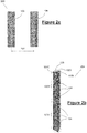
- This arrangement is shown in Figure 2a .
- the 4x4 MIMO omnidirectional antenna 200 of the prior art comprises two 2x2 MIMO omnidirectional antennas 100 as are known in the prior art and which are physically separated by a predefined distance 202.
- This predefined distance 202 is usually 10 times the wavelength ( ⁇ ) of the transmission wave.
- This arrangement is easy to deploy but is undesirable as the overall size of the arrangement is relatively large and is widely considered to be an eyesore, particularly in urban environments.
- the 4x4 MIMO omnidirectional antenna 204 of the prior art comprises two 2x2 MIMO omnidirectional antennas 100A, 100B as are known in the prior art and which are stacked within the radome 205.
- the 4x4 MIMO omnidirectional antenna 206 of the prior art comprises six antenna columns 210A, 210B, 210C, 210D, 210E, 210F with pairs of antenna columns 210A/210B, 210C/210D, 210E/210F arranged side-by-side to form a three-sided omnidirectional antenna housed within a radome 208.
- Each of the pairs of antenna columns 210A/210B, 210C/210D, 210E1210F arranged side-by-side form one of three column sets.
- the diameter of the radome 208 for the side-by-side approach is quite large and this is unwelcome.
- the side-by-side arrangement of the radiators on the antenna columns 210A-F causes a larger ripple effect of the radiation pattern which can exceed +/-5.0dB as is seen from Figure 2d .
- the radiation plot 212 in Figure 2d shows some acceptable signal strength 214 in some directions, but effectively null areas 216 in other directions. This is beyond the acceptable levels of ripple for microcell coverage and therefore, the 4x4 MIMO omnidirectional antennas 206 using the side-by-side arrangement are not foreseen to be tolerable for many real world deployments.
- PCT Patent Application Number PCT/AU2011/000365 discloses the use of phase shifting input signals through a Butler matrix to provide a 4x4 MIMO omnidirectional antenna.
- a six column antenna which is arranged in a hexagonal shape, is disclosed. This hexagonally arranged set of columns each receives each of the four input signals, which have been phase shifted prior to radiation by a plurality of dual polarised antenna elements on each column. It is well known in the art that the use of such phase shifting techniques causes excessive ripple of a radiation plot and this will affect the omnidirectional nature of the antenna coverage.
- each column receives each of the four input signals after the input signals have been passed through a pair of six-way Butler matrices.
- Such a technique will cause ripple of up to 20dB. This can be seen from the radiation plot indicated generally by reference numeral 600, shown in Figure 6 .
- the present invention is directed to a Multiple-Input Multiple-Output (MIMO) omnidirectional antenna comprising three or more column sets, where the three or more column sets are arranged in a centrosymmetric arrangement about a centre point of the antenna; each column set comprising two or more antenna columns and each of the antenna columns mounting a plurality of radiators thereon; whereby, each antenna column receives no more than two signals to be transmitted, and, each of the antenna columns is arranged to be axisymmetric about a radially-directed axis which extends between the centre point of the antenna and a transverse cross-sectional midpoint on the antenna column; such that, each radiation pattern established by each of the three or more column sets is centrosymmetric about the centre point of the antenna, and, is also axisymmetric about the radially-directed axis.
- MIMO Multiple-Input Multiple-Output
- the advantage of providing the MIMO omnidirectional antenna with antenna columns which are arranged to be axisymmetric about a radially-directed axis created between the centre point of the antenna and a transverse cross-sectional midpoint on the antenna column is that the radiation pattern generated and radiated will be substantially symmetrical (both centrosymmetric and axisymmetric) and this results in the radiation pattern overlap at the edges of each sector of the radiation pattern being relatively similar on both sides. This improves the ripple effect and increases the omnidirectional coverage area afforded by the antenna design.
- the columns sets are arranged to be symmetrical (centrosymmetric) and within the column sets, the antenna columns are also arranged to be symmetrical. This further symmetrical arrangement within an existing symmetrical arrangement provides the advantages of the present invention.
- the Multiple-Input Multiple-Output (MIMO) omnidirectional antenna is directed to a 4x4 Multiple-Input Multiple-Output (MIMO) antenna comprising six antenna columns arranged in a hexagonal arrangement, and/or, a 8x8 Multiple-Input Multiple-Output (MIMO) antenna comprising twelve antenna columns arranged in a dodecagonal arrangement.
- MIMO Multiple-Input Multiple-Output
- each radiation pattern established by each of the three or more column sets is both centrosymmetric and axisymmetric for both amplitude and phase.
- the Multiple-Input Multiple-Output (MIMO) omnidirectional antenna comprises three column sets.
- the Multiple-Input Multiple-Output (MIMO) omnidirectional antenna comprises three column sets, and each column set comprises two antenna columns.
- the Multiple-Input Multiple-Output (MIMO) omnidirectional antenna comprises three column sets, and each column set comprises four antenna columns.
- the Multiple-Input Multiple-Output (MIMO) omnidirectional antenna comprises six column sets.
- the Multiple-Input Multiple-Output (MIMO) omnidirectional antenna comprises a 4x4 Multiple-Input Multiple-Output omnidirectional antenna comprising a plurality of radiators mounted on six antenna columns, with each of the six antenna columns mounting a plurality of radiators; each of the six antenna columns being substantially rectangular in shape such as to comprise side edges, a top edge and a bottom edge whereby the side edges are longer than the top and bottom edges; each of the six antenna columns being positioned adjacent to two of the remaining antenna columns along its side edges, such that the six antenna columns are arranged to have a substantially hexagonal transverse cross-section; wherein the 4x4 Multiple-Input Multiple-Output omnidirectional antenna comprises four antenna ports for receiving four signals to be transmitted; two of the four ports being connected to three of the six antenna columns and the other two ports being connected to the other three antenna columns; whereby, the antenna columns are configured such that an antenna column connected to two of the antenna ports is situated intermediate two adjacent antenna columns connected to the other two ports.
- the Multiple-Input Multiple-Output (MIMO) omnidirectional antenna comprises a 8x8 Multiple-Input Multiple-Output omnidirectional antenna comprising a plurality of radiators mounted on twelve antenna columns, with each of the twelve antenna columns mounting a plurality of radiators; each of the twelve antenna columns being substantially rectangular in shape such as to comprise side edges, a top edge and a bottom edge whereby the side edges are longer than the top and bottom edges; each of the twelve antenna columns being positioned adjacent to two of the remaining antenna columns along its side edges, such that the twelve antenna columns are arranged to have a substantially dodecagonal transverse cross-section; wherein the 8x8 Multiple-Input Multiple-Output omnidirectional antenna comprises eight antenna ports for receiving eight signals to be transmitted; a first pair of the eight ports being connected to a first group of three of the twelve antenna columns; a second pair of the eight ports being connected to a second group of three of the twelve antenna columns; a third pair of the eight ports being connected to a third group of three of the
- the present invention is further directed to a 4x4 Multiple-Input Multiple-Output omnidirectional antenna comprising a plurality of radiators mounted on six antenna columns, with each of the six antenna columns mounting a plurality of radiators; each of the six antenna columns being substantially rectangular in shape such as to comprise side edges, a top edge and a bottom edge whereby the side edges are longer than the top and bottom edges; each of the six antenna columns being positioned adjacent to two of the remaining antenna columns along its side edges, such that the six antenna columns are arranged to have a substantially hexagonal transverse cross-section; wherein the 4x4 Multiple-Input Multiple-Output omnidirectional antenna comprises four antenna ports for receiving four signals to be transmitted; two of the four ports being connected to three of the six antenna columns and the other two ports being connected to the other three antenna columns; whereby, the antenna columns are configured such that an antenna column connected to two of the antenna ports is situated intermediate two adjacent antenna columns connected to the other two ports.
- the advantage of providing the columns making up the 4x4 MIMO omnidirectional antenna in a hexagonal arrangement is that the antenna can fit within a radome of relatively small diameter, whilst the radiation plot coverage provided by the 4x4 MIMO omnidirectional antenna will be uniform across a microcell where the 4x4 MIMO omnidirectional antenna is deployed, and all of the ports of the 4x4 MIMO omnidirectional antenna will have a substantially similar gain.
- the ripple on the radiation plot will be kept to acceptable levels.
- each of the six antenna columns comprises four radiators. In a further embodiment, each of the six antenna columns comprises six radiators. In a further embodiment, each of the six antenna columns comprises eight radiators.
- the radiators are mounted substantially vertically in a linear fashion along the length of the rectangular-shaped antenna columns.
- the antenna operates as a dual band 2x2 Multiple-Input Multiple-Output omnidirectional antenna.
- the 4x4 Multiple-Input Multiple-Output omnidirectional antenna is housed within a tubular shaped radome.
- the 4x4 Multiple-Input Multiple-Output omnidirectional antenna operates in one or more of: the 4900MHz to 6100MHz frequency range, the 3300MHz to 3800MHz frequency range, the 2300MHz to 3800MHz frequency range, the 1710MHz to 2690MHz frequency range, and, the 689MHz to 960MHz frequency range.
- the present invention is further directed to a 8x8 Multiple-Input Multiple-Output omnidirectional antenna comprising a 4x4 Multiple-Input Multiple-Output omnidirectional antenna as hereinbefore described stacked on top of a second 4x4 Multiple-Input Multiple-Output omnidirectional antenna as hereinbefore described.
- the 4x4 Multiple-Input Multiple-Output omnidirectional antenna does not comprise any radiators which use vertical polarised antennas. Such antennas are known to have poor decorrelation between ports.
- the present invention is further directed to a 8x8 Multiple-Input Multiple-Output omnidirectional antenna comprising a plurality of radiators mounted on twelve antenna columns, with each of the twelve antenna columns mounting a plurality of radiators; each of the twelve antenna columns being substantially rectangular in shape such as to comprise side edges, a top edge and a bottom edge whereby the side edges are longer than the top and bottom edges; each of the twelve antenna columns being positioned adjacent to two of the remaining antenna columns along its side edges, such that the twelve antenna columns are arranged to have a substantially dodecagonal transverse cross-section; wherein the 8x8 Multiple-Input Multiple-Output omnidirectional antenna comprises eight antenna ports for receiving eight signals to be transmitted; a first pair of the eight ports being connected to a first group of three of the twelve antenna columns; a second pair of the eight ports being connected to a second group of three of the twelve antenna columns; a third pair of the eight ports being connected to a third group of three of the twelve antenna columns; and a fourth pair of the eight ports being connected to
- one antenna column from each of the groups is arranged side-by-side into a column set comprising four antenna columns.
- the general concept of the present invention may be described in terms of the principles for the design of the innovative antenna having particular characteristics regarding the number of column sets, the number of antenna columns in each column set, the symmetry of the column sets, the symmetry of the antenna columns, the symmetry of the radiation plots from the column sets, and, the number of input signal connections delivered to each antenna column.
- the invention is described in more detail in respect of an example of a 4x4 MIMO omnidirectional antenna which follows the principles of the present invention and has a hexagonal arrangement, and, also an 8x8 MIMO omnidirectional antenna which follows the principles of the present invention and has a dodecagonal arrangement.
- the general principle of the present invention can be described as a Multiple-Input Multiple-Output (MIMO) omnidirectional antenna comprising three or more column sets, where the three or more column sets are arranged in a centrosymmetric arrangement about a centre point of the antenna; each column set comprising two or more antenna columns and each of the antenna columns mounting a plurality of radiators thereon; whereby, each antenna column receives no more than two signals to be transmitted, and, each of the antenna columns is arranged to be axisymmetric about a radially-directed axis which extends between the centre point of the antenna and a transverse cross-sectional midpoint on the antenna column itself; such that, each radiation pattern established by each of the three or more column sets is centrosymmetric about the centre point of the antenna, and, is axisymmetric about the radially-directed axis.
- MIMO Multiple-Input Multiple-Output
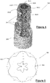
- the 4x4 MIMO omnidirectional antenna 300 comprises a six antenna columns 302A, 302B, 302C, 302D, 302E, 302F arranged in a substantially hexagonal arrangement such that the transverse cross-section of the antenna columns 302A-302F in the 4x4 MIMO omnidirectional antenna 300 will be substantially hexagonal in shape.
- Each of the six antenna columns 302A, 302B, 302C, 302D, 302E, 302F is substantially rectangular in shape such as to comprise side edges 310, 312, a top edge 314 and a bottom edge 316 whereby the side edges 310, 312 are longer than the top edge 314 and the bottom edge 316.
- the six antenna columns 302A-302F are each positioned adjacent to two of the remaining antenna columns along their side edges 310, 312, such that the six antenna columns 302A-302F are arranged to have a substantially hexagonal transverse cross-section. It is very important to arrange the six antenna columns 302A-302F in as tight a pattern as possible, for creating the smallest form factor possible, and also for improvements in the radiation pattern. It is not desirous to separate the six antenna columns 302A-302F away from one another and thus it is an aspect of the present invention that each of the six antenna columns 302A-302F are in abutment, along their side edges, with their two adjacent antenna columns 302A-302F. This encourages the transverse cross-sectional diameter of the 4x4 MIMO omnidirectional antenna 300 to be as small as possible.
- Each of the six antenna columns 302A-302F has a plurality of radiators 304 mounted thereto.
- the radiators 304 are mounted in a substantially vertical manner and in a linear fashion along the length of the rectangular-shaped antenna columns 302A-302F.
- These radiators 304 are dual polarised antenna elements which can radiate two signals at the same time by virtue of their dual polarisation.
- a radome 306 encases the radiators 304 and the antenna columns 302A-302F.
- the relatively small diameter and height of the radome 306 is an important aspect of the present design as this will minimise the overall size of the antenna 300 and make it less of an eyesore when deployed in public spaces.
- the signals on these four ports shall be connected to the radiators of the antenna columns 302A-302F.
- two of the four ports are connected to three of the six antenna columns 302A, 302C, 302E and the other two ports are connected to the other three antenna columns 302B, 302D, 302F of the 4x4 MIMO omnidirectional antenna 300.
- the antenna columns 302A-302F are configured such that an antenna column (e.g. 302A) connected to two of the antenna ports is situated intermediate two adjacent antenna columns (e.g.
- each column set comprising two antenna columns and each column set receiving all of the four input signals, are this established.
- the arrangement of the three column sets formed by the pairs of antenna columns 302A/302B, 302C/302D, 302E/302F is centrosymmetric about a central point of the 4x4 MIMO omnidirectional antenna 300, and each antenna column 302A-302F is axisymmetric about a radially-directed axis which extends between the centre point of the 4x4 MIMO omnidirectional antenna 300 and a transverse cross-sectional midpoint on the antenna column 302A-302F.
- the radiation pattern established by each of the three or more column sets is thus centrosymmetric about the centre point of the 4x4 MIMO omnidirectional antenna 300, and, is also axisymmetric about the radially-directed axis.
- the 4x4 MIMO omnidirectional antenna 300 of the present invention is intended to transmit over the 4900MHz to 6100MHz frequency range, the 3300MHz to 3800MHz frequency range, the 2300MHz to 3800MHz frequency range, the 1710MHz to 2690MHz frequency range, the 698MHz to 960MHz frequency range, and combinations of these mentioned frequency ranges.
- a mechanism (not shown) to allow the 4x4 MIMO omnidirectional antenna 300 to act as a fixed tilt or a variable tilt omnidirectional antenna are envisaged to be employed in some embodiments of the invention.
- the advantages of the 4x4 MIMO omnidirectional antenna 300 of the present invention are that the 4x4 MIMO omnidirectional antenna 300 can be provided in a single radome 306 cover that is of a relatively small diameter. This allows for an ultra-compact design.
- the radome 306 as shown in Figure 4 will have a smaller diameter than the radome 208 of Figure 2c , and a shorter radome height than the radome 205 of Figure 2b .
- the radiators mounted on the antenna columns of the the 4x4 MIMO omnidirectional antenna 300 of the present invention are separated by 60° from adjacent radiators on adjacent antenna columns as adjacent antenna columns are offset by 60° relative to each other such as to form the hexagonal shaped antenna 300. Therefore, the isolation between adjacent antenna columns is considered to be good when compared to the side-by-side configuration of the prior art, where the radiators are very close to each other and alternate adjacent antenna columns are on the same plane and not offset relative to each other.
- the ripple effect is lessened when the centrosymmetric and axisymmetric requirements are met as the radiation pattern generated and radiated will be substantially symmetrical (both centrosymmetric and axisymmetric) and this results in the radiation pattern overlap at the edges of each sector of the radiation pattern being relatively similar on both sides. This improves the ripple effect and increases the omnidirectional coverage area afforded by the antenna design.
- the 4x4 MIMO omnidirectional antenna 300 of the present invention can be used as a dual band 2x2 MIMO omnidirectional antenna.
- the 8x8 MIMO omnidirectional antenna 800 comprises a twelve antenna columns 802A, 802B, 802C, 802D, 802E, 802F, 802G, 802H, 802I, 802J, 802K, 802L arranged in a substantially dodecagonal arrangement such that the transverse cross-section of the antenna columns 802A-802L in the 8x8 MIMO omnidirectional antenna 800 will be substantially dodecagonal in shape.
- Each of the twelve antenna columns 802A, 802B, 802C, 802D, 802E, 802F, 802G, 802H, 802I, 802J, 802K, 802L is substantially rectangular in shape such as to comprise side edges, a top edge, and a bottom edge, whereby the side edges are longer than the top edge and the bottom edge respectively, as in the previous 4x4 MIMO omnidirectional antenna embodiment.
- the twelve antenna columns 802A-802L are each positioned adjacent to two of the remaining antenna columns along their side edges, such that the twelve antenna columns 802A-802L are arranged to have a substantially dodecagonal transverse cross-section. It is again important to arrange the twelve antenna columns 802A-802L in as tight a pattern as possible, for creating the smallest form factor possible, and also for improvements in the radiation pattern. It is not desirous to separate the twelve antenna columns 802A-802L away from one another and thus it is an aspect of the present invention that each of the twelve antenna columns 802A-802L are in abutment, along their side edges, with their two adjacent antenna columns 802A-802L.
- Each of the twelve antenna columns 802A-802L has a plurality of radiators 804 mounted thereto. In a preferred embodiment as shown in Figure 8 , there are six radiators 804 mounted on each of the twelve antenna columns 802A-802L.
- the radiators 804 are mounted in a substantially vertical manner and in a linear fashion along the length of the rectangular-shaped antenna columns 802A-802L.
- These radiators 804 are preferably dual polarised antenna elements which can radiate two signals at the same time by virtue of their dual polarisation.
- a radome 806 encases the radiators 804 and the antenna columns 802A-802L.
- the relatively small diameter and height of the radome 806 is an important aspect of the present design as this will minimise the overall size of the antenna 800 and make it less of an eyesore when deployed in public spaces.
- a 8x8 MIMO omnidirectional antenna 800 will have eight ports (not shown) to receive eight signals to be sent using the 8x8 MIMO omnidirectional antenna 800, the signals on these eight ports shall be connected to the radiators of the antenna columns 802A-802L.
- a first pair of the eight ports is connected to a first group of three of the twelve antenna columns 802A-802L.
- a second pair of the eight ports is connected to a second group of three of the twelve antenna columns 802A-802L.
- a third pair of the eight ports is connected to a third group of three of the twelve antenna columns 802A-802L.
- a fourth and final pair of the eight ports is connected to a fourth group of three of the twelve antenna columns 802A-802L.
- the antenna columns 802A-802L are configured such that one of the antenna columns (e.g. 802A) in the first group is situated adjacent one of the antenna columns (e.g. 802B) in the second group; with said antenna column (e.g. 802B) in the second group being situated adjacent one of the antenna columns (e.g. 802C) in the third group; and said antenna column (e.g. 802C) in the third group being situated adjacent one of the antenna columns (e.g. 802D) in the fourth group.
- one antenna column from each of the groups is arranged side-by-side into a column set comprising four antenna columns.
- each column set comprising four antenna columns and each column set receiving all of the eight input signals, are this established.
- the arrangement of the three column sets formed by the groups of antenna columns 802A/802B/802C/803D, 802E/802F/802G/802H, 802I/802J/802K/802L is centrosymmetric about a central point of the 8x8 MIMO omnidirectional antenna 800, and each antenna column 802A-802L is axisymmetric about a radially-directed axis which extends between the centre point of the 8x8 MIMO omnidirectional antenna 800 and a transverse cross-sectional midpoint on the antenna column 802A-802L.
- the radiation pattern established by each of the three or more column sets is thus centrosymmetric about the centre point of the 8x8 MIMO omnidirectional antenna 800, and, is also axisymmetric about the radially-directed axis.
- references to antenna components being centrosymmetric in the preceding specification will be understood to refer to the antenna components being symmetric about a central point/region when the transverse cross-sectional view of the antenna and antenna components is observed.
- References to antenna components being axisymmetric in the preceding specification will be understood to refer to the antenna components being symmetric about a certain axis.
- antenna and “antenna array” shall be understood to refer to the same apparatus and have been used interchangeably in the preceding specification.
Landscapes
- Engineering & Computer Science (AREA)
- Computer Networks & Wireless Communication (AREA)
- Variable-Direction Aerials And Aerial Arrays (AREA)
Abstract
Description
- This present invention relates to a particular design of a Multiple-Input Multiple-Output (MIMO) omnidirectional antenna. The present invention is further directed towards a first example of such a design which realises a 4x4 MIMO omnidirectional antenna, and a second example of such a design which realises an 8x8 MIMO omnidirectional antenna. Alternative variants of higher order MIMO omnidirectional antennas also fit with the design of the present invention and all are considered to be within the scope of the present invention.
- MIMO systems have long been considered as an effective way to increase the data throughput along a radio frequency channel by utilising the multi-path propagation which will occur naturally in transmission environments. The multipath propagation allows multiple data streams to be transmitted over the same channel, by using multiple antennas on the transmitter side and multiple antennas on the receiver side.
- MIMO has become an essential part of a plurality of wireless communications standards, such as IEEE 802.11n, IEEE 802.11ac, HSPA+, WiMAX, and 4G Long Term Evolution and the emerging 5G standard.
- Throughout the following specification, reference to a "column set" shall be understood to refer to two or more columns which act to form a section of radiation coverage over a portion of the 360° coverage area covered by the omnidirectional antenna. For example, if an omnidirectional antenna comprises three columns sets, then the antenna columns in each of the three column sets will act to cover approximately 120° of the 360 ° coverage area. On the other hand, if there are six column sets, then the antenna columns in each of the six columns sets will act to cover substantially 60° of the 360° coverage area of the omnidirectional antenna.
- Throughout the following specification, reference to an "antenna column" shall be understood to refer to an outwardly facing component of the antenna which will mount one or more antenna radiator elements which directs the beam of radiation from the radiators.
- Throughout the following specification, reference to a "radiator", an "antenna radiator", a "radiator element", a "radiation element", and/or an "antenna radiation element" shall be understood to refer to the component of the antenna which transmits/radiates the antenna beam.
- 2x2 MIMO omnidirectional antennas are used to transmit approximately double the amount of data over a radio frequency channel compared to a single, typical antenna arrangement. The 2x2 MIMO omnidirectional antenna arrangement achieves this doubling of throughput by using two antennas, co-located on the transmitter side, and, two antennas co-located on the receiver side. 2x2 MIMO omnidirectional antennas are deployed in the real world at present and have achieved great commercial success.
- For the 2x2 MIMO omnidirectional antenna, a three- or four-sided design may be used. The three-sided type of design is shown in
Figure 1a and Figure 1b shows the type of radiation pattern which this three-sided 2x2 MIMO omnidirectional antenna produces. The three-sided 2x2 MIMO omnidirectional antenna comprises threeantenna columns radome 106. The 2x2 MlMO omnidirectional antenna is popular for microcell deployments, where a low power base station is used to form the microcell in a mobile phone network. The coverage afforded by the low power base station in the microcell is determined by using power control so as to limit the range of the microcell's coverage area. Depending on the frequency range being used, the typical range of a microcell is a few hundred metres and is usually less than two kilometres wide, whereas standard base stations deployed on a macrocell may have ranges of up to 40 kilometres. Referring toFigure 1b and theradiation plot 108, it can be seen that the level of ripple, which is defined by the range of signal loss in dB between thestrongest signal 110 and theweakest signal 112, is relatively small (approx. 1.5dB) and is considered to be more than acceptable. - The 2x2 MIMO omnidirectional antenna typically consist of +/- 45° polarisations or H&V polarisations. The +/-45° omnidirectional antennas are often referred to as a Pseudo Omni, or Quasi Omni, as they do not have a perfect omnidirectional pattern, which would be substantially circular in nature when viewed on a radiation polar plot. As can be seen in
Figure 1 b , ripple is present on a 2x2 MIMO omnidirectional antenna pattern and this ripple causes deviation from a perfectly circular pattern. The amount of ripple can vary depending on which antenna manufacturer constructed the antenna and the construction techniques they used. In general, a +/- 1.5dB ripple would be considered to be very good and this level of ripple is shown inFigure 1b ; +/-3.0dB ripple would be deemed to be acceptable and higher levels of ripple are not acceptable as issues will arise with coverage throughout the microcell. - As mentioned above, 2x2 MIMO omnidirectional antennas with very good or acceptable levels of ripple are commercially deployed and popular for microcells as the antenna design allows for a relatively compact antenna to fit within a radome, which is a tubular cover for the antenna, having a relatively small diameter.
- Focus has now turned to 4x4 MIMO omnidirectional antennas in order to achieve a further approximate doubling of throughput again.
- The development and popularity of microcells, particularly in built up urban areas, requires relatively small antennas which will not be an eyesore when installed on a side of a building or on a street lamp or power line post. Thus, it is desirable to use an antenna design which is ultra-compact yet delivers good and relatively uniform coverage across the cell by having low levels of ripple.
- A commercially deployed solution for providing a 4x4 MIMO omnidirectional antenna has been to provide two 2x2 MIMO omnidirectional antennas in a physically separated arrangement. This arrangement is shown in
Figure 2a . The 4x4 MIMOomnidirectional antenna 200 of the prior art comprises two 2x2 MIMOomnidirectional antennas 100 as are known in the prior art and which are physically separated by apredefined distance 202. Thispredefined distance 202 is usually 10 times the wavelength (λ) of the transmission wave. This arrangement is easy to deploy but is undesirable as the overall size of the arrangement is relatively large and is widely considered to be an eyesore, particularly in urban environments. - An alternative is to use two 2x2 MlMO omnidirectional antennas which are stacked. This arrangement is shown in
Figure 2b . The 4x4 MIMOomnidirectional antenna 204 of the prior art comprises two 2x2 MIMOomnidirectional antennas radome 205. This retains a relativelysmall radome 205 diameter, however the height of theradome 205 is doubled. Aside from the increase in height of theradome 205 which is undesirable, there are also issues with a loss of signal strength as the signal for the upper 2x2 MIMOomnidirectional antenna 100B needs to be delivered approximately one metre higher than the signal for the lower 2x2 MIMOomnidirectional antenna 100A. This extra cabling length results in approximately 0.5dB loss in signal strength. Yet a further issue with the 'stacked' design approach is that the upper and lower 2x2 MIMOomnidirectional antennas - It has been shown that the benefits of MIMO, when using vertically stacked antenna arrays, is less than that given when the antenna arrays are deployed in a side-by-side fashion. In particular, the side-by-side antenna array shows increased data throughput and the side-by-side antenna array therefore provides higher capacity than the vertically stacked antenna arrays. Instead of stacking two 2x2 MIMO omnidirectional antennas, it has therefore been proposed to provide two 2x2 MIMO omnidirectional antenna in a side-by-side arrangement. This is shown in
Figure 2c . The 4x4 MIMOomnidirectional antenna 206 of the prior art comprises sixantenna columns antenna columns 210A/210B, 210C/210D, 210E/210F arranged side-by-side to form a three-sided omnidirectional antenna housed within aradome 208. Each of the pairs ofantenna columns 210A/210B, 210C/210D, 210E1210F arranged side-by-side form one of three column sets. The diameter of theradome 208 for the side-by-side approach is quite large and this is unwelcome. Moreover, the side-by-side arrangement of the radiators on theantenna columns 210A-F causes a larger ripple effect of the radiation pattern which can exceed +/-5.0dB as is seen fromFigure 2d . Theradiation plot 212 inFigure 2d shows someacceptable signal strength 214 in some directions, but effectivelynull areas 216 in other directions. This is beyond the acceptable levels of ripple for microcell coverage and therefore, the 4x4 MIMOomnidirectional antennas 206 using the side-by-side arrangement are not foreseen to be tolerable for many real world deployments. - A further alternative is to utilise phase shifting to effect a 4x4 MIMO omnidirectional antenna. PCT Patent Application Number
PCT/AU2011/000365 reference numeral 600, shown inFigure 6 . - It is a goal of the present invention to provide a method and/or apparatus that overcomes at least one of the above mentioned problems by providing a MIMO omnidirectional antenna which displays low, acceptable levels of ripple whilst maintaining a compact structure.
- The present invention is directed to a Multiple-Input Multiple-Output (MIMO) omnidirectional antenna comprising three or more column sets, where the three or more column sets are arranged in a centrosymmetric arrangement about a centre point of the antenna; each column set comprising two or more antenna columns and each of the antenna columns mounting a plurality of radiators thereon; whereby, each antenna column receives no more than two signals to be transmitted, and, each of the antenna columns is arranged to be axisymmetric about a radially-directed axis which extends between the centre point of the antenna and a transverse cross-sectional midpoint on the antenna column; such that, each radiation pattern established by each of the three or more column sets is centrosymmetric about the centre point of the antenna, and, is also axisymmetric about the radially-directed axis.
- The advantage of providing the MIMO omnidirectional antenna with antenna columns which are arranged to be axisymmetric about a radially-directed axis created between the centre point of the antenna and a transverse cross-sectional midpoint on the antenna column is that the radiation pattern generated and radiated will be substantially symmetrical (both centrosymmetric and axisymmetric) and this results in the radiation pattern overlap at the edges of each sector of the radiation pattern being relatively similar on both sides. This improves the ripple effect and increases the omnidirectional coverage area afforded by the antenna design. The columns sets are arranged to be symmetrical (centrosymmetric) and within the column sets, the antenna columns are also arranged to be symmetrical. This further symmetrical arrangement within an existing symmetrical arrangement provides the advantages of the present invention.
- In a further embodiment, the Multiple-Input Multiple-Output (MIMO) omnidirectional antenna is directed to a 4x4 Multiple-Input Multiple-Output (MIMO) antenna comprising six antenna columns arranged in a hexagonal arrangement, and/or, a 8x8 Multiple-Input Multiple-Output (MIMO) antenna comprising twelve antenna columns arranged in a dodecagonal arrangement.
- In a further embodiment, each radiation pattern established by each of the three or more column sets is both centrosymmetric and axisymmetric for both amplitude and phase.
- In a further embodiment, the Multiple-Input Multiple-Output (MIMO) omnidirectional antenna comprises three column sets.
- In a further embodiment, the Multiple-Input Multiple-Output (MIMO) omnidirectional antenna comprises three column sets, and each column set comprises two antenna columns.
- In a further embodiment, the Multiple-Input Multiple-Output (MIMO) omnidirectional antenna comprises three column sets, and each column set comprises four antenna columns.
- In a further embodiment, the Multiple-Input Multiple-Output (MIMO) omnidirectional antenna comprises six column sets.
- In a further embodiment, the Multiple-Input Multiple-Output (MIMO) omnidirectional antenna comprises a 4x4 Multiple-Input Multiple-Output omnidirectional antenna comprising a plurality of radiators mounted on six antenna columns, with each of the six antenna columns mounting a plurality of radiators; each of the six antenna columns being substantially rectangular in shape such as to comprise side edges, a top edge and a bottom edge whereby the side edges are longer than the top and bottom edges; each of the six antenna columns being positioned adjacent to two of the remaining antenna columns along its side edges, such that the six antenna columns are arranged to have a substantially hexagonal transverse cross-section; wherein the 4x4 Multiple-Input Multiple-Output omnidirectional antenna comprises four antenna ports for receiving four signals to be transmitted; two of the four ports being connected to three of the six antenna columns and the other two ports being connected to the other three antenna columns; whereby, the antenna columns are configured such that an antenna column connected to two of the antenna ports is situated intermediate two adjacent antenna columns connected to the other two ports.
- This is a hexagonally-arranged 4x4 MIMO version of the present omnidirectional antenna invention.
- In a further embodiment, the Multiple-Input Multiple-Output (MIMO) omnidirectional antenna comprises a 8x8 Multiple-Input Multiple-Output omnidirectional antenna comprising a plurality of radiators mounted on twelve antenna columns, with each of the twelve antenna columns mounting a plurality of radiators; each of the twelve antenna columns being substantially rectangular in shape such as to comprise side edges, a top edge and a bottom edge whereby the side edges are longer than the top and bottom edges; each of the twelve antenna columns being positioned adjacent to two of the remaining antenna columns along its side edges, such that the twelve antenna columns are arranged to have a substantially dodecagonal transverse cross-section; wherein the 8x8 Multiple-Input Multiple-Output omnidirectional antenna comprises eight antenna ports for receiving eight signals to be transmitted; a first pair of the eight ports being connected to a first group of three of the twelve antenna columns; a second pair of the eight ports being connected to a second group of three of the twelve antenna columns; a third pair of the eight ports being connected to a third group of three of the twelve antenna columns; and a fourth pair of the eight ports being connected to a fourth group of three of the twelve antenna columns; whereby, the antenna columns are configured such that one of the antenna columns in the first group is situated adjacent one of the antenna columns in the second group; with said antenna column in the second group being situated adjacent one of the antenna columns in the third group; and said antenna column in the third group being situated adjacent one of the antenna columns in the fourth group.
- This is a dodecagonally-arranged 8x8 MIMO version of the present omnidirectional antenna invention.
- The present invention is further directed to a 4x4 Multiple-Input Multiple-Output omnidirectional antenna comprising a plurality of radiators mounted on six antenna columns, with each of the six antenna columns mounting a plurality of radiators; each of the six antenna columns being substantially rectangular in shape such as to comprise side edges, a top edge and a bottom edge whereby the side edges are longer than the top and bottom edges; each of the six antenna columns being positioned adjacent to two of the remaining antenna columns along its side edges, such that the six antenna columns are arranged to have a substantially hexagonal transverse cross-section; wherein the 4x4 Multiple-Input Multiple-Output omnidirectional antenna comprises four antenna ports for receiving four signals to be transmitted; two of the four ports being connected to three of the six antenna columns and the other two ports being connected to the other three antenna columns; whereby, the antenna columns are configured such that an antenna column connected to two of the antenna ports is situated intermediate two adjacent antenna columns connected to the other two ports.
- The advantage of providing the columns making up the 4x4 MIMO omnidirectional antenna in a hexagonal arrangement is that the antenna can fit within a radome of relatively small diameter, whilst the radiation plot coverage provided by the 4x4 MIMO omnidirectional antenna will be uniform across a microcell where the 4x4 MIMO omnidirectional antenna is deployed, and all of the ports of the 4x4 MIMO omnidirectional antenna will have a substantially similar gain. As no phase shifting is required to transmit all of the four input signals using this technique of grouping the columns into three column sets (each column set comprising a pair of columns), the ripple on the radiation plot will be kept to acceptable levels.
- In a further embodiment, each of the six antenna columns comprises four radiators. In a further embodiment, each of the six antenna columns comprises six radiators. In a further embodiment, each of the six antenna columns comprises eight radiators.
- In a further embodiment, the radiators are mounted substantially vertically in a linear fashion along the length of the rectangular-shaped antenna columns.
- In a further embodiment, the antenna operates as a dual band 2x2 Multiple-Input Multiple-Output omnidirectional antenna.
- In a further embodiment, the 4x4 Multiple-Input Multiple-Output omnidirectional antenna is housed within a tubular shaped radome.
- In a further embodiment, the 4x4 Multiple-Input Multiple-Output omnidirectional antenna operates in one or more of: the 4900MHz to 6100MHz frequency range, the 3300MHz to 3800MHz frequency range, the 2300MHz to 3800MHz frequency range, the 1710MHz to 2690MHz frequency range, and, the 689MHz to 960MHz frequency range.
- The present invention is further directed to a 8x8 Multiple-Input Multiple-Output omnidirectional antenna comprising a 4x4 Multiple-Input Multiple-Output omnidirectional antenna as hereinbefore described stacked on top of a second 4x4 Multiple-Input Multiple-Output omnidirectional antenna as hereinbefore described.
- In a further embodiment, the 4x4 Multiple-Input Multiple-Output omnidirectional antenna does not comprise any radiators which use vertical polarised antennas. Such antennas are known to have poor decorrelation between ports.
- The present invention is further directed to a 8x8 Multiple-Input Multiple-Output omnidirectional antenna comprising a plurality of radiators mounted on twelve antenna columns, with each of the twelve antenna columns mounting a plurality of radiators; each of the twelve antenna columns being substantially rectangular in shape such as to comprise side edges, a top edge and a bottom edge whereby the side edges are longer than the top and bottom edges; each of the twelve antenna columns being positioned adjacent to two of the remaining antenna columns along its side edges, such that the twelve antenna columns are arranged to have a substantially dodecagonal transverse cross-section; wherein the 8x8 Multiple-Input Multiple-Output omnidirectional antenna comprises eight antenna ports for receiving eight signals to be transmitted; a first pair of the eight ports being connected to a first group of three of the twelve antenna columns; a second pair of the eight ports being connected to a second group of three of the twelve antenna columns; a third pair of the eight ports being connected to a third group of three of the twelve antenna columns; and a fourth pair of the eight ports being connected to a fourth group of three of the twelve antenna columns; whereby, the antenna columns are configured such that one of the antenna columns in the first group is situated adjacent one of the antenna columns in the second group; with said antenna column in the second group being situated adjacent one of the antenna columns in the third group; and said antenna column in the third group being situated adjacent one of the antenna columns in the fourth group.
- In this manner, one antenna column from each of the groups is arranged side-by-side into a column set comprising four antenna columns. There are three such column sets, and the three column sets are arranged in the dodecagonal shape of the 8x8 MIMO omnidirectional antenna so as to be centrosymmetric about the centre point of the antenna, and to be axisymmetric about the radially-directed axis.
- The invention will be more clearly understood from the following description of some embodiments thereof, given by way of example only, with reference to the accompanying drawings, in which:
-
Figure 1a is a perspective view of a 2x2 MIMO omnidirectional antenna of the prior art; -
Figure 1b is a polar radiation plot for the 2x2 MIMO omnidirectional antenna ofFigure 1a ; -
Figure 2a is a perspective view of a 4x4 MIMO omnidirectional antenna of the prior art, formed by two, physically separated 2x2 MIMO omnidirectional antennas; -
Figure 2b is a perspective view of a 4x4 MIMO omnidirectional antenna of the prior art, formed by two, stacked 2x2 MIMO omnidirectional antennas; -
Figure 2c is a perspective view of a 4x4 MIMO omnidirectional antenna of the prior art, formed by two, side-by-side 2x2 MIMO omnidirectional antennas; -
Figure 2d is a polar radiation plot for the 4x4 MIMO omnidirectional antenna ofFigure 2c ; -
Figure 3 is a perspective view of a 4x4 MIMO omnidirectional antenna, in accordance with the present invention; -
Figure 4 is a perspective view of the 4x4 MIMO omnidirectional antenna ofFigure 3 , partially encased by a radome in accordance with the present invention; -
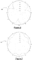
Figure 5 is a polar radiation plot for the 4x4 MIMO omnidirectional antenna ofFigure 3 ; -
Figure 6 is a polar radiation plot for a MIMO omnidirectional antenna of the prior art, which utilises Butler matrices for phase shifting signals to be transmitted; -
Figure 7 is a polar radiation plot for the MIMO omnidirectional antenna of the present invention; and -
Figure 8 is a perspective view of an 8x8 MIMO omnidirectional antenna of the present invention. - It will be understood that the general concept of the present invention may be described in terms of the principles for the design of the innovative antenna having particular characteristics regarding the number of column sets, the number of antenna columns in each column set, the symmetry of the column sets, the symmetry of the antenna columns, the symmetry of the radiation plots from the column sets, and, the number of input signal connections delivered to each antenna column. The invention is described in more detail in respect of an example of a 4x4 MIMO omnidirectional antenna which follows the principles of the present invention and has a hexagonal arrangement, and, also an 8x8 MIMO omnidirectional antenna which follows the principles of the present invention and has a dodecagonal arrangement.
- The general principle of the present invention can be described as a Multiple-Input Multiple-Output (MIMO) omnidirectional antenna comprising three or more column sets, where the three or more column sets are arranged in a centrosymmetric arrangement about a centre point of the antenna; each column set comprising two or more antenna columns and each of the antenna columns mounting a plurality of radiators thereon; whereby, each antenna column receives no more than two signals to be transmitted, and, each of the antenna columns is arranged to be axisymmetric about a radially-directed axis which extends between the centre point of the antenna and a transverse cross-sectional midpoint on the antenna column itself; such that, each radiation pattern established by each of the three or more column sets is centrosymmetric about the centre point of the antenna, and, is axisymmetric about the radially-directed axis. This is beneficial in comparison to other MIMO omnidirectional antennas known from the art, as this design of antenna provides better omnidirectional coverage over the microcell where the MIMO omnidirectional antenna is deployed. Referring to
Figure 7 , such a radiation plot is shown and indicated generally byreference numeral 700, and, the improvement in coverage, when compared to the radiation plot of the prior art (Figure 6 ), is clearly seen. - Looking at the 4x4 MIMO omnidirectional antenna example in particular detail, and referring to
Figures 3 and4 , there is provided a 4x4 MIMO omnidirectional antenna indicated generally byreference numeral 300. The 4x4 MIMOomnidirectional antenna 300 comprises a sixantenna columns antenna columns 302A-302F in the 4x4 MIMOomnidirectional antenna 300 will be substantially hexagonal in shape. - Each of the six
antenna columns top edge 314 and abottom edge 316 whereby the side edges 310, 312 are longer than thetop edge 314 and thebottom edge 316. - The six
antenna columns 302A-302F are each positioned adjacent to two of the remaining antenna columns along theirside edges antenna columns 302A-302F are arranged to have a substantially hexagonal transverse cross-section. It is very important to arrange the sixantenna columns 302A-302F in as tight a pattern as possible, for creating the smallest form factor possible, and also for improvements in the radiation pattern. It is not desirous to separate the sixantenna columns 302A-302F away from one another and thus it is an aspect of the present invention that each of the sixantenna columns 302A-302F are in abutment, along their side edges, with their twoadjacent antenna columns 302A-302F. This encourages the transverse cross-sectional diameter of the 4x4 MIMOomnidirectional antenna 300 to be as small as possible. - Each of the six
antenna columns 302A-302F has a plurality ofradiators 304 mounted thereto. In a preferred embodiment as shown inFigure 3 , there are fourradiators 304 mounted on each of the sixantenna columns 302A-302F. Theradiators 304 are mounted in a substantially vertical manner and in a linear fashion along the length of the rectangular-shapedantenna columns 302A-302F. Theseradiators 304 are dual polarised antenna elements which can radiate two signals at the same time by virtue of their dual polarisation. - A
radome 306 encases theradiators 304 and theantenna columns 302A-302F. The relatively small diameter and height of theradome 306 is an important aspect of the present design as this will minimise the overall size of theantenna 300 and make it less of an eyesore when deployed in public spaces. - As a 4x4 MIMO
omnidirectional antenna 300 will have four ports (not shown) to receive four signals to be sent using the 4x4 MIMOomnidirectional antenna 300, the signals on these four ports shall be connected to the radiators of theantenna columns 302A-302F. In a preferred embodiment, two of the four ports are connected to three of the sixantenna columns antenna columns omnidirectional antenna 300. In this way, theantenna columns 302A-302F are configured such that an antenna column (e.g. 302A) connected to two of the antenna ports is situated intermediate two adjacent antenna columns (e.g. 302B and 302F) which are connected to the other two ports of the four ports of the 4x4 MIMOomnidirectional antenna 300. Three columns sets, with each column set comprising two antenna columns and each column set receiving all of the four input signals, are this established. The arrangement of the three column sets formed by the pairs ofantenna columns 302A/302B, 302C/302D, 302E/302F is centrosymmetric about a central point of the 4x4 MIMOomnidirectional antenna 300, and eachantenna column 302A-302F is axisymmetric about a radially-directed axis which extends between the centre point of the 4x4 MIMOomnidirectional antenna 300 and a transverse cross-sectional midpoint on theantenna column 302A-302F. The radiation pattern established by each of the three or more column sets is thus centrosymmetric about the centre point of the 4x4 MIMOomnidirectional antenna 300, and, is also axisymmetric about the radially-directed axis. - In preferred embodiments, the 4x4 MIMO
omnidirectional antenna 300 of the present invention is intended to transmit over the 4900MHz to 6100MHz frequency range, the 3300MHz to 3800MHz frequency range, the 2300MHz to 3800MHz frequency range, the 1710MHz to 2690MHz frequency range, the 698MHz to 960MHz frequency range, and combinations of these mentioned frequency ranges. - A mechanism (not shown) to allow the 4x4 MIMO
omnidirectional antenna 300 to act as a fixed tilt or a variable tilt omnidirectional antenna are envisaged to be employed in some embodiments of the invention. - The advantages of the 4x4 MIMO
omnidirectional antenna 300 of the present invention are that the 4x4 MIMOomnidirectional antenna 300 can be provided in asingle radome 306 cover that is of a relatively small diameter. This allows for an ultra-compact design. Theradome 306 as shown inFigure 4 will have a smaller diameter than theradome 208 ofFigure 2c , and a shorter radome height than theradome 205 ofFigure 2b . - There will be similar radiation plot patterns for each of the four ports as they are emitted using the same antenna radiators on the same horizontal plane. This is shown in
Figure 5 , where theradiation plot 500 shows the ripple effect between thestrongest signal directions 502 and theweaker signal directions 504 is acceptable. - As the cabling feeding the four ports will be the same length, there will be the same gains for each of the four ports also.
- The radiators mounted on the antenna columns of the the 4x4 MIMO
omnidirectional antenna 300 of the present invention are separated by 60° from adjacent radiators on adjacent antenna columns as adjacent antenna columns are offset by 60° relative to each other such as to form the hexagonal shapedantenna 300. Therefore, the isolation between adjacent antenna columns is considered to be good when compared to the side-by-side configuration of the prior art, where the radiators are very close to each other and alternate adjacent antenna columns are on the same plane and not offset relative to each other. - The ripple effect is lessened when the centrosymmetric and axisymmetric requirements are met as the radiation pattern generated and radiated will be substantially symmetrical (both centrosymmetric and axisymmetric) and this results in the radiation pattern overlap at the edges of each sector of the radiation pattern being relatively similar on both sides. This improves the ripple effect and increases the omnidirectional coverage area afforded by the antenna design.
- In other embodiments, the 4x4 MIMO
omnidirectional antenna 300 of the present invention can be used as a dual band 2x2 MIMO omnidirectional antenna. - Referring now to
Figure 8 , there is provided an 8x8 MIMO omnidirectional antenna indicated generally byreference numeral 800. The 8x8 MIMOomnidirectional antenna 800 comprises a twelveantenna columns antenna columns 802A-802L in the 8x8 MIMOomnidirectional antenna 800 will be substantially dodecagonal in shape. Each of the twelveantenna columns - The twelve
antenna columns 802A-802L are each positioned adjacent to two of the remaining antenna columns along their side edges, such that the twelveantenna columns 802A-802L are arranged to have a substantially dodecagonal transverse cross-section. It is again important to arrange the twelveantenna columns 802A-802L in as tight a pattern as possible, for creating the smallest form factor possible, and also for improvements in the radiation pattern. It is not desirous to separate the twelveantenna columns 802A-802L away from one another and thus it is an aspect of the present invention that each of the twelveantenna columns 802A-802L are in abutment, along their side edges, with their twoadjacent antenna columns 802A-802L. This encourages the transverse cross-sectional diameter of the 8x8 MIMOomnidirectional antenna 800 to be as small as possible. Each of the twelveantenna columns 802A-802L has a plurality ofradiators 804 mounted thereto. In a preferred embodiment as shown inFigure 8 , there are sixradiators 804 mounted on each of the twelveantenna columns 802A-802L. Theradiators 804 are mounted in a substantially vertical manner and in a linear fashion along the length of the rectangular-shapedantenna columns 802A-802L. Theseradiators 804 are preferably dual polarised antenna elements which can radiate two signals at the same time by virtue of their dual polarisation. Aradome 806 encases theradiators 804 and theantenna columns 802A-802L. The relatively small diameter and height of theradome 806 is an important aspect of the present design as this will minimise the overall size of theantenna 800 and make it less of an eyesore when deployed in public spaces. - As a 8x8 MIMO
omnidirectional antenna 800 will have eight ports (not shown) to receive eight signals to be sent using the 8x8 MIMOomnidirectional antenna 800, the signals on these eight ports shall be connected to the radiators of theantenna columns 802A-802L. In a preferred embodiment, a first pair of the eight ports is connected to a first group of three of the twelveantenna columns 802A-802L. A second pair of the eight ports is connected to a second group of three of the twelveantenna columns 802A-802L. A third pair of the eight ports is connected to a third group of three of the twelveantenna columns 802A-802L. And, a fourth and final pair of the eight ports is connected to a fourth group of three of the twelveantenna columns 802A-802L. Theantenna columns 802A-802L are configured such that one of the antenna columns (e.g. 802A) in the first group is situated adjacent one of the antenna columns (e.g. 802B) in the second group; with said antenna column (e.g. 802B) in the second group being situated adjacent one of the antenna columns (e.g. 802C) in the third group; and said antenna column (e.g. 802C) in the third group being situated adjacent one of the antenna columns (e.g. 802D) in the fourth group. In this manner, one antenna column from each of the groups is arranged side-by-side into a column set comprising four antenna columns. There are three such column sets, and the three column sets are arranged in the dodecagonal shape of the 8x8 MIMOomnidirectional antenna 800 so as to be centrosymmetric about the centre point of the antenna, and to be axisymmetric about the radially-directed axis. Three columns sets, with each column set comprising four antenna columns and each column set receiving all of the eight input signals, are this established. The arrangement of the three column sets formed by the groups ofantenna columns 802A/802B/ 802C/803D, 802E/802F/ 802G/802H, 802I/802J/ 802K/802L is centrosymmetric about a central point of the 8x8 MIMOomnidirectional antenna 800, and eachantenna column 802A-802L is axisymmetric about a radially-directed axis which extends between the centre point of the 8x8 MIMOomnidirectional antenna 800 and a transverse cross-sectional midpoint on theantenna column 802A-802L. The radiation pattern established by each of the three or more column sets is thus centrosymmetric about the centre point of the 8x8 MIMOomnidirectional antenna 800, and, is also axisymmetric about the radially-directed axis. - References to antenna components being centrosymmetric in the preceding specification will be understood to refer to the antenna components being symmetric about a central point/region when the transverse cross-sectional view of the antenna and antenna components is observed. References to antenna components being axisymmetric in the preceding specification will be understood to refer to the antenna components being symmetric about a certain axis.
- The terms "comprise" and "include", and any variations thereof required for grammatical reasons, are to be considered as interchangeable and accorded the widest possible interpretation.
- It will be understood that the components shown in any of the drawings are not necessarily drawn to scale, and, like parts shown in several drawings are designated the same reference numerals.
- The terms "antenna" and "antenna array" shall be understood to refer to the same apparatus and have been used interchangeably in the preceding specification.
- It will be further understood that features from any of the embodiments may be combined with alternative described embodiments, even if such a combination is not explicitly recited hereinbefore but would be understood to be technically feasible by the person skilled in the art.
- The invention is not limited to the embodiments hereinbefore described which may be varied in both construction and detail.
Claims (15)
- A Multiple-Input Multiple-Output (MIMO) omnidirectional antenna comprising three or more column sets, where the three or more column sets are arranged in a centrosymmetric arrangement about a centre point of the antenna;
each column set comprising two or more antenna columns and each of the antenna columns mounting a plurality of radiators thereon;
whereby, each antenna column receives no more than two signals to be transmitted, and, each of the antenna columns is arranged to be axisymmetric about a radially-directed axis which extends between the centre point of the antenna and a transverse cross-sectional midpoint on the antenna column;
such that, each radiation pattern established by each of the three or more column sets is centrosymmetric about the centre point of the antenna, and, is axisymmetric about the radially-directed axis. - A Multiple-Input Multiple-Output omnidirectional antenna as claimed in claim 1, wherein the Multiple-Input Multiple-Output omnidirectional antenna is a 4x4 Multiple-Input Multiple-Output antenna comprising six antenna columns arranged in a hexagonal arrangement.
- A Multiple-Input Multiple-Output omnidirectional antenna as claimed in claim 1, wherein the Multiple-Input Multiple-Output omnidirectional antenna is a 8x8 Multiple-Input Multiple-Output antenna comprising twelve antenna columns arranged in a dodecagonal arrangement.
- A Multiple-Input Multiple-Output omnidirectional antenna as claimed in any of claims 1 to 3, wherein, each radiation pattern established by each of the three or more column sets is both centrosymmetric and axisymmetric for both amplitude and phase.
- A Multiple-Input Multiple-Output omnidirectional antenna as claimed in claim 1, wherein the Multiple-Input Multiple-Output omnidirectional antenna comprises three column sets.
- A Multiple-Input Multiple-Output omnidirectional antenna as claimed in claim 1, wherein the Multiple-Input Multiple-Output omnidirectional antenna comprises six column sets.
- A Multiple-Input Multiple-Output omnidirectional antenna as claimed in claim 2, wherein the 4x4 Multiple-Input Multiple-Output omnidirectional antenna comprising a plurality of radiators mounted on six antenna columns, with each of the six antenna columns mounting a plurality of radiators;
each of the six antenna columns being substantially rectangular in shape such as to comprise side edges, a top edge and a bottom edge whereby the side edges are longer than the top and bottom edges;
each of the six antenna columns being positioned adjacent to two of the remaining antenna columns along its side edges, such that the six antenna columns are arranged to have a substantially hexagonal transverse cross-section;
wherein, the 4x4 Multiple-Input Multiple-Output omnidirectional antenna comprises four antenna ports for receiving four signals to be transmitted; two of the four ports being connected to three of the six antenna columns and the other two ports being connected to the other three antenna columns;
whereby, the antenna columns are configured such that an antenna column connected to two of the antenna ports is situated intermediate two adjacent antenna columns connected to the other two ports. - A Multiple-Input Multiple-Output omnidirectional antenna as claimed in claim 3, wherein the 8x8 Multiple-Input Multiple-Output omnidirectional antenna comprising a plurality of radiators mounted on twelve antenna columns, with each of the twelve antenna columns mounting a plurality of radiators;
each of the twelve antenna columns being substantially rectangular in shape such as to comprise side edges, a top edge and a bottom edge whereby the side edges are longer than the top and bottom edges;
each of the twelve antenna columns being positioned adjacent to two of the remaining antenna columns along its side edges, such that the twelve antenna columns are arranged to have a substantially dodecagonal transverse cross-section;
wherein, the 8x8 Multiple-Input Multiple-Output omnidirectional antenna comprises eight antenna ports for receiving eight signals to be transmitted; a first pair of the eight ports being connected to a first group of three of the twelve antenna columns;
a second pair of the eight ports being connected to a second group of three of the twelve antenna columns;
a third pair of the eight ports being connected to a third group of three of the twelve antenna columns; and
a fourth pair of the eight ports being connected to a fourth group of three of the twelve antenna columns;
whereby, the antenna columns are configured such that one of the antenna columns in the first group is situated adjacent one of the antenna columns in the second group; with said antenna column in the second group being situated adjacent one of the antenna columns in the third group; and said antenna column in the third group being situated adjacent one of the antenna columns in the fourth group. - A Multiple-Input Multiple-Output omnidirectional antenna as claimed in any preceding claims, wherein, each of the antenna columns comprises four radiators.
- A Multiple-Input Multiple-Output omnidirectional antenna as claimed in any preceding claims, wherein, each of the antenna columns is substantially rectangular in shape such as to comprise side edges, a top edge and a bottom edge whereby the side edges are longer than the top and bottom edges.
- A Multiple-Input Multiple-Output omnidirectional antenna as claimed in claim 10, wherein, the radiators are mounted substantially vertically in a linear fashion along the length of the rectangular-shaped antenna columns.
- A Multiple-Input Multiple-Output omnidirectional antenna as claimed in any preceding claims, wherein, the radiators are dual polarised antenna elements.
- A Multiple-Input Multiple-Output omnidirectional antenna as claimed in any preceding claims, wherein, none of the plurality of radiators are phase shifted.
- A Multiple-Input Multiple-Output omnidirectional antenna as claimed in claim 7, wherein, the antenna operates as a dual band 2x2 Multiple-Input Multiple-Output omnidirectional antenna.
- A Multiple-Input Multiple-Output omnidirectional antenna as claimed in any preceding claims, wherein, the Multiple-Input Multiple-Output omnidirectional antenna is housed within a tubular shaped radome.
Applications Claiming Priority (1)
| Application Number | Priority Date | Filing Date | Title |
|---|---|---|---|
| GBGB1602840.9A GB201602840D0 (en) | 2016-02-18 | 2016-02-18 | A multiple-input multiple-output (MIMO) omnidirectional antenna |
Publications (2)
| Publication Number | Publication Date |
|---|---|
| EP3208887A1 true EP3208887A1 (en) | 2017-08-23 |
| EP3208887B1 EP3208887B1 (en) | 2022-04-06 |
Family
ID=55752838
Family Applications (1)
| Application Number | Title | Priority Date | Filing Date |
|---|---|---|---|
| EP17156780.3A Active EP3208887B1 (en) | 2016-02-18 | 2017-02-17 | A multiple-input multiple-output (mimo) omnidirectional antenna |
Country Status (3)
| Country | Link |
|---|---|
| US (3) | US10164346B2 (en) |
| EP (1) | EP3208887B1 (en) |
| GB (1) | GB201602840D0 (en) |
Cited By (9)
| Publication number | Priority date | Publication date | Assignee | Title |
|---|---|---|---|---|
| EP3382802B1 (en) * | 2017-03-27 | 2021-08-25 | Alpha Wireless Limited | Concealed antenna node |
| US11251539B2 (en) | 2016-07-29 | 2022-02-15 | Airspan Ip Holdco Llc | Multi-band access point antenna array |
| US11289821B2 (en) | 2018-09-11 | 2022-03-29 | Air Span Ip Holdco Llc | Sector antenna systems and methods for providing high gain and high side-lobe rejection |
| US11404796B2 (en) | 2018-03-02 | 2022-08-02 | Airspan Ip Holdco Llc | Omni-directional orthogonally-polarized antenna system for MIMO applications |
| US11482789B2 (en) | 2013-06-28 | 2022-10-25 | Airspan Ip Holdco Llc | Ellipticity reduction in circularly polarized array antennas |
| US11626921B2 (en) | 2014-09-08 | 2023-04-11 | Airspan Ip Holdco Llc | Systems and methods of a Wi-Fi repeater device |
| US11677163B1 (en) * | 2022-02-10 | 2023-06-13 | Communication Components Antenna Inc. | Quasi-omni cylindrical antenna with null-filling sub arrays |
| US11888589B2 (en) | 2014-03-13 | 2024-01-30 | Mimosa Networks, Inc. | Synchronized transmission on shared channel |
| US20250087903A1 (en) * | 2023-09-07 | 2025-03-13 | Mediatek Inc. | Mimo antenna system |
Families Citing this family (17)
| Publication number | Priority date | Publication date | Assignee | Title |
|---|---|---|---|---|
| US10777883B2 (en) * | 2011-08-09 | 2020-09-15 | Envisioneering, Inc. | Phase-conjugate antenna system |
| US10020587B2 (en) * | 2015-07-31 | 2018-07-10 | At&T Intellectual Property I, L.P. | Radial antenna and methods for use therewith |
| CN110402499B (en) | 2017-02-03 | 2023-11-03 | 康普技术有限责任公司 | Small cell antenna suitable for MIMO operation |
| US10530440B2 (en) | 2017-07-18 | 2020-01-07 | Commscope Technologies Llc | Small cell antennas suitable for MIMO operation |
| US10587034B2 (en) | 2017-09-29 | 2020-03-10 | Commscope Technologies Llc | Base station antennas with lenses for reducing upwardly-directed radiation |
| US10892559B2 (en) | 2017-12-06 | 2021-01-12 | Galtronics Usa, Inc. | Dipole antenna |
| US11043755B2 (en) | 2017-12-06 | 2021-06-22 | Galtronics Usa, Inc. | Antenna array |
| US11038286B2 (en) * | 2017-12-06 | 2021-06-15 | Galtronics Usa, Inc. | Antenna array |
| US11271311B2 (en) | 2017-12-21 | 2022-03-08 | The Hong Kong University Of Science And Technology | Compact wideband integrated three-broadside-mode patch antenna |
| CN111490356B (en) | 2019-01-28 | 2025-05-13 | 户外无线网络有限公司 | Compact omnidirectional antenna with stacked reflector structure |
| US11336028B2 (en) * | 2019-06-14 | 2022-05-17 | Communication Components Antenna Inc | Butler-based quasi-omni MIMO antenna |
| WO2021081042A1 (en) * | 2019-10-21 | 2021-04-29 | John Mezzalingua Associates, LLC | Antenna having an internal cable tower and guides for precise cable placement and method for constructing the same |
| CN114762185A (en) | 2019-12-10 | 2022-07-15 | 胡贝尔舒纳公司 | Omnidirectional horizontally polarized antenna with high current protection |
| US11838045B2 (en) * | 2021-09-27 | 2023-12-05 | Saudi Arabian Oil Company | System and method for controlling an antenna system |
| USD1032021S1 (en) * | 2022-02-23 | 2024-06-18 | Brian M. Adams | Geometrical column unit |
| NL2032853B1 (en) * | 2022-08-25 | 2024-03-05 | Poynting Antennas Pty Ltd | Antenna dome assembly |
| US11901624B1 (en) | 2022-10-06 | 2024-02-13 | City University Of Hong Kong | Wideband high-gain omnidirectional biconical antenna for millimeter-wave applications |
Citations (2)
| Publication number | Priority date | Publication date | Assignee | Title |
|---|---|---|---|---|
| US20100119002A1 (en) * | 2008-11-12 | 2010-05-13 | Xirrus, Inc. | Mimo antenna system |
| US20130265197A1 (en) * | 2010-03-31 | 2013-10-10 | Argus Technologies (Australia) Pty Ltd | Omni-directional multiple-input multiple-output antenna system |
Family Cites Families (8)
| Publication number | Priority date | Publication date | Assignee | Title |
|---|---|---|---|---|
| JP3540374B2 (en) | 1994-07-20 | 2004-07-07 | Kddi株式会社 | Base station antenna device for mobile communication system |
| US5923296A (en) | 1996-09-06 | 1999-07-13 | Raytheon Company | Dual polarized microstrip patch antenna array for PCS base stations |
| CN2729936Y (en) | 2004-09-23 | 2005-09-28 | 西安海天天线科技股份有限公司 | Multi-polarization fan region array antenna |
| US20100182203A1 (en) | 2007-06-19 | 2010-07-22 | Agency For Science, Technology And Research | Broadband antenna for wireless communications |
| US8063832B1 (en) | 2008-04-14 | 2011-11-22 | University Of South Florida | Dual-feed series microstrip patch array |
| JP6294769B2 (en) | 2014-06-09 | 2018-03-14 | 日本電信電話株式会社 | ANTENNA DEVICE AND BASE STATION DEVICE |
| KR101547474B1 (en) | 2014-06-13 | 2015-09-04 | 주식회사쏘우웨이브 | Omni directional antennaantenna using electro polarization for MIMO |
| TWI583145B (en) * | 2015-09-22 | 2017-05-11 | 啟碁科技股份有限公司 | RF transceiver system |
-
2016
- 2016-02-18 GB GBGB1602840.9A patent/GB201602840D0/en not_active Ceased
-
2017
- 2017-02-17 EP EP17156780.3A patent/EP3208887B1/en active Active
- 2017-02-20 US US15/436,941 patent/US10164346B2/en active Active
-
2018
- 2018-12-21 US US16/229,352 patent/US10403986B2/en active Active
-
2019
- 2019-07-23 US US16/519,416 patent/US20190348769A1/en not_active Abandoned
Patent Citations (2)
| Publication number | Priority date | Publication date | Assignee | Title |
|---|---|---|---|---|
| US20100119002A1 (en) * | 2008-11-12 | 2010-05-13 | Xirrus, Inc. | Mimo antenna system |
| US20130265197A1 (en) * | 2010-03-31 | 2013-10-10 | Argus Technologies (Australia) Pty Ltd | Omni-directional multiple-input multiple-output antenna system |
Cited By (12)
| Publication number | Priority date | Publication date | Assignee | Title |
|---|---|---|---|---|
| US11482789B2 (en) | 2013-06-28 | 2022-10-25 | Airspan Ip Holdco Llc | Ellipticity reduction in circularly polarized array antennas |
| US11888589B2 (en) | 2014-03-13 | 2024-01-30 | Mimosa Networks, Inc. | Synchronized transmission on shared channel |
| US11626921B2 (en) | 2014-09-08 | 2023-04-11 | Airspan Ip Holdco Llc | Systems and methods of a Wi-Fi repeater device |
| US11251539B2 (en) | 2016-07-29 | 2022-02-15 | Airspan Ip Holdco Llc | Multi-band access point antenna array |
| EP3491697B1 (en) * | 2016-07-29 | 2023-09-13 | Airspan IP Holdco LLC | Multi-band access point antenna array |
| US12316014B2 (en) | 2016-07-29 | 2025-05-27 | Mimosa Networks, Inc. | Multi-band antenna array devices having a tubular configuration |
| EP3382802B1 (en) * | 2017-03-27 | 2021-08-25 | Alpha Wireless Limited | Concealed antenna node |
| US11404796B2 (en) | 2018-03-02 | 2022-08-02 | Airspan Ip Holdco Llc | Omni-directional orthogonally-polarized antenna system for MIMO applications |
| US11637384B2 (en) | 2018-03-02 | 2023-04-25 | Airspan Ip Holdco Llc | Omni-directional antenna system and device for MIMO applications |
| US11289821B2 (en) | 2018-09-11 | 2022-03-29 | Air Span Ip Holdco Llc | Sector antenna systems and methods for providing high gain and high side-lobe rejection |
| US11677163B1 (en) * | 2022-02-10 | 2023-06-13 | Communication Components Antenna Inc. | Quasi-omni cylindrical antenna with null-filling sub arrays |
| US20250087903A1 (en) * | 2023-09-07 | 2025-03-13 | Mediatek Inc. | Mimo antenna system |
Also Published As
| Publication number | Publication date |
|---|---|
| GB201602840D0 (en) | 2016-04-06 |
| US10164346B2 (en) | 2018-12-25 |
| US20190123456A1 (en) | 2019-04-25 |
| US20190348769A1 (en) | 2019-11-14 |
| EP3208887B1 (en) | 2022-04-06 |
| US10403986B2 (en) | 2019-09-03 |
| US20170244176A1 (en) | 2017-08-24 |
Similar Documents
| Publication | Publication Date | Title |
|---|---|---|
| EP3208887B1 (en) | A multiple-input multiple-output (mimo) omnidirectional antenna | |
| US12199715B2 (en) | Small cell beam-forming antennas | |
| EP3488489B1 (en) | Base station antenna system with enhanced array spacing | |
| US9438278B2 (en) | Multi-array antenna | |
| EP3120416B1 (en) | Compact antenna array using virtual rotation of radiating vectors | |
| US7538740B2 (en) | Multiple-element antenna array for communication network | |
| US9293809B2 (en) | Forty-five degree dual broad band base station antenna | |
| US20170062952A1 (en) | Dual band, multi column antenna array for wireless network | |
| US11108137B2 (en) | Compact omnidirectional antennas having stacked reflector structures | |
| EP2741369B1 (en) | Multi-mode antenna and base station | |
| US9698494B2 (en) | Quadri-polarized antenna radiator, quadri-polarized antenna and quadri-polarized multi-antenna array | |
| WO2017121222A1 (en) | Phased array antenna having sub-arrays | |
| US20230170957A1 (en) | Small cell beamforming antennas suitable for use with 5g beamforming radios and related base stations | |
| EP3695459B1 (en) | Cellular antenna for elevated and obstructed deployment | |
| US20150364832A1 (en) | An antenna arrangement and a base station | |
| EP2710668A1 (en) | Tri-pole antenna element and antenna array | |
| CN106716714B (en) | Stadium antenna | |
| US20240047861A1 (en) | Small cell beamforming antennas suitable for use with 5g beamforming radios and related base stations | |
| CN114843742A (en) | Beamforming antenna with omnidirectional coverage in azimuth plane | |
| EP2902931B1 (en) | Array antenna and base station | |
| US7280084B2 (en) | Antenna system for generating and utilizing several small beams from several wide-beam antennas | |
| US20170117627A1 (en) | A Wireless Communication Node With an Antenna Arrangement For Triple Band Reception and Transmission |
Legal Events
| Date | Code | Title | Description |
|---|---|---|---|
| PUAI | Public reference made under article 153(3) epc to a published international application that has entered the european phase |
Free format text: ORIGINAL CODE: 0009012 |
|
| STAA | Information on the status of an ep patent application or granted ep patent |
Free format text: STATUS: THE APPLICATION HAS BEEN PUBLISHED |
|
| AK | Designated contracting states |
Kind code of ref document: A1 Designated state(s): AL AT BE BG CH CY CZ DE DK EE ES FI FR GB GR HR HU IE IS IT LI LT LU LV MC MK MT NL NO PL PT RO RS SE SI SK SM TR |
|
| AX | Request for extension of the european patent |
Extension state: BA ME |
|
| STAA | Information on the status of an ep patent application or granted ep patent |
Free format text: STATUS: REQUEST FOR EXAMINATION WAS MADE |
|
| 17P | Request for examination filed |
Effective date: 20180223 |
|
| RBV | Designated contracting states (corrected) |
Designated state(s): AL AT BE BG CH CY CZ DE DK EE ES FI FR GB GR HR HU IE IS IT LI LT LU LV MC MK MT NL NO PL PT RO RS SE SI SK SM TR |
|
| STAA | Information on the status of an ep patent application or granted ep patent |
Free format text: STATUS: EXAMINATION IS IN PROGRESS |
|
| 17Q | First examination report despatched |
Effective date: 20190730 |
|
| GRAP | Despatch of communication of intention to grant a patent |
Free format text: ORIGINAL CODE: EPIDOSNIGR1 |
|
| STAA | Information on the status of an ep patent application or granted ep patent |
Free format text: STATUS: GRANT OF PATENT IS INTENDED |
|
| RIC1 | Information provided on ipc code assigned before grant |
Ipc: H01Q 21/24 20060101ALI20210831BHEP Ipc: H01Q 1/24 20060101ALI20210831BHEP Ipc: H01Q 21/20 20060101AFI20210831BHEP |
|
| INTG | Intention to grant announced |
Effective date: 20210924 |
|
| GRAS | Grant fee paid |
Free format text: ORIGINAL CODE: EPIDOSNIGR3 |
|
| GRAA | (expected) grant |
Free format text: ORIGINAL CODE: 0009210 |
|
| STAA | Information on the status of an ep patent application or granted ep patent |
Free format text: STATUS: THE PATENT HAS BEEN GRANTED |
|
| AK | Designated contracting states |
Kind code of ref document: B1 Designated state(s): AL AT BE BG CH CY CZ DE DK EE ES FI FR GB GR HR HU IE IS IT LI LT LU LV MC MK MT NL NO PL PT RO RS SE SI SK SM TR |
|
| REG | Reference to a national code |
Ref country code: GB Ref legal event code: FG4D |
|
| REG | Reference to a national code |
Ref country code: CH Ref legal event code: EP |
|
| REG | Reference to a national code |
Ref country code: AT Ref legal event code: REF Ref document number: 1482260 Country of ref document: AT Kind code of ref document: T Effective date: 20220415 |
|
| REG | Reference to a national code |
Ref country code: IE Ref legal event code: FG4D |
|
| REG | Reference to a national code |
Ref country code: DE Ref legal event code: R096 Ref document number: 602017055435 Country of ref document: DE |
|
| REG | Reference to a national code |
Ref country code: LT Ref legal event code: MG9D |
|
| REG | Reference to a national code |
Ref country code: NL Ref legal event code: MP Effective date: 20220406 |
|
| REG | Reference to a national code |
Ref country code: AT Ref legal event code: MK05 Ref document number: 1482260 Country of ref document: AT Kind code of ref document: T Effective date: 20220406 |
|
| PG25 | Lapsed in a contracting state [announced via postgrant information from national office to epo] |
Ref country code: NL Free format text: LAPSE BECAUSE OF FAILURE TO SUBMIT A TRANSLATION OF THE DESCRIPTION OR TO PAY THE FEE WITHIN THE PRESCRIBED TIME-LIMIT Effective date: 20220406 |
|
| PG25 | Lapsed in a contracting state [announced via postgrant information from national office to epo] |
Ref country code: SE Free format text: LAPSE BECAUSE OF FAILURE TO SUBMIT A TRANSLATION OF THE DESCRIPTION OR TO PAY THE FEE WITHIN THE PRESCRIBED TIME-LIMIT Effective date: 20220406 Ref country code: PT Free format text: LAPSE BECAUSE OF FAILURE TO SUBMIT A TRANSLATION OF THE DESCRIPTION OR TO PAY THE FEE WITHIN THE PRESCRIBED TIME-LIMIT Effective date: 20220808 Ref country code: NO Free format text: LAPSE BECAUSE OF FAILURE TO SUBMIT A TRANSLATION OF THE DESCRIPTION OR TO PAY THE FEE WITHIN THE PRESCRIBED TIME-LIMIT Effective date: 20220706 Ref country code: LT Free format text: LAPSE BECAUSE OF FAILURE TO SUBMIT A TRANSLATION OF THE DESCRIPTION OR TO PAY THE FEE WITHIN THE PRESCRIBED TIME-LIMIT Effective date: 20220406 Ref country code: HR Free format text: LAPSE BECAUSE OF FAILURE TO SUBMIT A TRANSLATION OF THE DESCRIPTION OR TO PAY THE FEE WITHIN THE PRESCRIBED TIME-LIMIT Effective date: 20220406 Ref country code: GR Free format text: LAPSE BECAUSE OF FAILURE TO SUBMIT A TRANSLATION OF THE DESCRIPTION OR TO PAY THE FEE WITHIN THE PRESCRIBED TIME-LIMIT Effective date: 20220707 Ref country code: FI Free format text: LAPSE BECAUSE OF FAILURE TO SUBMIT A TRANSLATION OF THE DESCRIPTION OR TO PAY THE FEE WITHIN THE PRESCRIBED TIME-LIMIT Effective date: 20220406 Ref country code: ES Free format text: LAPSE BECAUSE OF FAILURE TO SUBMIT A TRANSLATION OF THE DESCRIPTION OR TO PAY THE FEE WITHIN THE PRESCRIBED TIME-LIMIT Effective date: 20220406 Ref country code: BG Free format text: LAPSE BECAUSE OF FAILURE TO SUBMIT A TRANSLATION OF THE DESCRIPTION OR TO PAY THE FEE WITHIN THE PRESCRIBED TIME-LIMIT Effective date: 20220706 Ref country code: AT Free format text: LAPSE BECAUSE OF FAILURE TO SUBMIT A TRANSLATION OF THE DESCRIPTION OR TO PAY THE FEE WITHIN THE PRESCRIBED TIME-LIMIT Effective date: 20220406 |
|
| PG25 | Lapsed in a contracting state [announced via postgrant information from national office to epo] |
Ref country code: RS Free format text: LAPSE BECAUSE OF FAILURE TO SUBMIT A TRANSLATION OF THE DESCRIPTION OR TO PAY THE FEE WITHIN THE PRESCRIBED TIME-LIMIT Effective date: 20220406 Ref country code: PL Free format text: LAPSE BECAUSE OF FAILURE TO SUBMIT A TRANSLATION OF THE DESCRIPTION OR TO PAY THE FEE WITHIN THE PRESCRIBED TIME-LIMIT Effective date: 20220406 Ref country code: LV Free format text: LAPSE BECAUSE OF FAILURE TO SUBMIT A TRANSLATION OF THE DESCRIPTION OR TO PAY THE FEE WITHIN THE PRESCRIBED TIME-LIMIT Effective date: 20220406 Ref country code: IS Free format text: LAPSE BECAUSE OF FAILURE TO SUBMIT A TRANSLATION OF THE DESCRIPTION OR TO PAY THE FEE WITHIN THE PRESCRIBED TIME-LIMIT Effective date: 20220806 |
|
| REG | Reference to a national code |
Ref country code: DE Ref legal event code: R097 Ref document number: 602017055435 Country of ref document: DE |
|
| PG25 | Lapsed in a contracting state [announced via postgrant information from national office to epo] |
Ref country code: SM Free format text: LAPSE BECAUSE OF FAILURE TO SUBMIT A TRANSLATION OF THE DESCRIPTION OR TO PAY THE FEE WITHIN THE PRESCRIBED TIME-LIMIT Effective date: 20220406 Ref country code: SK Free format text: LAPSE BECAUSE OF FAILURE TO SUBMIT A TRANSLATION OF THE DESCRIPTION OR TO PAY THE FEE WITHIN THE PRESCRIBED TIME-LIMIT Effective date: 20220406 Ref country code: RO Free format text: LAPSE BECAUSE OF FAILURE TO SUBMIT A TRANSLATION OF THE DESCRIPTION OR TO PAY THE FEE WITHIN THE PRESCRIBED TIME-LIMIT Effective date: 20220406 Ref country code: EE Free format text: LAPSE BECAUSE OF FAILURE TO SUBMIT A TRANSLATION OF THE DESCRIPTION OR TO PAY THE FEE WITHIN THE PRESCRIBED TIME-LIMIT Effective date: 20220406 Ref country code: DK Free format text: LAPSE BECAUSE OF FAILURE TO SUBMIT A TRANSLATION OF THE DESCRIPTION OR TO PAY THE FEE WITHIN THE PRESCRIBED TIME-LIMIT Effective date: 20220406 Ref country code: CZ Free format text: LAPSE BECAUSE OF FAILURE TO SUBMIT A TRANSLATION OF THE DESCRIPTION OR TO PAY THE FEE WITHIN THE PRESCRIBED TIME-LIMIT Effective date: 20220406 |
|
| PLBE | No opposition filed within time limit |
Free format text: ORIGINAL CODE: 0009261 |
|
| STAA | Information on the status of an ep patent application or granted ep patent |
Free format text: STATUS: NO OPPOSITION FILED WITHIN TIME LIMIT |
|
| 26N | No opposition filed |
Effective date: 20230110 |
|
| PG25 | Lapsed in a contracting state [announced via postgrant information from national office to epo] |
Ref country code: AL Free format text: LAPSE BECAUSE OF FAILURE TO SUBMIT A TRANSLATION OF THE DESCRIPTION OR TO PAY THE FEE WITHIN THE PRESCRIBED TIME-LIMIT Effective date: 20220406 |
|
| PG25 | Lapsed in a contracting state [announced via postgrant information from national office to epo] |
Ref country code: SI Free format text: LAPSE BECAUSE OF FAILURE TO SUBMIT A TRANSLATION OF THE DESCRIPTION OR TO PAY THE FEE WITHIN THE PRESCRIBED TIME-LIMIT Effective date: 20220406 |
|
| REG | Reference to a national code |
Ref country code: DE Ref legal event code: R119 Ref document number: 602017055435 Country of ref document: DE |
|
| PG25 | Lapsed in a contracting state [announced via postgrant information from national office to epo] |
Ref country code: MC Free format text: LAPSE BECAUSE OF FAILURE TO SUBMIT A TRANSLATION OF THE DESCRIPTION OR TO PAY THE FEE WITHIN THE PRESCRIBED TIME-LIMIT Effective date: 20220406 |
|
| REG | Reference to a national code |
Ref country code: CH Ref legal event code: PL |
|
| REG | Reference to a national code |
Ref country code: BE Ref legal event code: MM Effective date: 20230228 |
|
| PG25 | Lapsed in a contracting state [announced via postgrant information from national office to epo] |
Ref country code: LU Free format text: LAPSE BECAUSE OF NON-PAYMENT OF DUE FEES Effective date: 20230217 Ref country code: LI Free format text: LAPSE BECAUSE OF NON-PAYMENT OF DUE FEES Effective date: 20230228 Ref country code: CH Free format text: LAPSE BECAUSE OF NON-PAYMENT OF DUE FEES Effective date: 20230228 |
|
| PG25 | Lapsed in a contracting state [announced via postgrant information from national office to epo] |
Ref country code: IT Free format text: LAPSE BECAUSE OF FAILURE TO SUBMIT A TRANSLATION OF THE DESCRIPTION OR TO PAY THE FEE WITHIN THE PRESCRIBED TIME-LIMIT Effective date: 20220406 Ref country code: FR Free format text: LAPSE BECAUSE OF NON-PAYMENT OF DUE FEES Effective date: 20230228 Ref country code: DE Free format text: LAPSE BECAUSE OF NON-PAYMENT OF DUE FEES Effective date: 20230901 |
|
| PG25 | Lapsed in a contracting state [announced via postgrant information from national office to epo] |
Ref country code: BE Free format text: LAPSE BECAUSE OF NON-PAYMENT OF DUE FEES Effective date: 20230228 |
|
| PG25 | Lapsed in a contracting state [announced via postgrant information from national office to epo] |
Ref country code: BG Free format text: LAPSE BECAUSE OF FAILURE TO SUBMIT A TRANSLATION OF THE DESCRIPTION OR TO PAY THE FEE WITHIN THE PRESCRIBED TIME-LIMIT Effective date: 20220406 |
|
| PG25 | Lapsed in a contracting state [announced via postgrant information from national office to epo] |
Ref country code: BG Free format text: LAPSE BECAUSE OF FAILURE TO SUBMIT A TRANSLATION OF THE DESCRIPTION OR TO PAY THE FEE WITHIN THE PRESCRIBED TIME-LIMIT Effective date: 20220406 |
|
| PG25 | Lapsed in a contracting state [announced via postgrant information from national office to epo] |
Ref country code: CY Free format text: LAPSE BECAUSE OF FAILURE TO SUBMIT A TRANSLATION OF THE DESCRIPTION OR TO PAY THE FEE WITHIN THE PRESCRIBED TIME-LIMIT; INVALID AB INITIO Effective date: 20170217 |
|
| PG25 | Lapsed in a contracting state [announced via postgrant information from national office to epo] |
Ref country code: HU Free format text: LAPSE BECAUSE OF FAILURE TO SUBMIT A TRANSLATION OF THE DESCRIPTION OR TO PAY THE FEE WITHIN THE PRESCRIBED TIME-LIMIT; INVALID AB INITIO Effective date: 20170217 |
|
| PG25 | Lapsed in a contracting state [announced via postgrant information from national office to epo] |
Ref country code: TR Free format text: LAPSE BECAUSE OF FAILURE TO SUBMIT A TRANSLATION OF THE DESCRIPTION OR TO PAY THE FEE WITHIN THE PRESCRIBED TIME-LIMIT Effective date: 20220406 |
|
| PGFP | Annual fee paid to national office [announced via postgrant information from national office to epo] |
Ref country code: GB Payment date: 20260223 Year of fee payment: 10 |
|
| PGFP | Annual fee paid to national office [announced via postgrant information from national office to epo] |
Ref country code: IE Payment date: 20260216 Year of fee payment: 10 |