EP3208688A1 - Screen device for energy harvesting and signal output - Google Patents
Screen device for energy harvesting and signal output Download PDFInfo
- Publication number
- EP3208688A1 EP3208688A1 EP16155906.7A EP16155906A EP3208688A1 EP 3208688 A1 EP3208688 A1 EP 3208688A1 EP 16155906 A EP16155906 A EP 16155906A EP 3208688 A1 EP3208688 A1 EP 3208688A1
- Authority
- EP
- European Patent Office
- Prior art keywords
- oscillation element
- touch screen
- oscillation
- mode
- arc
- Prior art date
- Legal status (The legal status is an assumption and is not a legal conclusion. Google has not performed a legal analysis and makes no representation as to the accuracy of the status listed.)
- Granted
Links
Images



Classifications
-
- G—PHYSICS
- G06—COMPUTING OR CALCULATING; COUNTING
- G06F—ELECTRIC DIGITAL DATA PROCESSING
- G06F3/00—Input arrangements for transferring data to be processed into a form capable of being handled by the computer; Output arrangements for transferring data from processing unit to output unit, e.g. interface arrangements
- G06F3/01—Input arrangements or combined input and output arrangements for interaction between user and computer
- G06F3/016—Input arrangements with force or tactile feedback as computer generated output to the user
-
- G—PHYSICS
- G06—COMPUTING OR CALCULATING; COUNTING
- G06F—ELECTRIC DIGITAL DATA PROCESSING
- G06F1/00—Details not covered by groups G06F3/00 - G06F13/00 and G06F21/00
- G06F1/16—Constructional details or arrangements
- G06F1/1613—Constructional details or arrangements for portable computers
- G06F1/1626—Constructional details or arrangements for portable computers with a single-body enclosure integrating a flat display, e.g. Personal Digital Assistants [PDAs]
-
- G—PHYSICS
- G06—COMPUTING OR CALCULATING; COUNTING
- G06F—ELECTRIC DIGITAL DATA PROCESSING
- G06F1/00—Details not covered by groups G06F3/00 - G06F13/00 and G06F21/00
- G06F1/16—Constructional details or arrangements
- G06F1/1613—Constructional details or arrangements for portable computers
- G06F1/1633—Constructional details or arrangements of portable computers not specific to the type of enclosures covered by groups G06F1/1615 - G06F1/1626
- G06F1/1635—Details related to the integration of battery packs and other power supplies such as fuel cells or integrated AC adapter
-
- G—PHYSICS
- G06—COMPUTING OR CALCULATING; COUNTING
- G06F—ELECTRIC DIGITAL DATA PROCESSING
- G06F1/00—Details not covered by groups G06F3/00 - G06F13/00 and G06F21/00
- G06F1/26—Power supply means, e.g. regulation thereof
- G06F1/263—Arrangements for using multiple switchable power supplies, e.g. battery and AC
-
- G—PHYSICS
- G06—COMPUTING OR CALCULATING; COUNTING
- G06F—ELECTRIC DIGITAL DATA PROCESSING
- G06F2203/00—Indexing scheme relating to G06F3/00 - G06F3/048
- G06F2203/041—Indexing scheme relating to G06F3/041 - G06F3/045
- G06F2203/04105—Pressure sensors for measuring the pressure or force exerted on the touch surface without providing the touch position
Definitions
- the present invention refers to a screen device according to claim 1, a smart device according to claim 11, a method for selective generation of haptic signals or electric energy by means of an oscillation element coupled to a touch screen according to claim 12 and a computer program product according to claim 15.
- Vibration systems provide vibrational alert and haptic feedback functions in portable electronic devices.
- vibration motors provide vibration for electronic devices; however, they have some disadvantages such as high-energy consumption and poor temporal resolution of vibration.
- the screen device according to claim 1 preferably at least comprises a touch screen. It is further preferred that the screen device comprises at least one oscillation element.
- the oscillation element is preferably at least temporarily coupled to the touch screen.
- the touch screen preferably overlays the oscillating element.
- a control unit for operating the oscillation element in at least two different modes is preferably provided, wherein in a first mode an oscillation of the oscillation element is causable by an application of an electric current to the oscillation element, wherein the oscillations of the oscillation element cause the touch screen at least locally vibrating for outputting signals via the vibrations to a human being or user touching that screen, and wherein in a second mode the touch screen transfers ambient excitations to the oscillation element, wherein those excitations are transformed by means of the oscillation element into electric energy.
- this invention relates to a screen device respectively a vibration apparatus that provides haptic feedback functions for electronic devices and harvests energy from device motions, in particular from ambient excitations, like oscillations caused by acoustic waves. Therefore, the present invention provides an energy optimized solution which also requires less space compared with vibration motors since the components of the screen device are used for at least two different functions respectively effects.
- a magnetic actuator is provided according to a further preferred embodiment of the invention.
- the oscillating element overlays the magnetic actuator, wherein the magnetic actuator is operated in dependency of the different modes and wherein the oscillation element is deflectable by means of the magnetic actuator.
- the oscillation element is deflectable by means of the magnetic actuator.
- at least one mechanical property of the oscillation element is affectable by the magnetic field caused by the magnetic actuator.
- the magnetic actuator is configured to apply repulsive forces to the oscillation element in the first mode for pressing the oscillation element against the touch screen.
- This embodiment is beneficial since oscillations caused by the oscillation element are in a stronger manner transferable to the touch screen the closer the oscillation element and the touch screen are arranged.
- the magnetic actuator is configured to apply attractive forces to the oscillation element in the second mode for manipulating of the natural frequency of the oscillation element according to a further preferred embodiment of the present invention.
- This embodiment is beneficial, since the oscillation element can be excited by different excitations, in particular acoustic waves, in particular of different sources and with different properties.
- a sensor unit is provided to detect the present potential excitation sources.
- the magnetic field caused by the magnetic actuator is preferably modified to match with the detected excitation sources.
- the modification of the magnetic actuator is preferably caused by the control unit based on values generated by the sensor unit as a result of the detection of the potential excitation sources.
- the magnetic actuator is configured to switch from the application of attractive forces to repulsive forces for modifying, in particular limiting, the oscillations of the oscillation element.
- This embodiment is beneficial since defects caused by intense oscillation can be avoided.
- the oscillations are preferably detected or supervised by means of an oscillation sensor unit.
- the oscillation sensor unit preferably outputs values based on the detected properties and the control unit preferably evaluates those values.
- the control unit causes a modification of the magnetic field based on the measured respectively detected values.
- the oscillation element preferably consists of at least one piezo electric element or the oscillation element is preferably coupled to at least one piezo electric element or the oscillation element preferably comprises at least one piezo electric element.
- the oscillation element respectively the arch is preferably actuated by an AC electrical current for haptic feedback applications.
- the oscillation element is arc-shaped and arranged in such a manner that the oscillation element is bendable between a first arc-shaped stable configuration and a second arc-shaped stable configuration, wherein the oscillation element comprises a first surface section and second surface section, wherein the first surface section and the second surface section form surface sections of opposite sides of the oscillation element, wherein the first surface is the outer surface in the first arc-shaped stable configuration and wherein the second surface is the outer surface in the second arc-shaped stable configuration.
- the bistable structure the arch needs less power only during transition between two states, it does not need to hold it down in either stable states. Therefore, the arch works in larger strokes and consumes less power than straight or monostable structures. The repulsive magnetic force is applied to the arch to prevent from instability of it; therefore, the arch can be worked in large strokes safely.
- the oscillation element is preferably an arc-shaped piezo electric element coupled, in particular fixed or secured, with at least two socket elements according to a further preferred embodiment of the present invention.
- the radius of the arc-shape is preferably larger than 2 mm, in particular larger than 5 mm or larger than 10 mm or larger than 20 mm or larger than 50 mm or larger than 100 mm or larger than 150 mm.
- the oscillation element respectively arc-shaped element in the present screen device respectively vibration apparatus is preferably worked respectively operated by direct/inverse piezoelectric effect.
- the oscillation element respectively arch provides haptic feedback functions on the touch screen.
- direct piezoelectric effect the oscillation element respectively arch harvests energy from device motions.
- the piezo beam respectively the oscillation element is curved in the vibration apparatus, therefore the curved beam can be worked in larger strokes and consumes less energy than a straight beam.
- a further magnetic element is provided.
- the further magnetic element is preferably coupled with the oscillation element.
- the magnetic actuator is preferably coupled with a component overlaid by the oscillation element.
- the further magnetic element is coupled with a component overlaid by the oscillation element and wherein the magnetic actuator is coupled with the oscillation element.
- the magnet actuator is preferably designed as an electro magnet and/or the magnet element is preferably designed as an electro magnet, wherein the electro magnet is preferably operated in dependency of the oscillation element and/or wherein the electro magnet is preferably controlled by the control unit.
- the polarity of the magnet respectively magnet element fixed on the oscillation element respectively arch is preferably permanent, while polarity of the electro magnet placed away from the oscillation element preferably arch can be preferably changed.
- the magnetic force can be changed as repulsive or attractive with respect to polarization of the electro magnet. The repulsive force is applied on the arch for request of haptic feedback applications, whereas the attractive force is applied to the arch without request of haptic feedback applications.
- the present invention further refers to a smart device, in particular a smart phone, tablet PC or smart watch.
- the smart device of the present invention at least has one screen device according to any of claims 1 to 10 and/or a screen device described in this specification.
- the vibration apparatus respectively screen device respectively smart device preferably consists of or comprises an oscillation element, in particular a clamped-clamped piezoelectric arch, a magnetic element, in particular a magnet fixed on the arch, and a magnetic actuator, in particular an electro magnet placed away from the arch.
- the oscillation element respectively arch is preferably placed under the touch screen, in particular contacting the touch screen, in particular at least temporarily.
- the present invention further refers to a method for selective generation of haptic signals or electric energy by means of an oscillation element coupled to a touch screen.
- the method according to the invention preferably comprises at least the steps: Providing a touch screen, an oscillation element at least temporarily coupled to the touch screen, wherein the touch screen overlays the oscillating element and a control unit for operating the oscillation element in at least two different modes.
- a selection step wherein a selection between a first mode and a second mode takes place, wherein in the first mode an oscillation of the oscillation element is causable by an application of an electric current to the oscillation element, wherein the oscillations of the oscillation element cause the touch screen at least locally vibrating for outputting signals via the vibrations to a user touching that screen, and wherein in a second mode the touch screen transfers ambient excitations to the oscillation element, wherein those excitations are transformed by means of the oscillation element into electric energy. Executing the selected mode.
- the method further comprises the step of detecting or estimating a contact between the touch screen and a being, wherein the control unit selects the first mode in case a contact is detected or estimated, wherein the detection of a contact between the being, in particular a human, and the touch screen is detected by a sensor means, in particular a pressure sensor means.
- the oscillation element is according to a further preferred embodiment of the present invention preferably an arc-shaped piezo electric element coupled, in particular fixed or secured, with at least two socket elements, wherein the radius of the arc-shape is larger than 2 mm, in particular larger than 5 mm or larger than 10 mm or larger than 20 mm or larger than 50 mm, and the oscillation element is bendable between a first arc-shaped stable configuration and a second arc-shaped stable configuration, wherein the oscillation element comprises a first surface section and second surface section, wherein the first surface section and the second surface section form surface sections of opposite sides of the oscillation element, wherein the first surface is the outer surface in the first arc-shaped stable configuration and wherein the second surface is the outer surface in the second arc-shaped stable configuration, wherein the first mode is a signal outputting mode, wherein the control unit causes in the signal outputting mode energy supply to the piezo electric element in dependency of a detected or estimated contacting of the touchscreen and wherein the second mode is an energy harvesting mode
- Electrical energy is preferably harvested by oscillation of the oscillation element respectively the arch in inverse piezo electrical effect without request of haptic feedback functions.
- the attractive magnetic force is applied to the oscillation element respectively the arch.
- the natural frequency of the oscillation element respectively the arch decreases by the attractive force that decreases rigidity of the arch. Therefore, the vibration system in this invention can harvest energy from low-level device motions.
- the repulsive force between permanent and electro magnets prevents the instability of vibrating arch in large strokes for haptic feedback applications.
- the attractive force between permanent and electro magnets decreases the rigidity of arch it is easier to ensure matching between the resonant frequency of the harvester and the ambient vibration frequency. Therefore, the vibration system harvests more energy.
- the present invention further refers to a computer program product or system for executing one or more than one of the herein described methods.
- the haptic feedback apparatus 100 is shown.
- the haptic feedback apparatus 100 consists of a housing 110, a touch screen 120 and a vibration apparatus 210.
- the haptic feedback apparatus 100 is assembled in a tablet PC.
- the haptic feedback apparatus 100 can be applied in other electronic devices, such as mobile phones, notebook computers and portable game devices.
- multiple screen devices 210 can be provided for one end-user device 100, wherein preferably multiple or all screen devices are preferably equipped with a section of the same touch screen 120. In case of multiple screen devices 210 different shapes of the screen devices 210 are possible.
- At least one or exactly one screen device 210 respectively device with the arrangement of the oscillation element 310 according to the invention is present, wherein at least two or more than two, in particular 5 or more than 5 or up to 5, 8 or more than 8 or up to 8, 10 or more than 10 or up to 10, 15 or more than 15 or up to 15, 20 or more than 20 or up to 20, 25 or more than 25 or up to 25, 50 or more than 50 or up to 50 of such devices can be provided, in particular incorporated in an end-user device respectively feedback apparatus 100.
- FIG. 2B A schematic side view of the apparatus 100 of Fig. 2A is shown in Fig. 2B .
- the screen devices 210 are connected to one or more accumulator unit 220 by means of a connection 230 respectively wire or printed circuit board. Energy harvested by the screen device 210 is thus conductable by means of that connection 230 to the accumulator unit 220.
- the individual screen devices 210 are individually or by means of a data bus directly or indirectly connected to a control unit 250, in particular a processor unit.
- the control unit 250 preferably determines the mode in question and causes the components to operate as desired in those modes. E.g. in case the first mode is determined or selected an electric current is conducted, in particular from the accumulator unit 220, to at least or to exactly one screen device 210.
- the electric current causes the oscillation element 310 of the at least one respective screen device 210 to oscillate and thus to vibrate the touch screen 120.
- a detection or estimation of a contact between a being, in particular a human, in particular a fingertip of a human takes place.
- Such a detection or estimation is preferably carried out by means of one or more sensor units 240, in particular pressure sensor units.
- the outputted signal if the sensor unit 240 respectively sensor units is preferably interpreted by the control unit 250 which then selects the required mode. It is alternatively conceivable that one or more screen devices 210 are operated as sensor unit.
- any contact by a user causes a significant deflection of the oscillation element 310 and therefore an interruption of the energy harvesting excitation. It is thus alternatively or additionally possible that the control unit 250 interprets the signal indicating such an interruption as mode changing event.
- the vibration apparatus 210 is aligned under the touch screen 120 in Figure 2A . Placement of them 210 can be changed to provide for various of haptic feedback functions.
- the vibration apparatus 210 placed under the touch screen 120.
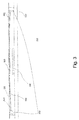
- the vibration apparatus 210 consists of a piezo beam 310, a permanent magnet 320 and an electro magnet 330.
- the clamped-clamped beam 310 is slightly curved.
- the permanent magnet 320 is fixed on bottom surface 350 of the piezo arch 310.
- Top surface 360 of the piezo arch 310 contacts with the touch screen 120.
- the vibration apparatus 210 is actuated by piezo electrical effect.
- the piezo arch 310 is in the first stable position 410 and it does not need energy for this.
- the piezo arch 310 is actuated by harmonic electrical current, therefore the haptic feedback functions are provided on the touch screen 120 for users.
- this Figure shows the first mode. That means an oscillation of the oscillation element 310 is causable by an application of an electric current to the oscillation element 310, wherein the oscillations of the oscillation element 310 cause the touch screen 120 at least locally vibrating for outputting signals via the vibrations to a user touching that screen 120.
- the magnetic actuator 330 generates a repulsive field for causing a contact between the oscillation element 310 and the touch screen 120.
- the oscillation element 310 is preferably pressed against the touch screen 120 by means of a magnetic field.
- the magnetic actuator 330 is preferably arranged on the oscillation element 310 or (as shown) spaced apart from the oscillation element 310.
- a further magnetic element 320 which is preferably a permanent magnet, is attached or arranged at or as part of the oscillation element. It is alternatively also conceivable that the oscillation element 310 has at least partially properties of a permanent magnet.
- the piezo arch 310 vibrates between two stable states for requirement of large amplitude oscillations.
- the bistable structure, the arch 310 has advantages such as working in large strokes and less power consumption.
- the repulsive magnetic force 450 is applied to the arch 310.
- the magnetic force 450 applies to the arch while vibrating between its two stable states. It makes easy that the arch returns second stable state to first stable state, therefore the magnetic force prevents to the arch 310 from instability in large strokes.
- the mass of the magnet 320 fixed on the arch 310 decreases resonance frequency of the arch 310; therefore consume of the activation energy of the system decreases.
- a rigidly fixed oscillation element 210 that has a bow respectively arc-shape in the stable states, needs to travel through a wave shape by switching the stable states.
- Figure 5 without request of haptic feedback applications, the arch 310 is in the first stable state 410.
- the attractive magnetic force 510 is applied to the arch 310.
- the magnetic force 510 decreases resonance frequency of the arch 310 by decreasing rigidity of it. Therefore, resonance frequency of the arch matches frequency of device motions and thus more energy can be harvested.
- Figure 5 shows a situation representing the second mode.
- a screen device 210 in particular for use in smart devices, is described, wherein the screen device 210 preferably at least comprises a touch screen 120, an oscillation element 310 at least temporarily coupled to the touch screen 120, wherein the touch screen 120 overlays the oscillating element 310, a control unit operating the oscillation element 310 in at least two different modes, wherein in a first mode an oscillation of the oscillation element 310 is causable by an application of an electric current to the oscillation element 310, wherein the oscillations of the oscillation element 310 cause the touch screen 120 at least locally vibrating for outputting signals via the vibrations to a user touching that screen 120, and wherein in a second mode the touch screen 120 transfers ambient excitations to the oscillation element 310, wherein those excitations are transformed by means of the oscillation element 310 into electric energy.
- the vibration apparatus preferably consists of a piezoelectric arch, a magnet fixed on the piezoelectric arch, a touch screen and an electro-magnet or another permanent magnet.
- the arch is actuated by inverse piezoelectric effect and thus haptic feedback functions are provided on the touch screen for users.
- the bistable nature the arch can be worked in large strokes compared to straight and monostable structures. Additional stationary permanent magnet or electro-magnet is optimizing strokes by changing overall natural frequency of the system.
- the vibration apparatus can be worked as an energy harvester in direct piezoelectric effect. Consequently, the vibration apparatus provides haptic feedback functions if requested by users. It harvests energy, if not requested of haptic feedback functions as well.
- the piezoelectric beam can be used to provide various and controllable vibration functions for users.
- the haptic feedback functions are provided by inverse piezoelectric effect of the arch.
- the arch harvests energy while oscillating from device motions.
Landscapes
- Engineering & Computer Science (AREA)
- Theoretical Computer Science (AREA)
- General Engineering & Computer Science (AREA)
- Physics & Mathematics (AREA)
- General Physics & Mathematics (AREA)
- Human Computer Interaction (AREA)
- Computer Hardware Design (AREA)
- Power Engineering (AREA)
- User Interface Of Digital Computer (AREA)
- Apparatuses For Generation Of Mechanical Vibrations (AREA)
- Control Of Indicators Other Than Cathode Ray Tubes (AREA)
Abstract

Description
- The present invention refers to a screen device according to claim 1, a smart device according to claim 11, a method for selective generation of haptic signals or electric energy by means of an oscillation element coupled to a touch screen according to claim 12 and a computer program product according to claim 15.
- Vibration systems provide vibrational alert and haptic feedback functions in portable electronic devices. Currently, vibration motors provide vibration for electronic devices; however, they have some disadvantages such as high-energy consumption and poor temporal resolution of vibration.
- It is therefore the object of the present invention to provide a screen device, a smart device, a method and a computer program product that provides an improved energy distribution. It is a further object of the present invention to provide a screen device, a smart device, a method and a computer program product that improves haptic signal output for a user.
- The before mentioned problems and objects are solved by a screen device according to claim 1. The screen device according to claim 1 preferably at least comprises a touch screen. It is further preferred that the screen device comprises at least one oscillation element. The oscillation element is preferably at least temporarily coupled to the touch screen. The touch screen preferably overlays the oscillating element. Furthermore, a control unit for operating the oscillation element in at least two different modes is preferably provided, wherein in a first mode an oscillation of the oscillation element is causable by an application of an electric current to the oscillation element, wherein the oscillations of the oscillation element cause the touch screen at least locally vibrating for outputting signals via the vibrations to a human being or user touching that screen, and wherein in a second mode the touch screen transfers ambient excitations to the oscillation element, wherein those excitations are transformed by means of the oscillation element into electric energy.
- Thus, this invention relates to a screen device respectively a vibration apparatus that provides haptic feedback functions for electronic devices and harvests energy from device motions, in particular from ambient excitations, like oscillations caused by acoustic waves. Therefore, the present invention provides an energy optimized solution which also requires less space compared with vibration motors since the components of the screen device are used for at least two different functions respectively effects.
- Advantageous embodiments may be configured according to any claim and/or the following specification parts.
- A magnetic actuator is provided according to a further preferred embodiment of the invention. According to the further embodiment the oscillating element overlays the magnetic actuator, wherein the magnetic actuator is operated in dependency of the different modes and wherein the oscillation element is deflectable by means of the magnetic actuator. Preferably at least one mechanical property of the oscillation element is affectable by the magnetic field caused by the magnetic actuator.
- According to a further preferred embodiment of the present invention the magnetic actuator is configured to apply repulsive forces to the oscillation element in the first mode for pressing the oscillation element against the touch screen. This embodiment is beneficial since oscillations caused by the oscillation element are in a stronger manner transferable to the touch screen the closer the oscillation element and the touch screen are arranged.
- The magnetic actuator is configured to apply attractive forces to the oscillation element in the second mode for manipulating of the natural frequency of the oscillation element according to a further preferred embodiment of the present invention. This embodiment is beneficial, since the oscillation element can be excited by different excitations, in particular acoustic waves, in particular of different sources and with different properties. Preferably a sensor unit is provided to detect the present potential excitation sources. The magnetic field caused by the magnetic actuator is preferably modified to match with the detected excitation sources. The modification of the magnetic actuator is preferably caused by the control unit based on values generated by the sensor unit as a result of the detection of the potential excitation sources.
- According to a further preferred embodiment of the present invention the magnetic actuator is configured to switch from the application of attractive forces to repulsive forces for modifying, in particular limiting, the oscillations of the oscillation element. This embodiment is beneficial since defects caused by intense oscillation can be avoided. The oscillations are preferably detected or supervised by means of an oscillation sensor unit. The oscillation sensor unit preferably outputs values based on the detected properties and the control unit preferably evaluates those values. Preferably, the control unit causes a modification of the magnetic field based on the measured respectively detected values.
- The oscillation element preferably consists of at least one piezo electric element or the oscillation element is preferably coupled to at least one piezo electric element or the oscillation element preferably comprises at least one piezo electric element. The oscillation element respectively the arch is preferably actuated by an AC electrical current for haptic feedback applications.
- According to a further preferred embodiment of the present invention the oscillation element is arc-shaped and arranged in such a manner that the oscillation element is bendable between a first arc-shaped stable configuration and a second arc-shaped stable configuration, wherein the oscillation element comprises a first surface section and second surface section, wherein the first surface section and the second surface section form surface sections of opposite sides of the oscillation element, wherein the first surface is the outer surface in the first arc-shaped stable configuration and wherein the second surface is the outer surface in the second arc-shaped stable configuration. Due to the bistable structure, the arch needs less power only during transition between two states, it does not need to hold it down in either stable states. Therefore, the arch works in larger strokes and consumes less power than straight or monostable structures. The repulsive magnetic force is applied to the arch to prevent from instability of it; therefore, the arch can be worked in large strokes safely.
- The oscillation element is preferably an arc-shaped piezo electric element coupled, in particular fixed or secured, with at least two socket elements according to a further preferred embodiment of the present invention. The radius of the arc-shape is preferably larger than 2 mm, in particular larger than 5 mm or larger than 10 mm or larger than 20 mm or larger than 50 mm or larger than 100 mm or larger than 150 mm. Thus, the oscillation element respectively arc-shaped element in the present screen device respectively vibration apparatus is preferably worked respectively operated by direct/inverse piezoelectric effect. In inverse piezoelectric effect, the oscillation element respectively arch provides haptic feedback functions on the touch screen. In direct piezoelectric effect, the oscillation element respectively arch harvests energy from device motions. The piezo beam respectively the oscillation element is curved in the vibration apparatus, therefore the curved beam can be worked in larger strokes and consumes less energy than a straight beam.
- According to a further preferred embodiment of the present invention a further magnetic element is provided. The further magnetic element is preferably coupled with the oscillation element. The magnetic actuator is preferably coupled with a component overlaid by the oscillation element. Alternatively the further magnetic element is coupled with a component overlaid by the oscillation element and wherein the magnetic actuator is coupled with the oscillation element.
- The magnet actuator is preferably designed as an electro magnet and/or the magnet element is preferably designed as an electro magnet, wherein the electro magnet is preferably operated in dependency of the oscillation element and/or wherein the electro magnet is preferably controlled by the control unit. The polarity of the magnet respectively magnet element fixed on the oscillation element respectively arch is preferably permanent, while polarity of the electro magnet placed away from the oscillation element preferably arch can be preferably changed. The magnetic force can be changed as repulsive or attractive with respect to polarization of the electro magnet. The repulsive force is applied on the arch for request of haptic feedback applications, whereas the attractive force is applied to the arch without request of haptic feedback applications.
- The present invention further refers to a smart device, in particular a smart phone, tablet PC or smart watch. The smart device of the present invention at least has one screen device according to any of claims 1 to 10 and/or a screen device described in this specification.
- Thus, the vibration apparatus respectively screen device respectively smart device preferably consists of or comprises an oscillation element, in particular a clamped-clamped piezoelectric arch, a magnetic element, in particular a magnet fixed on the arch, and a magnetic actuator, in particular an electro magnet placed away from the arch. The oscillation element respectively arch is preferably placed under the touch screen, in particular contacting the touch screen, in particular at least temporarily.
- The present invention further refers to a method for selective generation of haptic signals or electric energy by means of an oscillation element coupled to a touch screen. The method according to the invention preferably comprises at least the steps: Providing a touch screen, an oscillation element at least temporarily coupled to the touch screen, wherein the touch screen overlays the oscillating element and a control unit for operating the oscillation element in at least two different modes. Executing a selection step, wherein a selection between a first mode and a second mode takes place, wherein in the first mode an oscillation of the oscillation element is causable by an application of an electric current to the oscillation element, wherein the oscillations of the oscillation element cause the touch screen at least locally vibrating for outputting signals via the vibrations to a user touching that screen, and wherein in a second mode the touch screen transfers ambient excitations to the oscillation element, wherein those excitations are transformed by means of the oscillation element into electric energy. Executing the selected mode. According to a further preferred embodiment of the present invention the method further comprises the step of detecting or estimating a contact between the touch screen and a being, wherein the control unit selects the first mode in case a contact is detected or estimated, wherein the detection of a contact between the being, in particular a human, and the touch screen is detected by a sensor means, in particular a pressure sensor means.
- The oscillation element is according to a further preferred embodiment of the present invention preferably an arc-shaped piezo electric element coupled, in particular fixed or secured, with at least two socket elements, wherein the radius of the arc-shape is larger than 2 mm, in particular larger than 5 mm or larger than 10 mm or larger than 20 mm or larger than 50 mm, and the oscillation element is bendable between a first arc-shaped stable configuration and a second arc-shaped stable configuration, wherein the oscillation element comprises a first surface section and second surface section, wherein the first surface section and the second surface section form surface sections of opposite sides of the oscillation element, wherein the first surface is the outer surface in the first arc-shaped stable configuration and wherein the second surface is the outer surface in the second arc-shaped stable configuration, wherein the first mode is a signal outputting mode, wherein the control unit causes in the signal outputting mode energy supply to the piezo electric element in dependency of a detected or estimated contacting of the touchscreen and wherein the second mode is an energy harvesting mode, wherein the control unit causes an actuation of the magnetic actuator to cause a deflection of the oscillating element to hold the oscillation element in an instable state between the first stable configuration and the second stable configuration. Electrical energy is preferably harvested by oscillation of the oscillation element respectively the arch in inverse piezo electrical effect without request of haptic feedback functions. The attractive magnetic force is applied to the oscillation element respectively the arch. The natural frequency of the oscillation element respectively the arch decreases by the attractive force that decreases rigidity of the arch. Therefore, the vibration system in this invention can harvest energy from low-level device motions.
- The repulsive force between permanent and electro magnets prevents the instability of vibrating arch in large strokes for haptic feedback applications.
- The attractive force between permanent and electro magnets decreases the rigidity of arch it is easier to ensure matching between the resonant frequency of the harvester and the ambient vibration frequency. Therefore, the vibration system harvests more energy.
- The present invention further refers to a computer program product or system for executing one or more than one of the herein described methods.
- Further benefits, goals and features of the present invention will be described by the following specification of the attached figures, in which exemplarily components of the invention are illustrated. Components of the devices and methods according to the inventions, which match at least essentially with respect to their function can be marked with the same reference sign, wherein such components do not have to be marked or described in all figures.
- In the following the invention is just exemplarily described with respect to the attached figures.
-
- Fig. 1
- shows an isometric view of a haptic feedback apparatus in accordance with one exemplary embodiment of the present invention;
- Fig. 2a
- shows a placement of the vibration apparatus respectively the screen device in an electronic device;
- Fig. 2b
- shows a schematic side view of the inventive device shown in
Figure 2a . - Fig. 3
- shows a view of the vibration apparatus placed in the portable electronic device;
- Fig. 4a
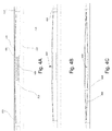
- shows a view of the screen device according to the invention for haptic feedback applications;
- Fig. 4b
- shows a mode wherein the oscillation unit respectively piezo arch is vibrates in small strokes
- Fig. 4c
- indicates an oscillation of the oscillation element in large strokes;
- Fig. 5
- shows how the screen device is can be operated without request of haptic feedback applications, in particular while energy harvesting.
- In this section, the invention is further explained in detail.
- In
Figure 1 , thehaptic feedback apparatus 100 is shown. Thehaptic feedback apparatus 100 consists of ahousing 110, atouch screen 120 and avibration apparatus 210. Thehaptic feedback apparatus 100 is assembled in a tablet PC. Thehaptic feedback apparatus 100 can be applied in other electronic devices, such as mobile phones, notebook computers and portable game devices. As shown inFig. 2A ,multiple screen devices 210 can be provided for one end-user device 100, wherein preferably multiple or all screen devices are preferably equipped with a section of thesame touch screen 120. In case ofmultiple screen devices 210 different shapes of thescreen devices 210 are possible. At least one or exactly onescreen device 210 respectively device with the arrangement of theoscillation element 310 according to the invention is present, wherein at least two or more than two, in particular 5 or more than 5 or up to 5, 8 or more than 8 or up to 8, 10 or more than 10 or up to 10, 15 or more than 15 or up to 15, 20 or more than 20 or up to 20, 25 or more than 25 or up to 25, 50 or more than 50 or up to 50 of such devices can be provided, in particular incorporated in an end-user device respectivelyfeedback apparatus 100. - A schematic side view of the
apparatus 100 ofFig. 2A is shown inFig. 2B . Thescreen devices 210 are connected to one ormore accumulator unit 220 by means of aconnection 230 respectively wire or printed circuit board. Energy harvested by thescreen device 210 is thus conductable by means of thatconnection 230 to theaccumulator unit 220. Theindividual screen devices 210 are individually or by means of a data bus directly or indirectly connected to acontrol unit 250, in particular a processor unit. Thecontrol unit 250 preferably determines the mode in question and causes the components to operate as desired in those modes. E.g. in case the first mode is determined or selected an electric current is conducted, in particular from theaccumulator unit 220, to at least or to exactly onescreen device 210. The electric current causes theoscillation element 310 of the at least onerespective screen device 210 to oscillate and thus to vibrate thetouch screen 120. Hereby preferably a detection or estimation of a contact between a being, in particular a human, in particular a fingertip of a human, takes place. Such a detection or estimation is preferably carried out by means of one ormore sensor units 240, in particular pressure sensor units. The outputted signal if thesensor unit 240 respectively sensor units is preferably interpreted by thecontrol unit 250 which then selects the required mode. It is alternatively conceivable that one ormore screen devices 210 are operated as sensor unit. In case thescreen devices 210 are operated in a second mode, in particular an energy harvesting mode, any contact by a user causes a significant deflection of theoscillation element 310 and therefore an interruption of the energy harvesting excitation. It is thus alternatively or additionally possible that thecontrol unit 250 interprets the signal indicating such an interruption as mode changing event. - The
vibration apparatus 210 is aligned under thetouch screen 120 inFigure 2A . Placement of them 210 can be changed to provide for various of haptic feedback functions. - In
Figure 3 , thevibration apparatus 210 placed under thetouch screen 120. Thevibration apparatus 210 consists of apiezo beam 310, apermanent magnet 320 and anelectro magnet 330. The clamped-clampedbeam 310 is slightly curved. Thepermanent magnet 320 is fixed onbottom surface 350 of thepiezo arch 310.Top surface 360 of thepiezo arch 310 contacts with thetouch screen 120. Thevibration apparatus 210 is actuated by piezo electrical effect. - In
Figure 4A , thepiezo arch 310 is in the firststable position 410 and it does not need energy for this. Thepiezo arch 310 is actuated by harmonic electrical current, therefore the haptic feedback functions are provided on thetouch screen 120 for users. Thus, this Figure shows the first mode. That means an oscillation of theoscillation element 310 is causable by an application of an electric current to theoscillation element 310, wherein the oscillations of theoscillation element 310 cause thetouch screen 120 at least locally vibrating for outputting signals via the vibrations to a user touching thatscreen 120. Themagnetic actuator 330 generates a repulsive field for causing a contact between theoscillation element 310 and thetouch screen 120. In the first mode theoscillation element 310 is preferably pressed against thetouch screen 120 by means of a magnetic field. Themagnetic actuator 330 is preferably arranged on theoscillation element 310 or (as shown) spaced apart from theoscillation element 310. Furthermore, preferably a furthermagnetic element 320, which is preferably a permanent magnet, is attached or arranged at or as part of the oscillation element. It is alternatively also conceivable that theoscillation element 310 has at least partially properties of a permanent magnet. - In
Figure 4B , thepiezo arch 310 vibrates around first stable situation for requirement of small amplitude oscillations. - In
Figure 4C , thepiezo arch 310 vibrates between two stable states for requirement of large amplitude oscillations. The bistable structure, the arch 310 has advantages such as working in large strokes and less power consumption. The repulsivemagnetic force 450 is applied to the arch 310. Themagnetic force 450 applies to the arch while vibrating between its two stable states. It makes easy that the arch returns second stable state to first stable state, therefore the magnetic force prevents to the arch 310 from instability in large strokes. The mass of themagnet 320 fixed on the arch 310 decreases resonance frequency of the arch 310; therefore consume of the activation energy of the system decreases. It can be understood fromFigure 4C that a rigidly fixedoscillation element 210, that has a bow respectively arc-shape in the stable states, needs to travel through a wave shape by switching the stable states. - In
Figure 5 , without request of haptic feedback applications, the arch 310 is in the firststable state 410. The attractivemagnetic force 510 is applied to the arch 310. Themagnetic force 510 decreases resonance frequency of the arch 310 by decreasing rigidity of it. Therefore, resonance frequency of the arch matches frequency of device motions and thus more energy can be harvested. Thus,Figure 5 shows a situation representing the second mode. - Thus, a
screen device 210, in particular for use in smart devices, is described, wherein thescreen device 210 preferably at least comprises atouch screen 120, anoscillation element 310 at least temporarily coupled to thetouch screen 120, wherein thetouch screen 120 overlays theoscillating element 310, a control unit operating theoscillation element 310 in at least two different modes, wherein in a first mode an oscillation of theoscillation element 310 is causable by an application of an electric current to theoscillation element 310, wherein the oscillations of theoscillation element 310 cause thetouch screen 120 at least locally vibrating for outputting signals via the vibrations to a user touching thatscreen 120, and wherein in a second mode thetouch screen 120 transfers ambient excitations to theoscillation element 310, wherein those excitations are transformed by means of theoscillation element 310 into electric energy. - Therefore, a new vibration apparatus respectively screen device has been developed to provide haptic feedback functions for portable electronic devices, in particular smart devices. The vibration apparatus preferably consists of a piezoelectric arch, a magnet fixed on the piezoelectric arch, a touch screen and an electro-magnet or another permanent magnet. The arch is actuated by inverse piezoelectric effect and thus haptic feedback functions are provided on the touch screen for users. The bistable nature, the arch can be worked in large strokes compared to straight and monostable structures. Additional stationary permanent magnet or electro-magnet is optimizing strokes by changing overall natural frequency of the system. In addition, the vibration apparatus can be worked as an energy harvester in direct piezoelectric effect. Consequently, the vibration apparatus provides haptic feedback functions if requested by users. It harvests energy, if not requested of haptic feedback functions as well.
- Thus, the piezoelectric beam can be used to provide various and controllable vibration functions for users. In this invention, the haptic feedback functions are provided by inverse piezoelectric effect of the arch. In direct piezoelectric effect, the arch harvests energy while oscillating from device motions.
-
- 100
- haptic feedback apparatus or screen device
- 110
- housing
- 120
- touch screen
- 210
- vibration apparatus or screen device
- 220
- accumulator
- 230
- connection / cable
- 240
- sensor means
- 250
- control unit / processor unit
- 310
- piezo beam or oscillation element
- 320
- permanent magnet or magnetic element
- 330
- electro magnet or magnetic actuator
- 340
- socket element
- 350
- bottom surface
- 360
- top surface
- 410
- first stable position
- 420
- direction of transferring oscillations
- 430
- second stable position
- 440
- maximum displacement
- 450
- repulsive magnetic force
- 510
- attractive magnetic force
Claims (15)
- Screen device (210), in particular for use in smart devices,
at least comprising:- a touch screen (120),- an oscillation element (310) at least temporarily coupled to the touch screen (120), wherein the touch screen (120) overlays the oscillating element (310),- a control unit for operating the oscillation element (310) in at least two different modeswherein in a first mode an oscillation of the oscillation element (310) is causable by an application of an electric current to the oscillation element (310), wherein the oscillations of the oscillation element (310) cause the touch screen (120) at least locally to vibrate for outputting signals via the vibrations to a user touching that screen (120),
and
wherein in a second mode the touch screen (120) transfers ambient excitations to the oscillation element (310),
wherein those excitations are transformed by means of the oscillation element (310) into electric energy. - Screen device according to claim 1,
characterized in that
a magnetic actuator (330) is provided,
wherein the oscillating element (310) overlays the magnetic actuator (330),
wherein the magnetic actuator (330) is operated in dependency of the different modes,
wherein the oscillation element (310) is deflectable by means of the magnetic actuator (330). - Screen device according to claim 2,
characterized in that
the magnetic actuator (330) is configured to apply repulsive forces to the oscillation element (310) in the first mode for pressing the oscillation element (310) against the touch screen (120). - Screen device according to claim 2 or 3,
characterized in that
the magnetic actuator (330) is configured to apply attractive forces to the oscillation element (310) in the second mode for manipulating of the natural frequency of the oscillation element (310). - Screen device according to claim 4,
characterized in that
the magnetic actuator (330) is configured to switch from the application of attractive forces to repulsive forces for modifying, in particular limiting, the oscillations of the oscillation element (310). - Screen device according to any of the proceeding claims,
characterized in that
the oscillation element (310) consists of at least one piezo electric element or the oscillation element (310) is coupled to at least one piezo electric element or the oscillation element (310) comprises at least one piezo electric element. - Screen device according to any of the proceeding claims,
characterized in that
the oscillation element (310) is arc-shaped and arranged in such a manner that the oscillation element (310) is bendable between a first arc-shaped stable configuration and a second arc-shaped stable configuration, wherein the oscillation element (310) comprises a first surface section (360) and second surface section (350), wherein the first surface section (360) and the second surface section (350) form surface sections of opposite sides of the oscillation element (310), wherein the first surface section (360) is the outer surface in the first arc-shaped stable configuration and wherein the second surface section (350) is the outer surface in the second arc-shaped stable configuration. - Screen device according to any of the proceeding claims,
characterized in that
the oscillation element (310) is an arc-shaped piezo electric element coupled, in particular fixed or secured, with at least two socket elements, wherein the radius of the arc-shape is larger than 2 mm, in particular larger than 5 mm or larger than 10 mm or larger than 20 mm or larger than 50 mm. - Screen device according to any of the preceding claims,
characterized in that
a further magnetic element (320) is provided,
wherein the further magnetic element (320) is coupled with the oscillation element (310) and wherein the magnetic actuator (330) is coupled with a component overlaid by the oscillation element (310) or
wherein the further magnetic element (320) is coupled with a component overlaid by the oscillation element (310) and wherein the magnetic actuator (330) is coupled with the oscillation element (310). - Screen device according to any of the preceding claims 2 to 9,
characterized in that
the magnet actuator (330) is an electro magnet and/or the magnet element (320) is an electro magnet,
wherein the electro magnet is operated in dependency of the oscillation element (310) and/or
wherein electro magnet is controlled by the control unit. - Smart device, in particular smart phone, tablet PC or smart watch, at least having one screen device (210) according to any of claims 1 to 10.
- Method for selective generation of haptic signals or electric energy by means of an oscillation element (310) coupled to a touch screen (120),
at least comprising the steps:Providinga touch screen (120),an oscillation element (310),wherein the oscillation element (310) is at least temporarily coupled to the touch screen (120),
wherein the touch screen (120) overlays the oscillating element (310), and
a control unit for operating the oscillation element (310) in at least two different modes,Executing a selection step,wherein a selection between a first mode and a second mode takes place,
wherein in the first mode an oscillation of the oscillation element (310) is causable by an application of an electric current to the oscillation element (310), wherein the oscillations of the oscillation element (310) cause the touch screen (120) at least locally vibrating for outputting signals via the vibrations to a user touching that touch screen (120),
and
wherein in a second mode the touch screen (120) transfers ambient excitations to the oscillation element (310), wherein those excitations are transformed by means of the oscillation element (310) into electric energy,
Executing the selected mode. - Method according to claim 12,
characterized in that
the method further comprises the step of detecting or estimating a contact between the touch screen (120) and a user, wherein the control unit selects the first mode in case a contact is detected or estimated, wherein the detection of a contact between the user and the touch screen (120) is detected by a sensor means, in particular a pressure sensor means. - Method according to any of the preceding methods,
characterized in that,
the oscillation element (310) is an arc-shaped piezo electric element coupled, in particular fixed or secured, with at least two socket elements (340), wherein the radius of the arc-shape is larger than 2 mm, in particular larger than 5 mm or larger than 10 mm or larger than 20 mm or larger than 50 mm, and
the oscillation element (310) is bendable between a first arc-shaped stable configuration and a second arc-shaped stable configuration, wherein the oscillation element (310) comprises a first surface section (360) and second surface section (350), wherein the first surface section (360) and the second surface section (350) form surface sections of opposite sides of the oscillation element (310), wherein the first surface section (360) is the outer surface in the first arc-shaped stable configuration and wherein the second surface section (350) is the outer surface in the second arc-shaped stable configuration,
wherein the first mode is a signal outputting mode, wherein the control unit causes in the signal outputting mode energy supply to the piezo electric element in dependency of a detected or estimated contacting of the touchscreen (120),
and
wherein the second mode is an energy harvesting mode, wherein the control unit causes an actuation of the magnetic actuator (330) to cause a deflection of the oscillating element (310) to hold the oscillation element (310) in an instable state between the first stable configuration and the second stable configuration. - Computer program product or system for executing a method according to any of claims 12 to 14.
Priority Applications (2)
| Application Number | Priority Date | Filing Date | Title |
|---|---|---|---|
| EP16155906.7A EP3208688B1 (en) | 2016-02-16 | 2016-02-16 | Screen device for energy harvesting and signal output |
| TR2017/02049A TR201702049A2 (en) | 2016-02-16 | 2017-02-10 | Display device for energy harvesting and signal output. |
Applications Claiming Priority (1)
| Application Number | Priority Date | Filing Date | Title |
|---|---|---|---|
| EP16155906.7A EP3208688B1 (en) | 2016-02-16 | 2016-02-16 | Screen device for energy harvesting and signal output |
Publications (2)
| Publication Number | Publication Date |
|---|---|
| EP3208688A1 true EP3208688A1 (en) | 2017-08-23 |
| EP3208688B1 EP3208688B1 (en) | 2019-04-24 |
Family
ID=55456583
Family Applications (1)
| Application Number | Title | Priority Date | Filing Date |
|---|---|---|---|
| EP16155906.7A Active EP3208688B1 (en) | 2016-02-16 | 2016-02-16 | Screen device for energy harvesting and signal output |
Country Status (2)
| Country | Link |
|---|---|
| EP (1) | EP3208688B1 (en) |
| TR (1) | TR201702049A2 (en) |
Cited By (3)
| Publication number | Priority date | Publication date | Assignee | Title |
|---|---|---|---|---|
| DE102018112008A1 (en) * | 2018-05-18 | 2019-11-21 | Innogy Se | Mobile device |
| JP2019203755A (en) * | 2018-05-22 | 2019-11-28 | 京セラ株式会社 | Measurement device and control method therefor |
| WO2021121542A1 (en) * | 2019-12-16 | 2021-06-24 | Huawei Technologies Co., Ltd. | Multifunctional haptic actuator |
Citations (3)
| Publication number | Priority date | Publication date | Assignee | Title |
|---|---|---|---|---|
| US20130328447A1 (en) * | 2012-06-08 | 2013-12-12 | Samsung Electronics Co., Ltd. | Actuator using electro-active polymer and electronic device therewith |
| US20140240108A1 (en) * | 2013-02-25 | 2014-08-28 | Nokia Corporation | Method and Apparatus for a Flexible Housing |
| WO2015047309A1 (en) * | 2013-09-27 | 2015-04-02 | Pearl Capital Developments Llc | Vibration component that harvests energy for electronic devices |
-
2016
- 2016-02-16 EP EP16155906.7A patent/EP3208688B1/en active Active
-
2017
- 2017-02-10 TR TR2017/02049A patent/TR201702049A2/en unknown
Patent Citations (3)
| Publication number | Priority date | Publication date | Assignee | Title |
|---|---|---|---|---|
| US20130328447A1 (en) * | 2012-06-08 | 2013-12-12 | Samsung Electronics Co., Ltd. | Actuator using electro-active polymer and electronic device therewith |
| US20140240108A1 (en) * | 2013-02-25 | 2014-08-28 | Nokia Corporation | Method and Apparatus for a Flexible Housing |
| WO2015047309A1 (en) * | 2013-09-27 | 2015-04-02 | Pearl Capital Developments Llc | Vibration component that harvests energy for electronic devices |
Cited By (8)
| Publication number | Priority date | Publication date | Assignee | Title |
|---|---|---|---|---|
| DE102018112008A1 (en) * | 2018-05-18 | 2019-11-21 | Innogy Se | Mobile device |
| JP2019203755A (en) * | 2018-05-22 | 2019-11-28 | 京セラ株式会社 | Measurement device and control method therefor |
| WO2019225327A1 (en) * | 2018-05-22 | 2019-11-28 | 京セラ株式会社 | Measurement device and control method for measurement device |
| WO2021121542A1 (en) * | 2019-12-16 | 2021-06-24 | Huawei Technologies Co., Ltd. | Multifunctional haptic actuator |
| CN114072243A (en) * | 2019-12-16 | 2022-02-18 | 华为技术有限公司 | Multi-functional haptic actuator |
| EP4066369A1 (en) * | 2019-12-16 | 2022-10-05 | Huawei Technologies Co., Ltd. | Multifunctional haptic actuator |
| CN114072243B (en) * | 2019-12-16 | 2023-04-04 | 华为技术有限公司 | Multifunctional haptic actuator |
| US12124631B2 (en) | 2019-12-16 | 2024-10-22 | Huawei Technologies Co., Ltd. | Multifunctional haptic actuator |
Also Published As
| Publication number | Publication date |
|---|---|
| EP3208688B1 (en) | 2019-04-24 |
| TR201702049A2 (en) | 2017-09-21 |
Similar Documents
| Publication | Publication Date | Title |
|---|---|---|
| US8073501B2 (en) | Method and apparatus for providing haptic feedback to non-input locations | |
| JP4568498B2 (en) | Electronic devices and dynamic user interfaces | |
| US9829981B1 (en) | Haptic output device | |
| US10261585B2 (en) | Adjusting the level of acoustic and haptic output in haptic devices | |
| KR101016208B1 (en) | Mixed actuator using vibration generating means and electromagnetic force generating means, vibration haptic providing device using same, display device using same and control method thereof | |
| US10275030B2 (en) | Method and apparatus for providing haptic feedback to non-input locations | |
| US20160241119A1 (en) | Vibration Component that Harvests Energy for Electronic Devices | |
| JP5822022B2 (en) | Electronic device and drive control program | |
| KR20150039605A (en) | Protective case for mobile terminalproviding real time vibration feedback | |
| KR20140109292A (en) | Haptic device with linear resonant actuator | |
| JP2015121983A (en) | Tactile presentation device | |
| KR20110077637A (en) | Piezoelectric Actuator for Driving Haptic Devices | |
| KR20120013273A (en) | Piezoelectric Actuator for Driving Haptic Devices | |
| JP2021515941A (en) | Human computer interface system | |
| EP3208688B1 (en) | Screen device for energy harvesting and signal output | |
| JP5748980B2 (en) | Input device and input system | |
| US20150123913A1 (en) | Apparatus and method for producing lateral force on a touchscreen | |
| CN113227939A (en) | Using actuators as sensors for input | |
| JP2018200533A (en) | Tactile transmission device | |
| US8902176B2 (en) | Haptic feedback apparatus | |
| KR101278293B1 (en) | Traveling vibrotactile wave generation method for implementing traveling vibrotactile wave by sequentially driving multiple actuators changing actuators' driving frequency according to the velocity of virtual object and generating continuously varying area of vibrotactile position | |
| EP3889736A1 (en) | Electronic device | |
| CN103080875A (en) | Force-feedback device | |
| KR101285416B1 (en) | Traveling vibrotactile wave generation method for implementing traveling vibrotactile wave by sequentially driving multiple actuators changing actuators' driving frequency according to the velocity of virtual object | |
| JP2018200534A (en) | Tactile transmission device |
Legal Events
| Date | Code | Title | Description |
|---|---|---|---|
| PUAI | Public reference made under article 153(3) epc to a published international application that has entered the european phase |
Free format text: ORIGINAL CODE: 0009012 |
|
| STAA | Information on the status of an ep patent application or granted ep patent |
Free format text: STATUS: THE APPLICATION HAS BEEN PUBLISHED |
|
| AK | Designated contracting states |
Kind code of ref document: A1 Designated state(s): AL AT BE BG CH CY CZ DE DK EE ES FI FR GB GR HR HU IE IS IT LI LT LU LV MC MK MT NL NO PL PT RO RS SE SI SK SM TR |
|
| AX | Request for extension of the european patent |
Extension state: BA ME |
|
| STAA | Information on the status of an ep patent application or granted ep patent |
Free format text: STATUS: REQUEST FOR EXAMINATION WAS MADE |
|
| 17P | Request for examination filed |
Effective date: 20180223 |
|
| RBV | Designated contracting states (corrected) |
Designated state(s): AL AT BE BG CH CY CZ DE DK EE ES FI FR GB GR HR HU IE IS IT LI LT LU LV MC MK MT NL NO PL PT RO RS SE SI SK SM TR |
|
| STAA | Information on the status of an ep patent application or granted ep patent |
Free format text: STATUS: EXAMINATION IS IN PROGRESS |
|
| 17Q | First examination report despatched |
Effective date: 20180523 |
|
| GRAP | Despatch of communication of intention to grant a patent |
Free format text: ORIGINAL CODE: EPIDOSNIGR1 |
|
| STAA | Information on the status of an ep patent application or granted ep patent |
Free format text: STATUS: GRANT OF PATENT IS INTENDED |
|
| RIC1 | Information provided on ipc code assigned before grant |
Ipc: G06F 1/16 20060101ALI20181116BHEP Ipc: G06F 3/01 20060101AFI20181116BHEP Ipc: G06F 3/0354 20130101ALI20181116BHEP Ipc: G06F 3/041 20060101ALI20181116BHEP Ipc: G06F 1/32 20060101ALI20181116BHEP Ipc: G06F 1/26 20060101ALI20181116BHEP |
|
| INTG | Intention to grant announced |
Effective date: 20181204 |
|
| GRAS | Grant fee paid |
Free format text: ORIGINAL CODE: EPIDOSNIGR3 |
|
| GRAA | (expected) grant |
Free format text: ORIGINAL CODE: 0009210 |
|
| STAA | Information on the status of an ep patent application or granted ep patent |
Free format text: STATUS: THE PATENT HAS BEEN GRANTED |
|
| AK | Designated contracting states |
Kind code of ref document: B1 Designated state(s): AL AT BE BG CH CY CZ DE DK EE ES FI FR GB GR HR HU IE IS IT LI LT LU LV MC MK MT NL NO PL PT RO RS SE SI SK SM TR |
|
| REG | Reference to a national code |
Ref country code: GB Ref legal event code: FG4D |
|
| REG | Reference to a national code |
Ref country code: CH Ref legal event code: EP |
|
| REG | Reference to a national code |
Ref country code: DE Ref legal event code: R096 Ref document number: 602016012708 Country of ref document: DE |
|
| REG | Reference to a national code |
Ref country code: AT Ref legal event code: REF Ref document number: 1124893 Country of ref document: AT Kind code of ref document: T Effective date: 20190515 Ref country code: IE Ref legal event code: FG4D |
|
| REG | Reference to a national code |
Ref country code: NL Ref legal event code: MP Effective date: 20190424 |
|
| REG | Reference to a national code |
Ref country code: LT Ref legal event code: MG4D |
|
| PG25 | Lapsed in a contracting state [announced via postgrant information from national office to epo] |
Ref country code: NL Free format text: LAPSE BECAUSE OF FAILURE TO SUBMIT A TRANSLATION OF THE DESCRIPTION OR TO PAY THE FEE WITHIN THE PRESCRIBED TIME-LIMIT Effective date: 20190424 |
|
| PG25 | Lapsed in a contracting state [announced via postgrant information from national office to epo] |
Ref country code: PT Free format text: LAPSE BECAUSE OF FAILURE TO SUBMIT A TRANSLATION OF THE DESCRIPTION OR TO PAY THE FEE WITHIN THE PRESCRIBED TIME-LIMIT Effective date: 20190824 Ref country code: AL Free format text: LAPSE BECAUSE OF FAILURE TO SUBMIT A TRANSLATION OF THE DESCRIPTION OR TO PAY THE FEE WITHIN THE PRESCRIBED TIME-LIMIT Effective date: 20190424 Ref country code: SE Free format text: LAPSE BECAUSE OF FAILURE TO SUBMIT A TRANSLATION OF THE DESCRIPTION OR TO PAY THE FEE WITHIN THE PRESCRIBED TIME-LIMIT Effective date: 20190424 Ref country code: HR Free format text: LAPSE BECAUSE OF FAILURE TO SUBMIT A TRANSLATION OF THE DESCRIPTION OR TO PAY THE FEE WITHIN THE PRESCRIBED TIME-LIMIT Effective date: 20190424 Ref country code: NO Free format text: LAPSE BECAUSE OF FAILURE TO SUBMIT A TRANSLATION OF THE DESCRIPTION OR TO PAY THE FEE WITHIN THE PRESCRIBED TIME-LIMIT Effective date: 20190724 Ref country code: FI Free format text: LAPSE BECAUSE OF FAILURE TO SUBMIT A TRANSLATION OF THE DESCRIPTION OR TO PAY THE FEE WITHIN THE PRESCRIBED TIME-LIMIT Effective date: 20190424 Ref country code: LT Free format text: LAPSE BECAUSE OF FAILURE TO SUBMIT A TRANSLATION OF THE DESCRIPTION OR TO PAY THE FEE WITHIN THE PRESCRIBED TIME-LIMIT Effective date: 20190424 |
|
| PG25 | Lapsed in a contracting state [announced via postgrant information from national office to epo] |
Ref country code: PL Free format text: LAPSE BECAUSE OF FAILURE TO SUBMIT A TRANSLATION OF THE DESCRIPTION OR TO PAY THE FEE WITHIN THE PRESCRIBED TIME-LIMIT Effective date: 20190424 Ref country code: LV Free format text: LAPSE BECAUSE OF FAILURE TO SUBMIT A TRANSLATION OF THE DESCRIPTION OR TO PAY THE FEE WITHIN THE PRESCRIBED TIME-LIMIT Effective date: 20190424 Ref country code: BG Free format text: LAPSE BECAUSE OF FAILURE TO SUBMIT A TRANSLATION OF THE DESCRIPTION OR TO PAY THE FEE WITHIN THE PRESCRIBED TIME-LIMIT Effective date: 20190724 Ref country code: RS Free format text: LAPSE BECAUSE OF FAILURE TO SUBMIT A TRANSLATION OF THE DESCRIPTION OR TO PAY THE FEE WITHIN THE PRESCRIBED TIME-LIMIT Effective date: 20190424 Ref country code: GR Free format text: LAPSE BECAUSE OF FAILURE TO SUBMIT A TRANSLATION OF THE DESCRIPTION OR TO PAY THE FEE WITHIN THE PRESCRIBED TIME-LIMIT Effective date: 20190725 |
|
| REG | Reference to a national code |
Ref country code: AT Ref legal event code: MK05 Ref document number: 1124893 Country of ref document: AT Kind code of ref document: T Effective date: 20190424 |
|
| PG25 | Lapsed in a contracting state [announced via postgrant information from national office to epo] |
Ref country code: IS Free format text: LAPSE BECAUSE OF FAILURE TO SUBMIT A TRANSLATION OF THE DESCRIPTION OR TO PAY THE FEE WITHIN THE PRESCRIBED TIME-LIMIT Effective date: 20190824 |
|
| REG | Reference to a national code |
Ref country code: DE Ref legal event code: R097 Ref document number: 602016012708 Country of ref document: DE |
|
| PG25 | Lapsed in a contracting state [announced via postgrant information from national office to epo] |
Ref country code: AT Free format text: LAPSE BECAUSE OF FAILURE TO SUBMIT A TRANSLATION OF THE DESCRIPTION OR TO PAY THE FEE WITHIN THE PRESCRIBED TIME-LIMIT Effective date: 20190424 Ref country code: DK Free format text: LAPSE BECAUSE OF FAILURE TO SUBMIT A TRANSLATION OF THE DESCRIPTION OR TO PAY THE FEE WITHIN THE PRESCRIBED TIME-LIMIT Effective date: 20190424 Ref country code: SK Free format text: LAPSE BECAUSE OF FAILURE TO SUBMIT A TRANSLATION OF THE DESCRIPTION OR TO PAY THE FEE WITHIN THE PRESCRIBED TIME-LIMIT Effective date: 20190424 Ref country code: EE Free format text: LAPSE BECAUSE OF FAILURE TO SUBMIT A TRANSLATION OF THE DESCRIPTION OR TO PAY THE FEE WITHIN THE PRESCRIBED TIME-LIMIT Effective date: 20190424 Ref country code: RO Free format text: LAPSE BECAUSE OF FAILURE TO SUBMIT A TRANSLATION OF THE DESCRIPTION OR TO PAY THE FEE WITHIN THE PRESCRIBED TIME-LIMIT Effective date: 20190424 Ref country code: CZ Free format text: LAPSE BECAUSE OF FAILURE TO SUBMIT A TRANSLATION OF THE DESCRIPTION OR TO PAY THE FEE WITHIN THE PRESCRIBED TIME-LIMIT Effective date: 20190424 |
|
| PG25 | Lapsed in a contracting state [announced via postgrant information from national office to epo] |
Ref country code: SM Free format text: LAPSE BECAUSE OF FAILURE TO SUBMIT A TRANSLATION OF THE DESCRIPTION OR TO PAY THE FEE WITHIN THE PRESCRIBED TIME-LIMIT Effective date: 20190424 Ref country code: IT Free format text: LAPSE BECAUSE OF FAILURE TO SUBMIT A TRANSLATION OF THE DESCRIPTION OR TO PAY THE FEE WITHIN THE PRESCRIBED TIME-LIMIT Effective date: 20190424 |
|
| PLBE | No opposition filed within time limit |
Free format text: ORIGINAL CODE: 0009261 |
|
| STAA | Information on the status of an ep patent application or granted ep patent |
Free format text: STATUS: NO OPPOSITION FILED WITHIN TIME LIMIT |
|
| 26N | No opposition filed |
Effective date: 20200127 |
|
| PG25 | Lapsed in a contracting state [announced via postgrant information from national office to epo] |
Ref country code: SI Free format text: LAPSE BECAUSE OF FAILURE TO SUBMIT A TRANSLATION OF THE DESCRIPTION OR TO PAY THE FEE WITHIN THE PRESCRIBED TIME-LIMIT Effective date: 20190424 |
|
| REG | Reference to a national code |
Ref country code: CH Ref legal event code: PL |
|
| REG | Reference to a national code |
Ref country code: BE Ref legal event code: MM Effective date: 20200229 |
|
| PG25 | Lapsed in a contracting state [announced via postgrant information from national office to epo] |
Ref country code: LU Free format text: LAPSE BECAUSE OF NON-PAYMENT OF DUE FEES Effective date: 20200216 Ref country code: MC Free format text: LAPSE BECAUSE OF FAILURE TO SUBMIT A TRANSLATION OF THE DESCRIPTION OR TO PAY THE FEE WITHIN THE PRESCRIBED TIME-LIMIT Effective date: 20190424 Ref country code: ES Free format text: LAPSE BECAUSE OF FAILURE TO SUBMIT A TRANSLATION OF THE DESCRIPTION OR TO PAY THE FEE WITHIN THE PRESCRIBED TIME-LIMIT Effective date: 20190424 |
|
| PG25 | Lapsed in a contracting state [announced via postgrant information from national office to epo] |
Ref country code: CH Free format text: LAPSE BECAUSE OF NON-PAYMENT OF DUE FEES Effective date: 20200229 Ref country code: LI Free format text: LAPSE BECAUSE OF NON-PAYMENT OF DUE FEES Effective date: 20200229 |
|
| PG25 | Lapsed in a contracting state [announced via postgrant information from national office to epo] |
Ref country code: IE Free format text: LAPSE BECAUSE OF NON-PAYMENT OF DUE FEES Effective date: 20200216 Ref country code: FR Free format text: LAPSE BECAUSE OF NON-PAYMENT OF DUE FEES Effective date: 20200229 |
|
| PG25 | Lapsed in a contracting state [announced via postgrant information from national office to epo] |
Ref country code: BE Free format text: LAPSE BECAUSE OF NON-PAYMENT OF DUE FEES Effective date: 20200229 |
|
| PG25 | Lapsed in a contracting state [announced via postgrant information from national office to epo] |
Ref country code: MT Free format text: LAPSE BECAUSE OF FAILURE TO SUBMIT A TRANSLATION OF THE DESCRIPTION OR TO PAY THE FEE WITHIN THE PRESCRIBED TIME-LIMIT Effective date: 20190424 Ref country code: CY Free format text: LAPSE BECAUSE OF FAILURE TO SUBMIT A TRANSLATION OF THE DESCRIPTION OR TO PAY THE FEE WITHIN THE PRESCRIBED TIME-LIMIT Effective date: 20190424 |
|
| PG25 | Lapsed in a contracting state [announced via postgrant information from national office to epo] |
Ref country code: MK Free format text: LAPSE BECAUSE OF FAILURE TO SUBMIT A TRANSLATION OF THE DESCRIPTION OR TO PAY THE FEE WITHIN THE PRESCRIBED TIME-LIMIT Effective date: 20190424 |
|
| PGFP | Annual fee paid to national office [announced via postgrant information from national office to epo] |
Ref country code: DE Payment date: 20240219 Year of fee payment: 9 Ref country code: GB Payment date: 20240219 Year of fee payment: 9 |
|
| REG | Reference to a national code |
Ref country code: DE Ref legal event code: R119 Ref document number: 602016012708 Country of ref document: DE |
|
| GBPC | Gb: european patent ceased through non-payment of renewal fee |
Effective date: 20250216 |
|
| PG25 | Lapsed in a contracting state [announced via postgrant information from national office to epo] |
Ref country code: DE Free format text: LAPSE BECAUSE OF NON-PAYMENT OF DUE FEES Effective date: 20250902 |
|
| PG25 | Lapsed in a contracting state [announced via postgrant information from national office to epo] |
Ref country code: GB Free format text: LAPSE BECAUSE OF NON-PAYMENT OF DUE FEES Effective date: 20250216 |
|
| PGFP | Annual fee paid to national office [announced via postgrant information from national office to epo] |
Ref country code: TR Payment date: 20260213 Year of fee payment: 11 |