EP3208424A1 - Gas turbine engine component having vascular engineered lattice structure - Google Patents
Gas turbine engine component having vascular engineered lattice structure Download PDFInfo
- Publication number
- EP3208424A1 EP3208424A1 EP17156353.9A EP17156353A EP3208424A1 EP 3208424 A1 EP3208424 A1 EP 3208424A1 EP 17156353 A EP17156353 A EP 17156353A EP 3208424 A1 EP3208424 A1 EP 3208424A1
- Authority
- EP
- European Patent Office
- Prior art keywords
- platform
- lattice structure
- vascular engineered
- engineered lattice
- flowpath
- Prior art date
- Legal status (The legal status is an assumption and is not a legal conclusion. Google has not performed a legal analysis and makes no representation as to the accuracy of the status listed.)
- Withdrawn
Links
Images




Classifications
-
- F—MECHANICAL ENGINEERING; LIGHTING; HEATING; WEAPONS; BLASTING
- F01—MACHINES OR ENGINES IN GENERAL; ENGINE PLANTS IN GENERAL; STEAM ENGINES
- F01D—NON-POSITIVE DISPLACEMENT MACHINES OR ENGINES, e.g. STEAM TURBINES
- F01D5/00—Blades; Blade-carrying members; Heating, heat-insulating, cooling or antivibration means on the blades or the members
- F01D5/12—Blades
- F01D5/14—Form or construction
- F01D5/18—Hollow blades, i.e. blades with cooling or heating channels or cavities; Heating, heat-insulating or cooling means on blades
- F01D5/187—Convection cooling
-
- B—PERFORMING OPERATIONS; TRANSPORTING
- B22—CASTING; POWDER METALLURGY
- B22F—WORKING METALLIC POWDER; MANUFACTURE OF ARTICLES FROM METALLIC POWDER; MAKING METALLIC POWDER; APPARATUS OR DEVICES SPECIALLY ADAPTED FOR METALLIC POWDER
- B22F5/00—Manufacture of workpieces or articles from metallic powder characterised by the special shape of the product
- B22F5/009—Manufacture of workpieces or articles from metallic powder characterised by the special shape of the product of turbine components other than turbine blades
-
- B—PERFORMING OPERATIONS; TRANSPORTING
- B33—ADDITIVE MANUFACTURING TECHNOLOGY
- B33Y—ADDITIVE MANUFACTURING, i.e. MANUFACTURING OF THREE-DIMENSIONAL [3D] OBJECTS BY ADDITIVE DEPOSITION, ADDITIVE AGGLOMERATION OR ADDITIVE LAYERING, e.g. BY 3D PRINTING, STEREOLITHOGRAPHY OR SELECTIVE LASER SINTERING
- B33Y80/00—Products made by additive manufacturing
-
- F—MECHANICAL ENGINEERING; LIGHTING; HEATING; WEAPONS; BLASTING
- F01—MACHINES OR ENGINES IN GENERAL; ENGINE PLANTS IN GENERAL; STEAM ENGINES
- F01D—NON-POSITIVE DISPLACEMENT MACHINES OR ENGINES, e.g. STEAM TURBINES
- F01D25/00—Component parts, details, or accessories, not provided for in, or of interest apart from, other groups
- F01D25/08—Cooling; Heating; Heat-insulation
- F01D25/12—Cooling
-
- F—MECHANICAL ENGINEERING; LIGHTING; HEATING; WEAPONS; BLASTING
- F01—MACHINES OR ENGINES IN GENERAL; ENGINE PLANTS IN GENERAL; STEAM ENGINES
- F01D—NON-POSITIVE DISPLACEMENT MACHINES OR ENGINES, e.g. STEAM TURBINES
- F01D5/00—Blades; Blade-carrying members; Heating, heat-insulating, cooling or antivibration means on the blades or the members
- F01D5/12—Blades
- F01D5/14—Form or construction
- F01D5/147—Construction, i.e. structural features, e.g. of weight-saving hollow blades
-
- F—MECHANICAL ENGINEERING; LIGHTING; HEATING; WEAPONS; BLASTING
- F01—MACHINES OR ENGINES IN GENERAL; ENGINE PLANTS IN GENERAL; STEAM ENGINES
- F01D—NON-POSITIVE DISPLACEMENT MACHINES OR ENGINES, e.g. STEAM TURBINES
- F01D9/00—Stators
- F01D9/02—Nozzles; Nozzle boxes; Stator blades; Guide conduits, e.g. individual nozzles
-
- F—MECHANICAL ENGINEERING; LIGHTING; HEATING; WEAPONS; BLASTING
- F01—MACHINES OR ENGINES IN GENERAL; ENGINE PLANTS IN GENERAL; STEAM ENGINES
- F01D—NON-POSITIVE DISPLACEMENT MACHINES OR ENGINES, e.g. STEAM TURBINES
- F01D9/00—Stators
- F01D9/02—Nozzles; Nozzle boxes; Stator blades; Guide conduits, e.g. individual nozzles
- F01D9/04—Nozzles; Nozzle boxes; Stator blades; Guide conduits, e.g. individual nozzles forming ring or sector
- F01D9/041—Nozzles; Nozzle boxes; Stator blades; Guide conduits, e.g. individual nozzles forming ring or sector using blades
-
- F—MECHANICAL ENGINEERING; LIGHTING; HEATING; WEAPONS; BLASTING
- F04—POSITIVE - DISPLACEMENT MACHINES FOR LIQUIDS; PUMPS FOR LIQUIDS OR ELASTIC FLUIDS
- F04D—NON-POSITIVE-DISPLACEMENT PUMPS
- F04D29/00—Details, component parts, or accessories
- F04D29/26—Rotors specially for elastic fluids
- F04D29/32—Rotors specially for elastic fluids for axial flow pumps
- F04D29/38—Blades
- F04D29/388—Blades characterised by construction
-
- F—MECHANICAL ENGINEERING; LIGHTING; HEATING; WEAPONS; BLASTING
- F04—POSITIVE - DISPLACEMENT MACHINES FOR LIQUIDS; PUMPS FOR LIQUIDS OR ELASTIC FLUIDS
- F04D—NON-POSITIVE-DISPLACEMENT PUMPS
- F04D29/00—Details, component parts, or accessories
- F04D29/40—Casings; Connections of working fluid
- F04D29/52—Casings; Connections of working fluid for axial pumps
- F04D29/54—Fluid-guiding means, e.g. diffusers
- F04D29/541—Specially adapted for elastic fluid pumps
- F04D29/542—Bladed diffusers
-
- F—MECHANICAL ENGINEERING; LIGHTING; HEATING; WEAPONS; BLASTING
- F04—POSITIVE - DISPLACEMENT MACHINES FOR LIQUIDS; PUMPS FOR LIQUIDS OR ELASTIC FLUIDS
- F04D—NON-POSITIVE-DISPLACEMENT PUMPS
- F04D29/00—Details, component parts, or accessories
- F04D29/58—Cooling; Heating; Diminishing heat transfer
- F04D29/582—Cooling; Heating; Diminishing heat transfer specially adapted for elastic fluid pumps
-
- B—PERFORMING OPERATIONS; TRANSPORTING
- B22—CASTING; POWDER METALLURGY
- B22F—WORKING METALLIC POWDER; MANUFACTURE OF ARTICLES FROM METALLIC POWDER; MAKING METALLIC POWDER; APPARATUS OR DEVICES SPECIALLY ADAPTED FOR METALLIC POWDER
- B22F10/00—Additive manufacturing of workpieces or articles from metallic powder
- B22F10/20—Direct sintering or melting
- B22F10/28—Powder bed fusion, e.g. selective laser melting [SLM] or electron beam melting [EBM]
-
- F—MECHANICAL ENGINEERING; LIGHTING; HEATING; WEAPONS; BLASTING
- F05—INDEXING SCHEMES RELATING TO ENGINES OR PUMPS IN VARIOUS SUBCLASSES OF CLASSES F01-F04
- F05D—INDEXING SCHEME FOR ASPECTS RELATING TO NON-POSITIVE-DISPLACEMENT MACHINES OR ENGINES, GAS-TURBINES OR JET-PROPULSION PLANTS
- F05D2220/00—Application
- F05D2220/30—Application in turbines
- F05D2220/32—Application in turbines in gas turbines
-
- F—MECHANICAL ENGINEERING; LIGHTING; HEATING; WEAPONS; BLASTING
- F05—INDEXING SCHEMES RELATING TO ENGINES OR PUMPS IN VARIOUS SUBCLASSES OF CLASSES F01-F04
- F05D—INDEXING SCHEME FOR ASPECTS RELATING TO NON-POSITIVE-DISPLACEMENT MACHINES OR ENGINES, GAS-TURBINES OR JET-PROPULSION PLANTS
- F05D2230/00—Manufacture
- F05D2230/20—Manufacture essentially without removing material
- F05D2230/22—Manufacture essentially without removing material by sintering
-
- F—MECHANICAL ENGINEERING; LIGHTING; HEATING; WEAPONS; BLASTING
- F05—INDEXING SCHEMES RELATING TO ENGINES OR PUMPS IN VARIOUS SUBCLASSES OF CLASSES F01-F04
- F05D—INDEXING SCHEME FOR ASPECTS RELATING TO NON-POSITIVE-DISPLACEMENT MACHINES OR ENGINES, GAS-TURBINES OR JET-PROPULSION PLANTS
- F05D2240/00—Components
- F05D2240/80—Platforms for stationary or moving blades
- F05D2240/81—Cooled platforms
-
- F—MECHANICAL ENGINEERING; LIGHTING; HEATING; WEAPONS; BLASTING
- F05—INDEXING SCHEMES RELATING TO ENGINES OR PUMPS IN VARIOUS SUBCLASSES OF CLASSES F01-F04
- F05D—INDEXING SCHEME FOR ASPECTS RELATING TO NON-POSITIVE-DISPLACEMENT MACHINES OR ENGINES, GAS-TURBINES OR JET-PROPULSION PLANTS
- F05D2250/00—Geometry
- F05D2250/60—Structure; Surface texture
-
- F—MECHANICAL ENGINEERING; LIGHTING; HEATING; WEAPONS; BLASTING
- F05—INDEXING SCHEMES RELATING TO ENGINES OR PUMPS IN VARIOUS SUBCLASSES OF CLASSES F01-F04
- F05D—INDEXING SCHEME FOR ASPECTS RELATING TO NON-POSITIVE-DISPLACEMENT MACHINES OR ENGINES, GAS-TURBINES OR JET-PROPULSION PLANTS
- F05D2260/00—Function
- F05D2260/20—Heat transfer, e.g. cooling
- F05D2260/202—Heat transfer, e.g. cooling by film cooling
-
- F—MECHANICAL ENGINEERING; LIGHTING; HEATING; WEAPONS; BLASTING
- F05—INDEXING SCHEMES RELATING TO ENGINES OR PUMPS IN VARIOUS SUBCLASSES OF CLASSES F01-F04
- F05D—INDEXING SCHEME FOR ASPECTS RELATING TO NON-POSITIVE-DISPLACEMENT MACHINES OR ENGINES, GAS-TURBINES OR JET-PROPULSION PLANTS
- F05D2260/00—Function
- F05D2260/20—Heat transfer, e.g. cooling
- F05D2260/204—Heat transfer, e.g. cooling by the use of microcircuits
-
- Y—GENERAL TAGGING OF NEW TECHNOLOGICAL DEVELOPMENTS; GENERAL TAGGING OF CROSS-SECTIONAL TECHNOLOGIES SPANNING OVER SEVERAL SECTIONS OF THE IPC; TECHNICAL SUBJECTS COVERED BY FORMER USPC CROSS-REFERENCE ART COLLECTIONS [XRACs] AND DIGESTS
- Y02—TECHNOLOGIES OR APPLICATIONS FOR MITIGATION OR ADAPTATION AGAINST CLIMATE CHANGE
- Y02P—CLIMATE CHANGE MITIGATION TECHNOLOGIES IN THE PRODUCTION OR PROCESSING OF GOODS
- Y02P10/00—Technologies related to metal processing
- Y02P10/25—Process efficiency
Definitions
- This disclosure relates to a gas turbine engine, and more particularly to a gas turbine engine component having a vascular engineered lattice structure.
- Gas turbine engines typically include a compressor section, a combustor section and a turbine section.
- air is pressurized in the compressor section and is mixed with fuel and burned in the combustor section to generate hot combustion gases.
- the hot combustion gases flow through the turbine section, which extracts energy from the hot combustion gases to power the compressor section and other gas turbine engine loads.
- cooling schemes that circulate airflow to cool the component during engine operation. Thermal energy is transferred from the component to the airflow as the airflow circulates through the cooling scheme to cool the component.
- Known cooling schemes may be inefficient and lack structural integrity.
- a flowpath component for a gas turbine engine includes a first platform including a vascular engineered lattice structure, a body extending from, and supported by the first platform.
- the body being configured to at least partially span a flowpath in an installed position and the vascular engineered lattice structure including at least one purge air inlet, and at least one spent air outlet.
- the at least one purge air inlet is an opening on a radially inward facing surface of the platform.
- the radially inward facing surface of the platform at least partially defines a neck cavity.
- the at least one spent air outlet includes at least one opening on a mating surface of the platform.
- the mating surface is configured to face a mating surface of an adjacent platform in an installed configuration.
- the at least one spent air outlet includes at least one opening on a gas path surface of the platform.
- the at least one spent air outlet includes at least one opening on a mating surface of the platform.
- the gas path surface is a radially outward facing surface of the platform.
- the purge air inlet is configured to admit air sourced in a cavity circumferentially adjacent a neck of the flowpath component.
- the body is supported between the first platform and a second platform, the second platform being spaced radially apart from the first platform, relative to an installed orientation of the flowpath component.
- each of the first platform and the second platform include a vascular engineered lattice structure.
- vascular engineered lattice structures are connected as a single vascular engineering lattice structure.
- each of the vascular engineered lattice structures is independent of each other of the vascular engineered lattice structures.
- a cooling system for a gas turbine engine includes a flowpath component having a first platform including a vascular engineered lattice structure and a body extending radially from the platform, the body at least partially spanning a flowpath and a purge air source adjacent a root of the flowpath component and fluidly connected to the vascular engineered lattice structure.
- the first platform further includes a radially inward facing surface at least partially defining a neck cavity, the radially inward facing surface further including at least one inlet to the vascular engineered lattice structure.
- the first platform further includes a radially outward facing surface having a plurality of exit holes fluidly connecting the vascular engineered lattice structure to a primary flowpath.
- exit holes are positioned on an aft half of the radially outward facing surface.
- the first platform further includes a radially outward facing mating surface, and wherein the radially outward facing mating surface includes at least one exit hole fluidly connecting the vascular engineered lattice structure to a primary flowpath.
- the first platform further includes a radially outward facing surface having a second plurality of exit holes fluidly connecting the vascular engineered lattice structure to a primary flowpath.
- An exemplary method of cooling a platform within a gas turbine engine includes supporting at least one flowpath component via a first platform, passing cooling air through a vascular engineered lattice structure within the platform, thereby cooling at least one external surface of the platform, and expelling air from the vascular engineered lattice structure into a primary flowpath of the gas turbine engine.
- FIG. 1 schematically illustrates a gas turbine engine 20.
- the exemplary gas turbine engine 20 is a two-spool turbofan engine that generally incorporates a fan section 22, a compressor section 24, a combustor section 26 and a turbine section 28.
- Alternative engines might include an augmenter section (not shown) among other systems for features.
- the fan section 22 drives air along a bypass flow path B, while the compressor section 24 drives air along a core flow path C for compression and communication into the combustor section 26.
- the hot combustion gases generated in the combustor section 26 are expanded through the turbine section 28.
- FIG. 1 schematically illustrates a gas turbine engine 20.
- the exemplary gas turbine engine 20 is a two-spool turbofan engine that generally incorporates a fan section 22, a compressor section 24, a combustor section 26 and a turbine section 28.
- Alternative engines might include an augmenter section (not shown) among other systems for features.
- the fan section 22 drives air along a bypass flow path B, while the compressor section 24 drives
- the gas turbine engine 20 generally includes a low speed spool 30 and a high speed spool 32 mounted for rotation about an engine centerline longitudinal axis A.
- the low speed spool 30 and the high speed spool 32 may be mounted relative to an engine static structure 33 via several bearing systems 31. It should be understood that other bearing systems 31 may alternatively or additionally be provided.
- the low speed spool 30 generally includes an inner shaft 34 that interconnects a fan 36, a low pressure compressor 38 and a low pressure turbine 39.
- the inner shaft 34 can be connected to the fan 36 through a geared architecture 45 to drive the fan 36 at a lower speed than the low speed spool 30.
- the high speed spool 32 includes an outer shaft 35 that interconnects a high pressure compressor 37 and a high pressure turbine 40.
- the inner shaft 34 and the outer shaft 35 are supported at various axial locations by bearing systems 31 positioned within the engine static structure 33.
- a combustor 42 is arranged between the high pressure compressor 37 and the high pressure turbine 40.
- a mid-turbine frame 44 may be arranged generally between the high pressure turbine 40 and the low pressure turbine 39.
- the mid-turbine frame 44 can support one or more bearing systems 31 of the turbine section 28.
- the mid-turbine frame 44 may include one or more airfoils 46 that extend within the core flow path C.
- the inner shaft 34 and the outer shaft 35 are concentric and rotate via the bearing systems 31 about the engine centerline longitudinal axis A, which is co-linear with their longitudinal axes.
- the core airflow is compressed by the low pressure compressor 38 and the high pressure compressor 37, is mixed with fuel and burned in the combustor 42, and is then expanded over the high pressure turbine 40 and the low pressure turbine 39.
- the high pressure turbine 40 and the low pressure turbine 39 rotationally drive the respective high speed spool 32 and the low speed spool 30 in response to the expansion.
- the pressure ratio of the low pressure turbine 39 can be pressure measured prior to the inlet of the low pressure turbine 39 as related to the pressure at the outlet of the low pressure turbine 39 and prior to an exhaust nozzle of the gas turbine engine 20.
- the bypass ratio of the gas turbine engine 20 is greater than about ten (10:1)
- the fan diameter is significantly larger than that of the low pressure compressor 38
- the low pressure turbine 39 has a pressure ratio that is greater than about five (5:1). It should be understood, however, that the above parameters are only exemplary of one embodiment of a geared architecture engine and that the present disclosure is applicable to other gas turbine engines, including direct drive turbofans.
- TSFC Thrust Specific Fuel Consumption
- Fan Pressure Ratio is the pressure ratio across a blade of the fan section 22 without the use of a Fan Exit Guide Vane system.
- the low Fan Pressure Ratio according to one non-limiting embodiment of the example gas turbine engine 20 is less than 1.45.
- the Low Corrected Fan Tip Speed according to one non-limiting embodiment of the example gas turbine engine 20 is less than about 1150 fps (351 m/s).
- Each of the compressor section 24 and the turbine section 28 may include alternating rows of rotor assemblies and vane assemblies (shown schematically) that carry airfoils that extend into the core flow path C.
- the rotor assemblies can carry a plurality of rotating blades 25, while each vane assembly can carry a plurality of vanes 27 that extend into the core flow path C.
- the blades 25 create or extract energy (in the form of pressure) from the core airflow that is communicated through the gas turbine engine 20 along the core flow path C.
- the vanes 27 direct the core airflow to the blades 25 to either add or extract energy.
- Various components of the gas turbine engine 20, including but not limited to the airfoils of the blades 25 and of the vanes 27 in the compressor section 24 and the turbine section 28, may be subjected to repetitive thermal cycling under widely ranging temperatures and pressures.
- the hardware of the turbine section 28 is particularly subjected to relatively extreme operating conditions. Therefore, some components may require internal cooling schemes for cooling the parts during engine operation.
- this disclosure relates to gas turbine engine component cooling schemes that include vascular engineered lattice structures inside platforms supporting flowpath bodies in the primary flowpath.
- the exemplary structures described herein provide effective localized convective cooling for flowpath component platforms that may be subject to the hot combustion gases that are communicated through the core flow path C.
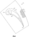
- FIG 2 illustrates an example component 50 that can be incorporated into a gas turbine engine, such as the gas turbine engine 20 of Figure 1 .
- the component 50 includes a body portion 52 that axially extends between a leading edge portion 54 and a trailing edge portion 56.
- the body portion 52 also extends radially outward from a platform 51.
- the body portion 52 may further include a first (pressure) side wall 58 and a second (suction) side wall 60 that are spaced apart from one another and axially extend between the leading edge portion 54 and the trailing edge portion 56. Although shown in cross-section, the body portion 52 would also extend radially across a span.
- the body portion 52 is representative of an airfoil.
- the body portion 52 could be an airfoil that extends from the platform 51 and root portions (i.e., when the component is a blade), or could alternatively extend between inner and outer platforms 51 (i.e., when the component 50 is a vane).
- the component 50 could include a non-airfoil component body spanning, or partially spanning, the flowpath and supported by one or more platforms 51.
- a cooling scheme 64 may be disposed inside of the platform 51 for cooling the internal and external surface areas of the platform 51.
- the exemplary cooling scheme 64 may include one or more vascular engineered lattice structures 80 that are disposed inside portions of the platform 51 of the component 50.
- the component 50 could include greater or fewer vascular engineered lattice structures than are shown in Figure 2 .
- Discrete portions of the component 50 may embody a vascular engineered lattice structure 80, or the entire component 50 can be constructed of a vascular engineered lattice structure. Multiple non-limiting embodiments of such vascular engineered lattice structures are described in detail below with regards to Figures 6-12 .
- Figure 3 schematically illustrates a side view of a rotor blade 210 in an installed configuration within an exemplary gas turbine engine, such as the gas turbine engine 20 of Figure 1 .
- the rotor blade 210 is a rotor blade including a flowpath body 212 protruding radially outward into the primary flowpath, and a platform 214 supporting the flowpath body 212.
- the platform 214 is connected to a rotor disk 220 via a fir tree interface 222 at a root 216 of the rotor blade 210.
- the root 216 is connected to the platform 214 via a neck 218 that extends radially outward from the fir tree interface 222.
- different interface styles may be used, in place of the fir tree interface 222, to connect the blade 210 to the rotor disk 220.
- the vane 240 forward of the rotor disk 220 is a vane 240.
- the vane 240 includes a flowpath body 242 supported by a radially inward platform 244 and a radially outward platform 246.
- Each of the platforms 244, 246 is connected to a corresponding gas turbine engine static structure.
- a cooling cavity 250 is disposed radially inward of the primary flowpath. Air from the cooling cavity 250 is provided to internal cooling passages 211 of the rotor blade 210 using any known cooling system.
- the internal cooling passages 211 provide direct cooling to the rotor blade 210. In alternative examples, alternative cooling systems may be utilized.
- a seal 260 seals the cavity 250, and prevents hot flow from the primary flowpath from entering the cooling cavity 250.
- cooling air is allowed to leak outward through the seal 260, along an air leakage pathway 262.
- the air passing along the air leakage pathway 262 is referred to as purge air.
- the air leakage pathway 262 enters a neck cavity 264 positioned between the platform 214 and the fir tree connection 222 on the rotor disk 220.
- the air leakage pathway 262 also passes through a gap 266 between the rotor blade 210 and the vane 240. In a conventional example, all of the purge air passes through the gap 266 and into the flowpath along the air leakage pathway 262.
- the platform 214 includes a vascular engineered lattice structure 270 within the platform 214.
- the vascular engineered lattice structure 270 can be any vascular engineered lattice structure constructed according to the disclosure below, with regards to Figures 6-12 .
- Purge air is allowed to enter the platform, from the neck cavity 264, via one or more inlets 272 disposed on a radially inward facing surface of the platform 214.
- the purge air passes through or around the vascular engineered lattice structure 270 within the platform 214, and provides cooling to the platform 214.
- the purge air exits the platform 214 at one or more exit holes 274, alternately referred to as spent air outlets.
- the exit holes 274 are positioned on a mating face 213 of the platform 214. In alternative examples, the exit holes 274 are positioned on a radially outward facing surface of the platform 214. In yet further alternative examples, the exit holes 274 can be positioned on both the mating face 213 and the radially outward facing surface.
- the vascular engineered lattice structure 270 provides an alternative leakage path while simultaneously allowing for cooling the platform 214 using air that is not directly sourced from a compressor bleed.
- Figures 4A and 4B schematically illustrate isometric views of the rotor blade 210 isolated from the context of the gas turbine engine 20.
- the rotor blade 210 includes a flowpath body 212, a platform 214, a neck portion 218, and a fir tree connection feature 217.
- a cross sectional plane 202 passes through the rotor blade 210, and provides the viewing reference for Figure 5 .
- the flowpath body 212 includes a leading edge 310 and a trailing edge 320, with two surfaces 330 extending between the leading edge 310 and the trailing edge 320.
- the platform 214 includes a circumferentially facing surface 340 referred to as a mating face. The circumferentially facing surface 340 faces a corresponding circumferentially adjacent surface on a rotor blade 210 adjacent to the illustrated rotor blade 210, while the rotor blade 210 is in an installed position.
- One or more openings 272 are included and allow the communication of purge air from the neck cavity 264 (illustrated in Figure 3 ) into the vascular engineered lattice structure 270 within the platform 214.
- the openings 272 are positioned at a forward portion of the platform 214. In alternative examples, the openings 272 can be positioned elsewhere on the platform 214, or distributed about the radially inward facing surface of the platform 214.
- Figure 5 schematically illustrates a cross section of an example blade 210 cut along the viewing plane 202, and in an installed position.
- Each rotor blade 210 is connected to a rotor disk 220 via the fir tree interface 222.
- Purge air passes through the seal 260 (illustrated in Figure 3 ) along an air leakage pathway 262 into the neck cavity 264. Once in the neck cavity 264, a portion of the air passes through a standard leakage pathway between the rotor blades 210 into the primary flowpath. Another portion of the leakage air from the neck cavity passes through the inlet 272 into the vascular engineered lattice structure 270.
- the air entering the inlet 272 passes through internal structures of the vascular engineered lattice structure 270.
- the vascular engineered lattice structure 270 includes hollow members and passages, and the air entering the inlet passes through the hollow members and passages, thereby providing internal cooling via the vascular engineered lattice structure.
- Non-limiting examples of each above described type of vascular engineered lattice structures 270 are described below with regards to Figures 6-12 .
- the air After passing through the vascular engineered lattice structure 270, the air exits via multiple exit holes as described above, and enters the flowpath.
- the vascular engineered lattice structure could be incorporated in a platform supporting any type of flowpath component and is not limited to a blade.
- the vascular engineered lattice structure could be incorporated in and cool one, or both, of the platforms supporting a flow correcting vane, a flowpath pass through, or any other component at least partially spanning the flowpath.
- the vascular engineered lattice structure can extend through the vane and a single vascular engineered lattice structure can be disposed within both platforms.
- the vascular engineered lattice structures in each platform can be wholly independent of each other.
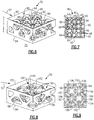
- FIGS 6 and 7 illustrate one exemplary vascular engineered lattice structure 80 that can be incorporated into a component 50.
- the vascular engineered lattice structure 80 may be incorporated into any section or sections of a gas turbine engine component.
- the term "vascular engineered lattice structure" denotes a structure of known surface and flow areas that includes a specific structural integrity.
- the vascular engineered lattice structure 80 of Figures 6 and 7 is a hollow vascular structure.
- the hollow vascular structure shown in Figures 6 and 7 defines a solid material with discrete, interconnected cooling passages that are connected through common nodes to control the flow of airflow throughout the hollow vascular structure.
- the vascular engineered lattice structure 80 of Figure 6 is not intended to be limiting. It will be appreciated that because the vascular engineered lattice structure 80 is an engineered structure, the vascular arrangement of these structures can be tailored to the specific cooling and structural needs of any given gas turbine engine component. In other words, the vascular engineered lattice structure 80 can be tailored to match external heat load and local life requirements by changing the design and density of the vascular engineered lattice structure 80.
- the actual design of any given vascular engineered lattice structure may depend on geometry requirements, pressure loss, local cooling flow, cooling air heat pickup, thermal efficiency, overall cooling effectiveness, aerodynamic mixing, and produceability considerations, among other gas turbine engine specific parameters. In one embodiment, the vascular engineered lattice structure 80 is sized based on a minimum size that can be effectively manufactured and that is not susceptible to becoming plugged by dirt or other debris.
- the exemplary vascular engineered lattice structure 80 extends between a first surface 82 and a second surface 84 of the component.
- the first surface 82 is spaced from the second surface 84.
- the first surface 82 may be exposed to a gas path 62, whereas the second surface 84 may be remotely positioned from the gas path 62.
- the second surface 84 could face radially inward into a neck cavity.
- the vascular engineered lattice structure 80 includes a thickness T between the first surface 82 and the second surface 84.
- the thickness T can be of any dimension.
- Airflow 68 filters through the vascular engineered lattice structure 80 to convectively cool the component 50.
- the term "through” is defined to include either inside of or around the vascular surfaces of the vascular engineered lattice structure.
- the vascular engineered lattice structure 80 embodies a hollow configuration in which the airflow 68 may be circulated inside of the various passages defined by the vascular engineered lattice structure 80.
- the hollow configuration of the vascular engineered lattice structure 80 may establish a porous flow area for the circulation of airflow 68.
- airflow 68 could be communicated over and around the vascular engineered lattice structure 80.
- the vascular engineered lattice structure 80 can be manufactured by using a variety of manufacturing techniques.
- the vascular engineered lattice structure 80 may be created using an additive manufacturing process such as direct metal laser sintering (DMLS).
- Another additive manufacturing process that can be used to manufacture the vascular engineered lattice structure 80 is electron beam melting (EBM).
- EBM electron beam melting
- SLS select laser sintering
- SLM select laser melting
- a casting process can be used to create the vascular engineered lattice structure 80.
- an additive manufacturing process can be used to produce a refractory metal core (RMC), including but not limited to a molybdenum core, that can be used to cast the vascular engineered lattice structure 80.
- RMC refractory metal core
- the additive manufacturing process includes utilizing a powder bed technology and the casting process includes a lost wax process.
- the exemplary vascular engineered lattice structure 80 includes a plurality of nodes 92, a plurality of branches 94 that extend between the nodes 92, and a plurality of hollow passages 96 between the branches 94 and the nodes 92.
- the number, size and distribution of nodes 92, branches 94 and hollow passages 96 can vary from the specific configuration shown. In other words, the configuration illustrated by Figure 7 is but one possible design.
- the branches 94 may extend orthogonally or non-orthogonally to the nodes 92.
- the nodes 92 and branches 94 can be manufactured as a single contiguous structure made of the same material. In one embodiment, the nodes 92 and branches 94 are uniformly distributed throughout the vascular engineered lattice structure 80. In another embodiment, the nodes 92 and branches 94 are non-uniformly distributed throughout the vascular engineered lattice structure 80.
- airflow 68 can be circulated inside hollow passages 96 of the nodes 92 and the branches 94 to cool the component 50 in the space between the walls 82, 84 (see Figure 6 ).
- the "hollow” lattice structure may include multiple continuous hollow spoke cavity passages 96 thru which airflow 68 is passed.
- the airflow 68 flows from each of the hollow branches 94 and coalesces into the nodes 92, which serve as a plenum for the airflow 68 to be redistributed to the next set of hollow branches 94 and nodes 92.
- the "hollow" lattice structure forms multiple circuitous continuous passages in which the airflow 68 flows to maximize the internal convective cooling surface area and coolant mixing. Additionally, airflow 68 could be communicated over and around the nodes 92 and branches 94 of the vascular engineered lattice structure 80.
- the nodes 92 and the branches 94 additionally act as structural members that can be tailored to "tune" steady and unsteady airfoil vibration responses in order to resist and optimally manage steady and unsteady pressure forces, centrifugal bending and curling stresses, as well as provide for improved airfoil local and section average creep and untwist characteristics and capability.
- one or more of the nodes 92 and branches 94 may include augmentation features 95 (shown schematically in Figure 7 ) that augment the heat transfer effect of the airflow 68 as it is communicated through the vascular engineered lattice structure 80.
- the augmentation features 95 can also be made using the additive manufacturing processes describe above.
- vascular arrangement of the vascular engineered lattice structure 80 can be tailored to the specific cooling and structural needs of any given gas turbine engine component.
- a first portion of the vascular engineered lattice structure 80 can include a different combination of nodes 92, braches 94 and hollow passages 96 compared to a second portion of the vascular engineered lattice structure 80.
- a first portion of the vascular engineered lattice structure 80 may include a greater amount of cooling area whereas a second portion of the vascular engineered lattice structure 80 may provide a greater amount of structural area.
- FIGS 8 and 9 illustrate another exemplary vascular engineered lattice structure 180.
- the vascular engineered lattice structure 180 embodies a solid lattice structure in which airflow is communicated over and around the solid lattice structure thereby governing flow and providing structural support.
- the vascular engineered lattice structure 180 is disposed between a first wall 182 and a second wall 184 of the component 50.
- the vascular engineered lattice structure 180 includes a plurality of nodes 192, a plurality of branches 194 that extend between the nodes 92, and a plurality of open passages 196 between the branches 194 and the nodes 192.
- the nodes 192, branches 194 and open passages 196 can be manufactured as a single contiguous structure made of the same material.
- airflow 68 can be circulated through the open passages 196 to cool the component 50 in the space between the walls 182, 184.
- the airflow 68 is circulated over and around these parts as part of a porous flow area.
- the "solid" lattice structure includes multiple continuous solid branches 194 over which airflow 68 is passed.
- the "solid" lattice structure forms circuitous passages for the airflow 68 to traverse around as it migrates through the vascular engineered lattice structure to maximize the convective cooling surface area and coolant mixing around the nodes 192 and the branches 194.
- the nodes 192 and the branches 194 additionally act as structural members that resist pressure, rotation forces, and loads.
- the exemplary vascular engineered lattice structure 180 establishes a ratio of cooling area to structural area.
- the cooling area is established by the open passages 196, while the nodes 192 and branches 194 determine the amount of structural area.
- the amount of cooling area exceeds the structural area (cooling area > structural area).
- a ratio of the cooling area to the structural area is less than 1 (cooling area ⁇ structural area).
- a ratio of the cooling area to the structural area is between 1 and 4.
- Other configurations are also contemplated.
- the vascular engineered lattice structures can be configured in either a co-flow or counter-flow heat exchanger design concepts.
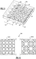
- Figure 10 depicts a vascular engineered lattice structure 280 providing a co-flow design.
- the airflow 68 is circulated through the vascular engineered lattice structure 280 in substantially the same direction as the gas path 62 flow direction.
- a co-flow design could also be incorporated into a "solid" configuration.
- Figure 11 illustrates yet another exemplary vascular engineered lattice structure 380 that could be incorporated into a gas turbine engine component.
- the vascular engineered lattice structure 380 provides a counter-flow design.
- the airflow 68 is circulated through the vascular engineered lattice structure 380 in a direction that is generally opposite to the flow direction of the gas path 62.
- Figure 12 illustrates yet another exemplary vascular engineered lattice structure 480 that could be incorporated into a gas turbine engine component.
- the vascular engineered lattice structure 480 includes a first portion 480A that can include a hollow lattice structure and a second portion 480B that can include a solid lattice structure.
- the distribution of interchangeability of the hollow and solid lattice structures is dependent on design requirements and other considerations.
- vascular engineered lattice structures described in this disclosure may be incorporated into any relatively high heat load gas turbine engine applications where convective cooling is desired.
- the vascular engineered lattice structures of this disclosure may be implemented as a co-flow or counter-flow configurations to more efficiently provide localized convective cooling to achieve extended component operating life.
Landscapes
- Engineering & Computer Science (AREA)
- Mechanical Engineering (AREA)
- General Engineering & Computer Science (AREA)
- Manufacturing & Machinery (AREA)
- Chemical & Material Sciences (AREA)
- Materials Engineering (AREA)
- Physics & Mathematics (AREA)
- Thermal Sciences (AREA)
- Architecture (AREA)
- Turbine Rotor Nozzle Sealing (AREA)
Abstract
Description
- This disclosure relates to a gas turbine engine, and more particularly to a gas turbine engine component having a vascular engineered lattice structure.
- Gas turbine engines typically include a compressor section, a combustor section and a turbine section. In general, during operation, air is pressurized in the compressor section and is mixed with fuel and burned in the combustor section to generate hot combustion gases. The hot combustion gases flow through the turbine section, which extracts energy from the hot combustion gases to power the compressor section and other gas turbine engine loads.
- Due to exposure to hot combustion gases, numerous components of a gas turbine engine may include cooling schemes that circulate airflow to cool the component during engine operation. Thermal energy is transferred from the component to the airflow as the airflow circulates through the cooling scheme to cool the component. Known cooling schemes may be inefficient and lack structural integrity.
- In one exemplary embodiment a flowpath component for a gas turbine engine includes a first platform including a vascular engineered lattice structure, a body extending from, and supported by the first platform. The body being configured to at least partially span a flowpath in an installed position and the vascular engineered lattice structure including at least one purge air inlet, and at least one spent air outlet.
- In another exemplary embodiment of the above described flowpath component for a gas turbine engine the at least one purge air inlet is an opening on a radially inward facing surface of the platform.
- In another exemplary embodiment of any of the above described flowpath components for a gas turbine engine the radially inward facing surface of the platform at least partially defines a neck cavity.
- In another exemplary embodiment of any of the above described flowpath components for a gas turbine engine the at least one spent air outlet includes at least one opening on a mating surface of the platform.
- In another exemplary embodiment of any of the above described flowpath components for a gas turbine engine the mating surface is configured to face a mating surface of an adjacent platform in an installed configuration.
- In another exemplary embodiment of any of the above described flowpath components for a gas turbine engine the at least one spent air outlet includes at least one opening on a gas path surface of the platform.
- In another exemplary embodiment of any of the above described flowpath components for a gas turbine engine the at least one spent air outlet includes at least one opening on a mating surface of the platform.
- In another exemplary embodiment of any of the above described flowpath components for a gas turbine engine the gas path surface is a radially outward facing surface of the platform.
- In another exemplary embodiment of any of the above described flowpath components for a gas turbine engine the purge air inlet is configured to admit air sourced in a cavity circumferentially adjacent a neck of the flowpath component.
- In another exemplary embodiment of any of the above described flowpath components for a gas turbine engine the body is supported between the first platform and a second platform, the second platform being spaced radially apart from the first platform, relative to an installed orientation of the flowpath component.
- In another exemplary embodiment of any of the above described flowpath components for a gas turbine engine each of the first platform and the second platform include a vascular engineered lattice structure.
- In another exemplary embodiment of any of the above described flowpath components for a gas turbine engine the vascular engineered lattice structures are connected as a single vascular engineering lattice structure.
- In another exemplary embodiment of any of the above described flowpath components for a gas turbine engine each of the vascular engineered lattice structures is independent of each other of the vascular engineered lattice structures.
- In one exemplary embodiment a cooling system for a gas turbine engine includes a flowpath component having a first platform including a vascular engineered lattice structure and a body extending radially from the platform, the body at least partially spanning a flowpath and a purge air source adjacent a root of the flowpath component and fluidly connected to the vascular engineered lattice structure.
- In another exemplary embodiment of the above described cooling system for a gas turbine engine the first platform further includes a radially inward facing surface at least partially defining a neck cavity, the radially inward facing surface further including at least one inlet to the vascular engineered lattice structure.
- In another exemplary embodiment of any of the above described cooling systems for a gas turbine engine the first platform further includes a radially outward facing surface having a plurality of exit holes fluidly connecting the vascular engineered lattice structure to a primary flowpath.
- In another exemplary embodiment of any of the above described cooling systems for a gas turbine engine the exit holes are positioned on an aft half of the radially outward facing surface.
- In another exemplary embodiment of any of the above described cooling systems for a gas turbine engine the first platform further includes a radially outward facing mating surface, and wherein the radially outward facing mating surface includes at least one exit hole fluidly connecting the vascular engineered lattice structure to a primary flowpath.
- In another exemplary embodiment of any of the above described cooling systems for a gas turbine engine the first platform further includes a radially outward facing surface having a second plurality of exit holes fluidly connecting the vascular engineered lattice structure to a primary flowpath.
- An exemplary method of cooling a platform within a gas turbine engine, which the Applicant expressly reserves the right to claim, includes supporting at least one flowpath component via a first platform, passing cooling air through a vascular engineered lattice structure within the platform, thereby cooling at least one external surface of the platform, and expelling air from the vascular engineered lattice structure into a primary flowpath of the gas turbine engine.
- The various features and advantages of this disclosure will become apparent to those skilled in the art from the following detailed description. The drawings that accompany the detailed description can be briefly described as follows.
-
-
Figure 1 illustrates a schematic, cross-sectional view of a gas turbine engine. -
Figure 2 schematically illustrates a radially inward facing view of a flowpath component from a radially outward position. -
Figure 3 schematically illustrates a side view of a flowpath component in an installed configuration within an exemplary gas turbine engine. -
Figure 4A schematically illustrates an isometric view of the flowpath component ofFigure 3 . -
Figure 4B schematically illustrates another isometric view of the flowpath component ofFigure 3 . -
Figure 5 schematically illustrates an aft facing view of a partial section of a gas turbine engine from a forward position. -
Figure 6 shows one exemplary vascular engineered lattice structure of a gas turbine engine component. -
Figure 7 illustrates another view of the vascular engineered lattice structure ofFigure 6 . -
Figure 8 illustrates another exemplary vascular engineered lattice structure. -
Figure 9 illustrates another view of the vascular engineered lattice structure ofFigure 8 . -
Figure 10 illustrates another vascular engineered lattice structure embodiment having a co-flow design. -
Figure 11 illustrates another embodiment of a vascular engineered lattice structure embodying a counter-flow design. -
Figure 12 illustrates yet another exemplary vascular engineered lattice structure. -
Figure 1 schematically illustrates agas turbine engine 20. The exemplarygas turbine engine 20 is a two-spool turbofan engine that generally incorporates afan section 22, acompressor section 24, acombustor section 26 and aturbine section 28. Alternative engines might include an augmenter section (not shown) among other systems for features. Thefan section 22 drives air along a bypass flow path B, while thecompressor section 24 drives air along a core flow path C for compression and communication into thecombustor section 26. The hot combustion gases generated in thecombustor section 26 are expanded through theturbine section 28. Although depicted as a turbofan gas turbine engine in the disclosed non-limiting embodiment, it should be understood that the concepts described herein are not limited to turbofan engines and these teachings could extend to other types of engines, including but not limited to, three-spool engine architectures. - The
gas turbine engine 20 generally includes alow speed spool 30 and ahigh speed spool 32 mounted for rotation about an engine centerline longitudinal axis A. Thelow speed spool 30 and thehigh speed spool 32 may be mounted relative to an enginestatic structure 33 viaseveral bearing systems 31. It should be understood thatother bearing systems 31 may alternatively or additionally be provided. - The
low speed spool 30 generally includes aninner shaft 34 that interconnects afan 36, alow pressure compressor 38 and a low pressure turbine 39. Theinner shaft 34 can be connected to thefan 36 through a gearedarchitecture 45 to drive thefan 36 at a lower speed than thelow speed spool 30. Thehigh speed spool 32 includes anouter shaft 35 that interconnects ahigh pressure compressor 37 and ahigh pressure turbine 40. In this embodiment, theinner shaft 34 and theouter shaft 35 are supported at various axial locations bybearing systems 31 positioned within the enginestatic structure 33. - A
combustor 42 is arranged between thehigh pressure compressor 37 and thehigh pressure turbine 40. Amid-turbine frame 44 may be arranged generally between thehigh pressure turbine 40 and the low pressure turbine 39. Themid-turbine frame 44 can support one or more bearingsystems 31 of theturbine section 28. Themid-turbine frame 44 may include one ormore airfoils 46 that extend within the core flow path C. - The
inner shaft 34 and theouter shaft 35 are concentric and rotate via thebearing systems 31 about the engine centerline longitudinal axis A, which is co-linear with their longitudinal axes. The core airflow is compressed by thelow pressure compressor 38 and thehigh pressure compressor 37, is mixed with fuel and burned in thecombustor 42, and is then expanded over thehigh pressure turbine 40 and the low pressure turbine 39. Thehigh pressure turbine 40 and the low pressure turbine 39 rotationally drive the respectivehigh speed spool 32 and thelow speed spool 30 in response to the expansion. - The pressure ratio of the low pressure turbine 39 can be pressure measured prior to the inlet of the low pressure turbine 39 as related to the pressure at the outlet of the low pressure turbine 39 and prior to an exhaust nozzle of the
gas turbine engine 20. In one non-limiting embodiment, the bypass ratio of thegas turbine engine 20 is greater than about ten (10:1), the fan diameter is significantly larger than that of thelow pressure compressor 38, and the low pressure turbine 39 has a pressure ratio that is greater than about five (5:1). It should be understood, however, that the above parameters are only exemplary of one embodiment of a geared architecture engine and that the present disclosure is applicable to other gas turbine engines, including direct drive turbofans. - In this embodiment of the exemplary
gas turbine engine 20, a significant amount of thrust is provided by the bypass flow path B due to the high bypass ratio. Thefan section 22 of thegas turbine engine 20 is designed for a particular flight condition--typically cruise at about 0.8 Mach and about 35,000 feet (10,668 metres). This flight condition, with thegas turbine engine 20 at its best fuel consumption, is also known as bucket cruise Thrust Specific Fuel Consumption (TSFC). TSFC is an industry standard parameter of fuel consumption per unit of thrust. - Fan Pressure Ratio is the pressure ratio across a blade of the
fan section 22 without the use of a Fan Exit Guide Vane system. The low Fan Pressure Ratio according to one non-limiting embodiment of the examplegas turbine engine 20 is less than 1.45. Low Corrected Fan Tip Speed is the actual fan tip speed divided by an industry standard temperature correction of [(Tram °R) / (518.7 °R)]0.5(where °R = K x 9/5). The Low Corrected Fan Tip Speed according to one non-limiting embodiment of the examplegas turbine engine 20 is less than about 1150 fps (351 m/s). - Each of the
compressor section 24 and theturbine section 28 may include alternating rows of rotor assemblies and vane assemblies (shown schematically) that carry airfoils that extend into the core flow path C. For example, the rotor assemblies can carry a plurality ofrotating blades 25, while each vane assembly can carry a plurality ofvanes 27 that extend into the core flow path C. Theblades 25 create or extract energy (in the form of pressure) from the core airflow that is communicated through thegas turbine engine 20 along the core flow path C. Thevanes 27 direct the core airflow to theblades 25 to either add or extract energy. - Various components of the
gas turbine engine 20, including but not limited to the airfoils of theblades 25 and of thevanes 27 in thecompressor section 24 and theturbine section 28, may be subjected to repetitive thermal cycling under widely ranging temperatures and pressures. The hardware of theturbine section 28 is particularly subjected to relatively extreme operating conditions. Therefore, some components may require internal cooling schemes for cooling the parts during engine operation. - Among other features, this disclosure relates to gas turbine engine component cooling schemes that include vascular engineered lattice structures inside platforms supporting flowpath bodies in the primary flowpath. The exemplary structures described herein provide effective localized convective cooling for flowpath component platforms that may be subject to the hot combustion gases that are communicated through the core flow path C.
-
Figure 2 illustrates anexample component 50 that can be incorporated into a gas turbine engine, such as thegas turbine engine 20 ofFigure 1 . Thecomponent 50 includes abody portion 52 that axially extends between aleading edge portion 54 and a trailingedge portion 56. Thebody portion 52 also extends radially outward from aplatform 51. Thebody portion 52 may further include a first (pressure)side wall 58 and a second (suction)side wall 60 that are spaced apart from one another and axially extend between theleading edge portion 54 and the trailingedge portion 56. Although shown in cross-section, thebody portion 52 would also extend radially across a span. - In this embodiment, the
body portion 52 is representative of an airfoil. For example, thebody portion 52 could be an airfoil that extends from theplatform 51 and root portions (i.e., when the component is a blade), or could alternatively extend between inner and outer platforms 51 (i.e., when thecomponent 50 is a vane). In yet another embodiment, thecomponent 50 could include a non-airfoil component body spanning, or partially spanning, the flowpath and supported by one ormore platforms 51. - A cooling
scheme 64 may be disposed inside of theplatform 51 for cooling the internal and external surface areas of theplatform 51. Theexemplary cooling scheme 64 may include one or more vascular engineeredlattice structures 80 that are disposed inside portions of theplatform 51 of thecomponent 50. Of course, thecomponent 50 could include greater or fewer vascular engineered lattice structures than are shown inFigure 2 . Discrete portions of thecomponent 50 may embody a vascular engineeredlattice structure 80, or theentire component 50 can be constructed of a vascular engineered lattice structure. Multiple non-limiting embodiments of such vascular engineered lattice structures are described in detail below with regards toFigures 6-12 . - With continued reference to
Figures 1 and2 ,Figure 3 schematically illustrates a side view of arotor blade 210 in an installed configuration within an exemplary gas turbine engine, such as thegas turbine engine 20 ofFigure 1 . In the illustration ofFigure 3 , therotor blade 210 is a rotor blade including aflowpath body 212 protruding radially outward into the primary flowpath, and aplatform 214 supporting theflowpath body 212. Theplatform 214 is connected to arotor disk 220 via afir tree interface 222 at aroot 216 of therotor blade 210. Theroot 216 is connected to theplatform 214 via aneck 218 that extends radially outward from thefir tree interface 222. In alternative examples, different interface styles may be used, in place of thefir tree interface 222, to connect theblade 210 to therotor disk 220. - Forward of the
rotor disk 220 is avane 240. Thevane 240 includes a flowpath body 242 supported by a radiallyinward platform 244 and a radiallyoutward platform 246. Each of theplatforms - A
cooling cavity 250 is disposed radially inward of the primary flowpath. Air from thecooling cavity 250 is provided tointernal cooling passages 211 of therotor blade 210 using any known cooling system. Theinternal cooling passages 211 provide direct cooling to therotor blade 210. In alternative examples, alternative cooling systems may be utilized. - A
seal 260 seals thecavity 250, and prevents hot flow from the primary flowpath from entering thecooling cavity 250. In order to ensure that no hot gasses flow from the primary flowpath into thecooling cavity 250 through theseal 260, cooling air is allowed to leak outward through theseal 260, along anair leakage pathway 262. In some examples, the air passing along theair leakage pathway 262 is referred to as purge air. - The
air leakage pathway 262 enters aneck cavity 264 positioned between theplatform 214 and thefir tree connection 222 on therotor disk 220. Theair leakage pathway 262 also passes through agap 266 between therotor blade 210 and thevane 240. In a conventional example, all of the purge air passes through thegap 266 and into the flowpath along theair leakage pathway 262. - In the illustrated example, the
platform 214 includes a vascular engineeredlattice structure 270 within theplatform 214. The vascular engineeredlattice structure 270 can be any vascular engineered lattice structure constructed according to the disclosure below, with regards toFigures 6-12 . Purge air is allowed to enter the platform, from theneck cavity 264, via one ormore inlets 272 disposed on a radially inward facing surface of theplatform 214. The purge air passes through or around the vascular engineeredlattice structure 270 within theplatform 214, and provides cooling to theplatform 214. The purge air exits theplatform 214 at one or more exit holes 274, alternately referred to as spent air outlets. In some examples, the exit holes 274 are positioned on amating face 213 of theplatform 214. In alternative examples, the exit holes 274 are positioned on a radially outward facing surface of theplatform 214. In yet further alternative examples, the exit holes 274 can be positioned on both themating face 213 and the radially outward facing surface. - In this way, the vascular engineered
lattice structure 270 provides an alternative leakage path while simultaneously allowing for cooling theplatform 214 using air that is not directly sourced from a compressor bleed. - With continued reference to
Figure 3 ,Figures 4A and4B schematically illustrate isometric views of therotor blade 210 isolated from the context of thegas turbine engine 20. As described above, therotor blade 210 includes aflowpath body 212, aplatform 214, aneck portion 218, and a firtree connection feature 217. A crosssectional plane 202 passes through therotor blade 210, and provides the viewing reference forFigure 5 . Theflowpath body 212 includes aleading edge 310 and a trailingedge 320, with twosurfaces 330 extending between theleading edge 310 and the trailingedge 320. Theplatform 214 includes acircumferentially facing surface 340 referred to as a mating face. Thecircumferentially facing surface 340 faces a corresponding circumferentially adjacent surface on arotor blade 210 adjacent to the illustratedrotor blade 210, while therotor blade 210 is in an installed position. - Positioned on the
circumferentially facing surface 340 are multiple exit holes 342. Positioned on the aft end of theplatform 214 are multiple exit holes 344. The exit holes 342, 344 allow purge air that has passed through the vascular engineeredlattice structure 270 to exit theplatform 214 into the flowpath. One or more openings 272 (hidden inFigure 4A ) are included and allow the communication of purge air from the neck cavity 264 (illustrated inFigure 3 ) into the vascular engineeredlattice structure 270 within theplatform 214. In the illustrated example, theopenings 272 are positioned at a forward portion of theplatform 214. In alternative examples, theopenings 272 can be positioned elsewhere on theplatform 214, or distributed about the radially inward facing surface of theplatform 214. - With continued reference to
Figures 2-4B ,Figure 5 schematically illustrates a cross section of anexample blade 210 cut along theviewing plane 202, and in an installed position. Eachrotor blade 210 is connected to arotor disk 220 via thefir tree interface 222. Purge air passes through the seal 260 (illustrated inFigure 3 ) along anair leakage pathway 262 into theneck cavity 264. Once in theneck cavity 264, a portion of the air passes through a standard leakage pathway between therotor blades 210 into the primary flowpath. Another portion of the leakage air from the neck cavity passes through theinlet 272 into the vascular engineeredlattice structure 270. - In some examples, the air entering the
inlet 272 passes through internal structures of the vascular engineeredlattice structure 270. In alternative examples, the vascular engineeredlattice structure 270 includes hollow members and passages, and the air entering the inlet passes through the hollow members and passages, thereby providing internal cooling via the vascular engineered lattice structure. Non-limiting examples of each above described type of vascular engineeredlattice structures 270 are described below with regards toFigures 6-12 . - After passing through the vascular engineered
lattice structure 270, the air exits via multiple exit holes as described above, and enters the flowpath. - While illustrated and described above with regards to utilization within a platform supporting a rotor blade, one of skill in the art having the benefit of this disclosure will appreciate that the vascular engineered lattice structure could be incorporated in a platform supporting any type of flowpath component and is not limited to a blade. By way of example, the vascular engineered lattice structure could be incorporated in and cool one, or both, of the platforms supporting a flow correcting vane, a flowpath pass through, or any other component at least partially spanning the flowpath. In the example of a vane supported by two platforms, the vascular engineered lattice structure can extend through the vane and a single vascular engineered lattice structure can be disposed within both platforms. In alternative examples of a vane supported by two platforms, the vascular engineered lattice structures in each platform can be wholly independent of each other.
-
Figures 6 and 7 illustrate one exemplary vascularengineered lattice structure 80 that can be incorporated into acomponent 50. The vascular engineeredlattice structure 80 may be incorporated into any section or sections of a gas turbine engine component. In this disclosure, the term "vascular engineered lattice structure" denotes a structure of known surface and flow areas that includes a specific structural integrity. - As discussed in greater detail below, the vascular engineered
lattice structure 80 ofFigures 6 and 7 is a hollow vascular structure. The hollow vascular structure shown inFigures 6 and 7 defines a solid material with discrete, interconnected cooling passages that are connected through common nodes to control the flow of airflow throughout the hollow vascular structure. - The specific design and configuration of the vascular engineered
lattice structure 80 ofFigure 6 is not intended to be limiting. It will be appreciated that because the vascular engineeredlattice structure 80 is an engineered structure, the vascular arrangement of these structures can be tailored to the specific cooling and structural needs of any given gas turbine engine component. In other words, the vascular engineeredlattice structure 80 can be tailored to match external heat load and local life requirements by changing the design and density of the vascular engineeredlattice structure 80. The actual design of any given vascular engineered lattice structure may depend on geometry requirements, pressure loss, local cooling flow, cooling air heat pickup, thermal efficiency, overall cooling effectiveness, aerodynamic mixing, and produceability considerations, among other gas turbine engine specific parameters. In one embodiment, the vascular engineeredlattice structure 80 is sized based on a minimum size that can be effectively manufactured and that is not susceptible to becoming plugged by dirt or other debris. - The exemplary vascular
engineered lattice structure 80 extends between afirst surface 82 and asecond surface 84 of the component. Thefirst surface 82 is spaced from thesecond surface 84. Thefirst surface 82 may be exposed to agas path 62, whereas thesecond surface 84 may be remotely positioned from thegas path 62. For example, thesecond surface 84 could face radially inward into a neck cavity. The vascular engineeredlattice structure 80 includes a thickness T between thefirst surface 82 and thesecond surface 84. The thickness T can be of any dimension. -
Airflow 68 filters through the vascular engineeredlattice structure 80 to convectively cool thecomponent 50. In this disclosure, the term "through" is defined to include either inside of or around the vascular surfaces of the vascular engineered lattice structure. In one embodiment, the vascular engineeredlattice structure 80 embodies a hollow configuration in which theairflow 68 may be circulated inside of the various passages defined by the vascular engineeredlattice structure 80. For example, the hollow configuration of the vascular engineeredlattice structure 80 may establish a porous flow area for the circulation ofairflow 68. Additionally,airflow 68 could be communicated over and around the vascular engineeredlattice structure 80. - The vascular engineered
lattice structure 80 can be manufactured by using a variety of manufacturing techniques. For example, the vascular engineeredlattice structure 80 may be created using an additive manufacturing process such as direct metal laser sintering (DMLS). Another additive manufacturing process that can be used to manufacture the vascular engineeredlattice structure 80 is electron beam melting (EBM). In another embodiment, select laser sintering (SLS) or select laser melting (SLM) processes may be utilized. - In yet another embodiment, a casting process can be used to create the vascular engineered
lattice structure 80. For example, an additive manufacturing process can be used to produce a refractory metal core (RMC), including but not limited to a molybdenum core, that can be used to cast the vascular engineeredlattice structure 80. In one embodiment, the additive manufacturing process includes utilizing a powder bed technology and the casting process includes a lost wax process. - The exemplary vascular
engineered lattice structure 80 includes a plurality ofnodes 92, a plurality ofbranches 94 that extend between thenodes 92, and a plurality ofhollow passages 96 between thebranches 94 and thenodes 92. The number, size and distribution ofnodes 92,branches 94 andhollow passages 96 can vary from the specific configuration shown. In other words, the configuration illustrated byFigure 7 is but one possible design. - The
branches 94 may extend orthogonally or non-orthogonally to thenodes 92. Thenodes 92 andbranches 94 can be manufactured as a single contiguous structure made of the same material. In one embodiment, thenodes 92 andbranches 94 are uniformly distributed throughout the vascular engineeredlattice structure 80. In another embodiment, thenodes 92 andbranches 94 are non-uniformly distributed throughout the vascular engineeredlattice structure 80. - In this "hollow lattice" structure configuration,
airflow 68 can be circulated insidehollow passages 96 of thenodes 92 and thebranches 94 to cool thecomponent 50 in the space between thewalls 82, 84 (seeFigure 6 ). For example, the "hollow" lattice structure may include multiple continuous hollow spokecavity passages 96 thru which airflow 68 is passed. Theairflow 68 flows from each of thehollow branches 94 and coalesces into thenodes 92, which serve as a plenum for theairflow 68 to be redistributed to the next set ofhollow branches 94 andnodes 92. The "hollow" lattice structure forms multiple circuitous continuous passages in which theairflow 68 flows to maximize the internal convective cooling surface area and coolant mixing. Additionally,airflow 68 could be communicated over and around thenodes 92 andbranches 94 of the vascular engineeredlattice structure 80. - The
nodes 92 and thebranches 94 additionally act as structural members that can be tailored to "tune" steady and unsteady airfoil vibration responses in order to resist and optimally manage steady and unsteady pressure forces, centrifugal bending and curling stresses, as well as provide for improved airfoil local and section average creep and untwist characteristics and capability. In one embodiment, one or more of thenodes 92 andbranches 94 may include augmentation features 95 (shown schematically inFigure 7 ) that augment the heat transfer effect of theairflow 68 as it is communicated through the vascular engineeredlattice structure 80. The augmentation features 95 can also be made using the additive manufacturing processes describe above. - As mentioned above, the vascular arrangement of the vascular engineered
lattice structure 80 can be tailored to the specific cooling and structural needs of any given gas turbine engine component. For example, a first portion of the vascular engineeredlattice structure 80 can include a different combination ofnodes 92,braches 94 andhollow passages 96 compared to a second portion of the vascular engineeredlattice structure 80. In one embodiment, a first portion of the vascular engineeredlattice structure 80 may include a greater amount of cooling area whereas a second portion of the vascular engineeredlattice structure 80 may provide a greater amount of structural area. -
Figures 8 and 9 illustrate another exemplary vascularengineered lattice structure 180. In this embodiment, the vascular engineeredlattice structure 180 embodies a solid lattice structure in which airflow is communicated over and around the solid lattice structure thereby governing flow and providing structural support. The vascular engineeredlattice structure 180 is disposed between afirst wall 182 and asecond wall 184 of thecomponent 50. - The vascular engineered
lattice structure 180 includes a plurality ofnodes 192, a plurality ofbranches 194 that extend between thenodes 92, and a plurality ofopen passages 196 between thebranches 194 and thenodes 192. Thenodes 192,branches 194 andopen passages 196 can be manufactured as a single contiguous structure made of the same material. - In this "solid" lattice structure configuration,
airflow 68 can be circulated through theopen passages 196 to cool thecomponent 50 in the space between thewalls nodes 192 andbraches 194, theairflow 68 is circulated over and around these parts as part of a porous flow area. For example, the "solid" lattice structure includes multiple continuoussolid branches 194 over which airflow 68 is passed. The "solid" lattice structure forms circuitous passages for theairflow 68 to traverse around as it migrates through the vascular engineered lattice structure to maximize the convective cooling surface area and coolant mixing around thenodes 192 and thebranches 194. Thenodes 192 and thebranches 194 additionally act as structural members that resist pressure, rotation forces, and loads. - The exemplary vascular
engineered lattice structure 180 establishes a ratio of cooling area to structural area. The cooling area is established by theopen passages 196, while thenodes 192 andbranches 194 determine the amount of structural area. In one embodiment, the amount of cooling area exceeds the structural area (cooling area > structural area). In another embodiment, a ratio of the cooling area to the structural area is less than 1 (cooling area < structural area). In yet another embodiment, a ratio of the cooling area to the structural area is between 1 and 4. Other configurations are also contemplated. - The vascular engineered lattice structures can be configured in either a co-flow or counter-flow heat exchanger design concepts. For example,
Figure 10 depicts a vascular engineeredlattice structure 280 providing a co-flow design. In other words, theairflow 68 is circulated through the vascular engineeredlattice structure 280 in substantially the same direction as thegas path 62 flow direction. Although a hollow configuration is depicted, a co-flow design could also be incorporated into a "solid" configuration. -
Figure 11 illustrates yet another exemplary vascularengineered lattice structure 380 that could be incorporated into a gas turbine engine component. In this embodiment, the vascular engineeredlattice structure 380 provides a counter-flow design. In other words, theairflow 68 is circulated through the vascular engineeredlattice structure 380 in a direction that is generally opposite to the flow direction of thegas path 62. -
Figure 12 illustrates yet another exemplary vascularengineered lattice structure 480 that could be incorporated into a gas turbine engine component. In this embodiment, the vascular engineeredlattice structure 480 includes afirst portion 480A that can include a hollow lattice structure and asecond portion 480B that can include a solid lattice structure. The distribution of interchangeability of the hollow and solid lattice structures is dependent on design requirements and other considerations. - The exemplary vascular engineered lattice structures described in this disclosure may be incorporated into any relatively high heat load gas turbine engine applications where convective cooling is desired. Among other possible design configurations, the vascular engineered lattice structures of this disclosure may be implemented as a co-flow or counter-flow configurations to more efficiently provide localized convective cooling to achieve extended component operating life.
- Although the different non-limiting embodiments are illustrated as having specific components, the embodiments of this disclosure are not limited to those particular combinations. It is possible to use some of the components or features from any of the non-limiting embodiments in combination with features or components from any of the other non-limiting embodiments.
- It should be understood that like reference numerals identify corresponding or similar elements throughout the several drawings. It should also be understood that although a particular component arrangement is disclosed and illustrated in these exemplary embodiments, other arrangements could also benefit from the teachings of this disclosure.
- The foregoing description shall be interpreted as illustrative and not in any limiting sense. A worker of ordinary skill in the art would understand that certain modifications could come within the scope of this disclosure. For these reasons, the following claims should be studied to determine the true scope and content of this disclosure.
Claims (15)
- A flowpath component (50) for a gas turbine engine (20) comprising:a first platform (51; 214, 244) including a vascular engineered lattice structure (80; 180; 270; 280; 380; 480);a body (52; 212; 242) extending from, and supported by, the first platform (51; 214. 244);the body (52; 212, 242) being configured to at least partially span a flowpath in an installed position; andthe vascular engineered lattice structure (80...480) including at least one purge air inlet (272), and at least one spent air outlet (274; 342, 344).
- The flowpath component of claim 1, wherein the at least one purge air inlet (272) is an opening on a radially inward facing surface of said platform (51; 214), wherein, optionally, the radially inward facing surface of said platform (51; 214) at least partially defines a neck cavity (264).
- The flowpath component of claim 1 or 2, wherein the at least one spent air outlet (274; 342, 344) includes at least one opening (342) on a mating surface (213; 340) of said platform (51; 214).
- The flowpath component of claim 3, wherein the mating surface (213; 340) is configured to face a mating surface of an adjacent platform in an installed configuration.
- The flowpath component of any preceding claim, wherein the at least one spent air outlet (274; 342; 344) includes at least one opening (274; 344) on a gas path surface of the platform (51; 214; 244).
- The flowpath component of claim 5, wherein the gas path surface is a radially outward facing surface of the platform (51; 214).
- The flowpath component of any preceding claim, wherein the purge air inlet (272) is configured to admit air sourced in a cavity (264) circumferentially adjacent a neck (218) of said flowpath component (50).
- The flowpath component of any preceding claim, wherein the body (242) is supported between the first platform (244) and a second platform (246), the second platform (246) being spaced radially apart from the first platform (244), relative to an installed orientation of the flowpath component.
- The flowpath component of claim 8, wherein each of the first platform (244) and the second platform (246) include a vascular engineered lattice structure (80; 180; 280; 380; 480), wherein, optionally, the vascular engineered lattice structures (80...480) are connected as a single vascular engineering lattice structure, or each of the vascular engineered lattice structures (80...480) is independent of each other of the vascular engineered lattice structures (80...480).
- A cooling system for a gas turbine engine (20) comprising:a flowpath component (50) having a first platform (51; 214, 244) including a vascular engineered lattice structure (80; 180; 270; 280; 380; 480) and a body (52; 212; 242) extending radially from said platform (51; 214; 244), the body (52; 212, 242) at least partially spanning a flowpath; anda purge air source (272) adjacent a root (216) of said flowpath component (50) and fluidly connected to the vascular engineered lattice structure (80...480).
- The cooling system of claim 10, wherein the first platform (51; 214) further includes a radially inward facing surface at least partially defining a neck cavity (264), the radially inward facing surface further including at least one inlet (272) to said vascular engineered lattice structure (80...480).
- The cooling system of claim 10 or 11, wherein the first platform (51; 214, 244) further includes a radially outward facing surface having a plurality of exit holes (344) fluidly connecting the vascular engineered lattice structure (80...480) to a primary flowpath.
- The cooling system of claim 12, wherein the exit holes (344) are positioned on an aft half of said radially outward facing surface.
- The cooling system of claim 10 or 11, wherein the first platform (51; 214) further includes a radially outward facing surface, and wherein the radially outward facing surface includes at least one exit hole (344) fluidly connecting the vascular engineered lattice structure (80...480) to a primary flowpath.
- The cooling system of claim 14, wherein the radially outward facing surface has a plurality of exit holes (344) fluidly connecting the vascular engineered lattice structure (80...480) to the primary flowpath.
Applications Claiming Priority (1)
| Application Number | Priority Date | Filing Date | Title |
|---|---|---|---|
| US15/045,644 US10221694B2 (en) | 2016-02-17 | 2016-02-17 | Gas turbine engine component having vascular engineered lattice structure |
Publications (1)
| Publication Number | Publication Date |
|---|---|
| EP3208424A1 true EP3208424A1 (en) | 2017-08-23 |
Family
ID=58046594
Family Applications (1)
| Application Number | Title | Priority Date | Filing Date |
|---|---|---|---|
| EP17156353.9A Withdrawn EP3208424A1 (en) | 2016-02-17 | 2017-02-15 | Gas turbine engine component having vascular engineered lattice structure |
Country Status (2)
| Country | Link |
|---|---|
| US (1) | US10221694B2 (en) |
| EP (1) | EP3208424A1 (en) |
Cited By (1)
| Publication number | Priority date | Publication date | Assignee | Title |
|---|---|---|---|---|
| EP3854993A3 (en) * | 2020-01-22 | 2021-08-18 | General Electric Company | Turbine rotor blade roots |
Families Citing this family (19)
| Publication number | Priority date | Publication date | Assignee | Title |
|---|---|---|---|---|
| US10557464B2 (en) | 2015-12-23 | 2020-02-11 | Emerson Climate Technologies, Inc. | Lattice-cored additive manufactured compressor components with fluid delivery features |
| US10982672B2 (en) | 2015-12-23 | 2021-04-20 | Emerson Climate Technologies, Inc. | High-strength light-weight lattice-cored additive manufactured compressor components |
| US10634143B2 (en) * | 2015-12-23 | 2020-04-28 | Emerson Climate Technologies, Inc. | Thermal and sound optimized lattice-cored additive manufactured compressor components |
| US20180056100A1 (en) | 2016-08-31 | 2018-03-01 | Emerson Process Management Regulator Technologies Tulsa, Llc | Method for Manufacturing a Flame Arrestor |
| US9987508B2 (en) * | 2016-08-31 | 2018-06-05 | Emerson Process Management Regulator Technologies Tulsa, Llc | Hybrid composite flame cell |
| US20200102943A1 (en) * | 2018-10-02 | 2020-04-02 | Vilter Manufacturing Llc | 3D-Printed Oil Separation for Reciprocating Compressors |
| US11156100B2 (en) * | 2018-12-04 | 2021-10-26 | Raytheon Technologies Corporation | Composite fan blade |
| FR3092137B1 (en) * | 2019-01-30 | 2021-02-12 | Safran Aircraft Engines | Turbomachine stator sector with high stress areas |
| US11326516B2 (en) * | 2019-08-15 | 2022-05-10 | Pratt & Whitney Canada Corp. | Removal of contaminants from air for use in aircraft engines |
| US11542844B2 (en) | 2019-09-20 | 2023-01-03 | Raytheon Technologies Corporation | Integrated lubricating fluid filtering and metering device |
| DE102020201448A1 (en) | 2020-02-06 | 2021-08-12 | Siemens Aktiengesellschaft | Additively manufactured turbine blade with anti-twist device and adjustment process |
| FR3114838B1 (en) * | 2020-10-01 | 2023-06-16 | Safran Aircraft Engines | Turbine blade for an aircraft turbomachine, comprising a platform provided with a primary flow rejection channel towards a purge cavity |
| CN112943378B (en) * | 2021-02-04 | 2022-06-28 | 大连理工大学 | Turbine blade branch net type cooling structure |
| US20230078480A1 (en) * | 2021-09-10 | 2023-03-16 | Hamilton Sundstrand Corporation | Turbomachinery housing with variable lattice densities |
| US11802488B2 (en) | 2021-09-10 | 2023-10-31 | Hamilton Sundstrand Corporation | Turbomachinery seal plate with variable lattice densities |
| US11773746B2 (en) | 2021-09-10 | 2023-10-03 | Hamilton Sundstrand Corporation | Turbomachinery rotor shroud with variable lattice densities |
| US11994141B2 (en) | 2021-09-10 | 2024-05-28 | Hamilton Sundstrand Corporation | Turbomachinery shaft with variable lattice densities |
| FR3133063B1 (en) * | 2022-02-25 | 2024-08-02 | Safran Aircraft Engines | Turbomachine blading, comprising a blade and a platform which has an internal flow suction and ejection channel. |
| US12055062B2 (en) | 2022-10-28 | 2024-08-06 | Rtx Corporation | Gas turbine engine support structure with internal lattice |
Citations (6)
| Publication number | Priority date | Publication date | Assignee | Title |
|---|---|---|---|---|
| EP1726785A2 (en) * | 2005-05-23 | 2006-11-29 | United Technologies Corporation | Turbine airfoil platform cooling circuit |
| WO2015026430A1 (en) * | 2013-08-20 | 2015-02-26 | United Technologies Corporation | Ducting platform cover plate |
| WO2015057310A2 (en) * | 2013-09-17 | 2015-04-23 | United Technologies Corporation | Platform cooling core for a gas turbine engine rotor blade |
| US20150218962A1 (en) * | 2014-02-06 | 2015-08-06 | General Electric Company | Micro channel and methods of manufacturing a micro channel |
| EP2947274A1 (en) * | 2014-05-22 | 2015-11-25 | United Technologies Corporation | Turbulating cooling structures |
| US20150345304A1 (en) * | 2012-12-28 | 2015-12-03 | United Technologies Corporation | Gas turbine engine component having vascular engineered lattice structure |
Family Cites Families (88)
| Publication number | Priority date | Publication date | Assignee | Title |
|---|---|---|---|---|
| US3584972A (en) | 1966-02-09 | 1971-06-15 | Gen Motors Corp | Laminated porous metal |
| US3864199A (en) | 1973-07-26 | 1975-02-04 | Gen Motors Corp | Angular discharge porous sheet |
| US3900629A (en) | 1973-09-14 | 1975-08-19 | Bendix Corp | Porous laminate and method of manufacture |
| US4168348A (en) | 1974-12-13 | 1979-09-18 | Rolls-Royce Limited | Perforated laminated material |
| US4004056A (en) | 1975-07-24 | 1977-01-18 | General Motors Corporation | Porous laminated sheet |
| NL7606801A (en) | 1975-10-01 | 1977-04-05 | Gen Electric | SMOOTH BRAIDED METAL SKIN AND METHOD OF MANUFACTURE THIS. |
| US4359181A (en) | 1978-05-25 | 1982-11-16 | John Chisholm | Process for making a high heat transfer surface composed of perforated or expanded metal |
| GB2033071B (en) | 1978-10-28 | 1982-07-21 | Rolls Royce | Sheet metal laminate |
| US4269032A (en) | 1979-06-13 | 1981-05-26 | General Motors Corporation | Waffle pattern porous material |
| US4302940A (en) | 1979-06-13 | 1981-12-01 | General Motors Corporation | Patterned porous laminated material |
| FR2483513A1 (en) | 1980-05-28 | 1981-12-04 | Snecma | PROCESS FOR THE MANUFACTURE OF TURBINE BLADES COOLED WITH A POROUS BODY AND PRODUCT OBTAINED ACCORDING TO SAID PROCESS |
| US4407632A (en) * | 1981-06-26 | 1983-10-04 | United Technologies Corporation | Airfoil pedestaled trailing edge region cooling configuration |
| US4751962A (en) | 1986-02-10 | 1988-06-21 | General Motors Corporation | Temperature responsive laminated porous metal panel |
| GB8910241D0 (en) | 1989-05-04 | 1989-06-21 | Secretary Trade Ind Brit | Heat exchangers |
| US5197852A (en) * | 1990-05-31 | 1993-03-30 | General Electric Company | Nozzle band overhang cooling |
| EP0475658A1 (en) | 1990-09-06 | 1992-03-18 | General Electric Company | Turbine blade airfoil with serial impingement cooling through internal cavity-forming ribs |
| US5660523A (en) | 1992-02-03 | 1997-08-26 | General Electric Company | Turbine blade squealer tip peripheral end wall with cooling passage arrangement |
| US5370499A (en) | 1992-02-03 | 1994-12-06 | General Electric Company | Film cooling of turbine airfoil wall using mesh cooling hole arrangement |
| US5295530A (en) | 1992-02-18 | 1994-03-22 | General Motors Corporation | Single-cast, high-temperature, thin wall structures and methods of making the same |
| EP0564027A1 (en) | 1992-03-31 | 1993-10-06 | Akzo Nobel N.V. | Heat exchanger, a method of manufacturing same, and applications |
| DE4338457C2 (en) | 1993-11-11 | 1998-09-03 | Mtu Muenchen Gmbh | Component made of metal or ceramic with a dense outer shell and porous core and manufacturing process |
| US5607778A (en) | 1995-07-20 | 1997-03-04 | Purolator Products Company | Method of manufacturing a porous metal mat |
| US5752801A (en) | 1997-02-20 | 1998-05-19 | Westinghouse Electric Corporation | Apparatus for cooling a gas turbine airfoil and method of making same |
| US5931638A (en) | 1997-08-07 | 1999-08-03 | United Technologies Corporation | Turbomachinery airfoil with optimized heat transfer |
| US5975841A (en) | 1997-10-03 | 1999-11-02 | Thermal Corp. | Heat pipe cooling for turbine stators |
| US5960863A (en) | 1998-01-07 | 1999-10-05 | Hua; Hsu Mei | Dissipating device for computer chips |
| US6167952B1 (en) | 1998-03-03 | 2001-01-02 | Hamilton Sundstrand Corporation | Cooling apparatus and method of assembling same |
| US6126396A (en) | 1998-12-09 | 2000-10-03 | General Electric Company | AFT flowing serpentine airfoil cooling circuit with side wall impingement cooling chambers |
| US6235370B1 (en) | 1999-03-03 | 2001-05-22 | Siemens Westinghouse Power Corporation | High temperature erosion resistant, abradable thermal barrier composite coating |
| JP3632003B2 (en) | 2000-03-07 | 2005-03-23 | 三菱重工業株式会社 | Gas turbine split ring |
| DE10024302A1 (en) | 2000-05-17 | 2001-11-22 | Alstom Power Nv | Process for producing a thermally stressed casting |
| US6397922B1 (en) | 2000-05-24 | 2002-06-04 | Massachusetts Institute Of Technology | Molds for casting with customized internal structure to collapse upon cooling and to facilitate control of heat transfer |
| US6511762B1 (en) | 2000-11-06 | 2003-01-28 | General Electric Company | Multi-layer thermal barrier coating with transpiration cooling |
| US6617003B1 (en) | 2000-11-06 | 2003-09-09 | General Electric Company | Directly cooled thermal barrier coating system |
| US7785098B1 (en) | 2001-06-05 | 2010-08-31 | Mikro Systems, Inc. | Systems for large area micro mechanical systems |
| US7141812B2 (en) | 2002-06-05 | 2006-11-28 | Mikro Systems, Inc. | Devices, methods, and systems involving castings |
| US7063131B2 (en) | 2001-07-12 | 2006-06-20 | Nuvera Fuel Cells, Inc. | Perforated fin heat exchangers and catalytic support |
| GB0117110D0 (en) | 2001-07-13 | 2001-09-05 | Siemens Ag | Coolable segment for a turbomachinery and combustion turbine |
| US6761956B2 (en) | 2001-12-20 | 2004-07-13 | General Electric Company | Ventilated thermal barrier coating |
| EP1327703A1 (en) | 2002-01-15 | 2003-07-16 | Siemens Aktiengesellschaft | Coating system with a porous layer |
| DE10261071A1 (en) | 2002-12-24 | 2004-07-08 | Rolls-Royce Deutschland Ltd & Co Kg | Combustion chamber wall element for gas turbine has outer cover plate, porous center layer and inner cover plate interconnected in one piece, and may be interconnected by one or more diffusion welding processes |
| US7048986B2 (en) | 2003-06-12 | 2006-05-23 | Northrop Grumman Corporation | End gaps of filled honeycomb |
| EP1496140A1 (en) | 2003-07-09 | 2005-01-12 | Siemens Aktiengesellschaft | Layered structure and process for producing a layered structure |
| US7128532B2 (en) | 2003-07-22 | 2006-10-31 | The Boeing Company | Transpiration cooling system |
| US6955523B2 (en) | 2003-08-08 | 2005-10-18 | Siemens Westinghouse Power Corporation | Cooling system for a turbine vane |
| DE10341515A1 (en) | 2003-09-04 | 2005-03-31 | Rolls-Royce Deutschland Ltd & Co Kg | Arrangement for cooling highly heat-stressed components |
| EP1528343A1 (en) | 2003-10-27 | 2005-05-04 | Siemens Aktiengesellschaft | Refractory tile with reinforcing members embedded therein, as liner for gas turbine combustion chamber |
| EP1533113A1 (en) | 2003-11-14 | 2005-05-25 | Siemens Aktiengesellschaft | High temperature layered system for heat dissipation and method for making it |
| US7153464B2 (en) | 2003-12-01 | 2006-12-26 | General Electric Company | Method of making porous ceramic matrix composites |
| DE10360164A1 (en) | 2003-12-20 | 2005-07-21 | Mtu Aero Engines Gmbh | Gas turbine component |
| US20060021308A1 (en) | 2004-07-29 | 2006-02-02 | Merkel Gregory A | Mullite-aluminum titanate body and method for making same |
| US7144220B2 (en) | 2004-07-30 | 2006-12-05 | United Technologies Corporation | Investment casting |
| GB0418906D0 (en) | 2004-08-25 | 2004-09-29 | Rolls Royce Plc | Internally cooled aerofoils |
| US7775053B2 (en) * | 2004-09-20 | 2010-08-17 | United Technologies Corporation | Heat transfer augmentation in a compact heat exchanger pedestal array |
| GB2451779A (en) | 2004-09-22 | 2009-02-11 | Rolls Royce Plc | Manufacturing aerofoil with metal foam core |
| GB0424593D0 (en) | 2004-11-06 | 2004-12-08 | Rolls Royce Plc | A component having a film cooling arrangement |
| US7422417B2 (en) | 2005-05-05 | 2008-09-09 | Florida Turbine Technologies, Inc. | Airfoil with a porous fiber metal layer |
| US7500828B2 (en) | 2005-05-05 | 2009-03-10 | Florida Turbine Technologies, Inc. | Airfoil having porous metal filled cavities |
| US7745022B2 (en) | 2005-07-22 | 2010-06-29 | Siemens Energy, Inc. | CMC with multiple matrix phases separated by diffusion barrier |
| GB2428749B (en) | 2005-08-02 | 2007-11-28 | Rolls Royce Plc | A component comprising a multiplicity of cooling passages |
| US7658590B1 (en) | 2005-09-30 | 2010-02-09 | Florida Turbine Technologies, Inc. | Turbine airfoil with micro-tubes embedded with a TBC |
| JP5372494B2 (en) | 2006-03-17 | 2013-12-18 | 日本碍子株式会社 | Manufacturing method of honeycomb structure |
| GB0605802D0 (en) | 2006-03-23 | 2006-05-03 | Rolls Royce Plc | A heat exchanger |
| US7866372B2 (en) | 2006-12-20 | 2011-01-11 | The Boeing Company | Method of making a heat exchanger core component |
| US7866377B2 (en) | 2006-12-20 | 2011-01-11 | The Boeing Company | Method of using minimal surfaces and minimal skeletons to make heat exchanger components |
| US7810552B2 (en) | 2006-12-20 | 2010-10-12 | The Boeing Company | Method of making a heat exchanger |
| US7597533B1 (en) | 2007-01-26 | 2009-10-06 | Florida Turbine Technologies, Inc. | BOAS with multi-metering diffusion cooling |
| US7717677B1 (en) | 2007-01-31 | 2010-05-18 | Florida Turbine Technologies, Inc. | Multi-metering and diffusion transpiration cooled airfoil |
| US8257809B2 (en) | 2007-03-08 | 2012-09-04 | Siemens Energy, Inc. | CMC wall structure with integral cooling channels |
| US7968144B2 (en) | 2007-04-10 | 2011-06-28 | Siemens Energy, Inc. | System for applying a continuous surface layer on porous substructures of turbine airfoils |
| US20100025001A1 (en) | 2007-06-25 | 2010-02-04 | Ching-Pang Lee | Methods for fabricating gas turbine components using an integrated disposable core and shell die |
| US8167573B2 (en) | 2008-09-19 | 2012-05-01 | Siemens Energy, Inc. | Gas turbine airfoil |
| EP2184445A1 (en) | 2008-11-05 | 2010-05-12 | Siemens Aktiengesellschaft | Axial segmented vane support for a gas turbine |
| ATE528606T1 (en) | 2008-12-16 | 2011-10-15 | Siemens Ag | MULTI-IMPINGEMENT COMPOSITE FOR COOLING A WALL |
| US8079821B2 (en) | 2009-05-05 | 2011-12-20 | Siemens Energy, Inc. | Turbine airfoil with dual wall formed from inner and outer layers separated by a compliant structure |
| US8828311B2 (en) | 2009-05-15 | 2014-09-09 | Board Of Regents, The University Of Texas System | Reticulated mesh arrays and dissimilar array monoliths by additive layered manufacturing using electron and laser beam melting |
| WO2011019661A1 (en) | 2009-08-09 | 2011-02-17 | Rolls-Royce Corporation | Method for forming a cast article |
| DE102009048665A1 (en) | 2009-09-28 | 2011-03-31 | Siemens Aktiengesellschaft | Turbine blade and method for its production |
| US9618278B2 (en) | 2009-12-02 | 2017-04-11 | Denkenberger Thermal, Llc | Microchannel expanded heat exchanger |
| WO2011075013A1 (en) | 2009-12-17 | 2011-06-23 | Volvo Aero Corporation | Arrangement and method for closed flow cooling of a gas turbine engine component |
| US9334741B2 (en) | 2010-04-22 | 2016-05-10 | Siemens Energy, Inc. | Discreetly defined porous wall structure for transpirational cooling |
| US8959886B2 (en) | 2010-07-08 | 2015-02-24 | Siemens Energy, Inc. | Mesh cooled conduit for conveying combustion gases |
| US8616801B2 (en) | 2010-04-29 | 2013-12-31 | Siemens Energy, Inc. | Gusset with fibers oriented to strengthen a CMC wall intersection anisotropically |
| US8936068B2 (en) | 2010-06-01 | 2015-01-20 | Siemens Energy, Inc. | Method of casting a component having interior passageways |
| US8647053B2 (en) | 2010-08-09 | 2014-02-11 | Siemens Energy, Inc. | Cooling arrangement for a turbine component |
| US8714926B2 (en) * | 2010-09-17 | 2014-05-06 | Siemens Energy, Inc. | Turbine component cooling channel mesh with intersection chambers |
| US8793871B2 (en) | 2011-03-17 | 2014-08-05 | Siemens Energy, Inc. | Process for making a wall with a porous element for component cooling |
| DE102011079634A1 (en) | 2011-07-22 | 2013-01-24 | Siemens Aktiengesellschaft | Device for cooling and method for its production and use of the device |
-
2016
- 2016-02-17 US US15/045,644 patent/US10221694B2/en active Active
-
2017
- 2017-02-15 EP EP17156353.9A patent/EP3208424A1/en not_active Withdrawn
Patent Citations (6)
| Publication number | Priority date | Publication date | Assignee | Title |
|---|---|---|---|---|
| EP1726785A2 (en) * | 2005-05-23 | 2006-11-29 | United Technologies Corporation | Turbine airfoil platform cooling circuit |
| US20150345304A1 (en) * | 2012-12-28 | 2015-12-03 | United Technologies Corporation | Gas turbine engine component having vascular engineered lattice structure |
| WO2015026430A1 (en) * | 2013-08-20 | 2015-02-26 | United Technologies Corporation | Ducting platform cover plate |
| WO2015057310A2 (en) * | 2013-09-17 | 2015-04-23 | United Technologies Corporation | Platform cooling core for a gas turbine engine rotor blade |
| US20150218962A1 (en) * | 2014-02-06 | 2015-08-06 | General Electric Company | Micro channel and methods of manufacturing a micro channel |
| EP2947274A1 (en) * | 2014-05-22 | 2015-11-25 | United Technologies Corporation | Turbulating cooling structures |
Cited By (2)
| Publication number | Priority date | Publication date | Assignee | Title |
|---|---|---|---|---|
| EP3854993A3 (en) * | 2020-01-22 | 2021-08-18 | General Electric Company | Turbine rotor blade roots |
| US11492908B2 (en) | 2020-01-22 | 2022-11-08 | General Electric Company | Turbine rotor blade root with hollow mount with lattice support structure by additive manufacture |
Also Published As
| Publication number | Publication date |
|---|---|
| US10221694B2 (en) | 2019-03-05 |
| US20170234143A1 (en) | 2017-08-17 |
Similar Documents
| Publication | Publication Date | Title |
|---|---|---|
| US10221694B2 (en) | Gas turbine engine component having vascular engineered lattice structure | |
| US10662781B2 (en) | Gas turbine engine component having vascular engineered lattice structure | |
| US10731473B2 (en) | Gas turbine engine component having engineered vascular structure | |
| EP3179042B1 (en) | Gas turbine engine component having engineered vascular structure | |
| US10301947B2 (en) | Gas turbine engine component cooling circuit | |
| US20170051619A1 (en) | Cmc nozzles with split endwalls for gas turbine engines | |
| EP3056671B1 (en) | Gas turbine engine component with vascular cooling scheme | |
| EP2948636B1 (en) | Gas turbine engine component having contoured rib end | |
| EP3258072B1 (en) | Isothermalized cooling of gas turbine engine components | |
| EP3477058B1 (en) | Airfoil cooling circuit | |
| US20150354372A1 (en) | Gas turbine engine component with angled aperture impingement | |
| US11168571B2 (en) | Airfoil having dead-end tip flag cavity | |
| EP3170980B1 (en) | Components for gas turbine engines with lattice cooling structure and corresponding method for producing |
Legal Events
| Date | Code | Title | Description |
|---|---|---|---|
| PUAI | Public reference made under article 153(3) epc to a published international application that has entered the european phase |
Free format text: ORIGINAL CODE: 0009012 |
|
| STAA | Information on the status of an ep patent application or granted ep patent |
Free format text: STATUS: THE APPLICATION HAS BEEN PUBLISHED |
|
| AK | Designated contracting states |
Kind code of ref document: A1 Designated state(s): AL AT BE BG CH CY CZ DE DK EE ES FI FR GB GR HR HU IE IS IT LI LT LU LV MC MK MT NL NO PL PT RO RS SE SI SK SM TR |
|
| AX | Request for extension of the european patent |
Extension state: BA ME |
|
| STAA | Information on the status of an ep patent application or granted ep patent |
Free format text: STATUS: REQUEST FOR EXAMINATION WAS MADE |
|
| 17P | Request for examination filed |
Effective date: 20180216 |
|
| RBV | Designated contracting states (corrected) |
Designated state(s): AL AT BE BG CH CY CZ DE DK EE ES FI FR GB GR HR HU IE IS IT LI LT LU LV MC MK MT NL NO PL PT RO RS SE SI SK SM TR |
|
| STAA | Information on the status of an ep patent application or granted ep patent |
Free format text: STATUS: EXAMINATION IS IN PROGRESS |
|
| 17Q | First examination report despatched |
Effective date: 20200610 |
|
| RAP1 | Party data changed (applicant data changed or rights of an application transferred) |
Owner name: RAYTHEON TECHNOLOGIES CORPORATION |
|
| STAA | Information on the status of an ep patent application or granted ep patent |
Free format text: STATUS: THE APPLICATION HAS BEEN WITHDRAWN |
|
| 18W | Application withdrawn |
Effective date: 20210521 |