EP3208417B1 - Compressor with oldham assembly - Google Patents
Compressor with oldham assembly Download PDFInfo
- Publication number
- EP3208417B1 EP3208417B1 EP17156102.0A EP17156102A EP3208417B1 EP 3208417 B1 EP3208417 B1 EP 3208417B1 EP 17156102 A EP17156102 A EP 17156102A EP 3208417 B1 EP3208417 B1 EP 3208417B1
- Authority
- EP
- European Patent Office
- Prior art keywords
- posts
- caps
- oldham coupling
- keys
- compressor
- Prior art date
- Legal status (The legal status is an assumption and is not a legal conclusion. Google has not performed a legal analysis and makes no representation as to the accuracy of the status listed.)
- Active
Links
Images







Classifications
-
- F—MECHANICAL ENGINEERING; LIGHTING; HEATING; WEAPONS; BLASTING
- F04—POSITIVE - DISPLACEMENT MACHINES FOR LIQUIDS; PUMPS FOR LIQUIDS OR ELASTIC FLUIDS
- F04C—ROTARY-PISTON, OR OSCILLATING-PISTON, POSITIVE-DISPLACEMENT MACHINES FOR LIQUIDS; ROTARY-PISTON, OR OSCILLATING-PISTON, POSITIVE-DISPLACEMENT PUMPS
- F04C29/00—Component parts, details or accessories of pumps or pumping installations, not provided for in groups F04C18/00 - F04C28/00
- F04C29/0042—Driving elements, brakes, couplings, transmissions specially adapted for pumps
- F04C29/005—Means for transmitting movement from the prime mover to driven parts of the pump, e.g. clutches, couplings, transmissions
- F04C29/0057—Means for transmitting movement from the prime mover to driven parts of the pump, e.g. clutches, couplings, transmissions for eccentric movement
-
- F—MECHANICAL ENGINEERING; LIGHTING; HEATING; WEAPONS; BLASTING
- F01—MACHINES OR ENGINES IN GENERAL; ENGINE PLANTS IN GENERAL; STEAM ENGINES
- F01C—ROTARY-PISTON OR OSCILLATING-PISTON MACHINES OR ENGINES
- F01C17/00—Arrangements for drive of co-operating members, e.g. for rotary piston and casing
- F01C17/06—Arrangements for drive of co-operating members, e.g. for rotary piston and casing using cranks, universal joints or similar elements
- F01C17/066—Arrangements for drive of co-operating members, e.g. for rotary piston and casing using cranks, universal joints or similar elements with an intermediate piece sliding along perpendicular axes, e.g. Oldham coupling
-
- F—MECHANICAL ENGINEERING; LIGHTING; HEATING; WEAPONS; BLASTING
- F04—POSITIVE - DISPLACEMENT MACHINES FOR LIQUIDS; PUMPS FOR LIQUIDS OR ELASTIC FLUIDS
- F04C—ROTARY-PISTON, OR OSCILLATING-PISTON, POSITIVE-DISPLACEMENT MACHINES FOR LIQUIDS; ROTARY-PISTON, OR OSCILLATING-PISTON, POSITIVE-DISPLACEMENT PUMPS
- F04C18/00—Rotary-piston pumps specially adapted for elastic fluids
- F04C18/02—Rotary-piston pumps specially adapted for elastic fluids of arcuate-engagement type, i.e. with circular translatory movement of co-operating members, each member having the same number of teeth or tooth-equivalents
- F04C18/0207—Rotary-piston pumps specially adapted for elastic fluids of arcuate-engagement type, i.e. with circular translatory movement of co-operating members, each member having the same number of teeth or tooth-equivalents both members having co-operating elements in spiral form
- F04C18/0215—Rotary-piston pumps specially adapted for elastic fluids of arcuate-engagement type, i.e. with circular translatory movement of co-operating members, each member having the same number of teeth or tooth-equivalents both members having co-operating elements in spiral form where only one member is moving
-
- F—MECHANICAL ENGINEERING; LIGHTING; HEATING; WEAPONS; BLASTING
- F04—POSITIVE - DISPLACEMENT MACHINES FOR LIQUIDS; PUMPS FOR LIQUIDS OR ELASTIC FLUIDS
- F04C—ROTARY-PISTON, OR OSCILLATING-PISTON, POSITIVE-DISPLACEMENT MACHINES FOR LIQUIDS; ROTARY-PISTON, OR OSCILLATING-PISTON, POSITIVE-DISPLACEMENT PUMPS
- F04C29/00—Component parts, details or accessories of pumps or pumping installations, not provided for in groups F04C18/00 - F04C28/00
- F04C29/0042—Driving elements, brakes, couplings, transmissions specially adapted for pumps
- F04C29/005—Means for transmitting movement from the prime mover to driven parts of the pump, e.g. clutches, couplings, transmissions
-
- F—MECHANICAL ENGINEERING; LIGHTING; HEATING; WEAPONS; BLASTING
- F04—POSITIVE - DISPLACEMENT MACHINES FOR LIQUIDS; PUMPS FOR LIQUIDS OR ELASTIC FLUIDS
- F04C—ROTARY-PISTON, OR OSCILLATING-PISTON, POSITIVE-DISPLACEMENT MACHINES FOR LIQUIDS; ROTARY-PISTON, OR OSCILLATING-PISTON, POSITIVE-DISPLACEMENT PUMPS
- F04C29/00—Component parts, details or accessories of pumps or pumping installations, not provided for in groups F04C18/00 - F04C28/00
- F04C29/0042—Driving elements, brakes, couplings, transmissions specially adapted for pumps
- F04C29/005—Means for transmitting movement from the prime mover to driven parts of the pump, e.g. clutches, couplings, transmissions
- F04C29/0071—Couplings between rotors and input or output shafts acting by interengaging or mating parts, i.e. positive coupling of rotor and shaft
-
- F—MECHANICAL ENGINEERING; LIGHTING; HEATING; WEAPONS; BLASTING
- F04—POSITIVE - DISPLACEMENT MACHINES FOR LIQUIDS; PUMPS FOR LIQUIDS OR ELASTIC FLUIDS
- F04C—ROTARY-PISTON, OR OSCILLATING-PISTON, POSITIVE-DISPLACEMENT MACHINES FOR LIQUIDS; ROTARY-PISTON, OR OSCILLATING-PISTON, POSITIVE-DISPLACEMENT PUMPS
- F04C29/00—Component parts, details or accessories of pumps or pumping installations, not provided for in groups F04C18/00 - F04C28/00
- F04C29/02—Lubrication; Lubricant separation
-
- F—MECHANICAL ENGINEERING; LIGHTING; HEATING; WEAPONS; BLASTING
- F04—POSITIVE - DISPLACEMENT MACHINES FOR LIQUIDS; PUMPS FOR LIQUIDS OR ELASTIC FLUIDS
- F04C—ROTARY-PISTON, OR OSCILLATING-PISTON, POSITIVE-DISPLACEMENT MACHINES FOR LIQUIDS; ROTARY-PISTON, OR OSCILLATING-PISTON, POSITIVE-DISPLACEMENT PUMPS
- F04C2210/00—Fluid
- F04C2210/26—Refrigerants with particular properties, e.g. HFC-134a
- F04C2210/261—Carbon dioxide (CO2)
-
- F—MECHANICAL ENGINEERING; LIGHTING; HEATING; WEAPONS; BLASTING
- F04—POSITIVE - DISPLACEMENT MACHINES FOR LIQUIDS; PUMPS FOR LIQUIDS OR ELASTIC FLUIDS
- F04C—ROTARY-PISTON, OR OSCILLATING-PISTON, POSITIVE-DISPLACEMENT MACHINES FOR LIQUIDS; ROTARY-PISTON, OR OSCILLATING-PISTON, POSITIVE-DISPLACEMENT PUMPS
- F04C2210/00—Fluid
- F04C2210/26—Refrigerants with particular properties, e.g. HFC-134a
- F04C2210/266—Propane
-
- F—MECHANICAL ENGINEERING; LIGHTING; HEATING; WEAPONS; BLASTING
- F04—POSITIVE - DISPLACEMENT MACHINES FOR LIQUIDS; PUMPS FOR LIQUIDS OR ELASTIC FLUIDS
- F04C—ROTARY-PISTON, OR OSCILLATING-PISTON, POSITIVE-DISPLACEMENT MACHINES FOR LIQUIDS; ROTARY-PISTON, OR OSCILLATING-PISTON, POSITIVE-DISPLACEMENT PUMPS
- F04C2240/00—Components
- F04C2240/10—Stators
-
- F—MECHANICAL ENGINEERING; LIGHTING; HEATING; WEAPONS; BLASTING
- F04—POSITIVE - DISPLACEMENT MACHINES FOR LIQUIDS; PUMPS FOR LIQUIDS OR ELASTIC FLUIDS
- F04C—ROTARY-PISTON, OR OSCILLATING-PISTON, POSITIVE-DISPLACEMENT MACHINES FOR LIQUIDS; ROTARY-PISTON, OR OSCILLATING-PISTON, POSITIVE-DISPLACEMENT PUMPS
- F04C2240/00—Components
- F04C2240/20—Rotors
-
- F—MECHANICAL ENGINEERING; LIGHTING; HEATING; WEAPONS; BLASTING
- F04—POSITIVE - DISPLACEMENT MACHINES FOR LIQUIDS; PUMPS FOR LIQUIDS OR ELASTIC FLUIDS
- F04C—ROTARY-PISTON, OR OSCILLATING-PISTON, POSITIVE-DISPLACEMENT MACHINES FOR LIQUIDS; ROTARY-PISTON, OR OSCILLATING-PISTON, POSITIVE-DISPLACEMENT PUMPS
- F04C2240/00—Components
- F04C2240/40—Electric motor
-
- F—MECHANICAL ENGINEERING; LIGHTING; HEATING; WEAPONS; BLASTING
- F04—POSITIVE - DISPLACEMENT MACHINES FOR LIQUIDS; PUMPS FOR LIQUIDS OR ELASTIC FLUIDS
- F04C—ROTARY-PISTON, OR OSCILLATING-PISTON, POSITIVE-DISPLACEMENT MACHINES FOR LIQUIDS; ROTARY-PISTON, OR OSCILLATING-PISTON, POSITIVE-DISPLACEMENT PUMPS
- F04C2250/00—Geometry
Definitions
- the present disclosure relates to a compressor with an Oldham assembly.
- a climate-control system such as, for example, a heat-pump system, a refrigeration system, or an air conditioning system, may include a fluid circuit having an outdoor heat exchanger, an indoor heat exchanger, an expansion device disposed between the indoor and outdoor heat exchangers, and one or more compressors circulating a working fluid (e.g., refrigerant or carbon dioxide) between the indoor and outdoor heat exchangers.
- a working fluid e.g., refrigerant or carbon dioxide
- US 6 261 072 B1 discloses an Oldham's ring with a projection that is deformed to fill a recessed part of a bush.
- the caps are all discrete components that are non-integrally formed.
- Each of the caps includes an aperture into which a corresponding post extends.
- the posts are integrally formed with the body.
- the apertures extend entirely through the caps.
- the posts extend entirely through the corresponding apertures.
- the body includes a plurality of integrally formed posts.
- the caps may be H-shaped.
- Each of the posts may include a slot receiving a portion of a corresponding one of the caps.
- the first material is a metal and the second material includes a polymer.
- the second material includes a metal.
- the first material is a first metal and the second material includes a second metal.
- the first material and the second material are both exposed to fluid within a shell of the compressor.
- the keys are formed entirely from the second material.
- the caps are attached to the body by swaging.
- the keys include posts integrally formed with the annular body, and wherein the caps are fixed to the posts by deformations formed on the posts.
- Each of the caps includes an aperture and a pair of grooves, the aperture receiving a corresponding one of the posts, the grooves receiving the deformations formed on the posts.
- the grooves are open to the aperture and extend through a distal end of the cap.
- the compression mechanism 18 may generally include an orbiting scroll 52, a non-orbiting scroll 54 and an Oldham coupling 56.
- the orbiting scroll 52 may include an end plate 58 having a spiral wrap 60 on the upper surface thereof and an annular flat thrust surface 62 on the lower surface.
- the thrust surface 62 may interface with the annular flat thrust bearing surface 42 on the main bearing housing 38.
- a cylindrical hub 64 may project downwardly from the thrust surface 62 and may have a drive bushing 66 rotatably disposed therein.
- the drive bushing 66 may include an inner bore in which the crank pin 50 is drivingly disposed.
- a flat surface of the crankpin 50 may drivingly engage a flat surface in a portion of the inner bore of the drive bushing 66 to provide a radially compliant driving arrangement.
- the Oldham coupling 56 may be engaged with the orbiting and non-orbiting scrolls 52, 54 or with the orbiting scroll 52 and the main bearing housing 38 to prevent relative rotation therebetween.
- first and second keys 82, 84 are shown in the figures extending in the same direction from the body 80 (i.e., axially upward from the body 80), in some configurations, the first keys 82 may extend away from the body 80 in a direction opposite a direction from which the second keys 84 extend away from the body 80. Further, in some configurations, the second keys 84 may slidably engage slots formed in the main bearing housing 38 instead of the slots 88 in the non-orbiting scroll 54.
- each of the first keys 82 may include a post 90 and a cap (or insert) 92
- each of the second keys 84 may include a post 94 and a cap (or insert) 96.
- the posts 90, 94 may be integrally formed with the body 80 from a first material (e.g., aluminum, iron, steel or another metal or composite).
- the body 80 and posts 90, 94 can be cast as a single, unitary body and/or machined from a single, unitary piece of material.
- FIG. 10 another Oldham coupling 356 (only partially shown in Figure 10 ) is provided according to an example useful for understanding the claimed invention that can be incorporated into the compressor 10 instead of the Oldham coupling 56.
- the structure and function of the Oldham coupling 356 can be similar or identical to that of the Oldham coupling 56, apart from the differences described below and/or shown in the figures.
- the Oldham coupling 356 may include a generally annular body 380 and a plurality of keys 382.
- the keys 382 may include posts 390 and caps 392.
- the posts 390 and body 380 may be formed from a first material, and the caps 392 may be formed from a second material, as described above.
- the caps 392 may include apertures 398 that extend partially or entirely therethrough and receive the posts 390.
- the apertures 398 may be sufficiently larger in size than the posts 390 to allow the caps 392 to move radially (i.e., in directions perpendicular to the rotational axis of the driveshaft 48) relative to the posts 390 when the posts 390 are received within the apertures 398.
- Adhesive and/or other fasteners could be used to attach the posts 390 to the caps 392.
- FIG. 11 another Oldham coupling 456 (only partially shown in Figure 11 ) is provided according to an example useful for understanding the claimed invention that can be incorporated into the compressor 10 instead of the Oldham coupling 56.
- the structure and function of the Oldham coupling 456 can be similar or identical to that of the Oldham coupling 56, apart from the differences described below and/or shown in the figures.
- the Oldham coupling 656 may include a generally annular body 680 and a plurality of keys (caps) 682.
- the keys 682 may include apertures 684 that are aligned with apertures 686 in the body 680.
- Roll pins 690 may be pressed into corresponding apertures 686, 684 such that the diameters of the pins 690 are compressed when received in the apertures 686, 684, thereby fixedly securing the keys 682 to the body 680.
- the body 680 may be formed from a first material, and the keys 682 may be formed from a second material.
- the caps 792 may be formed from a second material and may each include a main body 793 (e.g., a rectangular block) and a plurality of protrusions 795 (e.g., cylindrical or rectangular protrusions) extending from the main body 793.
- Each post 790 may be sandwiched between two caps 792.
- the protrusions 795 of each cap 792 may be embedded in a corresponding post 790.
- the posts 790 and body 780 may be cast with the caps 792 placed in the casting mold such that the posts 790 are cast around the protrusions 795 (so as to embed the protrusions 795 inside of the posts 790). In this manner, the caps 792 are fixedly secured to the posts 790.
- the protrusions 795 can be arranged on the main body 793 of the cap 792 in any suitable manner.
- the protrusions 795 on each cap 792 can be arranged in a linear pattern, a staggered pattern, or in a triangular pattern.
- FIG. 16-18 another Oldham coupling 956 is provided according to an example useful for understanding the claimed invention that can be incorporated into the compressor 10 instead of the Oldham coupling 56.
- the structure and function of the Oldham coupling 956 can be similar or identical to that of the Oldham coupling 56, apart from the differences described below and/or shown in the figures.
- the first grooves 957 may be formed in the inwardly facing sides 960 directly adjacent the first flanges 952 and between the body 980 and the first flanges 952.
- the second grooves 958 may be formed in the outwardly facing sides 962 directly adjacent the second flanges 954 and between the body 980 and the second flanges 954.
- the first and second flanges 952, 954 extend laterally outward from the posts 990, 994 such that a distance D between lateral edges of the first and second flanges 952, 954 is greater than a width W1 of a main body 964 of the post 990, 994 in the same direction.
- each of the caps 992, 996 may include an aperture 998 that extends entirely through the cap 992, 996 and receives a corresponding one of the posts 990, 994.
- the posts 990, 994 may extend entirely through the apertures 998 or only partially through the apertures 998.
- each of the apertures 998 includes a counterbore or recess 970 at one axial end and a countersink or chamfer 972 at the other axial end.
- the compressor 10 described above and shown in the figures is provided as an example of a compressor in which the Oldham couplings of the present disclosure may be incorporated. It will be appreciated that the teachings of the present disclosure can be incorporated into any type or configuration of scroll compressor.
Landscapes
- Engineering & Computer Science (AREA)
- Mechanical Engineering (AREA)
- General Engineering & Computer Science (AREA)
- Rotary Pumps (AREA)
- Compressor (AREA)
Description
- The present disclosure relates to a compressor with an Oldham assembly.
- A climate-control system such as, for example, a heat-pump system, a refrigeration system, or an air conditioning system, may include a fluid circuit having an outdoor heat exchanger, an indoor heat exchanger, an expansion device disposed between the indoor and outdoor heat exchangers, and one or more compressors circulating a working fluid (e.g., refrigerant or carbon dioxide) between the indoor and outdoor heat exchangers. Efficient and reliable operation of the one or more compressors is desirable to ensure that the climate-control system in which the one or more compressors are installed is capable of effectively and efficiently providing a cooling and/or heating effect on demand.
-
US 6 261 072 B1 discloses an Oldham's ring with a projection that is deformed to fill a recessed part of a bush. - This section provides a general summary of the disclosure. The invention is defined in the claims. Objectives of the present invention include reducing wear, improving performance, and simplifying fabrication of the compressor's Oldham coupling.
- Optionally, the caps are all discrete components that are non-integrally formed.
- Each of the caps includes an aperture into which a corresponding post extends. The posts are integrally formed with the body.
- The apertures extend entirely through the caps.
- Optionally, the posts extend entirely through the corresponding apertures.
- The body includes a plurality of integrally formed posts. The caps may be H-shaped. Each of the posts may include a slot receiving a portion of a corresponding one of the caps.
- Optionally, the first material is a metal and the second material includes a polymer.
- Optionally, the second material includes a metal.
- Optionally, the first material is a first metal and the second material includes a second metal.
- Optionally, the first material and the second material are both exposed to fluid within a shell of the compressor.
- Optionally, the keys are formed entirely from the second material.
- Optionally, the caps are attached to the body by swaging.
- The keys include posts integrally formed with the annular body, and wherein the caps are fixed to the posts by deformations formed on the posts.
- Each of the caps includes an aperture and a pair of grooves, the aperture receiving a corresponding one of the posts, the grooves receiving the deformations formed on the posts.
- Optionally, the grooves are open to the aperture and extend through a distal end of the cap.
- Further areas of applicability will become apparent from the description provided herein. The description and specific examples in this summary are intended for purposes of illustration only and are not intended to limit the scope of the present disclosure.
-
-
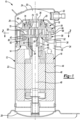
Figure 1 is a cross-sectional view of a compressor having an Oldham coupling according to an example useful for understanding the claimed invention; -
Figure 2 is a cross-sectional view of the compressor taken along line 2-2 ofFigure 1 ; -
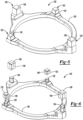
Figure 3 is a perspective view of the Oldham coupling of the compressor ofFigure 1 ; -
Figure 4 is an exploded perspective view of the Oldham coupling ofFigure 3 ; -
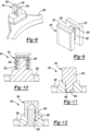
Figure 5 is a perspective view of another Oldham coupling according to an example useful for understanding the claimed invention; -
Figure 6 is an exploded perspective view of the Oldham coupling ofFigure 5 ; -
Figure 7 is a partially exploded perspective view of another Oldham coupling according to an example useful for understanding the claimed invention; -
Figure 8 is a perspective view of a portion of the Oldham coupling ofFigure 7 ; -
Figure 9 is a perspective view of a cap of the Oldham coupling ofFigure 7 ; -
Figure 10 is a partial cross-sectional view of another Oldham coupling according to an example useful for understanding the claimed invention; -
Figure 11 is a partial cross-sectional view of another Oldham coupling according to an example useful for understanding the claimed invention; -
Figure 12 is a partial cross-sectional view of another Oldham coupling according to an example useful for understanding the claimed invention; -
Figure 13 is a partial cross-sectional view of another Oldham coupling according to an example useful for understanding the claimed invention; -
Figure 14 is a partial cross-sectional view of another Oldham coupling according to an example useful for understanding the claimed invention; -
Figure 15 is a partial cross-sectional view of another Oldham coupling according to an example useful for understanding the claimed invention; -
Figure 16 is a perspective view of another Oldham coupling according to an example useful for understanding the claimed invention; -
Figure 17 is an exploded perspective view of the Oldham coupling ofFigure 16 ; -
Figure 18 is a partial cross-sectional view of the Oldham coupling ofFigure 16 ; -
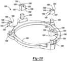
Figure 19 is a perspective view of another Oldham coupling according to the claimed invention and to the principles of the present disclosure; -
Figure 20 is an exploded perspective view of the Oldham coupling ofFigure 19 in a pre-swaged condition; -
Figure 21 is a cross-sectional view of a swaging tool and a portion of the Oldham coupling ofFigure 19 having a post in a pre-swaged condition; -
Figure 22 is a cross-sectional view of the swaging tool being pressed onto the post; -
Figure 23 is a cross-sectional view of the swaging tool being lifted off of the post after the post has been swaged; -
Figure 24 is a partial perspective view of the Oldham coupling ofFigure 19 with the post in a swaged condition; and -
Figure 25 is a perspective view of the swaging tool ofFigures 21-23 . - Corresponding reference numerals indicate corresponding parts throughout the several views of the drawings.
- Example embodiments will now be described more fully with reference to the accompanying drawings.
- With reference to
Figure 1 , acompressor 10 is provided according to an example useful for understanding the claimed invention that may include ahermetic shell assembly 12, abearing housing assembly 14, amotor assembly 16, acompression mechanism 18, and aseal assembly 20. Theshell assembly 12 may generally form a compressor housing and may include acylindrical shell 22, anend cap 24 at the upper end thereof, a transversely extendingpartition 26, and abase 28 at a lower end thereof. Theend cap 24 andpartition 26 may generally define adischarge chamber 30. Adischarge fitting 32 may be attached to theshell assembly 12 at an opening in theend cap 24. A suction gas inlet fitting 34 may be attached to theshell assembly 12 at another opening and may communicate with asuction chamber 35 defined by theshell 22 and thepartition 26. Thepartition 26 may include adischarge passage 36 therethrough providing communication between thecompression mechanism 18 and thedischarge chamber 30. - The bearing
housing assembly 14 may be affixed to theshell 22 and may include a main bearinghousing 38 and abearing 40. The main bearinghousing 38 may house the bearing 40 therein and may define an annular flatthrust bearing surface 42 on an axial end surface thereof. - The
motor assembly 16 may include amotor stator 44, arotor 46, and adriveshaft 48. Themotor stator 44 may be press fit into theshell 22. Thedriveshaft 48 may be rotatably driven by therotor 46 and may be rotatably supported within thebearing 40. Therotor 46 may be press fit on thedriveshaft 48. Thedriveshaft 48 may include aneccentric crankpin 50. - The
compression mechanism 18 may generally include anorbiting scroll 52, anon-orbiting scroll 54 and anOldham coupling 56. The orbitingscroll 52 may include anend plate 58 having aspiral wrap 60 on the upper surface thereof and an annularflat thrust surface 62 on the lower surface. Thethrust surface 62 may interface with the annular flatthrust bearing surface 42 on themain bearing housing 38. Acylindrical hub 64 may project downwardly from thethrust surface 62 and may have adrive bushing 66 rotatably disposed therein. Thedrive bushing 66 may include an inner bore in which thecrank pin 50 is drivingly disposed. A flat surface of thecrankpin 50 may drivingly engage a flat surface in a portion of the inner bore of thedrive bushing 66 to provide a radially compliant driving arrangement. TheOldham coupling 56 may be engaged with the orbiting andnon-orbiting scrolls scroll 52 and themain bearing housing 38 to prevent relative rotation therebetween. - The
non-orbiting scroll 54 may include anend plate 68 and aspiral wrap 70 projecting downwardly from theend plate 68. Thespiral wrap 70 may meshingly engage the spiral wrap 60 of the orbitingscroll 52, thereby creating a series of moving fluid pockets. The fluid pockets defined by the spiral wraps 60, 70 may decrease in volume as they move from a radially outer position (at a suction pressure) to a radially intermediate position (at an intermediate pressure) to a radially inner position (at a discharge pressure) throughout a compression cycle of thecompression mechanism 18. - The
end plate 68 may include a discharge passage 72, anintermediate passage 74, and anannular recess 76. The discharge passage 72 is in communication with one of the fluid pockets at the radially inner position and allows compressed working fluid (e.g., at the discharge pressure) to flow into thedischarge chamber 30. Theintermediate passage 74 may provide communication between one of the fluid pockets at the radially intermediate position and theannular recess 76. Theannular recess 76 may receive theseal assembly 20 and cooperate with theseal assembly 20 to define anaxial biasing chamber 78 therebetween. The biasingchamber 78 receives fluid from the fluid pocket in the intermediate position through theintermediate passage 74. A pressure differential between the intermediate-pressure fluid in the biasingchamber 78 and fluid in thesuction chamber 35 exerts an axial biasing force on thenon-orbiting scroll 54 urging thenon-orbiting scroll 54 toward the orbitingscroll 52 to sealingly engage thescrolls - As shown in
Figures 3 and 4 , theOldham coupling 56 may be a generally ring-shaped member having anannular body 80, a plurality offirst keys 82 and a plurality ofsecond keys 84. As shown inFigure 1 , thebody 80 may be supported by themain bearing housing 38 to allow thebody 80 to be slidably movable thereon. The first andsecond keys body 80 in an axial direction (i.e., in a direction parallel to a rotational axis of the driveshaft 48). As shown inFigure 2 , thefirst keys 82 may slidably engage slots (keyways) 86 formed in theend plate 58 of the orbitingscroll 52, and thesecond keys 84 may slidably engage slots (keyways) 88 formed in theend plate 68 of thenon-orbiting scroll 54. In this manner, theOldham coupling 56 prevents rotation of the orbitingscroll 52 relative to thenon-orbiting scroll 54 while allowing orbital movement of the orbitingscroll 52 relative to thenon-orbiting scroll 54. - While the first and
second keys first keys 82 may extend away from thebody 80 in a direction opposite a direction from which thesecond keys 84 extend away from thebody 80. Further, in some configurations, thesecond keys 84 may slidably engage slots formed in themain bearing housing 38 instead of theslots 88 in thenon-orbiting scroll 54. - As shown in
Figures 3 and 4 , each of thefirst keys 82 may include apost 90 and a cap (or insert) 92, and each of thesecond keys 84 may include apost 94 and a cap (or insert) 96. Theposts body 80 from a first material (e.g., aluminum, iron, steel or another metal or composite). For example, thebody 80 andposts - The
caps posts caps - Each of the
caps aperture 98 that extends entirely through thecap posts posts apertures 98 or only partially through theapertures 98. Theposts apertures 98, adhesively bonded therein, secured with fasteners and/or otherwise securely attached. - With the
caps posts keys keys slots caps posts keys slots caps caps Oldham coupling 56 and present damage to theOldham coupling 56. This structure of thekeys keys - In some configurations, inserts (not shown) formed from the second material could be fixedly received in the
slots keys keys scrolls - Referring now to
Figures 5 and 6 , anotherOldham coupling 156 is provided according to an example useful for understanding the claimed invention that can be incorporated into thecompressor 10 instead of theOldham coupling 56. The structure and function of theOldham coupling 156 can be similar or identical to that of theOldham coupling 56, apart from the differences described below and/or shown in the figures. - As described above with respect to the
Oldham coupling 56, theOldham coupling 156 may include a generallyannular body 180, a plurality offirst keys 182 and a plurality ofsecond keys 184. Like thekeys keys posts posts body 180 may be formed from a first material, and thecaps caps apertures 198 extending partially therethrough and receiving theposts posts apertures 198. Theposts apertures 198, adhesively bonded therein, secured with fasteners and/or otherwise securely attached. - Referring now to
Figures 7-9 , anotherOldham coupling 256 is provided according to an example useful for understanding the claimed invention that can be incorporated into thecompressor 10 instead of theOldham coupling 56. The structure and function of theOldham coupling 256 can be similar or identical to that of theOldham coupling 56, apart from the differences described below and/or shown in the figures. - As described above with respect to the
Oldham coupling 56, theOldham coupling 256 may include a generallyannular body 280, a plurality offirst keys 282 and a plurality ofsecond keys 284. Thekeys posts posts body 280 may be formed from a first material, and thecaps - As shown in
Figures 7 and8 , each of theposts protrusions 293 defining a channel or slot 295 therebetween such that theposts Figures 7 and9 , thecaps blocks 297 and acrossmember 299 extending between and interconnecting theblocks 297. Thecrossmember 299 and blocks 297 form a pair of channels orslots 298. When thecaps posts protrusions 293 of theposts slots 298 of thecaps cross-members 299 of thecaps slots 295 of theposts caps posts Figure 7 , distal edges of thecaps body 280 that the distal edges of theposts posts scrolls - Referring now to
Figure 10 , another Oldham coupling 356 (only partially shown inFigure 10 ) is provided according to an example useful for understanding the claimed invention that can be incorporated into thecompressor 10 instead of theOldham coupling 56. The structure and function of theOldham coupling 356 can be similar or identical to that of theOldham coupling 56, apart from the differences described below and/or shown in the figures. - As described above with respect to the
Oldham coupling 56, theOldham coupling 356 may include a generallyannular body 380 and a plurality ofkeys 382. Thekeys 382 may includeposts 390 and caps 392. Theposts 390 andbody 380 may be formed from a first material, and thecaps 392 may be formed from a second material, as described above. Thecaps 392 may includeapertures 398 that extend partially or entirely therethrough and receive theposts 390. Theapertures 398 may be sufficiently larger in size than theposts 390 to allow thecaps 392 to move radially (i.e., in directions perpendicular to the rotational axis of the driveshaft 48) relative to theposts 390 when theposts 390 are received within theapertures 398. Adhesive and/or other fasteners could be used to attach theposts 390 to thecaps 392. - Referring now to
Figure 11 , another Oldham coupling 456 (only partially shown inFigure 11 ) is provided according to an example useful for understanding the claimed invention that can be incorporated into thecompressor 10 instead of theOldham coupling 56. The structure and function of theOldham coupling 456 can be similar or identical to that of theOldham coupling 56, apart from the differences described below and/or shown in the figures. - As described above with respect to the
Oldham coupling 56, theOldham coupling 456 may include a generallyannular body 480 and a plurality ofkeys 482. Thekeys 482 may includeposts 490 and caps 492. Eachpost 490 may be integrally formed with a corresponding one of thecaps 492 and may threadably engageapertures 498 formed in thebody 480. Thebody 480 may be formed from a first material, and theposts 490 and caps 492 may be formed from a second material. - Referring now to
Figure 12 , another Oldham coupling 556 (only partially shown inFigure 12 ) is provided according to an example useful for understanding the claimed invention that can be incorporated into thecompressor 10 instead of theOldham coupling 56. The structure and function of theOldham coupling 556 can be similar or identical to that of theOldham coupling 56, apart from the differences described below and/or shown in the figures. - As described above with respect to the
Oldham coupling 56, theOldham coupling 556 may include a generallyannular body 580 and a plurality of keys (caps) 582. Thekeys 582 may include threadedapertures 584 that are aligned withapertures 586 in thebody 580. Threadedfasteners 590 may extend throughcorresponding apertures 586 in thebody 580 and threadably engage correspondingapertures 584 in thekeys 582. Thebody 580 may be formed from a first material, and thekeys 582 may be formed from a second material. - Referring now to
Figure 13 , another Oldham coupling 656 (only partially shown inFigure 13 ) is provided according to an example useful for understanding the claimed invention that can be incorporated into thecompressor 10 instead of theOldham coupling 56. The structure and function of theOldham coupling 656 can be similar or identical to that of theOldham coupling 56, apart from the differences described below and/or shown in the figures. - As described above with respect to the
Oldham coupling 56, theOldham coupling 656 may include a generallyannular body 680 and a plurality of keys (caps) 682. Thekeys 682 may includeapertures 684 that are aligned withapertures 686 in thebody 680. Roll pins 690 may be pressed into correspondingapertures pins 690 are compressed when received in theapertures keys 682 to thebody 680. Thebody 680 may be formed from a first material, and thekeys 682 may be formed from a second material. - Referring now to
Figure 14 , another Oldham coupling 756 (only partially shown inFigure 14 ) is provided according to an example useful for understanding the claimed invention that can be incorporated into thecompressor 10 instead of theOldham coupling 56. The structure and function of theOldham coupling 756 can be similar or identical to that of theOldham coupling 56, apart from the differences described below and/or shown in the figures. - As described above with respect to the
Oldham coupling 56, theOldham coupling 756 may include a generallyannular body 780 and a plurality ofkeys 782. Each of thekeys 782 may include apost 790 and a pair ofcaps 792. Theposts 790 may be integrally formed with thebody 780 from a first material. - The
caps 792 may be formed from a second material and may each include a main body 793 (e.g., a rectangular block) and a plurality of protrusions 795 (e.g., cylindrical or rectangular protrusions) extending from themain body 793. Eachpost 790 may be sandwiched between twocaps 792. Theprotrusions 795 of eachcap 792 may be embedded in acorresponding post 790. In some configurations, theposts 790 andbody 780 may be cast with thecaps 792 placed in the casting mold such that theposts 790 are cast around the protrusions 795 (so as to embed theprotrusions 795 inside of the posts 790). In this manner, thecaps 792 are fixedly secured to theposts 790. - It will be appreciated that the
protrusions 795 can be arranged on themain body 793 of thecap 792 in any suitable manner. For example, theprotrusions 795 on eachcap 792 can be arranged in a linear pattern, a staggered pattern, or in a triangular pattern. - Referring now to
Figure 15 , another Oldham coupling 856 (only partially shown inFigure 15 ) is provided according to an example useful for understanding the claimed invention that can be incorporated into thecompressor 10 instead of theOldham coupling 56. The structure and function of theOldham coupling 856 can be similar or identical to that of theOldham coupling 756, apart from the differences described below and/or shown in the figures. - As described above, the
Oldham coupling 856 may include a generallyannular body 880 and a plurality ofkeys 882. Each of thekeys 882 may include an integrally formedpost 890 andcap 892. Thebody 880 may be formed from a first material, and thekeys 882 may be formed from a second material. Thecap 892 may be a rectangular or cubical block, for example. Thepost 890 may be a rectangular block having a plurality of protrusions 895 (e.g., cylindrical or rectangular protrusions) extending therefrom. In some configurations, thebody 880 may be cast with thecaps 892 placed in the casting mold such that thebody 880 is are cast around the posts 890 (so as to embed theposts 890 andprotrusions 895 inside of the body 880). In this manner, thecaps 892 are fixedly secured to thebody 880. - It will be appreciated that additional or alternative means could be utilized to attach the caps or keys to the body of any of the Oldham couplings 56, 156, 256, 356, 456, 556, 656, 756, 856. Such additional or alternative attaching means could include swaging, welding, brazing, shrink fitting, crimping, or snap fitting, for example.
- Referring now to
Figures 16-18 , anotherOldham coupling 956 is provided according to an example useful for understanding the claimed invention that can be incorporated into thecompressor 10 instead of theOldham coupling 56. The structure and function of theOldham coupling 956 can be similar or identical to that of theOldham coupling 56, apart from the differences described below and/or shown in the figures. - As described above with respect to the
Oldham coupling 56, theOldham coupling 956 may include a generallyannular body 980, a plurality offirst keys 982 and a plurality ofsecond keys 984. Like thekeys keys posts posts body 980 may be formed from a first material, and thecaps caps posts posts - As shown in
Figures 17 and18 , a distal end 950 (i.e., an end spaced apart from the body 980) of each of theposts second flanges second grooves first flange 952 of eachpost side 960 of thepost second flange 954 of eachpost side 962 of thepost sides body 980 to thedistal end 950. Thefirst grooves 957 may be formed in the inwardly facingsides 960 directly adjacent thefirst flanges 952 and between thebody 980 and thefirst flanges 952. Thesecond grooves 958 may be formed in the outwardly facingsides 962 directly adjacent thesecond flanges 954 and between thebody 980 and thesecond flanges 954. As shown inFigure 18 , the first andsecond flanges posts second flanges main body 964 of thepost - Each of the
caps aperture 998 that extends entirely through thecap posts posts apertures 998 or only partially through theapertures 998. As shown inFigure 18 , each of theapertures 998 includes a counterbore orrecess 970 at one axial end and a countersink orchamfer 972 at the other axial end. - A portion of the
aperture 998 disposed axially between therecess 970 and thechamfer 972 may have a width that is equal to or slightly larger than the width W1 of themain body 964 of thecorresponding post second flanges corresponding post recess 970 has a width W2 that is larger than the distance D. - The
caps posts caps posts distal end 950 of eachpost aperture 998 that has thechamber 972. Thechamfer 972 facilitates the initial insertion of thepost aperture 998. Theflanges grooves aperture 998 may expand as theflanges aperture 998 between thechamfer 972 and therecess 970. Once theflanges end surface 974 of therecess 970, thedeformed flanges aperture 998 may snap back to their original shape(s). Then, with theflanges aperture 998 back in their original shape(s), interference between theflanges end surface 974 of the recess prevents thecap post caps posts posts apertures 998 can be done with a relatively light amount of force (e.g., 0.1-0.3 kN of force) and without any special tooling. - While
Figure 18 shows a portion of thedistal end 950 of thepost aperture 998, in some configurations, theentire post aperture 998 when thecap post 990, 994 (i.e., the entiredistal end 950 may be received within the recess 970). - Referring now to
Figures 19-25 , anOldham coupling 1056 according to the invention is provided that is incorporated into thecompressor 10 instead of theOldham coupling 56. The structure and function of theOldham coupling 1056 can be similar or identical to that of theOldham coupling 56, apart from the differences described below and/or shown in the figures. - As described above with respect to the
Oldham coupling 56, theOldham coupling 1056 includes a generallyannular body 1080, a plurality offirst keys 1082 and a plurality ofsecond keys 1084. Like thekeys keys posts posts body 1080 are formed from a first material, and thecaps caps posts posts - As shown in
Figure 20 , each of thecaps aperture 1098 extending entirely therethrough. That is, theaperture 1098 extends through aproximal end 1097 of thecap 1092, 1096 (i.e., the end adjacent the body 1080) and adistal end 1099 of thecap 1092, 1096 (i.e., the end furthest from the body 1080). Thedistal end 1099 of eachcap groove 1050 formed therein that intersects the aperture 1098 (i.e., extends laterally outward from opposite sides of the aperture 1098) and extends laterally through opposingsides cap Figures 21-23 , theaperture 1098 may include a chamfer (similar to chamfer 972) at theproximal end 1097 of thecap posts caps - As shown in
Figures 20 and21 , theposts posts caps posts Figure 21 . Thereafter, aswaging tool 1100 can be used to swage or deform adistal end 1091 of each of theposts Figures 22 and 23 . - As shown in
Figure 25 , theswaging tool 1100 may include acavity 1110 and arib 1112 disposed within thecavity 1110. A length L of thecavity 1110 and a width W of thecavity 1110 may be at least slightly larger than the length and width of thecaps distal end 1099 of thecaps cavity 1110. Therib 1112 has a thickness T that is slightly smaller than a thickness of thegrooves 1050 in thecaps rib 1112 can be received in thegrooves 1050 while thedistal end 1099 of thecaps cavity 1110. As shown inFigures 21-24 , therib 1112 may include a generally V-shapedcentral recess 1114 disposed between a pair ofsteps 1116. The spacing between thesteps 1116 is such that theposts steps 1116. - As described above and shown in
Figure 21 , thecaps posts posts posts 1090, 1094). Thereafter, theswaging tool 1100 can be placed over thedistal end 1099 of thecap distal end 1091 of thepost steps 1116 of therib 1112, as shown inFigure 22 . Thereafter, a downward force can be applied to theswaging tool 1100 to press therib 1112 into thedistal end 1091 of thepost notches 1075 and flanges 1077 (shown inFigures 23 and24 ) in thepost flanges 1077 is greater than the width of theaperture 1098 such that theflanges 1077 interfere withend walls 1079 of thegroove 1050 in thecap cap post - The
compressor 10 described above and shown in the figures is provided as an example of a compressor in which the Oldham couplings of the present disclosure may be incorporated. It will be appreciated that the teachings of the present disclosure can be incorporated into any type or configuration of scroll compressor.
Claims (7)
- A compressor (10) comprising:a non-orbiting scroll (54);an orbiting scroll (52) meshingly engaged with the non-orbiting scroll;a driveshaft (48) having a crankpin (50) engaging the orbiting scroll and driving the orbiting scroll in an orbital path relative to the non-orbiting scroll; andan Oldham coupling (1056) including an annular body (1080) and a plurality of keys (1082, 1084) extending from the annular body and slidably received in slots (86, 88) formed in the orbiting scroll, the annular body formed from a first material, the keys are attached to the annular body, wherein each of the keys (1082, 1084) includes a post (1090, 1094) and a cap (1092, 1096), wherein the posts (1090, 1094) are integrally formed with the annular body (1080), wherein the caps (1092, 1096) are formed from a second material, wherein each cap (1092, 1096) includes an aperture (1098) extending entirely through the cap (1090, 1094) and receiving one of the posts (1090, 1094),characterized in that the caps (1092, 1096) are fixed to the posts (1090, 1094) by deformations formed on the posts, wherein each of the caps (1092, 1096) includes a pair of grooves (1050), and wherein the grooves (1050) receive the deformations formed on the posts (1090, 1094).
- The compressor of claim 1, wherein the caps are all discrete components that are non-integrally formed.
- The compressor of either of claims 1 or 2, wherein the first material is a metal and the second material includes a polymer.
- The compressor of either of claims 1 or 2, wherein the first material is a first metal and the second material includes a second metal.
- The compressor of any of the preceding claims, wherein the caps are attached to the body by swaging.
- The compressor of any of the preceding claims, wherein each of the grooves (1050) extends laterally through opposing sides (1052, 1054) of the cap (1092, 1096).
- The compressor of any of the preceding claims, wherein the grooves (1050) are open to the aperture (1098) and extend through a distal end of the cap (1092, 1096).
Applications Claiming Priority (2)
| Application Number | Priority Date | Filing Date | Title |
|---|---|---|---|
| US201662296229P | 2016-02-17 | 2016-02-17 | |
| US15/252,579 US10400770B2 (en) | 2016-02-17 | 2016-08-31 | Compressor with Oldham assembly |
Publications (2)
| Publication Number | Publication Date |
|---|---|
| EP3208417A1 EP3208417A1 (en) | 2017-08-23 |
| EP3208417B1 true EP3208417B1 (en) | 2025-01-08 |
Family
ID=58054018
Family Applications (1)
| Application Number | Title | Priority Date | Filing Date |
|---|---|---|---|
| EP17156102.0A Active EP3208417B1 (en) | 2016-02-17 | 2017-02-14 | Compressor with oldham assembly |
Country Status (3)
| Country | Link |
|---|---|
| US (2) | US10400770B2 (en) |
| EP (1) | EP3208417B1 (en) |
| CN (2) | CN206668549U (en) |
Families Citing this family (22)
| Publication number | Priority date | Publication date | Assignee | Title |
|---|---|---|---|---|
| US10400770B2 (en) | 2016-02-17 | 2019-09-03 | Emerson Climate Technologies, Inc. | Compressor with Oldham assembly |
| US11111921B2 (en) | 2017-02-06 | 2021-09-07 | Emerson Climate Technologies, Inc. | Co-rotating compressor |
| KR20190085407A (en) | 2018-01-10 | 2019-07-18 | 엘지전자 주식회사 | Scroll compressor |
| US20190277289A1 (en) | 2018-03-12 | 2019-09-12 | Lg Electronics Inc. | Scroll compressor |
| KR102043155B1 (en) | 2018-05-09 | 2019-11-11 | 엘지전자 주식회사 | Scroll compressor |
| KR102081341B1 (en) | 2018-08-31 | 2020-02-25 | 엘지전자 주식회사 | Scroll compressor |
| EP3567212B1 (en) * | 2018-05-10 | 2024-01-17 | Lg Electronics Inc. | Compressor having oldham's ring |
| KR20200030390A (en) | 2018-09-12 | 2020-03-20 | 엘지전자 주식회사 | Motor operated compressor |
| US11136977B2 (en) | 2018-12-31 | 2021-10-05 | Emerson Climate Technologies, Inc. | Compressor having Oldham keys |
| KR102202335B1 (en) | 2019-02-14 | 2021-01-13 | 엘지전자 주식회사 | A compressor |
| JP7208364B2 (en) * | 2019-04-19 | 2023-01-18 | 三菱重工サーマルシステムズ株式会社 | scroll compressor |
| EP4058675B1 (en) | 2019-11-15 | 2025-12-31 | Copeland LP | Rotating spiral compressor |
| KR102364680B1 (en) | 2020-02-10 | 2022-02-18 | 엘지전자 주식회사 | A compressor |
| KR102422699B1 (en) * | 2020-12-29 | 2022-07-20 | 엘지전자 주식회사 | Scroll compressor |
| KR102510338B1 (en) | 2021-09-13 | 2023-03-15 | 엘지전자 주식회사 | Scroll compressor |
| KR102586750B1 (en) | 2021-09-13 | 2023-10-11 | 엘지전자 주식회사 | Scroll compressor |
| US11732713B2 (en) | 2021-11-05 | 2023-08-22 | Emerson Climate Technologies, Inc. | Co-rotating scroll compressor having synchronization mechanism |
| US12104594B2 (en) | 2021-11-05 | 2024-10-01 | Copeland Lp | Co-rotating compressor |
| US11624366B1 (en) | 2021-11-05 | 2023-04-11 | Emerson Climate Technologies, Inc. | Co-rotating scroll compressor having first and second Oldham couplings |
| JP7393680B2 (en) | 2022-02-22 | 2023-12-07 | ダイキン工業株式会社 | Refrigeration cycle equipment |
| WO2024055833A1 (en) * | 2022-09-16 | 2024-03-21 | 谷轮环境科技(苏州)有限公司 | Cross slip ring assembly of scroll compressor and scroll compressor |
| KR102824017B1 (en) * | 2023-05-15 | 2025-06-23 | 엘지전자 주식회사 | Scroll compressor |
Family Cites Families (74)
| Publication number | Priority date | Publication date | Assignee | Title |
|---|---|---|---|---|
| US587063A (en) * | 1897-07-27 | peaesall | ||
| US688579A (en) * | 1901-04-22 | 1901-12-10 | Edwin Drew Bartlett | Magazine film-holder. |
| US4121438A (en) * | 1976-09-13 | 1978-10-24 | Arthur D. Little, Inc. | Coupling member for orbiting machinery |
| US4330392A (en) * | 1980-08-29 | 1982-05-18 | Exxon Research & Engineering Co. | Hydroconversion process |
| US4992033A (en) | 1986-08-22 | 1991-02-12 | Copeland Corporation | Scroll-type machine having compact Oldham coupling |
| US5219281A (en) | 1986-08-22 | 1993-06-15 | Copeland Corporation | Fluid compressor with liquid separating baffle overlying the inlet port |
| US5407335A (en) | 1986-08-22 | 1995-04-18 | Copeland Corporation | Non-orbiting scroll mounting arrangements for a scroll machine |
| US4877382A (en) | 1986-08-22 | 1989-10-31 | Copeland Corporation | Scroll-type machine with axially compliant mounting |
| JPH0689750B2 (en) | 1986-09-30 | 1994-11-14 | 三井精機工業株式会社 | Oldham joint structure of scroll compressor |
| JP2758193B2 (en) | 1989-02-28 | 1998-05-28 | 株式会社東芝 | Scroll fluid machinery and Oldham couplings for scroll fluid machinery |
| DE69103604T2 (en) | 1990-10-01 | 1994-12-22 | Copeland Corp | Oldham's clutch for scroll compressors. |
| JPH04330392A (en) * | 1991-04-26 | 1992-11-18 | Riken Corp | Scroll compressor |
| JPH0579474A (en) * | 1991-09-17 | 1993-03-30 | Daido Metal Co Ltd | Oldham ring for scroll type compressor and manufacture thereof |
| JPH0587063A (en) | 1991-09-26 | 1993-04-06 | Riken Corp | Scroll compressor |
| US5141417A (en) | 1991-12-17 | 1992-08-25 | Carrier Corporation | Method for dynamically balancing nested coupling mechanisms for scroll machines |
| US5141421A (en) | 1991-12-17 | 1992-08-25 | Carrier Corporation | Nested coupling mechanism for scroll machines |
| JP3061469B2 (en) * | 1992-02-14 | 2000-07-10 | 東芝キヤリア株式会社 | Scroll type compressor |
| JPH0610853A (en) | 1992-06-30 | 1994-01-21 | Mitsubishi Electric Corp | Scroll compressor |
| JPH0688579A (en) * | 1992-09-08 | 1994-03-29 | Toshiba Corp | Oldham's ring of scroll type compressor, etc. |
| JP2682784B2 (en) | 1993-02-23 | 1997-11-26 | 大同メタル工業株式会社 | Oldham ring of scroll type compressor |
| US5330334A (en) | 1993-08-26 | 1994-07-19 | Carrier Corporation | Compact Oldham coupling |
| US5403172A (en) | 1993-11-03 | 1995-04-04 | Copeland Corporation | Scroll machine sound attenuation |
| JPH08319958A (en) | 1995-05-24 | 1996-12-03 | Sanden Corp | Scroll type fluid device |
| US5582512A (en) | 1995-07-07 | 1996-12-10 | Carrier Corporation | Compact oldham coupling |
| JPH09112448A (en) | 1995-10-18 | 1997-05-02 | Matsushita Electric Ind Co Ltd | Scroll compressor |
| US5897306A (en) | 1997-04-17 | 1999-04-27 | Copeland Corporation | Partition and pilot ring for scroll machine |
| JPH11173282A (en) | 1997-12-12 | 1999-06-29 | Hitachi Ltd | Scroll compressor |
| JP3918277B2 (en) | 1998-02-20 | 2007-05-23 | 株式会社日立製作所 | Scroll compressor |
| US6146118A (en) | 1998-06-22 | 2000-11-14 | Tecumseh Products Company | Oldham coupling for a scroll compressor |
| JP2000337272A (en) * | 1999-05-24 | 2000-12-05 | Hitachi Ltd | Oldham ring of scroll compressor |
| US6231324B1 (en) | 2000-02-02 | 2001-05-15 | Copeland Corporation | Oldham coupling for scroll machine |
| KR100393798B1 (en) | 2001-05-03 | 2003-08-02 | 엘지전자 주식회사 | Oldham's coupling structure for scroll compressor |
| US6439867B1 (en) | 2001-05-14 | 2002-08-27 | Copeland Corporation | Scroll compressor having a clearance for the oldham coupling |
| US6546816B2 (en) | 2001-08-31 | 2003-04-15 | Cts Corporation | Eccentricity compensator with low hysteresis for use between two non-coaxial rotating shafts |
| JP2004190605A (en) | 2002-12-12 | 2004-07-08 | Toshiba Kyaria Kk | Fluid machinery |
| KR100621001B1 (en) | 2004-10-07 | 2006-09-19 | 엘지전자 주식회사 | Scroll compressor |
| FR2885967B1 (en) | 2005-05-23 | 2007-12-21 | Danfoss Commercial Compressors | CONNECTION ELEMENT BETWEEN THE TWO VOLUME OF A SPIRAL COMPRESSOR |
| JP4850177B2 (en) | 2005-06-29 | 2012-01-11 | 株式会社ケーヒン | Scroll compressor |
| KR100672283B1 (en) | 2006-06-23 | 2007-01-24 | 학교법인 두원학원 | Scroll compressors with anti-rotation mechanism |
| US7371059B2 (en) | 2006-09-15 | 2008-05-13 | Emerson Climate Technologies, Inc. | Scroll compressor with discharge valve |
| US8241022B2 (en) | 2006-09-21 | 2012-08-14 | Daikin Industries, Ltd. | Rotation-preventing member and scroll compressor |
| US20080085204A1 (en) | 2006-10-06 | 2008-04-10 | Scroll Technologies | Scroll compressor with titanium Oldham coupling |
| JP5008374B2 (en) | 2006-10-18 | 2012-08-22 | サンデン株式会社 | Scroll compressor |
| US20080119294A1 (en) | 2006-11-16 | 2008-05-22 | Erikson Kenneth W | Oldham Coupling with Damping |
| US7717687B2 (en) | 2007-03-23 | 2010-05-18 | Emerson Climate Technologies, Inc. | Scroll compressor with compliant retainer |
| US8262377B2 (en) | 2007-04-04 | 2012-09-11 | Emerson Climate Technologies, Inc. | Injection molded scroll form |
| US7914268B2 (en) | 2007-09-11 | 2011-03-29 | Emerson Climate Technologies, Inc. | Compressor having shell with alignment features |
| US8057202B2 (en) | 2007-10-23 | 2011-11-15 | Tecumseh Products Company | Tip seal for a scroll compressor |
| JP5150206B2 (en) | 2007-10-31 | 2013-02-20 | 株式会社日立産機システム | Scroll type fluid machine |
| US7918658B2 (en) | 2008-01-17 | 2011-04-05 | Bitzer Scroll Inc. | Non symmetrical key coupling contact and scroll compressor having same |
| JP2009264370A (en) | 2008-03-31 | 2009-11-12 | Hitachi Ltd | Scroll type fluid machine |
| US8177534B2 (en) | 2008-10-30 | 2012-05-15 | Advanced Scroll Technologies (Hangzhou), Inc. | Scroll-type fluid displacement apparatus with improved cooling system |
| JP5253224B2 (en) | 2009-02-20 | 2013-07-31 | 三洋電機株式会社 | Scroll compressor |
| FR2947308B1 (en) | 2009-06-30 | 2014-04-18 | Danfoss Commercial Compressors | MULTI-STAGE VOLUME MACHINE |
| US8287257B2 (en) * | 2009-08-21 | 2012-10-16 | Thermo King Corporation | Oldham coupling |
| JP5352384B2 (en) | 2009-08-31 | 2013-11-27 | 株式会社日立産機システム | Scroll type fluid machine |
| KR101308776B1 (en) | 2010-11-08 | 2013-09-17 | 다이킨 고교 가부시키가이샤 | Scroll compressor |
| FR2969226B1 (en) | 2010-12-16 | 2013-01-11 | Danfoss Commercial Compressors | SPIRAL REFRIGERATING COMPRESSOR |
| EP2655835B1 (en) | 2010-12-20 | 2017-05-17 | Continental Automotive GmbH | Valve unit |
| US9022758B2 (en) | 2012-03-23 | 2015-05-05 | Bitzer Kuehlmaschinenbau Gmbh | Floating scroll seal with retaining ring |
| US9181949B2 (en) | 2012-03-23 | 2015-11-10 | Bitzer Kuehlmaschinenbau Gmbh | Compressor with oil return passage formed between motor and shell |
| US9347441B2 (en) | 2012-03-30 | 2016-05-24 | Sabic Global Technologies B.V. | Compressors including polymeric components |
| JP5925578B2 (en) | 2012-04-25 | 2016-05-25 | アネスト岩田株式会社 | Scroll expander |
| JP5464248B1 (en) | 2012-09-27 | 2014-04-09 | ダイキン工業株式会社 | Scroll compressor |
| US9249802B2 (en) | 2012-11-15 | 2016-02-02 | Emerson Climate Technologies, Inc. | Compressor |
| FR3000144B1 (en) | 2012-12-21 | 2018-11-16 | Danfoss Commercial Compressors | SPIRAL COMPRESSOR HAVING OLDHAM FIRST AND SECOND JOINTS |
| JP6171601B2 (en) | 2013-06-12 | 2017-08-02 | 株式会社豊田自動織機 | Rotation prevention mechanism of scroll compressor |
| US9765784B2 (en) | 2013-07-31 | 2017-09-19 | Trane International Inc. | Oldham coupling with enhanced key surface in a scroll compressor |
| FR3011592B1 (en) | 2013-10-08 | 2018-02-02 | Danfoss Commercial Compressors | Spiral compressor |
| US9797401B2 (en) | 2013-12-09 | 2017-10-24 | Mitsubishi Electric Corporation | Scroll compressor |
| US9638036B2 (en) | 2014-10-31 | 2017-05-02 | Emerson Climate Technologies, Inc. | Scroll compressor including oldham coupling having keys that are slidingly received in slots of a non-orbiting scroll and/or an orbiting scroll |
| KR101718045B1 (en) | 2015-09-07 | 2017-03-20 | 엘지전자 주식회사 | Scroll compressor |
| US10400770B2 (en) | 2016-02-17 | 2019-09-03 | Emerson Climate Technologies, Inc. | Compressor with Oldham assembly |
| US11136977B2 (en) | 2018-12-31 | 2021-10-05 | Emerson Climate Technologies, Inc. | Compressor having Oldham keys |
-
2016
- 2016-08-31 US US15/252,579 patent/US10400770B2/en active Active
-
2017
- 2017-02-14 EP EP17156102.0A patent/EP3208417B1/en active Active
- 2017-02-16 CN CN201720140411.XU patent/CN206668549U/en active Active
- 2017-02-16 CN CN201710083894.9A patent/CN107091229B/en active Active
-
2019
- 2019-08-29 US US16/555,413 patent/US11002275B2/en active Active
Also Published As
| Publication number | Publication date |
|---|---|
| US10400770B2 (en) | 2019-09-03 |
| CN107091229B (en) | 2020-03-24 |
| CN107091229A (en) | 2017-08-25 |
| US11002275B2 (en) | 2021-05-11 |
| US20170234313A1 (en) | 2017-08-17 |
| EP3208417A1 (en) | 2017-08-23 |
| CN206668549U (en) | 2017-11-24 |
| US20190383289A1 (en) | 2019-12-19 |
Similar Documents
| Publication | Publication Date | Title |
|---|---|---|
| US11002275B2 (en) | Compressor with Oldham assembly | |
| US10975868B2 (en) | Compressor with floating seal | |
| US20130177465A1 (en) | Compressor with compliant thrust bearing | |
| US11015598B2 (en) | Compressor having bushing | |
| US11002276B2 (en) | Compressor having bushing | |
| US10215175B2 (en) | Compressor high-side axial seal and seal assembly retainer | |
| US11767838B2 (en) | Compressor having suction fitting | |
| US9605676B2 (en) | Variable speed scroll compressor | |
| EP3947975B1 (en) | Compressor having directed suction | |
| US11136977B2 (en) | Compressor having Oldham keys | |
| EP4675081A1 (en) | Bearing and unloader assembly for compressors | |
| US12078173B2 (en) | Compressor having lubrication system | |
| US11149735B2 (en) | Polymeric composite insert component for a scroll compressor | |
| US20210239113A1 (en) | Compressor Bearing | |
| EP4158199B1 (en) | Compressor with compliant seal | |
| EP4520972A1 (en) | Compressor having shutdown valve assembly | |
| EP4189245B1 (en) | COMPRESSOR WITH SHELL VALVE | |
| US20250052244A1 (en) | Compressor Having Shutdown Valve Assembly | |
| US20210355944A1 (en) | Compressor Having Muffler Plate |
Legal Events
| Date | Code | Title | Description |
|---|---|---|---|
| PUAI | Public reference made under article 153(3) epc to a published international application that has entered the european phase |
Free format text: ORIGINAL CODE: 0009012 |
|
| STAA | Information on the status of an ep patent application or granted ep patent |
Free format text: STATUS: THE APPLICATION HAS BEEN PUBLISHED |
|
| AK | Designated contracting states |
Kind code of ref document: A1 Designated state(s): AL AT BE BG CH CY CZ DE DK EE ES FI FR GB GR HR HU IE IS IT LI LT LU LV MC MK MT NL NO PL PT RO RS SE SI SK SM TR |
|
| AX | Request for extension of the european patent |
Extension state: BA ME |
|
| STAA | Information on the status of an ep patent application or granted ep patent |
Free format text: STATUS: REQUEST FOR EXAMINATION WAS MADE |
|
| 17P | Request for examination filed |
Effective date: 20180221 |
|
| RBV | Designated contracting states (corrected) |
Designated state(s): AL AT BE BG CH CY CZ DE DK EE ES FI FR GB GR HR HU IE IS IT LI LT LU LV MC MK MT NL NO PL PT RO RS SE SI SK SM TR |
|
| STAA | Information on the status of an ep patent application or granted ep patent |
Free format text: STATUS: EXAMINATION IS IN PROGRESS |
|
| 17Q | First examination report despatched |
Effective date: 20200226 |
|
| GRAP | Despatch of communication of intention to grant a patent |
Free format text: ORIGINAL CODE: EPIDOSNIGR1 |
|
| STAA | Information on the status of an ep patent application or granted ep patent |
Free format text: STATUS: GRANT OF PATENT IS INTENDED |
|
| INTG | Intention to grant announced |
Effective date: 20230710 |
|
| GRAJ | Information related to disapproval of communication of intention to grant by the applicant or resumption of examination proceedings by the epo deleted |
Free format text: ORIGINAL CODE: EPIDOSDIGR1 |
|
| STAA | Information on the status of an ep patent application or granted ep patent |
Free format text: STATUS: EXAMINATION IS IN PROGRESS |
|
| INTC | Intention to grant announced (deleted) | ||
| RAP3 | Party data changed (applicant data changed or rights of an application transferred) |
Owner name: COPELAND LP |
|
| GRAP | Despatch of communication of intention to grant a patent |
Free format text: ORIGINAL CODE: EPIDOSNIGR1 |
|
| STAA | Information on the status of an ep patent application or granted ep patent |
Free format text: STATUS: GRANT OF PATENT IS INTENDED |
|
| INTG | Intention to grant announced |
Effective date: 20240729 |
|
| GRAS | Grant fee paid |
Free format text: ORIGINAL CODE: EPIDOSNIGR3 |
|
| GRAA | (expected) grant |
Free format text: ORIGINAL CODE: 0009210 |
|
| STAA | Information on the status of an ep patent application or granted ep patent |
Free format text: STATUS: THE PATENT HAS BEEN GRANTED |
|
| AK | Designated contracting states |
Kind code of ref document: B1 Designated state(s): AL AT BE BG CH CY CZ DE DK EE ES FI FR GB GR HR HU IE IS IT LI LT LU LV MC MK MT NL NO PL PT RO RS SE SI SK SM TR |
|
| REG | Reference to a national code |
Ref country code: GB Ref legal event code: FG4D |
|
| REG | Reference to a national code |
Ref country code: CH Ref legal event code: EP |
|
| REG | Reference to a national code |
Ref country code: DE Ref legal event code: R096 Ref document number: 602017087205 Country of ref document: DE |
|
| REG | Reference to a national code |
Ref country code: IE Ref legal event code: FG4D |
|
| REG | Reference to a national code |
Ref country code: LT Ref legal event code: MG9D |
|
| REG | Reference to a national code |
Ref country code: NL Ref legal event code: MP Effective date: 20250108 |
|
| REG | Reference to a national code |
Ref country code: AT Ref legal event code: MK05 Ref document number: 1758438 Country of ref document: AT Kind code of ref document: T Effective date: 20250108 |
|
| PG25 | Lapsed in a contracting state [announced via postgrant information from national office to epo] |
Ref country code: NL Free format text: LAPSE BECAUSE OF FAILURE TO SUBMIT A TRANSLATION OF THE DESCRIPTION OR TO PAY THE FEE WITHIN THE PRESCRIBED TIME-LIMIT Effective date: 20250108 |
|
| PG25 | Lapsed in a contracting state [announced via postgrant information from national office to epo] |
Ref country code: RS Free format text: LAPSE BECAUSE OF FAILURE TO SUBMIT A TRANSLATION OF THE DESCRIPTION OR TO PAY THE FEE WITHIN THE PRESCRIBED TIME-LIMIT Effective date: 20250408 |
|
| PG25 | Lapsed in a contracting state [announced via postgrant information from national office to epo] |
Ref country code: FI Free format text: LAPSE BECAUSE OF FAILURE TO SUBMIT A TRANSLATION OF THE DESCRIPTION OR TO PAY THE FEE WITHIN THE PRESCRIBED TIME-LIMIT Effective date: 20250108 |
|
| PG25 | Lapsed in a contracting state [announced via postgrant information from national office to epo] |
Ref country code: PL Free format text: LAPSE BECAUSE OF FAILURE TO SUBMIT A TRANSLATION OF THE DESCRIPTION OR TO PAY THE FEE WITHIN THE PRESCRIBED TIME-LIMIT Effective date: 20250108 |
|
| PG25 | Lapsed in a contracting state [announced via postgrant information from national office to epo] |
Ref country code: ES Free format text: LAPSE BECAUSE OF FAILURE TO SUBMIT A TRANSLATION OF THE DESCRIPTION OR TO PAY THE FEE WITHIN THE PRESCRIBED TIME-LIMIT Effective date: 20250108 |
|
| PG25 | Lapsed in a contracting state [announced via postgrant information from national office to epo] |
Ref country code: NO Free format text: LAPSE BECAUSE OF FAILURE TO SUBMIT A TRANSLATION OF THE DESCRIPTION OR TO PAY THE FEE WITHIN THE PRESCRIBED TIME-LIMIT Effective date: 20250408 Ref country code: IS Free format text: LAPSE BECAUSE OF FAILURE TO SUBMIT A TRANSLATION OF THE DESCRIPTION OR TO PAY THE FEE WITHIN THE PRESCRIBED TIME-LIMIT Effective date: 20250508 |
|
| PG25 | Lapsed in a contracting state [announced via postgrant information from national office to epo] |
Ref country code: HR Free format text: LAPSE BECAUSE OF FAILURE TO SUBMIT A TRANSLATION OF THE DESCRIPTION OR TO PAY THE FEE WITHIN THE PRESCRIBED TIME-LIMIT Effective date: 20250108 |
|
| PG25 | Lapsed in a contracting state [announced via postgrant information from national office to epo] |
Ref country code: LV Free format text: LAPSE BECAUSE OF FAILURE TO SUBMIT A TRANSLATION OF THE DESCRIPTION OR TO PAY THE FEE WITHIN THE PRESCRIBED TIME-LIMIT Effective date: 20250108 Ref country code: PT Free format text: LAPSE BECAUSE OF FAILURE TO SUBMIT A TRANSLATION OF THE DESCRIPTION OR TO PAY THE FEE WITHIN THE PRESCRIBED TIME-LIMIT Effective date: 20250508 |
|
| PG25 | Lapsed in a contracting state [announced via postgrant information from national office to epo] |
Ref country code: BG Free format text: LAPSE BECAUSE OF FAILURE TO SUBMIT A TRANSLATION OF THE DESCRIPTION OR TO PAY THE FEE WITHIN THE PRESCRIBED TIME-LIMIT Effective date: 20250108 Ref country code: GR Free format text: LAPSE BECAUSE OF FAILURE TO SUBMIT A TRANSLATION OF THE DESCRIPTION OR TO PAY THE FEE WITHIN THE PRESCRIBED TIME-LIMIT Effective date: 20250409 |
|
| PG25 | Lapsed in a contracting state [announced via postgrant information from national office to epo] |
Ref country code: AT Free format text: LAPSE BECAUSE OF FAILURE TO SUBMIT A TRANSLATION OF THE DESCRIPTION OR TO PAY THE FEE WITHIN THE PRESCRIBED TIME-LIMIT Effective date: 20250108 |
|
| PG25 | Lapsed in a contracting state [announced via postgrant information from national office to epo] |
Ref country code: SE Free format text: LAPSE BECAUSE OF FAILURE TO SUBMIT A TRANSLATION OF THE DESCRIPTION OR TO PAY THE FEE WITHIN THE PRESCRIBED TIME-LIMIT Effective date: 20250108 |
|
| REG | Reference to a national code |
Ref country code: CH Ref legal event code: PL |
|
| PG25 | Lapsed in a contracting state [announced via postgrant information from national office to epo] |
Ref country code: SM Free format text: LAPSE BECAUSE OF FAILURE TO SUBMIT A TRANSLATION OF THE DESCRIPTION OR TO PAY THE FEE WITHIN THE PRESCRIBED TIME-LIMIT Effective date: 20250108 |
|
| REG | Reference to a national code |
Ref country code: DE Ref legal event code: R097 Ref document number: 602017087205 Country of ref document: DE |
|
| PG25 | Lapsed in a contracting state [announced via postgrant information from national office to epo] |
Ref country code: DK Free format text: LAPSE BECAUSE OF FAILURE TO SUBMIT A TRANSLATION OF THE DESCRIPTION OR TO PAY THE FEE WITHIN THE PRESCRIBED TIME-LIMIT Effective date: 20250108 |
|
| PG25 | Lapsed in a contracting state [announced via postgrant information from national office to epo] |
Ref country code: MC Free format text: LAPSE BECAUSE OF FAILURE TO SUBMIT A TRANSLATION OF THE DESCRIPTION OR TO PAY THE FEE WITHIN THE PRESCRIBED TIME-LIMIT Effective date: 20250108 |
|
| PG25 | Lapsed in a contracting state [announced via postgrant information from national office to epo] |
Ref country code: LU Free format text: LAPSE BECAUSE OF NON-PAYMENT OF DUE FEES Effective date: 20250214 |
|
| PG25 | Lapsed in a contracting state [announced via postgrant information from national office to epo] |
Ref country code: CH Free format text: LAPSE BECAUSE OF NON-PAYMENT OF DUE FEES Effective date: 20250228 |
|
| PG25 | Lapsed in a contracting state [announced via postgrant information from national office to epo] |
Ref country code: EE Free format text: LAPSE BECAUSE OF FAILURE TO SUBMIT A TRANSLATION OF THE DESCRIPTION OR TO PAY THE FEE WITHIN THE PRESCRIBED TIME-LIMIT Effective date: 20250108 Ref country code: CZ Free format text: LAPSE BECAUSE OF FAILURE TO SUBMIT A TRANSLATION OF THE DESCRIPTION OR TO PAY THE FEE WITHIN THE PRESCRIBED TIME-LIMIT Effective date: 20250108 |
|
| PG25 | Lapsed in a contracting state [announced via postgrant information from national office to epo] |
Ref country code: RO Free format text: LAPSE BECAUSE OF FAILURE TO SUBMIT A TRANSLATION OF THE DESCRIPTION OR TO PAY THE FEE WITHIN THE PRESCRIBED TIME-LIMIT Effective date: 20250108 |
|
| PG25 | Lapsed in a contracting state [announced via postgrant information from national office to epo] |
Ref country code: SK Free format text: LAPSE BECAUSE OF FAILURE TO SUBMIT A TRANSLATION OF THE DESCRIPTION OR TO PAY THE FEE WITHIN THE PRESCRIBED TIME-LIMIT Effective date: 20250108 |
|
| PLBE | No opposition filed within time limit |
Free format text: ORIGINAL CODE: 0009261 |
|
| STAA | Information on the status of an ep patent application or granted ep patent |
Free format text: STATUS: NO OPPOSITION FILED WITHIN TIME LIMIT |
|
| REG | Reference to a national code |
Ref country code: BE Ref legal event code: MM Effective date: 20250228 |
|
| 26N | No opposition filed |
Effective date: 20251009 |
|
| GBPC | Gb: european patent ceased through non-payment of renewal fee |
Effective date: 20250408 |
|
| PG25 | Lapsed in a contracting state [announced via postgrant information from national office to epo] |
Ref country code: GB Free format text: LAPSE BECAUSE OF NON-PAYMENT OF DUE FEES Effective date: 20250408 |
|
| PG25 | Lapsed in a contracting state [announced via postgrant information from national office to epo] |
Ref country code: BE Free format text: LAPSE BECAUSE OF NON-PAYMENT OF DUE FEES Effective date: 20250228 |
|
| PG25 | Lapsed in a contracting state [announced via postgrant information from national office to epo] |
Ref country code: IE Free format text: LAPSE BECAUSE OF NON-PAYMENT OF DUE FEES Effective date: 20250214 |
|
| PG25 | Lapsed in a contracting state [announced via postgrant information from national office to epo] |
Ref country code: IT Free format text: LAPSE BECAUSE OF FAILURE TO SUBMIT A TRANSLATION OF THE DESCRIPTION OR TO PAY THE FEE WITHIN THE PRESCRIBED TIME-LIMIT Effective date: 20250108 |
|
| PGFP | Annual fee paid to national office [announced via postgrant information from national office to epo] |
Ref country code: DE Payment date: 20260121 Year of fee payment: 10 |
|
| PGFP | Annual fee paid to national office [announced via postgrant information from national office to epo] |
Ref country code: FR Payment date: 20260121 Year of fee payment: 10 |
|
| PG25 | Lapsed in a contracting state [announced via postgrant information from national office to epo] |
Ref country code: CY Free format text: LAPSE BECAUSE OF FAILURE TO SUBMIT A TRANSLATION OF THE DESCRIPTION OR TO PAY THE FEE WITHIN THE PRESCRIBED TIME-LIMIT Effective date: 20250108 |
|
| PG25 | Lapsed in a contracting state [announced via postgrant information from national office to epo] |
Ref country code: LT Free format text: LAPSE BECAUSE OF FAILURE TO SUBMIT A TRANSLATION OF THE DESCRIPTION OR TO PAY THE FEE WITHIN THE PRESCRIBED TIME-LIMIT Effective date: 20250108 |
|
| PG25 | Lapsed in a contracting state [announced via postgrant information from national office to epo] |
Ref country code: TR Free format text: LAPSE BECAUSE OF FAILURE TO SUBMIT A TRANSLATION OF THE DESCRIPTION OR TO PAY THE FEE WITHIN THE PRESCRIBED TIME-LIMIT Effective date: 20250108 |