EP3208138B1 - Method for estimating a torque of an asynchronous electric machine, a torque controller and an electric vehicle - Google Patents
Method for estimating a torque of an asynchronous electric machine, a torque controller and an electric vehicle Download PDFInfo
- Publication number
- EP3208138B1 EP3208138B1 EP16305180.8A EP16305180A EP3208138B1 EP 3208138 B1 EP3208138 B1 EP 3208138B1 EP 16305180 A EP16305180 A EP 16305180A EP 3208138 B1 EP3208138 B1 EP 3208138B1
- Authority
- EP
- European Patent Office
- Prior art keywords
- torque
- electric machine
- phase current
- pulsation
- asynchronous electric
- Prior art date
- Legal status (The legal status is an assumption and is not a legal conclusion. Google has not performed a legal analysis and makes no representation as to the accuracy of the status listed.)
- Active
Links
Images


Classifications
-
- H—ELECTRICITY
- H02—GENERATION; CONVERSION OR DISTRIBUTION OF ELECTRIC POWER
- H02P—CONTROL OR REGULATION OF ELECTRIC MOTORS, ELECTRIC GENERATORS OR DYNAMO-ELECTRIC CONVERTERS; CONTROLLING TRANSFORMERS, REACTORS OR CHOKE COILS
- H02P21/00—Arrangements or methods for the control of electric machines by vector control, e.g. by control of field orientation
- H02P21/14—Estimation or adaptation of machine parameters, e.g. flux, current or voltage
- H02P21/20—Estimation of torque
-
- B—PERFORMING OPERATIONS; TRANSPORTING
- B60—VEHICLES IN GENERAL
- B60L—PROPULSION OF ELECTRICALLY-PROPELLED VEHICLES; SUPPLYING ELECTRIC POWER FOR AUXILIARY EQUIPMENT OF ELECTRICALLY-PROPELLED VEHICLES; ELECTRODYNAMIC BRAKE SYSTEMS FOR VEHICLES IN GENERAL; MAGNETIC SUSPENSION OR LEVITATION FOR VEHICLES; MONITORING OPERATING VARIABLES OF ELECTRICALLY-PROPELLED VEHICLES; ELECTRIC SAFETY DEVICES FOR ELECTRICALLY-PROPELLED VEHICLES
- B60L15/00—Methods, circuits, or devices for controlling the traction-motor speed of electrically-propelled vehicles
- B60L15/20—Methods, circuits, or devices for controlling the traction-motor speed of electrically-propelled vehicles for control of the vehicle or its driving motor to achieve a desired performance, e.g. speed, torque, programmed variation of speed
- B60L15/2009—Methods, circuits, or devices for controlling the traction-motor speed of electrically-propelled vehicles for control of the vehicle or its driving motor to achieve a desired performance, e.g. speed, torque, programmed variation of speed for braking
-
- H—ELECTRICITY
- H02—GENERATION; CONVERSION OR DISTRIBUTION OF ELECTRIC POWER
- H02P—CONTROL OR REGULATION OF ELECTRIC MOTORS, ELECTRIC GENERATORS OR DYNAMO-ELECTRIC CONVERTERS; CONTROLLING TRANSFORMERS, REACTORS OR CHOKE COILS
- H02P21/00—Arrangements or methods for the control of electric machines by vector control, e.g. by control of field orientation
- H02P21/06—Rotor flux based control involving the use of rotor position or rotor speed sensors
-
- H—ELECTRICITY
- H02—GENERATION; CONVERSION OR DISTRIBUTION OF ELECTRIC POWER
- H02P—CONTROL OR REGULATION OF ELECTRIC MOTORS, ELECTRIC GENERATORS OR DYNAMO-ELECTRIC CONVERTERS; CONTROLLING TRANSFORMERS, REACTORS OR CHOKE COILS
- H02P23/00—Arrangements or methods for the control of AC motors characterised by a control method other than vector control
- H02P23/08—Controlling based on slip frequency, e.g. adding slip frequency and speed proportional frequency
-
- B—PERFORMING OPERATIONS; TRANSPORTING
- B60—VEHICLES IN GENERAL
- B60L—PROPULSION OF ELECTRICALLY-PROPELLED VEHICLES; SUPPLYING ELECTRIC POWER FOR AUXILIARY EQUIPMENT OF ELECTRICALLY-PROPELLED VEHICLES; ELECTRODYNAMIC BRAKE SYSTEMS FOR VEHICLES IN GENERAL; MAGNETIC SUSPENSION OR LEVITATION FOR VEHICLES; MONITORING OPERATING VARIABLES OF ELECTRICALLY-PROPELLED VEHICLES; ELECTRIC SAFETY DEVICES FOR ELECTRICALLY-PROPELLED VEHICLES
- B60L2200/00—Type of vehicles
- B60L2200/26—Rail vehicles
Definitions
- the present invention concerns a method for estimating a torque of an asynchronous electric machine of an electric vehicle, in particular a railway vehicle.
- the present invention relates to a controller for an electric vehicle, in particular a railway vehicle.
- the present invention relates to an electric vehicle, in particular a railway vehicle.
- EP 1 322 032 A1 relates to the torque estimation of an asynchronous machine.
- WO 2013/061808 A1 also relates to the estimation of a torque of an induction motor.
- Electric vehicles in particular railway vehicles, require a redundant torque estimation.
- a redundant torque estimation For example, for safety issues it is required to monitor the electrical braking torque of a railway vehicle in order to activate the mechanical, friction brakes if the electrical braking supplied by the traction machine is lower than defined by the reference command.
- safety functions must be independent from a control system.
- the redundant torque estimation is performed by measuring motor currents and speed and calculating the torque by a look-up table, in which the torque values are stored in correspondence of current and speed pairs. Whenever there is a mismatch of more than 30% between the calculated torque and the commanded torque, the controller issues a torque check failure and activates the friction brakes.
- the look-up table is only used for speeds greater than 16 km per hour.
- Object of the invention is to provide a method which overcomes the drawbacks of the look-up table and enables an efficient and accurate estimation of the torque.
- a method for controlling an electric vehicle comprising: receiving a torque command; estimating the torque according to the method according to an embodiment disclosed herein for determining an estimated torque; comparing the sign of the estimated torque with the sign of the torque command and activating friction brakes if, in braking, the signs are different for more than 1 second, and/or activating friction brakes of the electrical vehicle if the difference between the absolute value of the torque command and the absolute value of estimated torque is greater than a predefined percentage, for example greater than 30 percent.
- a torque controller for an electric vehicle in particular a railway vehicle, is provided according to claim 6.
- an electric vehicle comprising: at least one asynchronous electric machine, and a torque controller according to an embodiment disclosed herein.
- Figure 1 shows schematically a railway vehicle 1 according to an embodiment of the invention.
- the railway vehicle 1 may be a tramway, a high speed train a locomotive etc.
- the invention may be realized also with other electric vehicles.
- the railway vehicle 1 drives along a track 3 using a plurality of wheels 5.
- the railway vehicle 1 includes at least one electric machine 7 for driving the wheels 5.
- the at least one electric machine 7 may be used for accelerating the railway vehicle 1 and for decelerating the railway vehicle 1.
- the electric machine 7 is used as a traction machine or motor when accelerating the railway vehicle 1 and as a generator when decelerating the railway vehicle 1.
- the electric machine is an asynchronous machine, in particular a three phase asynchronous machine.
- the at least one electric machine 7 includes a rotor rotating with a rotor angular speed ⁇ m and has a number of pole pairs np.
- the railway vehicle 1 includes a plurality of friction brakes 9 acting on the wheels 5 or on an axle connected to the wheels.
- the friction brakes 9 are adapted to decelerate the wheels 5 when they are activated. For example, they are then generating heat due to friction.
- the railway vehicle 1 includes a motor controller and inverter 12 for each electric machine 7, which generates the phase currents for the respective electric machine 7. Further, the motor controller 12 may include a measurement device for measuring at least two phase currents of different phases. The motor controller 12 is adapted to receive a torque command T ref from a main controller 14 and to adapt the phase currents of the at least one electric machine 7, such that it corresponds to the requested torque command.
- the motor controller 12 and/or the main controller 14 includes a primary torque estimator based on phase currents and phase voltages of the at least one electric machine.
- the redundant torque controller 16 is adapted to receive at least the measurement values of two phase currents and the rotor angular speed ⁇ m of the electric machine 7 from a motor speed sensor 18.
- the redundant torque controller 16 is provided on a different hardware with respect to the main controller 14 and/or the motor controller 12.
- the redundant torque controller 16 is provided to provide a second estimation of the torque and to compare the second estimated torque with the requested torque T ref . In braking operation, in case the difference between the estimated torque and the requested torque is higher than a predetermined level, the redundant torque controller is adapted to activate the friction brakes 9.
- the railway vehicle 1 includes a speed sensor for measuring the speed of the railway vehicle on the track 2.
- the speed sensor may directly measure the speed or via the rotational speed of the wheels 5.
- the speed is provided to the main controller 14 and/or the redundant torque controller 16.
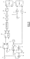
- Figure 2 shows a flow chart for determining the estimated the torque of the at least one electric machine 7.
- the redundant torque controller 16 executes several steps for estimating the torque.
- the redundant torque controller 16 is adapted to estimate the torque of the electric machine based on two received machine currents, a first phase current i1 and a second phase current i2, and the received rotor angular speed ⁇ m of the electric machine 7. According to embodiments, only two of the three phase currents of the electric machine are needed. According to an embodiment, the redundant torque controller 16 realizes the torque estimation using an I- ⁇ estimator, in particular without a look-up table. In other words, the redundant torque controller comprises an I- ⁇ estimator. An I- ⁇ estimator is adapted to calculate the estimated torque T est based on at least two phase currents and the rotor angular speed.
- Phase currents are transformed using a Park transformation in order to get a direct current Id and a quadrature current Iq components.
- the currents Ia and Ib are then transformed in block 22 into a direct current Id and a quadrature current Iq of a rotating coordinate system rotating with the speed of the rotor of the electrical machine:
- R cos ⁇ sin ⁇ ⁇ sin ⁇ cos ⁇ Id
- Iq R ⁇ Ia Ib
- ⁇ is the (electrical) rotational angle of the slip pulsation of the electric machine.
- the rotor angular speed ⁇ m of the electric machine 7 is first multiplied by the number of pair poles np of the electric machine 7 in block 24.
- the rotor pulsation ⁇ r is provided.
- the difference between the stator pulsation ⁇ s and the rotor pulsation ⁇ r is integrated in block 26 to provide the rotational angle ⁇ to the block 22 for calculating the direct current Id and the quadrature current Iq.
- the stator pulsation ⁇ s is calculated by blocks 40, 42, 44: block 40 represents a gain (K2) to adapt the measured input current i1 to the input signal for the phase locked loop (PLL) block 42 which calculates the fundamental stator frequency Fs of the electrical motor.
- the PLL is able to follow the stator frequency for Fs > 3 Hz. This corresponds in an embodiment to about 4 km/h of the speed of the railway vehicle. In other embodiments, depending on the gear ratio between the electric machine and the wheels diameter, the speed may be higher or lower.
- an estimated torque T est is calculated based on the following equation: T est ⁇ K 1 ⁇ np ⁇ L m ⁇ I d ⁇ I q
- Equation (4) represents a simplified I- ⁇ estimator.
- the used value for the electric machine magnetizing inductance Lm is constant (corresponding to the value of the magnetizing inductance at the nominal rotor flux). If a higher precision is needed, the value of the magnetizing inductance Lm could be determined as a function of the magnetizing current Id.
- the absolute value is determined from the intermediate estimated torque Ti, and in block 32, the absolute value is multiplied by the adjustment factor K1.
- an estimated absolute value of the torque is determined as output of block 32.
- the adjustment factor K1 is 1.
- block 32 may be also omitted and the equation (4) further simplified.
- K1 could be chosen in order to fit better the real motor torque.
- a low pass filter 34 is applied to the calculation result of the estimated absolute torque to reduce the ripple, as the phase currents are not exactly sinusoidal, in particular due to an inverter pulse width modulation PWM.
- one or more low pass filters may be arranged between block 22 and block 28.
- the low pass filter has a cutting frequency of about 1 Hz in order to follow the variations of the reference torque. Typically a low pass filter of the first order is adopted.
- the sign of the estimated absolute torque value has to be determined, in particular calculated. That can be simply performed evaluating the sign of the slip pulsation ( ⁇ s - ⁇ r ): in case the electric machine is motoring, the slip is positive, while in case the electric machine is braking, working as a generator, the slip is negative.
- the sign of the slip pulsation is determined (block 46) and compared in block 52 with the sign of the torque command T ref determined in block 48.
- the sign of the torque command T ref is negative.
- the redundant torque controller 16 is adapted to activate the friction brakes (output Alarm 2.
- the absolute value of the estimated torque T est is compared with the absolute value of the torque command T ref .
- the redundant torque controller 16 is adapted to activate the friction brakes (output Alarm 1).
- Figure 3 shows schematically a method according to an embodiment of the present invention.
- a measurement of a first phase current i1 and a second phase current i2 of the asynchronous electric machine 7 is received, for example from the motor controller 12.
- step 102 which may be also before or concurrently to step 100, the rotational speed ⁇ m of the asynchronous electric machine is received, for example from a speed sensor 18.
- step 104 from the measurement of the phase current i1, the PLL 42 determines the stator frequency Fs, from which the stator pulsation ⁇ s is then calculated.
- the difference between the stator pulsation and the rotor pulsation determines the electrical slip pulsation ( ⁇ s - ⁇ r ) which is integrated to evaluate the electrical rotational angle ⁇ which is used for calculating the direct current Id and the quadrature current Iq.
- step 106 an estimated torque T est based on Id and Iq currents and on motor parameters (np and Lm) is calculated.
- step 108 the sign of the slip pulsation ( ⁇ s - ⁇ r ) is compared with the sign of the torque command T ref : in braking operation, when the sign of the torque command is negative, if the sign of the slip pulsation is positive for more than 1 second then, the redundant torque controller 16 is adapted to activate the friction brakes.
- step 110 in braking operation, if the difference between the absolute value of the torque command T ref and the absolute value of the estimated torque T est is greater than a predefined percentage, for example greater than 30 percent, the friction brakes 9 are activated by the redundant torque controller.
- the precision of the estimation is more than 80%, even if for the electric machine magnetizing inductance Lm a constant value is used.
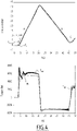
- Figure 4 shows a graph simulating the different currents from standstill of the railway vehicle.
- the railway vehicle first accelerates in a first phase A and then decelerates in a second phase B and finally accelerates again in the phase C.
- the real stator frequency Fs the rotor electrical frequency Fr and the stator frequency Fs est , estimated by the PLL 42, are shown.
Landscapes
- Engineering & Computer Science (AREA)
- Power Engineering (AREA)
- Transportation (AREA)
- Mechanical Engineering (AREA)
- Electric Propulsion And Braking For Vehicles (AREA)
- Control Of Ac Motors In General (AREA)
Description
- The present invention concerns a method for estimating a torque of an asynchronous electric machine of an electric vehicle, in particular a railway vehicle.
- Further, the present invention relates to a controller for an electric vehicle, in particular a railway vehicle.
- Additionally, the present invention relates to an electric vehicle, in particular a railway vehicle.
-
EP 1 322 032 A1 - The article of WINDISCH THOMAS ET AL, IECON 2015 - 41ST ANNUAL CONFERENCE OF THE IEEE INDUSTRIAL ELECTRONICS SOCIETY, IEEE, (20151109), doi:10.1109/IECON.2015.7392318, pages 1530 - 1535: "Loss minimizing and saturation dependent control of induction machines in vehicle applications" relates to the torque estimation of a squirrel cage induction machine.
-
WO 2013/061808 A1 also relates to the estimation of a torque of an induction motor. - Electric vehicles, in particular railway vehicles, require a redundant torque estimation. For example, for safety issues it is required to monitor the electrical braking torque of a railway vehicle in order to activate the mechanical, friction brakes if the electrical braking supplied by the traction machine is lower than defined by the reference command. Usually, safety functions must be independent from a control system.
- The document KUTIJA MARTINA et AL "Magnetization of speed sensor-less squirrel-cage induction generator for wind power application using a phase-locked loop", ELECTRIC POWER SYSTEMS RESEARCH, vol. 122, 1 May 2015 (2015-05-01), pages 119, 129, discloses a PLL-based rotor flux position controller and improves the accuracy of the rotor flux angle.
- Typically, the redundant torque estimation is performed by measuring motor currents and speed and calculating the torque by a look-up table, in which the torque values are stored in correspondence of current and speed pairs. Whenever there is a mismatch of more than 30% between the calculated torque and the commanded torque, the controller issues a torque check failure and activates the friction brakes. In some embodiments, the look-up table is only used for speeds greater than 16 km per hour.
- However, there is not a bijective correspondence between current, speed values and torque. For example, different torque values are possibly depending on the motor flux and on motor parameter values, which are changing with temperature and saturation, so that a look-up table approach may give a wrong torque estimation.
- Object of the invention is to provide a method which overcomes the drawbacks of the look-up table and enables an efficient and accurate estimation of the torque.
- In light of the above, a method for estimating a torque of an asynchronous electric machine of an electric vehicle according to
claim 1 is provided. - The dependent claims set out particular embodiments of the invention.
- According to a further aspect, a method for controlling an electric vehicle, in particular a railway vehicle, is provided comprising: receiving a torque command; estimating the torque according to the method according to an embodiment disclosed herein for determining an estimated torque; comparing the sign of the estimated torque with the sign of the torque command and activating friction brakes if, in braking, the signs are different for more than 1 second, and/or activating friction brakes of the electrical vehicle if the difference between the absolute value of the torque command and the absolute value of estimated torque is greater than a predefined percentage, for example greater than 30 percent.
- According to a further aspect, a torque controller for an electric vehicle, in particular a railway vehicle, is provided according to claim 6.
- Further embodiments may include one or more of the following features in every technically feasible combination:
- the controller is further adapted to transform the first phase current and the second phase current to a direct current and a quadrature current of a rotating coordinate system rotating with the electrical slip pulsation of the electrical machine based on the first phase current and the second phase current and the rotor speed;
- the controller is further adapted to: determine the sign of the torque of the asynchronous electric machine based on the sign of the electrical slip pulsation of the asynchronous electric machine; calculate the estimated torque of the asynchronous electric machine further based on the determined sign of the torque; and/or
- wherein Lm is a constant value correspondent to the value of the inductance at the nominal flux of the asynchronous electric machine.
- According to another aspect, an electric vehicle is provided comprising: at least one asynchronous electric machine, and a torque controller according to an embodiment disclosed herein. So that the manner in which the above recited features of the present invention can be understood in detail, a more particular description of the invention, briefly summarized above, may be read by reference to embodiments. The accompanying drawings relate to embodiments of the invention and are described in the following:
-
Fig. 1 shows schematically a railway vehicle according to an embodiment of the invention; -
Fig. 2 shows schematically a flow chart for estimating a torque of the electrical machine; -
Fig. 3 shows schematically a flow chart of a method according to an embodiment of the invention, and -
Fig. 4 shows a graph with curves of the stator frequency and the estimated torque. -
Figure 1 shows schematically arailway vehicle 1 according to an embodiment of the invention. For example, therailway vehicle 1 may be a tramway, a high speed train a locomotive etc. According to embodiments, the invention may be realized also with other electric vehicles. - The
railway vehicle 1 drives along atrack 3 using a plurality ofwheels 5. Therailway vehicle 1 includes at least one electric machine 7 for driving thewheels 5. The at least one electric machine 7 may be used for accelerating therailway vehicle 1 and for decelerating therailway vehicle 1. The electric machine 7 is used as a traction machine or motor when accelerating therailway vehicle 1 and as a generator when decelerating therailway vehicle 1. According to an embodiment, the electric machine is an asynchronous machine, in particular a three phase asynchronous machine. The at least one electric machine 7 includes a rotor rotating with a rotor angular speed ωm and has a number of pole pairs np. - Further, the
railway vehicle 1 includes a plurality offriction brakes 9 acting on thewheels 5 or on an axle connected to the wheels. Thefriction brakes 9 are adapted to decelerate thewheels 5 when they are activated. For example, they are then generating heat due to friction. - The
railway vehicle 1 includes a motor controller andinverter 12 for each electric machine 7, which generates the phase currents for the respective electric machine 7. Further, themotor controller 12 may include a measurement device for measuring at least two phase currents of different phases. Themotor controller 12 is adapted to receive a torque command Tref from amain controller 14 and to adapt the phase currents of the at least one electric machine 7, such that it corresponds to the requested torque command. - In an embodiment, the
motor controller 12 and/or themain controller 14 includes a primary torque estimator based on phase currents and phase voltages of the at least one electric machine. - Further, the
main controller 14, which is adapted to generate the torque command Tref to be provided to themotor controller 12 and aredundant torque controller 16. Theredundant torque controller 16 is adapted to receive at least the measurement values of two phase currents and the rotor angular speed ωm of the electric machine 7 from amotor speed sensor 18. According to an embodiment, theredundant torque controller 16 is provided on a different hardware with respect to themain controller 14 and/or themotor controller 12. Theredundant torque controller 16 is provided to provide a second estimation of the torque and to compare the second estimated torque with the requested torque Tref. In braking operation, in case the difference between the estimated torque and the requested torque is higher than a predetermined level, the redundant torque controller is adapted to activate thefriction brakes 9. - According to an embodiment, the
railway vehicle 1 includes a speed sensor for measuring the speed of the railway vehicle on thetrack 2. The speed sensor may directly measure the speed or via the rotational speed of thewheels 5. The speed is provided to themain controller 14 and/or theredundant torque controller 16. -
Figure 2 shows a flow chart for determining the estimated the torque of the at least one electric machine 7. In an embodiment, theredundant torque controller 16 executes several steps for estimating the torque. - According to the invention, the
redundant torque controller 16 is adapted to estimate the torque of the electric machine based on two received machine currents, a first phase current i1 and a second phase current i2, and the received rotor angular speed ωm of the electric machine 7. According to embodiments, only two of the three phase currents of the electric machine are needed. According to an embodiment, theredundant torque controller 16 realizes the torque estimation using an I-Ω estimator, in particular without a look-up table. In other words, the redundant torque controller comprises an I-Ω estimator. An I-Ω estimator is adapted to calculate the estimated torque Test based on at least two phase currents and the rotor angular speed. - Phase currents are transformed using a Park transformation in order to get a direct current Id and a quadrature current Iq components. In
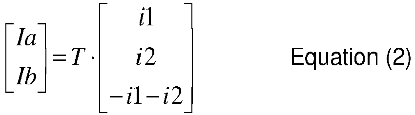
Figure 2 , afirst block 20 is shown, which transforms first phase current i1 and the second phase current i2 into two currents in a complex plane, namely a real portion current Ia and an imaginary part of the current Ib in a fixed coordinate system:
- The currents Ia and Ib are then transformed in
block 22 into a direct current Id and a quadrature current Iq of a rotating coordinate system rotating with the speed of the rotor of the electrical machine:

- The electrical rotational angle is determined using the following equation: θ = np∫(ωs - ωr ). In other words θ is the (electrical) rotational angle of the slip pulsation of the electric machine. According to embodiments, as it can be seen from
Figure 2 , the rotor angular speed ωm of the electric machine 7 is first multiplied by the number of pair poles np of the electric machine 7 inblock 24. As a result the rotor pulsation ωr is provided. The difference between the stator pulsation ωs and the rotor pulsation ωr is integrated inblock 26 to provide the rotational angle θ to theblock 22 for calculating the direct current Id and the quadrature current Iq. - The stator pulsation ωs is calculated by
blocks block 40 represents a gain (K2) to adapt the measured input current i1 to the input signal for the phase locked loop (PLL)block 42 which calculates the fundamental stator frequency Fs of the electrical motor. In an embodiment the PLL is able to follow the stator frequency for Fs > 3 Hz. This corresponds in an embodiment to about 4 km/h of the speed of the railway vehicle. In other embodiments, depending on the gear ratio between the electric machine and the wheels diameter, the speed may be higher or lower. - The stator frequency Fs determined by the PLL in
block 42 is converted in block 44 (K3=2π) to the pulsation ωs - As a next step, an estimated torque Test is calculated based on the following equation:

- In
equation 4, np represents the number of pole pairs, K1 is a factor to adjust the approximated formula, Lm is the nominal value of the electric machine magnetizing inductance, Id is the direct current and Iq is the quadrature current. Equation (4) represents a simplified I-Ω estimator. - In block 28 a first intermediate estimated torque is calculated using the formula Ti=np * Lm * Id * Iq, corresponding to the equation (4) without the adjustment constant K1. According to an embodiment, the used value for the electric machine magnetizing inductance Lm is constant (corresponding to the value of the magnetizing inductance at the nominal rotor flux). If a higher precision is needed, the value of the magnetizing inductance Lm could be determined as a function of the magnetizing current Id.
- In
block 30, the absolute value is determined from the intermediate estimated torque Ti, and inblock 32, the absolute value is multiplied by the adjustment factor K1. Thus, an estimated absolute value of the torque is determined as output ofblock 32. In a typical embodiment, the adjustment factor K1 is 1. In such a case, block 32 may be also omitted and the equation (4) further simplified. In other embodiments, K1 could be chosen in order to fit better the real motor torque. - According to an embodiment, a
low pass filter 34 is applied to the calculation result of the estimated absolute torque to reduce the ripple, as the phase currents are not exactly sinusoidal, in particular due to an inverter pulse width modulation PWM. In other embodiments, one or more low pass filters may be arranged betweenblock 22 andblock 28. In some embodiments, which may be combined with other embodiments disclosed herein, the low pass filter has a cutting frequency of about 1 Hz in order to follow the variations of the reference torque. Typically a low pass filter of the first order is adopted. - According to an embodiment, also the sign of the estimated absolute torque value has to be determined, in particular calculated. That can be simply performed evaluating the sign of the slip pulsation ( ωs - ωr ): in case the electric machine is motoring, the slip is positive, while in case the electric machine is braking, working as a generator, the slip is negative.
- The sign of the slip pulsation is determined (block 46) and compared in
block 52 with the sign of the torque command Tref determined inblock 48. - When the electric machine should be in braking operation, the sign of the torque command Tref is negative. In this case, if the sign of the slip pulsation is positive for more than 1 second then the
redundant torque controller 16 is adapted to activate the friction brakes (output Alarm 2. - Similarly in
block 50 the absolute value of the estimated torque Test is compared with the absolute value of the torque command Tref. - When the electric machine should be in braking operation, the sign of the torque command Tref is negative. In this case (i.e. when the electric machine is in braking operation), if the difference between the absolute value of the torque command Tref and the absolute value of the estimated torque Test is greater than a predefined percentage value, the
redundant torque controller 16 is adapted to activate the friction brakes (output Alarm 1). -
Figure 3 shows schematically a method according to an embodiment of the present invention. - In a
first step 100, a measurement of a first phase current i1 and a second phase current i2 of the asynchronous electric machine 7 is received, for example from themotor controller 12. - In a
second step 102, which may be also before or concurrently to step 100, the rotational speed ωm of the asynchronous electric machine is received, for example from aspeed sensor 18. - In
step 104, from the measurement of the phase current i1, thePLL 42 determines the stator frequency Fs, from which the stator pulsation ωs is then calculated. The difference between the stator pulsation and the rotor pulsation determines the electrical slip pulsation (ωs -ωr ) which is integrated to evaluate the electrical rotational angle θ which is used for calculating the direct current Id and the quadrature current Iq. - In
step 106, an estimated torque Test based on Id and Iq currents and on motor parameters (np and Lm) is calculated. - In
step 108, the sign of the slip pulsation ( ωs - ωr ) is compared with the sign of the torque command Tref : in braking operation, when the sign of the torque command is negative, if the sign of the slip pulsation is positive for more than 1 second then, theredundant torque controller 16 is adapted to activate the friction brakes. - In
step 110, in braking operation, if the difference between the absolute value of the torque command Tref and the absolute value of the estimated torque Test is greater than a predefined percentage, for example greater than 30 percent, thefriction brakes 9 are activated by the redundant torque controller. - In other words, according to the invention, it is possible to use a simplified I-Ω Observer to calculate in real time the electric machine torque, which is also reliable at high speed. In some embodiments, the precision of the estimation is more than 80%, even if for the electric machine magnetizing inductance Lm a constant value is used.
-
Figure 4 shows a graph simulating the different currents from standstill of the railway vehicle. The railway vehicle first accelerates in a first phase A and then decelerates in a second phase B and finally accelerates again in the phase C. In the upper graph the real stator frequency Fs, the rotor electrical frequency Fr and the stator frequency Fsest, estimated by thePLL 42, are shown. - In the lower graph the torque reference Tref , the torque Tobs evaluated by the
motor control 12 and the torque Test estimated by the redundant torque estimator are shown. - As it can be seen, for frequency Fs > 3Hz, the estimated torque Test does not substantially deviate from the torque Tobs evaluated by the
motor control 12.
Claims (10)
- Method for estimating a torque of an asynchronous electric machine (7) of an electric vehicle, in particular a railway vehicle (1), comprising:receiving at least a measurement of a first phase current (i1) and a second phase current (i2) of the asynchronous electric machine (7);receiving a rotor rotational speed (ωm) of the asynchronous electric machine (7); calculating an estimated torque based on the rotor rotational speed of the electric machine and the first and second phase current, the estimated torque is calculated based on the following equation: Test = K1 * np * Lm * Id * Iq, wherein np is the number of pole pairs of the asynchronous electric machine, Lm is the nominal value of an inductance of the asynchronous electric machine (7), and Id is a direct current and Iq is a quadrature current based on the first phase current (i1) and the second phase current (i2), and K1 is an optional adjustment factor, characterized by further comprising: estimating a stator frequency (Fs) of the stator of the electric machine (7) using a phase locked loop based on the first and/or the second phase current (i1, i2), wherein the first phase current (i1) and the second phase current (i2) is transformed to a direct current (Id) and a quadrature current (Iq) of a rotating coordinate system rotating with the electrical slip pulsation of the machine based on the first phase current, the second phase current and the rotor speed (ωm), wherein the electrical rotational angle is determined using the equation θ = np∫(ωs - ωr ), with θ being the electrical rotational angle of the slip pulsation, ωr the rotor pulsation and ωs the stator pulsation, wherein the rotor angular speed (ωm) of the electric machine (7) is multiplied by the number of pole pairs (np) to provide the rotor pulsation (ωr), wherein the stator frequency (Fs) determined by the phased lock loop is converted to the stator pulsation (ωs).
- Method according to one of the preceding claims, wherein Lm is a constant value corresponding to the value of the inductance at the nominal flux of the asynchronous electric machine (7).
- Method according to one of the preceding claims, wherein Lm is variable, according to the saturation curve of the asynchronous electric machine (7).
- Method according to one of the preceding claims, wherein the method further comprises:determining the sign of the torque of the asynchronous electric machine (7) based on the sign of the electrical slip pulsation ( ωs - ωr );calculating the absolute value of the estimated torque of the asynchronous electric machine.
- Method for controlling an electric vehicle, in particular a railway vehicle (1), comprising:receiving a torque command;estimating the torque according to the method according to one of the preceding claims for determining an estimated torque;comparing (108) the sign of the estimated torque (Test) with the sign of the torque command (Tref) and activating friction brakes if, in braking, the signs are different for more than 1 second, and/oractivating friction brakes (110) of the electrical vehicle (1) if the difference between the absolute value of the torque command and the absolute value of estimated torque is greater than a predefined percentage, for example greater than 30 percent.
- Torque controller (16) for an electric vehicle (1), in particular a railway vehicle, the electric vehicle comprises at least one asynchronous electric machine (7), wherein the controller is adapted to receive at least a measurement of a first phase current (i1) and a second phase current (i2) of the at least one asynchronous electric machine (7) and to receive a rotor rotational speed of the at least one asynchronous electric machine, the controller (16) further comprising an I-Ω Estimator (28, 30, 32) for calculating an estimated torque based on the electrical slip pulsation (ωs - ωr ) of the asynchronous electric machine (7) and the first and second phase currents (i1, i2), the controller is further adapted to calculate the estimated torque based on the following equation: Test = K1 * np * Lm * Id * Iq, wherein np is the number of pole pairs of the asynchronous electric machine, Lm is the nominal value of an inductance of the asynchronous electric machine (7), and Id is a direct current and Iq is a quadrature current based on the first phase current (i1) and the second phase current (i2), and K1 is an optional adjustment factor, characterized in that the controller comprises a phase locked loop for estimating a stator frequency (Fs) based on the first and/or the second phase current (i1, i2), wherein the first phase current (i1) and the second phase current (i2) is transformed to a direct current (Id) and a quadrature current (Iq) of a rotating coordinate system rotating with the electrical slip pulsation of the machine based on the first phase current, the second phase current and the rotor speed (ωm), wherein the electrical rotational angle is determined using the equation θ = np∫(ω s - ωr ), with θ being the electrical rotational angle of the slip pulsation, ωr the rotor pulsation and ωs the stator pulsation, wherein the rotor angular speed (ωm) of the electric machine (7) is multiplied by the number of pole pairs (np) to provide the rotor pulsation (ωr), wherein the stator frequency (Fs) determined by the phased lock loop is converted to the stator pulsation (ωs).
- Torque controller (16) according to claim 6, wherein the controller is further adapted to transform the first phase current (i1) and the second phase current (i2) to a direct current (Id) and a quadrature current (Iq) of a rotating coordinate system rotating with the electrical slip pulsation (ωs - ωr ) of the electrical machine based on the first phase current and the second phase current and the rotor speed.
- Torque controller according to any one of the claims 6 or 7, wherein the controller is further adapted to:determine the sign of the torque of the asynchronous electric machine based on the sign of the electrical slip pulsation ( ωs - ωr ) of the asynchronous electric machine (7);calculate the estimated torque of the asynchronous electric machine further based on the determined sign of the torque.
- Torque controller according to any one of the claims 6 to 8, wherein Lm is a constant value correspondent to the value of the inductance at the nominal flux of the asynchronous electric machine.
- Electric vehicle, in particular railway vehicle comprising:at least one asynchronous electric machine, anda torque controller according to one of the claims 6 to 9.
Priority Applications (2)
| Application Number | Priority Date | Filing Date | Title |
|---|---|---|---|
| EP16305180.8A EP3208138B1 (en) | 2016-02-17 | 2016-02-17 | Method for estimating a torque of an asynchronous electric machine, a torque controller and an electric vehicle |
| ES16305180T ES2935480T3 (en) | 2016-02-17 | 2016-02-17 | Method for estimating a motor torque of an asynchronous electric machine, a motor torque controller and an electric vehicle |
Applications Claiming Priority (1)
| Application Number | Priority Date | Filing Date | Title |
|---|---|---|---|
| EP16305180.8A EP3208138B1 (en) | 2016-02-17 | 2016-02-17 | Method for estimating a torque of an asynchronous electric machine, a torque controller and an electric vehicle |
Publications (2)
| Publication Number | Publication Date |
|---|---|
| EP3208138A1 EP3208138A1 (en) | 2017-08-23 |
| EP3208138B1 true EP3208138B1 (en) | 2022-10-12 |
Family
ID=55361447
Family Applications (1)
| Application Number | Title | Priority Date | Filing Date |
|---|---|---|---|
| EP16305180.8A Active EP3208138B1 (en) | 2016-02-17 | 2016-02-17 | Method for estimating a torque of an asynchronous electric machine, a torque controller and an electric vehicle |
Country Status (2)
| Country | Link |
|---|---|
| EP (1) | EP3208138B1 (en) |
| ES (1) | ES2935480T3 (en) |
Families Citing this family (3)
| Publication number | Priority date | Publication date | Assignee | Title |
|---|---|---|---|---|
| CN109849692B (en) * | 2019-03-29 | 2020-09-11 | 深圳猛犸电动科技有限公司 | Method and device for switching control modes of electric vehicle and terminal equipment |
| EP3828648B1 (en) * | 2019-11-28 | 2023-02-15 | ABB Schweiz AG | Motor speed estimation for drive safety system |
| DE102021202926A1 (en) * | 2021-03-25 | 2022-09-29 | Siemens Mobility GmbH | Method for monitoring the operating mode of a variable-speed electric prime mover |
Family Cites Families (6)
| Publication number | Priority date | Publication date | Assignee | Title |
|---|---|---|---|---|
| JPH1023721A (en) * | 1996-07-02 | 1998-01-23 | Toyota Motor Corp | Power output device |
| EP1322032A1 (en) * | 2001-11-13 | 2003-06-25 | Ballard Power Systems Corporation | System and method for electric motor control |
| JP4912516B2 (en) * | 2009-12-08 | 2012-04-11 | 三菱電機株式会社 | Power converter |
| JP5731355B2 (en) * | 2011-10-27 | 2015-06-10 | 日立オートモティブシステムズ株式会社 | Control device for induction motor for vehicle drive |
| US10336212B2 (en) * | 2013-11-27 | 2019-07-02 | Ford Global Technologies, Llc | Torque monitoring system and method |
| JP5888567B2 (en) * | 2014-02-12 | 2016-03-22 | 株式会社デンソー | AC motor control device |
-
2016
- 2016-02-17 ES ES16305180T patent/ES2935480T3/en active Active
- 2016-02-17 EP EP16305180.8A patent/EP3208138B1/en active Active
Non-Patent Citations (1)
| Title |
|---|
| KUTIJA MARTINA ET AL: "Magnetization of speed sensorless squirrel-cage induction generator for wind power application using a phase-locked loop", ELECTRIC POWER SYSTEMS RESEARCH, vol. 122, 1 May 2015 (2015-05-01), AMSTERDAM, NL, pages 119 - 129, XP055817748, ISSN: 0378-7796, DOI: 10.1016/j.epsr.2015.01.009 * |
Also Published As
| Publication number | Publication date |
|---|---|
| ES2935480T3 (en) | 2023-03-07 |
| EP3208138A1 (en) | 2017-08-23 |
Similar Documents
| Publication | Publication Date | Title |
|---|---|---|
| US9054630B2 (en) | Synchronous machine controller | |
| EP2582036B1 (en) | Parameter estimating apparatus for permanent magnet synchronous motor driving system | |
| US7508149B2 (en) | Oil pump systems and methods for preventing torque overload in motors of oil pump systems | |
| EP1193854B1 (en) | Motor control apparatus and control method | |
| CN103378774B (en) | The control device of electric rotating machine | |
| EP1796260A1 (en) | Vector controller of induction motor | |
| EP3223421A1 (en) | Method and apparatus for estimating an angle offset of an angle sensor | |
| US9654031B2 (en) | Power system, power converter controlling apparatus, and electric vehicle having the power system | |
| EP3985862A1 (en) | Device and method for driving permanent magnet synchronous motor, and railway vehicle | |
| US20150149005A1 (en) | Torque monitoring system and method | |
| EP3208138A1 (en) | Method for estimating a torque of an asynchronous electric machine, a torque controller and an electric vehicle | |
| JP5055836B2 (en) | Phase shift detection device and detection method for magnetic pole position sensor for synchronous motor | |
| US8022659B2 (en) | Control apparatus for AC rotary machine and control method for AC rotary machine | |
| EP2822175A1 (en) | Motor control device and control method therefor | |
| Kondo | PMSM and IM rotational sensorless technologies specialized for railway vehicles traction | |
| CN101379690A (en) | Method and device for determining the torque of an electric machine | |
| KR101904374B1 (en) | Motor driving apparatus and electric vehicle including the same | |
| EP3396846A1 (en) | Method for controlling medium-voltage inverter and system comprising the same | |
| EP4016836B1 (en) | A method for categorizing performance of an electric traction machine being a permanent magnetic synchronous motor | |
| Pankhurst | Control of induction motors | |
| EP3144175B1 (en) | Method for controlling an electric vehicle, in particular a railway vehicle, control device for an electric vehicle, and railway vehicle | |
| US10615729B2 (en) | Method for controlling a synchronous machine and control device for a synchronous machine | |
| EP2860870B1 (en) | A method for starting a sensorless permanent magnet motor | |
| Harini et al. | Effect of Initial Rotor Position on Rotor Flux Oriented Speed Permanent Magnet Synchronous Motor Control using Incremental Encoder | |
| ES2926671T3 (en) | Apparatus for correcting current references |
Legal Events
| Date | Code | Title | Description |
|---|---|---|---|
| PUAI | Public reference made under article 153(3) epc to a published international application that has entered the european phase |
Free format text: ORIGINAL CODE: 0009012 |
|
| STAA | Information on the status of an ep patent application or granted ep patent |
Free format text: STATUS: THE APPLICATION HAS BEEN PUBLISHED |
|
| STAA | Information on the status of an ep patent application or granted ep patent |
Free format text: STATUS: REQUEST FOR EXAMINATION WAS MADE |
|
| AK | Designated contracting states |
Kind code of ref document: A1 Designated state(s): AL AT BE BG CH CY CZ DE DK EE ES FI FR GB GR HR HU IE IS IT LI LT LU LV MC MK MT NL NO PL PT RO RS SE SI SK SM TR |
|
| AX | Request for extension of the european patent |
Extension state: BA ME |
|
| 17P | Request for examination filed |
Effective date: 20170804 |
|
| RBV | Designated contracting states (corrected) |
Designated state(s): AL AT BE BG CH CY CZ DE DK EE ES FI FR GB GR HR HU IE IS IT LI LT LU LV MC MK MT NL NO PL PT RO RS SE SI SK SM TR |
|
| STAA | Information on the status of an ep patent application or granted ep patent |
Free format text: STATUS: EXAMINATION IS IN PROGRESS |
|
| 17Q | First examination report despatched |
Effective date: 20200428 |
|
| GRAP | Despatch of communication of intention to grant a patent |
Free format text: ORIGINAL CODE: EPIDOSNIGR1 |
|
| STAA | Information on the status of an ep patent application or granted ep patent |
Free format text: STATUS: GRANT OF PATENT IS INTENDED |
|
| INTG | Intention to grant announced |
Effective date: 20220601 |
|
| GRAS | Grant fee paid |
Free format text: ORIGINAL CODE: EPIDOSNIGR3 |
|
| GRAA | (expected) grant |
Free format text: ORIGINAL CODE: 0009210 |
|
| STAA | Information on the status of an ep patent application or granted ep patent |
Free format text: STATUS: THE PATENT HAS BEEN GRANTED |
|
| AK | Designated contracting states |
Kind code of ref document: B1 Designated state(s): AL AT BE BG CH CY CZ DE DK EE ES FI FR GB GR HR HU IE IS IT LI LT LU LV MC MK MT NL NO PL PT RO RS SE SI SK SM TR |
|
| REG | Reference to a national code |
Ref country code: GB Ref legal event code: FG4D |
|
| REG | Reference to a national code |
Ref country code: CH Ref legal event code: EP |
|
| REG | Reference to a national code |
Ref country code: DE Ref legal event code: R096 Ref document number: 602016075573 Country of ref document: DE |
|
| REG | Reference to a national code |
Ref country code: IE Ref legal event code: FG4D |
|
| REG | Reference to a national code |
Ref country code: AT Ref legal event code: REF Ref document number: 1523966 Country of ref document: AT Kind code of ref document: T Effective date: 20221115 |
|
| REG | Reference to a national code |
Ref country code: LT Ref legal event code: MG9D |
|
| REG | Reference to a national code |
Ref country code: NL Ref legal event code: MP Effective date: 20221012 |
|
| REG | Reference to a national code |
Ref country code: ES Ref legal event code: FG2A Ref document number: 2935480 Country of ref document: ES Kind code of ref document: T3 Effective date: 20230307 |
|
| REG | Reference to a national code |
Ref country code: AT Ref legal event code: MK05 Ref document number: 1523966 Country of ref document: AT Kind code of ref document: T Effective date: 20221012 |
|
| PG25 | Lapsed in a contracting state [announced via postgrant information from national office to epo] |
Ref country code: NL Free format text: LAPSE BECAUSE OF FAILURE TO SUBMIT A TRANSLATION OF THE DESCRIPTION OR TO PAY THE FEE WITHIN THE PRESCRIBED TIME-LIMIT Effective date: 20221012 |
|
| PG25 | Lapsed in a contracting state [announced via postgrant information from national office to epo] |
Ref country code: SE Free format text: LAPSE BECAUSE OF FAILURE TO SUBMIT A TRANSLATION OF THE DESCRIPTION OR TO PAY THE FEE WITHIN THE PRESCRIBED TIME-LIMIT Effective date: 20221012 Ref country code: PT Free format text: LAPSE BECAUSE OF FAILURE TO SUBMIT A TRANSLATION OF THE DESCRIPTION OR TO PAY THE FEE WITHIN THE PRESCRIBED TIME-LIMIT Effective date: 20230213 Ref country code: NO Free format text: LAPSE BECAUSE OF FAILURE TO SUBMIT A TRANSLATION OF THE DESCRIPTION OR TO PAY THE FEE WITHIN THE PRESCRIBED TIME-LIMIT Effective date: 20230112 Ref country code: LT Free format text: LAPSE BECAUSE OF FAILURE TO SUBMIT A TRANSLATION OF THE DESCRIPTION OR TO PAY THE FEE WITHIN THE PRESCRIBED TIME-LIMIT Effective date: 20221012 Ref country code: FI Free format text: LAPSE BECAUSE OF FAILURE TO SUBMIT A TRANSLATION OF THE DESCRIPTION OR TO PAY THE FEE WITHIN THE PRESCRIBED TIME-LIMIT Effective date: 20221012 Ref country code: AT Free format text: LAPSE BECAUSE OF FAILURE TO SUBMIT A TRANSLATION OF THE DESCRIPTION OR TO PAY THE FEE WITHIN THE PRESCRIBED TIME-LIMIT Effective date: 20221012 |
|
| PG25 | Lapsed in a contracting state [announced via postgrant information from national office to epo] |
Ref country code: RS Free format text: LAPSE BECAUSE OF FAILURE TO SUBMIT A TRANSLATION OF THE DESCRIPTION OR TO PAY THE FEE WITHIN THE PRESCRIBED TIME-LIMIT Effective date: 20221012 Ref country code: PL Free format text: LAPSE BECAUSE OF FAILURE TO SUBMIT A TRANSLATION OF THE DESCRIPTION OR TO PAY THE FEE WITHIN THE PRESCRIBED TIME-LIMIT Effective date: 20221012 Ref country code: LV Free format text: LAPSE BECAUSE OF FAILURE TO SUBMIT A TRANSLATION OF THE DESCRIPTION OR TO PAY THE FEE WITHIN THE PRESCRIBED TIME-LIMIT Effective date: 20221012 Ref country code: IS Free format text: LAPSE BECAUSE OF FAILURE TO SUBMIT A TRANSLATION OF THE DESCRIPTION OR TO PAY THE FEE WITHIN THE PRESCRIBED TIME-LIMIT Effective date: 20230212 Ref country code: HR Free format text: LAPSE BECAUSE OF FAILURE TO SUBMIT A TRANSLATION OF THE DESCRIPTION OR TO PAY THE FEE WITHIN THE PRESCRIBED TIME-LIMIT Effective date: 20221012 Ref country code: GR Free format text: LAPSE BECAUSE OF FAILURE TO SUBMIT A TRANSLATION OF THE DESCRIPTION OR TO PAY THE FEE WITHIN THE PRESCRIBED TIME-LIMIT Effective date: 20230113 |
|
| REG | Reference to a national code |
Ref country code: DE Ref legal event code: R097 Ref document number: 602016075573 Country of ref document: DE |
|
| PG25 | Lapsed in a contracting state [announced via postgrant information from national office to epo] |
Ref country code: SM Free format text: LAPSE BECAUSE OF FAILURE TO SUBMIT A TRANSLATION OF THE DESCRIPTION OR TO PAY THE FEE WITHIN THE PRESCRIBED TIME-LIMIT Effective date: 20221012 Ref country code: RO Free format text: LAPSE BECAUSE OF FAILURE TO SUBMIT A TRANSLATION OF THE DESCRIPTION OR TO PAY THE FEE WITHIN THE PRESCRIBED TIME-LIMIT Effective date: 20221012 Ref country code: EE Free format text: LAPSE BECAUSE OF FAILURE TO SUBMIT A TRANSLATION OF THE DESCRIPTION OR TO PAY THE FEE WITHIN THE PRESCRIBED TIME-LIMIT Effective date: 20221012 Ref country code: DK Free format text: LAPSE BECAUSE OF FAILURE TO SUBMIT A TRANSLATION OF THE DESCRIPTION OR TO PAY THE FEE WITHIN THE PRESCRIBED TIME-LIMIT Effective date: 20221012 Ref country code: CZ Free format text: LAPSE BECAUSE OF FAILURE TO SUBMIT A TRANSLATION OF THE DESCRIPTION OR TO PAY THE FEE WITHIN THE PRESCRIBED TIME-LIMIT Effective date: 20221012 |
|
| PLBE | No opposition filed within time limit |
Free format text: ORIGINAL CODE: 0009261 |
|
| STAA | Information on the status of an ep patent application or granted ep patent |
Free format text: STATUS: NO OPPOSITION FILED WITHIN TIME LIMIT |
|
| PG25 | Lapsed in a contracting state [announced via postgrant information from national office to epo] |
Ref country code: SK Free format text: LAPSE BECAUSE OF FAILURE TO SUBMIT A TRANSLATION OF THE DESCRIPTION OR TO PAY THE FEE WITHIN THE PRESCRIBED TIME-LIMIT Effective date: 20221012 Ref country code: AL Free format text: LAPSE BECAUSE OF FAILURE TO SUBMIT A TRANSLATION OF THE DESCRIPTION OR TO PAY THE FEE WITHIN THE PRESCRIBED TIME-LIMIT Effective date: 20221012 |
|
| REG | Reference to a national code |
Ref country code: DE Ref legal event code: R119 Ref document number: 602016075573 Country of ref document: DE |
|
| 26N | No opposition filed |
Effective date: 20230713 |
|
| P01 | Opt-out of the competence of the unified patent court (upc) registered |
Effective date: 20230823 |
|
| PG25 | Lapsed in a contracting state [announced via postgrant information from national office to epo] |
Ref country code: MC Free format text: LAPSE BECAUSE OF FAILURE TO SUBMIT A TRANSLATION OF THE DESCRIPTION OR TO PAY THE FEE WITHIN THE PRESCRIBED TIME-LIMIT Effective date: 20221012 |
|
| REG | Reference to a national code |
Ref country code: CH Ref legal event code: PL |
|
| REG | Reference to a national code |
Ref country code: BE Ref legal event code: MM Effective date: 20230228 |
|
| GBPC | Gb: european patent ceased through non-payment of renewal fee |
Effective date: 20230217 |
|
| PG25 | Lapsed in a contracting state [announced via postgrant information from national office to epo] |
Ref country code: LU Free format text: LAPSE BECAUSE OF NON-PAYMENT OF DUE FEES Effective date: 20230217 Ref country code: LI Free format text: LAPSE BECAUSE OF NON-PAYMENT OF DUE FEES Effective date: 20230228 Ref country code: CH Free format text: LAPSE BECAUSE OF NON-PAYMENT OF DUE FEES Effective date: 20230228 |
|
| PG25 | Lapsed in a contracting state [announced via postgrant information from national office to epo] |
Ref country code: SI Free format text: LAPSE BECAUSE OF FAILURE TO SUBMIT A TRANSLATION OF THE DESCRIPTION OR TO PAY THE FEE WITHIN THE PRESCRIBED TIME-LIMIT Effective date: 20221012 |
|
| REG | Reference to a national code |
Ref country code: IE Ref legal event code: MM4A |
|
| PG25 | Lapsed in a contracting state [announced via postgrant information from national office to epo] |
Ref country code: GB Free format text: LAPSE BECAUSE OF NON-PAYMENT OF DUE FEES Effective date: 20230217 |
|
| PG25 | Lapsed in a contracting state [announced via postgrant information from national office to epo] |
Ref country code: IE Free format text: LAPSE BECAUSE OF NON-PAYMENT OF DUE FEES Effective date: 20230217 Ref country code: GB Free format text: LAPSE BECAUSE OF NON-PAYMENT OF DUE FEES Effective date: 20230217 Ref country code: DE Free format text: LAPSE BECAUSE OF NON-PAYMENT OF DUE FEES Effective date: 20230901 |
|
| PG25 | Lapsed in a contracting state [announced via postgrant information from national office to epo] |
Ref country code: BE Free format text: LAPSE BECAUSE OF NON-PAYMENT OF DUE FEES Effective date: 20230228 |
|
| PG25 | Lapsed in a contracting state [announced via postgrant information from national office to epo] |
Ref country code: IT Free format text: LAPSE BECAUSE OF FAILURE TO SUBMIT A TRANSLATION OF THE DESCRIPTION OR TO PAY THE FEE WITHIN THE PRESCRIBED TIME-LIMIT Effective date: 20221012 |
|
| PG25 | Lapsed in a contracting state [announced via postgrant information from national office to epo] |
Ref country code: BG Free format text: LAPSE BECAUSE OF FAILURE TO SUBMIT A TRANSLATION OF THE DESCRIPTION OR TO PAY THE FEE WITHIN THE PRESCRIBED TIME-LIMIT Effective date: 20221012 |
|
| PG25 | Lapsed in a contracting state [announced via postgrant information from national office to epo] |
Ref country code: BG Free format text: LAPSE BECAUSE OF FAILURE TO SUBMIT A TRANSLATION OF THE DESCRIPTION OR TO PAY THE FEE WITHIN THE PRESCRIBED TIME-LIMIT Effective date: 20221012 |
|
| REG | Reference to a national code |
Ref country code: ES Ref legal event code: PC2A Owner name: ALSTOM HOLDINGS Effective date: 20250310 |
|
| PGFP | Annual fee paid to national office [announced via postgrant information from national office to epo] |
Ref country code: ES Payment date: 20250331 Year of fee payment: 10 |
|
| PG25 | Lapsed in a contracting state [announced via postgrant information from national office to epo] |
Ref country code: CY Free format text: LAPSE BECAUSE OF FAILURE TO SUBMIT A TRANSLATION OF THE DESCRIPTION OR TO PAY THE FEE WITHIN THE PRESCRIBED TIME-LIMIT; INVALID AB INITIO Effective date: 20160217 |
|
| PG25 | Lapsed in a contracting state [announced via postgrant information from national office to epo] |
Ref country code: HU Free format text: LAPSE BECAUSE OF FAILURE TO SUBMIT A TRANSLATION OF THE DESCRIPTION OR TO PAY THE FEE WITHIN THE PRESCRIBED TIME-LIMIT; INVALID AB INITIO Effective date: 20160217 |
|
| PG25 | Lapsed in a contracting state [announced via postgrant information from national office to epo] |
Ref country code: TR Free format text: LAPSE BECAUSE OF FAILURE TO SUBMIT A TRANSLATION OF THE DESCRIPTION OR TO PAY THE FEE WITHIN THE PRESCRIBED TIME-LIMIT Effective date: 20221012 |
|
| PGFP | Annual fee paid to national office [announced via postgrant information from national office to epo] |
Ref country code: FR Payment date: 20260218 Year of fee payment: 11 |