EP3208089A1 - Embedded color bar and method - Google Patents
Embedded color bar and method Download PDFInfo
- Publication number
- EP3208089A1 EP3208089A1 EP17156744.9A EP17156744A EP3208089A1 EP 3208089 A1 EP3208089 A1 EP 3208089A1 EP 17156744 A EP17156744 A EP 17156744A EP 3208089 A1 EP3208089 A1 EP 3208089A1
- Authority
- EP
- European Patent Office
- Prior art keywords
- color
- printed
- color bar
- substrate
- bars
- Prior art date
- Legal status (The legal status is an assumption and is not a legal conclusion. Google has not performed a legal analysis and makes no representation as to the accuracy of the status listed.)
- Granted
Links
Images

Classifications
-
- B—PERFORMING OPERATIONS; TRANSPORTING
- B41—PRINTING; LINING MACHINES; TYPEWRITERS; STAMPS
- B41F—PRINTING MACHINES OR PRESSES
- B41F33/00—Indicating, counting, warning, control or safety devices
- B41F33/0036—Devices for scanning or checking the printed matter for quality control
- B41F33/0045—Devices for scanning or checking the printed matter for quality control for automatically regulating the ink supply
-
- B—PERFORMING OPERATIONS; TRANSPORTING
- B41—PRINTING; LINING MACHINES; TYPEWRITERS; STAMPS
- B41F—PRINTING MACHINES OR PRESSES
- B41F33/00—Indicating, counting, warning, control or safety devices
- B41F33/0036—Devices for scanning or checking the printed matter for quality control
-
- B—PERFORMING OPERATIONS; TRANSPORTING
- B41—PRINTING; LINING MACHINES; TYPEWRITERS; STAMPS
- B41F—PRINTING MACHINES OR PRESSES
- B41F33/00—Indicating, counting, warning, control or safety devices
- B41F33/0081—Devices for scanning register marks
-
- G—PHYSICS
- G01—MEASURING; TESTING
- G01J—MEASUREMENT OF INTENSITY, VELOCITY, SPECTRAL CONTENT, POLARISATION, PHASE OR PULSE CHARACTERISTICS OF INFRARED, VISIBLE OR ULTRAVIOLET LIGHT; COLORIMETRY; RADIATION PYROMETRY
- G01J3/00—Spectrometry; Spectrophotometry; Monochromators; Measuring colours
- G01J3/46—Measurement of colour; Colour measuring devices, e.g. colorimeters
- G01J3/50—Measurement of colour; Colour measuring devices, e.g. colorimeters using electric radiation detectors
- G01J3/51—Measurement of colour; Colour measuring devices, e.g. colorimeters using electric radiation detectors using colour filters
-
- G—PHYSICS
- G01—MEASURING; TESTING
- G01J—MEASUREMENT OF INTENSITY, VELOCITY, SPECTRAL CONTENT, POLARISATION, PHASE OR PULSE CHARACTERISTICS OF INFRARED, VISIBLE OR ULTRAVIOLET LIGHT; COLORIMETRY; RADIATION PYROMETRY
- G01J3/00—Spectrometry; Spectrophotometry; Monochromators; Measuring colours
- G01J3/46—Measurement of colour; Colour measuring devices, e.g. colorimeters
- G01J3/52—Measurement of colour; Colour measuring devices, e.g. colorimeters using colour charts
-
- B—PERFORMING OPERATIONS; TRANSPORTING
- B41—PRINTING; LINING MACHINES; TYPEWRITERS; STAMPS
- B41P—INDEXING SCHEME RELATING TO PRINTING, LINING MACHINES, TYPEWRITERS, AND TO STAMPS
- B41P2233/00—Arrangements for the operation of printing presses
- B41P2233/50—Marks on printed material
- B41P2233/51—Marks on printed material for colour quality control
-
- B—PERFORMING OPERATIONS; TRANSPORTING
- B41—PRINTING; LINING MACHINES; TYPEWRITERS; STAMPS
- B41P—INDEXING SCHEME RELATING TO PRINTING, LINING MACHINES, TYPEWRITERS, AND TO STAMPS
- B41P2233/00—Arrangements for the operation of printing presses
- B41P2233/50—Marks on printed material
- B41P2233/52—Marks on printed material for registering
Definitions
- the present invention relates generally to printing presses and more particularly to color bars for controlling color, registration and ink on a printed substrate.
- U.S. Patent No. 8,763,528 discloses a color control system for use in a printing press.
- the system includes a controller for reviewing digital data for a print job and identifying solid color regions of the print job that are greater than a predetermined size, a user interface allowing an operator to select solid color regions identified by the controller, a sensor for measuring a characteristic of the selected solid color regions of the print job, on a printed substrate, the controller determining measured values of the characteristic for each of the selected solid color regions, and at least one inking unit for supplying ink in a plurality of ink zones to a plate cylinder, the controller varying the ink supplied to ink zones including the solid color regions as function of a difference between the measured value of the characteristic of each selected solid color region and a predetermined target value of the characteristic.
- Color bars are used to control ink on printed substrate.
- the color bar is printed on the substrate and thus requires a clear space on the substrate.
- the space required on the substrate is wasted and the color bar can impact the look of the printed substrate and/or final product if the color bar is embedded in the finished product.
- the color bars may be cut away or discarded from the final product, which may require an additional production step.
- the embedded color bar uses the smallest color bar available for both color and register control. Between each section of color bar, an image of the product may be printed. This differs from the known art, in which the area between the color bars remains unprinted. By filling in the space between each color bar, the bar seems smaller to the end user and the image is far easier to work into the finished product design.
- the present invention provides a printed substrate including a plurality of color bars printed on a substrate, a space between each of the plurality of color bars, and an image printed in the space between at least two of the color bars.
- the present invention also provides an embedded color bar including at least one color bar printed on a substrate and an image printed adjacent the at least one color bar on the substrate.
- the present invention further provides a method of printing an embedded color bar including the steps of printing at least one color bar on a substrate and printing an image adjacent the at least one color bar.
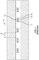
- Fig. 1 shows a plurality of standard color bars 10 printed on a substrate 14 with an unprinted space 12 between each color bar 10.
- Each color bar may include multiple targets 11 and each target may represent a color, for example, cyan, magenta, black or yellow.
- a plurality of color bars 110 are printed on a substrate 114.
- Each color may include a plurality of targets 112, for example, three, four or seven.
- Each target may be a solid density block of a different color, for example, cyan, magenta, black and yellow, green, blue, orange.
- a printed image 116 is also printed on the substrate, the printed image is the desired image for the substrate.
- the image 116 is printed in space 120 between two color bars 110 or adjacent a single color bar 110.
- color bars 110 are embedded in printed image 116. Consequently, the portion of the substrate 114 with color bars 110 is not cut away and discarded as waste.
- a height of color bar 110 may be, for example, 0.095". This dimension can also be decreased to approximately 0.065.”
- a width of color bar 110 varies with the number of targets 112. For example, a color bar 110 including four targets 112 may have a width of 0.300" whereas a color bar 110 having seven targets 112 may have a width of 0.450".
- a distance between the center points of two color bars 110 adjacent one another may be, for example, 40 mm for bars having seven targets 112.
- Each target may be, for example, 0.025" by 0.035".
- a space between each target may be as small as 0.015", however 0.020" may be preferable in order to accommodate for fan out on wide presses. Since each color is print by a different print unit it may also be beneficial to have approximately 0.020" of space between targets 112 to accommodate for any variation in registration or alignment between print units.
- the total area of targets 112 is important in order to get an accurate reading. There can be variation in the length and width dimensions of targets 112, but it is preferable to keep the minimum dimensions to 0.020" to maintain integrity of the print quality. Smaller dimensions may be more difficult for a closed loop color control system to find the targets 112 if are in the printed image.
- color bar 110 So the limit on reducing the size of color bar 110 is the ability to print a good quality mark. If the mark is too small, a print defect may affect the accuracy of the measurements. Color bars 110 and targets 112 may be increased in size and the field of view closed loop color control system may be scaled accordingly.
- small color bars 110 may be used which also reduces waste. Printing an image 116 in the space 120 between color bars 110 provides for maximum image space and allows for the flexibility to provide automatic color control of the color of image 116 that was not previously possible.
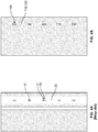
- Figs. 4A and 4B the difference between the embedded color bars 110 in accordance with the present invention and the color bars 10 as known in the art is immediately visible.
- the unprinted stripe 20 of Fig. 4A stands out against the printed substrate.
- the embedded color bars 110 of the present invention are designed to blend into the printed image 116 by printing the area 120 between bars 110 or adjacent a bar 110.
- the embedded color bars 110 may also be designed to be incorporated into printed image 116.
- the visual advantage provided results from a small color bar 110 having small targets 112 with minimal white space therebetween and having color bar 110 surrounded by the image 116.
- the color bars 110 may also be used for register control and alignment.
- a method of printing embedded color bars is also provided.
- the color bars 110 are printed on a substrate with a space 120 between each color bar 110 and a printed image 116 is printed in the space 120 between each color bar or adjacent a single color bar 110.
- Each target 112 in a color bar may be printed by a separate print unit.
Landscapes
- Physics & Mathematics (AREA)
- Spectroscopy & Molecular Physics (AREA)
- Engineering & Computer Science (AREA)
- Quality & Reliability (AREA)
- General Physics & Mathematics (AREA)
- Spectrometry And Color Measurement (AREA)
- Mechanical Pencils And Projecting And Retracting Systems Therefor, And Multi-System Writing Instruments (AREA)
- Printing Methods (AREA)
Abstract
Description
- Priority is hereby claimed to
U.S. Provisional Application No. 62/297,064 - The present invention relates generally to printing presses and more particularly to color bars for controlling color, registration and ink on a printed substrate.
-
U.S. Patent No. 8,763,528 , hereby incorporated by reference herein, discloses a color control system for use in a printing press. The system includes a controller for reviewing digital data for a print job and identifying solid color regions of the print job that are greater than a predetermined size, a user interface allowing an operator to select solid color regions identified by the controller, a sensor for measuring a characteristic of the selected solid color regions of the print job, on a printed substrate, the controller determining measured values of the characteristic for each of the selected solid color regions, and at least one inking unit for supplying ink in a plurality of ink zones to a plate cylinder, the controller varying the ink supplied to ink zones including the solid color regions as function of a difference between the measured value of the characteristic of each selected solid color region and a predetermined target value of the characteristic. - Color bars are used to control ink on printed substrate. The color bar is printed on the substrate and thus requires a clear space on the substrate. The space required on the substrate is wasted and the color bar can impact the look of the printed substrate and/or final product if the color bar is embedded in the finished product. Typically this limits the use of color bars into finished products in packaging, for example, film or board type packaging. The color bars may be cut away or discarded from the final product, which may require an additional production step.
- In order to reduce the negative impact of the color bar on the final products attempts have been made to remove the color bar entirely. Another alternative has been to control color by using the printed image on the substrate. These attempts have been met with little to no success.
- Customer complaints about the web offset printing process in packaging require the printing of color bars in order to control color automatically. Many finished products, for example, labels, pouches and bags, have no location to hide the color bars. Customers find this unacceptable. As a result, the printer of the packaging has to print the packaging without the color bars and thus, without the automatic control of the color. This creates more printed waste. It is not desirable to lack online color control of the printed images.
- The embedded color bar, according to the present invention, uses the smallest color bar available for both color and register control. Between each section of color bar, an image of the product may be printed. This differs from the known art, in which the area between the color bars remains unprinted. By filling in the space between each color bar, the bar seems smaller to the end user and the image is far easier to work into the finished product design.
- The present invention provides a printed substrate including a plurality of color bars printed on a substrate, a space between each of the plurality of color bars, and an image printed in the space between at least two of the color bars.
- The present invention also provides an embedded color bar including at least one color bar printed on a substrate and an image printed adjacent the at least one color bar on the substrate.
- The present invention further provides a method of printing an embedded color bar including the steps of printing at least one color bar on a substrate and printing an image adjacent the at least one color bar.
- A preferred embodiment of the present invention will be elucidated with reference to the drawings, in which:
-
Figs. 1 and4A show color bars printed on a substrate as known in the art; and -
Figs. 2, 3 and4B show a printed substrate having an embedded color bar in accordance with the present invention. -
Fig. 1 shows a plurality ofstandard color bars 10 printed on asubstrate 14 with anunprinted space 12 between eachcolor bar 10. Each color bar may includemultiple targets 11 and each target may represent a color, for example, cyan, magenta, black or yellow. - As shown in
Figs. 2 to 4 , a plurality ofcolor bars 110 are printed on asubstrate 114. Each color may include a plurality oftargets 112, for example, three, four or seven. Each target may be a solid density block of a different color, for example, cyan, magenta, black and yellow, green, blue, orange. A printedimage 116 is also printed on the substrate, the printed image is the desired image for the substrate. Theimage 116 is printed inspace 120 between twocolor bars 110 or adjacent asingle color bar 110. Thus,color bars 110 are embedded in printedimage 116. Consequently, the portion of thesubstrate 114 withcolor bars 110 is not cut away and discarded as waste. - A height of
color bar 110 may be, for example, 0.095". This dimension can also be decreased to approximately 0.065." A width ofcolor bar 110 varies with the number oftargets 112. For example, acolor bar 110 including fourtargets 112 may have a width of 0.300" whereas acolor bar 110 having seventargets 112 may have a width of 0.450". A distance between the center points of twocolor bars 110 adjacent one another may be, for example, 40 mm for bars having seventargets 112. - Each target may be, for example, 0.025" by 0.035". A space between each target may be as small as 0.015", however 0.020" may be preferable in order to accommodate for fan out on wide presses. Since each color is print by a different print unit it may also be beneficial to have approximately 0.020" of space between
targets 112 to accommodate for any variation in registration or alignment between print units. The total area oftargets 112 is important in order to get an accurate reading. There can be variation in the length and width dimensions oftargets 112, but it is preferable to keep the minimum dimensions to 0.020" to maintain integrity of the print quality. Smaller dimensions may be more difficult for a closed loop color control system to find thetargets 112 if are in the printed image. So the limit on reducing the size ofcolor bar 110 is the ability to print a good quality mark. If the mark is too small, a print defect may affect the accuracy of the measurements.Color bars 110 andtargets 112 may be increased in size and the field of view closed loop color control system may be scaled accordingly. - In accordance with the present invention,
small color bars 110 may be used which also reduces waste. Printing animage 116 in thespace 120 betweencolor bars 110 provides for maximum image space and allows for the flexibility to provide automatic color control of the color ofimage 116 that was not previously possible. - As shown in
Figs. 4A and 4B , the difference between the embeddedcolor bars 110 in accordance with the present invention and thecolor bars 10 as known in the art is immediately visible. Theunprinted stripe 20 ofFig. 4A stands out against the printed substrate. - In contrast, the embedded
color bars 110 of the present invention are designed to blend into the printedimage 116 by printing thearea 120 betweenbars 110 or adjacent abar 110. The embeddedcolor bars 110 may also be designed to be incorporated into printedimage 116. The visual advantage provided results from asmall color bar 110 havingsmall targets 112 with minimal white space therebetween and havingcolor bar 110 surrounded by theimage 116. - The
color bars 110 may also be used for register control and alignment. - A method of printing embedded color bars is also provided. The
color bars 110 are printed on a substrate with aspace 120 between eachcolor bar 110 and a printedimage 116 is printed in thespace 120 between each color bar or adjacent asingle color bar 110. Eachtarget 112 in a color bar may be printed by a separate print unit. - In the preceding specification, the invention has been described with reference to specific exemplary embodiments and examples thereof. It will, however, be evident that various modifications and changes may be made thereto without departing from the broader spirit and scope of invention as set forth in the claims that follow. The specification and drawings are accordingly to be regarded in an illustrative manner rather than a restrictive sense.
Claims (14)
- A printed substrate comprising:a plurality of color bars printed on a substrate;a space between each of the plurality of color bars; andan image printed in the space between at least two of the color bars.
- The printed substrate as recited in claim 1, wherein each color bar includes at least one target.
- The printed substrate as recited in claim 2, wherein each color bar includes at least two targets.
- The printed substrate or embedded color bar as recited in claim 3 wherein each target is a different color.
- The printed substrate as recited in any one of claims 1 to 4, wherein the color bar is incorporated into the printed image.
- An embedded color bar comprising:at least one color bar printed on a substrate;an image printed adjacent the at least one color bar on the substrate.
- The embedded color bar as recited in claim 6, wherein the at least one color bar includes two color bars and the image is printed in a space between the at least two color bars on the substrate.
- The embedded color bar as recited in claim 6 or 7, wherein the at least one color bar includes at least one target.
- The printed substrate as recited in claim 8, wherein each color bar includes at least two targets.
- The embedded color bar as recited in claim 9, wherein each target is a different color.
- The embedded color bar as recited in any one of claims 6 to 10, wherein the color bar is incorporated into the printed image.
- A method of printing an embedded color bar comprising the steps of:printing at least one color bar on a substrate; andprinting an image adjacent the at least one color bar.
- The method recited in claim 12, wherein at least two color bars are printed on the substrate and the image is printed in an area between the at least two color bars.
- The method of printing an embedded color bar according to claim 12 or 13 further comprising the step of:printing a second color bar adjacent the image.
Applications Claiming Priority (1)
| Application Number | Priority Date | Filing Date | Title |
|---|---|---|---|
| US201662297064P | 2016-02-18 | 2016-02-18 |
Publications (2)
| Publication Number | Publication Date |
|---|---|
| EP3208089A1 true EP3208089A1 (en) | 2017-08-23 |
| EP3208089B1 EP3208089B1 (en) | 2023-07-26 |
Family
ID=58094267
Family Applications (1)
| Application Number | Title | Priority Date | Filing Date |
|---|---|---|---|
| EP17156744.9A Active EP3208089B1 (en) | 2016-02-18 | 2017-02-17 | Embedded color bar and pritning method |
Country Status (3)
| Country | Link |
|---|---|
| US (1) | US20170348966A1 (en) |
| EP (1) | EP3208089B1 (en) |
| ES (1) | ES2951893T3 (en) |
Families Citing this family (1)
| Publication number | Priority date | Publication date | Assignee | Title |
|---|---|---|---|---|
| EP2439071A1 (en) * | 2010-10-11 | 2012-04-11 | KBA-NotaSys SA | Color control pattern for the optical measurement of colors printed on a sheet-like or web-like substrate by means of a multicolor printing press and uses thereof |
Citations (7)
| Publication number | Priority date | Publication date | Assignee | Title |
|---|---|---|---|---|
| US20070266878A1 (en) * | 2003-11-21 | 2007-11-22 | Underwood John A | Eye marks in image processing |
| DE102008056170A1 (en) * | 2007-11-30 | 2009-06-04 | Heidelberger Druckmaschinen Ag | Print substrate assigning method for artwork, involves comparing markings with already identified markings in measuring device or computer, and assigning markings to already identified markings, where markings are inserted in data sets |
| DE102009007864A1 (en) * | 2008-03-10 | 2009-09-17 | Heidelberger Druckmaschinen Ag | Print image-dependent positioning of color measurement strips |
| EP2127878A1 (en) * | 2008-05-27 | 2009-12-02 | manroland AG | Method for determining print process parameters using cameras, illuminators and a test pattern |
| EP2368711A1 (en) * | 2010-03-25 | 2011-09-28 | Modesto Luengo Bada | Mark, method and system for color quality parameters measurement |
| WO2012140384A2 (en) * | 2011-04-14 | 2012-10-18 | Serge Hasle Camille | Printing test method on a substrate and device for the implementation thereof |
| US8763528B2 (en) | 2010-12-09 | 2014-07-01 | Goss International Americas, Inc. | Closed loop color control of selected regions using solid color regions within images |
Family Cites Families (1)
| Publication number | Priority date | Publication date | Assignee | Title |
|---|---|---|---|---|
| US5946414A (en) * | 1998-08-28 | 1999-08-31 | Xerox Corporation | Encoding data in color images using patterned color modulated image regions |
-
2017
- 2017-02-17 EP EP17156744.9A patent/EP3208089B1/en active Active
- 2017-02-17 US US15/435,472 patent/US20170348966A1/en not_active Abandoned
- 2017-02-17 ES ES17156744T patent/ES2951893T3/en active Active
Patent Citations (7)
| Publication number | Priority date | Publication date | Assignee | Title |
|---|---|---|---|---|
| US20070266878A1 (en) * | 2003-11-21 | 2007-11-22 | Underwood John A | Eye marks in image processing |
| DE102008056170A1 (en) * | 2007-11-30 | 2009-06-04 | Heidelberger Druckmaschinen Ag | Print substrate assigning method for artwork, involves comparing markings with already identified markings in measuring device or computer, and assigning markings to already identified markings, where markings are inserted in data sets |
| DE102009007864A1 (en) * | 2008-03-10 | 2009-09-17 | Heidelberger Druckmaschinen Ag | Print image-dependent positioning of color measurement strips |
| EP2127878A1 (en) * | 2008-05-27 | 2009-12-02 | manroland AG | Method for determining print process parameters using cameras, illuminators and a test pattern |
| EP2368711A1 (en) * | 2010-03-25 | 2011-09-28 | Modesto Luengo Bada | Mark, method and system for color quality parameters measurement |
| US8763528B2 (en) | 2010-12-09 | 2014-07-01 | Goss International Americas, Inc. | Closed loop color control of selected regions using solid color regions within images |
| WO2012140384A2 (en) * | 2011-04-14 | 2012-10-18 | Serge Hasle Camille | Printing test method on a substrate and device for the implementation thereof |
Also Published As
| Publication number | Publication date |
|---|---|
| US20170348966A1 (en) | 2017-12-07 |
| EP3208089B1 (en) | 2023-07-26 |
| ES2951893T3 (en) | 2023-10-25 |
Similar Documents
| Publication | Publication Date | Title |
|---|---|---|
| US11247450B2 (en) | Method for determining print parameters of a printing machine and test stand | |
| EP2842304B1 (en) | Methods and systems of generating a lenticular article using a printing blanket | |
| EP1464493B2 (en) | A printing press | |
| JP5881576B2 (en) | Image evaluation apparatus, image evaluation method, image evaluation system, and program | |
| IL194063A (en) | System and method for inspecting image quality in a printing press | |
| EP2463102B1 (en) | Closed loop color control of selected regions using solid color regions within images | |
| JP2001088273A (en) | Equipment for measuring printed products with a densitometer | |
| US20190283396A1 (en) | Printing Press, Method and Apparatus for Correcting a Printing Position of a Printing Unit | |
| DE10244437B4 (en) | Method for determining the position and shape of marks on a printed paper web | |
| EP2368711B1 (en) | Mark, method and system for color quality parameters measurement | |
| US20170348966A1 (en) | Embedded Color Bar and Method | |
| CN108353111B (en) | Print inconsistency quantification | |
| CN106371967B (en) | Method for assessing the importance of deactivated printing nozzles in an inkjet printing system | |
| WO2020094791A1 (en) | Digital printing head | |
| CN101837675A (en) | Be used for controlling the method for the inking of printing machine | |
| EP2874007B1 (en) | Digital printing method and system with left/right correction | |
| CN116494645B (en) | Method for adapting Lab nominal color values of multicolor printed products | |
| EP4275904B1 (en) | Print quality control system for offset printing machine | |
| CN112078243A (en) | Simplified sheet stretch measurement | |
| EP4173832A1 (en) | Method for controlling a printing device and printing device | |
| US8561537B2 (en) | Apparatus for the automatic determination of presetting values for inking zone setting elements of an inking unit of a press | |
| WO2008026589A1 (en) | Printer print evaluation information display device and print evaluation information display method | |
| Răzvan-George | Real time quality control of the heatset offset printing process | |
| Nagai et al. | Development of Color Control System by Measurement of Whole Print Image for Offset Printing Press | |
| CN112238683A (en) | Register measurement with white separation color |
Legal Events
| Date | Code | Title | Description |
|---|---|---|---|
| PUAI | Public reference made under article 153(3) epc to a published international application that has entered the european phase |
Free format text: ORIGINAL CODE: 0009012 |
|
| STAA | Information on the status of an ep patent application or granted ep patent |
Free format text: STATUS: THE APPLICATION HAS BEEN PUBLISHED |
|
| AK | Designated contracting states |
Kind code of ref document: A1 Designated state(s): AL AT BE BG CH CY CZ DE DK EE ES FI FR GB GR HR HU IE IS IT LI LT LU LV MC MK MT NL NO PL PT RO RS SE SI SK SM TR |
|
| AX | Request for extension of the european patent |
Extension state: BA ME |
|
| STAA | Information on the status of an ep patent application or granted ep patent |
Free format text: STATUS: REQUEST FOR EXAMINATION WAS MADE |
|
| STAA | Information on the status of an ep patent application or granted ep patent |
Free format text: STATUS: EXAMINATION IS IN PROGRESS |
|
| 17P | Request for examination filed |
Effective date: 20180112 |
|
| RBV | Designated contracting states (corrected) |
Designated state(s): AL AT BE BG CH CY CZ DE DK EE ES FI FR GB GR HR HU IE IS IT LI LT LU LV MC MK MT NL NO PL PT RO RS SE SI SK SM TR |
|
| 17Q | First examination report despatched |
Effective date: 20180219 |
|
| RAP1 | Party data changed (applicant data changed or rights of an application transferred) |
Owner name: MANROLAND GOSS WEB SYSTEMS GMBH |
|
| GRAP | Despatch of communication of intention to grant a patent |
Free format text: ORIGINAL CODE: EPIDOSNIGR1 |
|
| STAA | Information on the status of an ep patent application or granted ep patent |
Free format text: STATUS: GRANT OF PATENT IS INTENDED |
|
| RIC1 | Information provided on ipc code assigned before grant |
Ipc: G01J 3/52 20060101ALI20230314BHEP Ipc: B42D 25/405 20140101ALI20230314BHEP Ipc: B42D 25/48 20140101ALI20230314BHEP Ipc: B41F 33/00 20060101AFI20230314BHEP |
|
| INTG | Intention to grant announced |
Effective date: 20230417 |
|
| GRAS | Grant fee paid |
Free format text: ORIGINAL CODE: EPIDOSNIGR3 |
|
| GRAA | (expected) grant |
Free format text: ORIGINAL CODE: 0009210 |
|
| STAA | Information on the status of an ep patent application or granted ep patent |
Free format text: STATUS: THE PATENT HAS BEEN GRANTED |
|
| AK | Designated contracting states |
Kind code of ref document: B1 Designated state(s): AL AT BE BG CH CY CZ DE DK EE ES FI FR GB GR HR HU IE IS IT LI LT LU LV MC MK MT NL NO PL PT RO RS SE SI SK SM TR |
|
| REG | Reference to a national code |
Ref country code: GB Ref legal event code: FG4D |
|
| REG | Reference to a national code |
Ref country code: CH Ref legal event code: EP |
|
| REG | Reference to a national code |
Ref country code: DE Ref legal event code: R096 Ref document number: 602017071700 Country of ref document: DE |
|
| REG | Reference to a national code |
Ref country code: IE Ref legal event code: FG4D |
|
| REG | Reference to a national code |
Ref country code: SE Ref legal event code: TRGR |
|
| REG | Reference to a national code |
Ref country code: ES Ref legal event code: FG2A Ref document number: 2951893 Country of ref document: ES Kind code of ref document: T3 Effective date: 20231025 |
|
| REG | Reference to a national code |
Ref country code: NL Ref legal event code: FP |
|
| REG | Reference to a national code |
Ref country code: LT Ref legal event code: MG9D |
|
| REG | Reference to a national code |
Ref country code: AT Ref legal event code: MK05 Ref document number: 1591538 Country of ref document: AT Kind code of ref document: T Effective date: 20230726 |
|
| PG25 | Lapsed in a contracting state [announced via postgrant information from national office to epo] |
Ref country code: GR Free format text: LAPSE BECAUSE OF FAILURE TO SUBMIT A TRANSLATION OF THE DESCRIPTION OR TO PAY THE FEE WITHIN THE PRESCRIBED TIME-LIMIT Effective date: 20231027 |
|
| PG25 | Lapsed in a contracting state [announced via postgrant information from national office to epo] |
Ref country code: IS Free format text: LAPSE BECAUSE OF FAILURE TO SUBMIT A TRANSLATION OF THE DESCRIPTION OR TO PAY THE FEE WITHIN THE PRESCRIBED TIME-LIMIT Effective date: 20231126 |
|
| PG25 | Lapsed in a contracting state [announced via postgrant information from national office to epo] |
Ref country code: RS Free format text: LAPSE BECAUSE OF FAILURE TO SUBMIT A TRANSLATION OF THE DESCRIPTION OR TO PAY THE FEE WITHIN THE PRESCRIBED TIME-LIMIT Effective date: 20230726 Ref country code: PT Free format text: LAPSE BECAUSE OF FAILURE TO SUBMIT A TRANSLATION OF THE DESCRIPTION OR TO PAY THE FEE WITHIN THE PRESCRIBED TIME-LIMIT Effective date: 20231127 Ref country code: NO Free format text: LAPSE BECAUSE OF FAILURE TO SUBMIT A TRANSLATION OF THE DESCRIPTION OR TO PAY THE FEE WITHIN THE PRESCRIBED TIME-LIMIT Effective date: 20231026 Ref country code: LV Free format text: LAPSE BECAUSE OF FAILURE TO SUBMIT A TRANSLATION OF THE DESCRIPTION OR TO PAY THE FEE WITHIN THE PRESCRIBED TIME-LIMIT Effective date: 20230726 Ref country code: LT Free format text: LAPSE BECAUSE OF FAILURE TO SUBMIT A TRANSLATION OF THE DESCRIPTION OR TO PAY THE FEE WITHIN THE PRESCRIBED TIME-LIMIT Effective date: 20230726 Ref country code: IS Free format text: LAPSE BECAUSE OF FAILURE TO SUBMIT A TRANSLATION OF THE DESCRIPTION OR TO PAY THE FEE WITHIN THE PRESCRIBED TIME-LIMIT Effective date: 20231126 Ref country code: HR Free format text: LAPSE BECAUSE OF FAILURE TO SUBMIT A TRANSLATION OF THE DESCRIPTION OR TO PAY THE FEE WITHIN THE PRESCRIBED TIME-LIMIT Effective date: 20230726 Ref country code: GR Free format text: LAPSE BECAUSE OF FAILURE TO SUBMIT A TRANSLATION OF THE DESCRIPTION OR TO PAY THE FEE WITHIN THE PRESCRIBED TIME-LIMIT Effective date: 20231027 Ref country code: FI Free format text: LAPSE BECAUSE OF FAILURE TO SUBMIT A TRANSLATION OF THE DESCRIPTION OR TO PAY THE FEE WITHIN THE PRESCRIBED TIME-LIMIT Effective date: 20230726 Ref country code: AT Free format text: LAPSE BECAUSE OF FAILURE TO SUBMIT A TRANSLATION OF THE DESCRIPTION OR TO PAY THE FEE WITHIN THE PRESCRIBED TIME-LIMIT Effective date: 20230726 |
|
| PG25 | Lapsed in a contracting state [announced via postgrant information from national office to epo] |
Ref country code: PL Free format text: LAPSE BECAUSE OF FAILURE TO SUBMIT A TRANSLATION OF THE DESCRIPTION OR TO PAY THE FEE WITHIN THE PRESCRIBED TIME-LIMIT Effective date: 20230726 |
|
| REG | Reference to a national code |
Ref country code: DE Ref legal event code: R097 Ref document number: 602017071700 Country of ref document: DE |
|
| PG25 | Lapsed in a contracting state [announced via postgrant information from national office to epo] |
Ref country code: SM Free format text: LAPSE BECAUSE OF FAILURE TO SUBMIT A TRANSLATION OF THE DESCRIPTION OR TO PAY THE FEE WITHIN THE PRESCRIBED TIME-LIMIT Effective date: 20230726 Ref country code: RO Free format text: LAPSE BECAUSE OF FAILURE TO SUBMIT A TRANSLATION OF THE DESCRIPTION OR TO PAY THE FEE WITHIN THE PRESCRIBED TIME-LIMIT Effective date: 20230726 Ref country code: EE Free format text: LAPSE BECAUSE OF FAILURE TO SUBMIT A TRANSLATION OF THE DESCRIPTION OR TO PAY THE FEE WITHIN THE PRESCRIBED TIME-LIMIT Effective date: 20230726 Ref country code: DK Free format text: LAPSE BECAUSE OF FAILURE TO SUBMIT A TRANSLATION OF THE DESCRIPTION OR TO PAY THE FEE WITHIN THE PRESCRIBED TIME-LIMIT Effective date: 20230726 Ref country code: CZ Free format text: LAPSE BECAUSE OF FAILURE TO SUBMIT A TRANSLATION OF THE DESCRIPTION OR TO PAY THE FEE WITHIN THE PRESCRIBED TIME-LIMIT Effective date: 20230726 Ref country code: SK Free format text: LAPSE BECAUSE OF FAILURE TO SUBMIT A TRANSLATION OF THE DESCRIPTION OR TO PAY THE FEE WITHIN THE PRESCRIBED TIME-LIMIT Effective date: 20230726 |
|
| PLBE | No opposition filed within time limit |
Free format text: ORIGINAL CODE: 0009261 |
|
| STAA | Information on the status of an ep patent application or granted ep patent |
Free format text: STATUS: NO OPPOSITION FILED WITHIN TIME LIMIT |
|
| 26N | No opposition filed |
Effective date: 20240429 |
|
| PG25 | Lapsed in a contracting state [announced via postgrant information from national office to epo] |
Ref country code: SI Free format text: LAPSE BECAUSE OF FAILURE TO SUBMIT A TRANSLATION OF THE DESCRIPTION OR TO PAY THE FEE WITHIN THE PRESCRIBED TIME-LIMIT Effective date: 20230726 |
|
| PG25 | Lapsed in a contracting state [announced via postgrant information from national office to epo] |
Ref country code: MC Free format text: LAPSE BECAUSE OF FAILURE TO SUBMIT A TRANSLATION OF THE DESCRIPTION OR TO PAY THE FEE WITHIN THE PRESCRIBED TIME-LIMIT Effective date: 20230726 |
|
| REG | Reference to a national code |
Ref country code: CH Ref legal event code: PL |
|
| PG25 | Lapsed in a contracting state [announced via postgrant information from national office to epo] |
Ref country code: LU Free format text: LAPSE BECAUSE OF NON-PAYMENT OF DUE FEES Effective date: 20240217 |
|
| PG25 | Lapsed in a contracting state [announced via postgrant information from national office to epo] |
Ref country code: CH Free format text: LAPSE BECAUSE OF NON-PAYMENT OF DUE FEES Effective date: 20240229 |
|
| PG25 | Lapsed in a contracting state [announced via postgrant information from national office to epo] |
Ref country code: LU Free format text: LAPSE BECAUSE OF NON-PAYMENT OF DUE FEES Effective date: 20240217 Ref country code: CH Free format text: LAPSE BECAUSE OF NON-PAYMENT OF DUE FEES Effective date: 20240229 |
|
| PG25 | Lapsed in a contracting state [announced via postgrant information from national office to epo] |
Ref country code: BG Free format text: LAPSE BECAUSE OF FAILURE TO SUBMIT A TRANSLATION OF THE DESCRIPTION OR TO PAY THE FEE WITHIN THE PRESCRIBED TIME-LIMIT Effective date: 20230726 |
|
| PG25 | Lapsed in a contracting state [announced via postgrant information from national office to epo] |
Ref country code: BG Free format text: LAPSE BECAUSE OF FAILURE TO SUBMIT A TRANSLATION OF THE DESCRIPTION OR TO PAY THE FEE WITHIN THE PRESCRIBED TIME-LIMIT Effective date: 20230726 |
|
| REG | Reference to a national code |
Ref country code: BE Ref legal event code: MM Effective date: 20240229 |
|
| PG25 | Lapsed in a contracting state [announced via postgrant information from national office to epo] |
Ref country code: BE Free format text: LAPSE BECAUSE OF NON-PAYMENT OF DUE FEES Effective date: 20240229 |
|
| PG25 | Lapsed in a contracting state [announced via postgrant information from national office to epo] |
Ref country code: IE Free format text: LAPSE BECAUSE OF NON-PAYMENT OF DUE FEES Effective date: 20240217 |
|
| PG25 | Lapsed in a contracting state [announced via postgrant information from national office to epo] |
Ref country code: IE Free format text: LAPSE BECAUSE OF NON-PAYMENT OF DUE FEES Effective date: 20240217 Ref country code: BE Free format text: LAPSE BECAUSE OF NON-PAYMENT OF DUE FEES Effective date: 20240229 |
|
| PG25 | Lapsed in a contracting state [announced via postgrant information from national office to epo] |
Ref country code: CY Free format text: LAPSE BECAUSE OF FAILURE TO SUBMIT A TRANSLATION OF THE DESCRIPTION OR TO PAY THE FEE WITHIN THE PRESCRIBED TIME-LIMIT; INVALID AB INITIO Effective date: 20170217 |
|
| PG25 | Lapsed in a contracting state [announced via postgrant information from national office to epo] |
Ref country code: HU Free format text: LAPSE BECAUSE OF FAILURE TO SUBMIT A TRANSLATION OF THE DESCRIPTION OR TO PAY THE FEE WITHIN THE PRESCRIBED TIME-LIMIT; INVALID AB INITIO Effective date: 20170217 |
|
| PG25 | Lapsed in a contracting state [announced via postgrant information from national office to epo] |
Ref country code: TR Free format text: LAPSE BECAUSE OF FAILURE TO SUBMIT A TRANSLATION OF THE DESCRIPTION OR TO PAY THE FEE WITHIN THE PRESCRIBED TIME-LIMIT Effective date: 20230726 |
|
| PGFP | Annual fee paid to national office [announced via postgrant information from national office to epo] |
Ref country code: NL Payment date: 20260218 Year of fee payment: 10 |
|
| PGFP | Annual fee paid to national office [announced via postgrant information from national office to epo] |
Ref country code: SE Payment date: 20260218 Year of fee payment: 10 |
|
| PGFP | Annual fee paid to national office [announced via postgrant information from national office to epo] |
Ref country code: GB Payment date: 20260219 Year of fee payment: 10 |
|
| PGFP | Annual fee paid to national office [announced via postgrant information from national office to epo] |
Ref country code: DE Payment date: 20260218 Year of fee payment: 10 |
|
| PGFP | Annual fee paid to national office [announced via postgrant information from national office to epo] |
Ref country code: IT Payment date: 20260224 Year of fee payment: 10 |
|
| PGFP | Annual fee paid to national office [announced via postgrant information from national office to epo] |
Ref country code: FR Payment date: 20260218 Year of fee payment: 10 |
|
| PGFP | Annual fee paid to national office [announced via postgrant information from national office to epo] |
Ref country code: ES Payment date: 20260408 Year of fee payment: 10 |