EP3208080B1 - A structure formed from composite material - Google Patents
A structure formed from composite material Download PDFInfo
- Publication number
- EP3208080B1 EP3208080B1 EP16201817.0A EP16201817A EP3208080B1 EP 3208080 B1 EP3208080 B1 EP 3208080B1 EP 16201817 A EP16201817 A EP 16201817A EP 3208080 B1 EP3208080 B1 EP 3208080B1
- Authority
- EP
- European Patent Office
- Prior art keywords
- metallic layer
- layer
- composite
- sealant layer
- structural member
- Prior art date
- Legal status (The legal status is an assumption and is not a legal conclusion. Google has not performed a legal analysis and makes no representation as to the accuracy of the status listed.)
- Active
Links
Images


Classifications
-
- B—PERFORMING OPERATIONS; TRANSPORTING
- B29—WORKING OF PLASTICS; WORKING OF SUBSTANCES IN A PLASTIC STATE IN GENERAL
- B29C—SHAPING OR JOINING OF PLASTICS; SHAPING OF MATERIAL IN A PLASTIC STATE, NOT OTHERWISE PROVIDED FOR; AFTER-TREATMENT OF THE SHAPED PRODUCTS, e.g. REPAIRING
- B29C70/00—Shaping composites, i.e. plastics material comprising reinforcements, fillers or preformed parts, e.g. inserts
- B29C70/88—Shaping composites, i.e. plastics material comprising reinforcements, fillers or preformed parts, e.g. inserts characterised primarily by possessing specific properties, e.g. electrically conductive or locally reinforced
- B29C70/882—Shaping composites, i.e. plastics material comprising reinforcements, fillers or preformed parts, e.g. inserts characterised primarily by possessing specific properties, e.g. electrically conductive or locally reinforced partly or totally electrically conductive, e.g. for EMI shielding
- B29C70/885—Shaping composites, i.e. plastics material comprising reinforcements, fillers or preformed parts, e.g. inserts characterised primarily by possessing specific properties, e.g. electrically conductive or locally reinforced partly or totally electrically conductive, e.g. for EMI shielding with incorporated metallic wires, nets, films or plates
-
- B—PERFORMING OPERATIONS; TRANSPORTING
- B32—LAYERED PRODUCTS
- B32B—LAYERED PRODUCTS, i.e. PRODUCTS BUILT-UP OF STRATA OF FLAT OR NON-FLAT, e.g. CELLULAR OR HONEYCOMB, FORM
- B32B15/00—Layered products comprising a layer of metal
- B32B15/04—Layered products comprising a layer of metal comprising metal as the main or only constituent of a layer, which is next to another layer of the same or of a different material
- B32B15/08—Layered products comprising a layer of metal comprising metal as the main or only constituent of a layer, which is next to another layer of the same or of a different material of synthetic resin
-
- B—PERFORMING OPERATIONS; TRANSPORTING
- B32—LAYERED PRODUCTS
- B32B—LAYERED PRODUCTS, i.e. PRODUCTS BUILT-UP OF STRATA OF FLAT OR NON-FLAT, e.g. CELLULAR OR HONEYCOMB, FORM
- B32B15/00—Layered products comprising a layer of metal
- B32B15/04—Layered products comprising a layer of metal comprising metal as the main or only constituent of a layer, which is next to another layer of the same or of a different material
- B32B15/08—Layered products comprising a layer of metal comprising metal as the main or only constituent of a layer, which is next to another layer of the same or of a different material of synthetic resin
- B32B15/095—Layered products comprising a layer of metal comprising metal as the main or only constituent of a layer, which is next to another layer of the same or of a different material of synthetic resin comprising polyurethanes
-
- B—PERFORMING OPERATIONS; TRANSPORTING
- B32—LAYERED PRODUCTS
- B32B—LAYERED PRODUCTS, i.e. PRODUCTS BUILT-UP OF STRATA OF FLAT OR NON-FLAT, e.g. CELLULAR OR HONEYCOMB, FORM
- B32B15/00—Layered products comprising a layer of metal
- B32B15/20—Layered products comprising a layer of metal comprising aluminium or copper
-
- B—PERFORMING OPERATIONS; TRANSPORTING
- B32—LAYERED PRODUCTS
- B32B—LAYERED PRODUCTS, i.e. PRODUCTS BUILT-UP OF STRATA OF FLAT OR NON-FLAT, e.g. CELLULAR OR HONEYCOMB, FORM
- B32B27/00—Layered products comprising a layer of synthetic resin
- B32B27/04—Layered products comprising a layer of synthetic resin as impregnant, bonding, or embedding substance
-
- B—PERFORMING OPERATIONS; TRANSPORTING
- B32—LAYERED PRODUCTS
- B32B—LAYERED PRODUCTS, i.e. PRODUCTS BUILT-UP OF STRATA OF FLAT OR NON-FLAT, e.g. CELLULAR OR HONEYCOMB, FORM
- B32B27/00—Layered products comprising a layer of synthetic resin
- B32B27/06—Layered products comprising a layer of synthetic resin as the main or only constituent of a layer, which is next to another layer of the same or of a different material
-
- B—PERFORMING OPERATIONS; TRANSPORTING
- B32—LAYERED PRODUCTS
- B32B—LAYERED PRODUCTS, i.e. PRODUCTS BUILT-UP OF STRATA OF FLAT OR NON-FLAT, e.g. CELLULAR OR HONEYCOMB, FORM
- B32B27/00—Layered products comprising a layer of synthetic resin
- B32B27/06—Layered products comprising a layer of synthetic resin as the main or only constituent of a layer, which is next to another layer of the same or of a different material
- B32B27/08—Layered products comprising a layer of synthetic resin as the main or only constituent of a layer, which is next to another layer of the same or of a different material of synthetic resin
-
- B—PERFORMING OPERATIONS; TRANSPORTING
- B32—LAYERED PRODUCTS
- B32B—LAYERED PRODUCTS, i.e. PRODUCTS BUILT-UP OF STRATA OF FLAT OR NON-FLAT, e.g. CELLULAR OR HONEYCOMB, FORM
- B32B27/00—Layered products comprising a layer of synthetic resin
- B32B27/40—Layered products comprising a layer of synthetic resin comprising polyurethanes
-
- B—PERFORMING OPERATIONS; TRANSPORTING
- B32—LAYERED PRODUCTS
- B32B—LAYERED PRODUCTS, i.e. PRODUCTS BUILT-UP OF STRATA OF FLAT OR NON-FLAT, e.g. CELLULAR OR HONEYCOMB, FORM
- B32B3/00—Layered products comprising a layer with external or internal discontinuities or unevennesses, or a layer of non-planar shape; Layered products comprising a layer having particular features of form
- B32B3/02—Layered products comprising a layer with external or internal discontinuities or unevennesses, or a layer of non-planar shape; Layered products comprising a layer having particular features of form characterised by features of form at particular places, e.g. in edge regions
-
- B—PERFORMING OPERATIONS; TRANSPORTING
- B32—LAYERED PRODUCTS
- B32B—LAYERED PRODUCTS, i.e. PRODUCTS BUILT-UP OF STRATA OF FLAT OR NON-FLAT, e.g. CELLULAR OR HONEYCOMB, FORM
- B32B3/00—Layered products comprising a layer with external or internal discontinuities or unevennesses, or a layer of non-planar shape; Layered products comprising a layer having particular features of form
- B32B3/02—Layered products comprising a layer with external or internal discontinuities or unevennesses, or a layer of non-planar shape; Layered products comprising a layer having particular features of form characterised by features of form at particular places, e.g. in edge regions
- B32B3/04—Layered products comprising a layer with external or internal discontinuities or unevennesses, or a layer of non-planar shape; Layered products comprising a layer having particular features of form characterised by features of form at particular places, e.g. in edge regions characterised by at least one layer folded at the edge, e.g. over another layer ; characterised by at least one layer enveloping or enclosing a material
-
- B—PERFORMING OPERATIONS; TRANSPORTING
- B32—LAYERED PRODUCTS
- B32B—LAYERED PRODUCTS, i.e. PRODUCTS BUILT-UP OF STRATA OF FLAT OR NON-FLAT, e.g. CELLULAR OR HONEYCOMB, FORM
- B32B3/00—Layered products comprising a layer with external or internal discontinuities or unevennesses, or a layer of non-planar shape; Layered products comprising a layer having particular features of form
- B32B3/10—Layered products comprising a layer with external or internal discontinuities or unevennesses, or a layer of non-planar shape; Layered products comprising a layer having particular features of form characterised by a discontinuous layer, i.e. formed of separate pieces of material
-
- B—PERFORMING OPERATIONS; TRANSPORTING
- B32—LAYERED PRODUCTS
- B32B—LAYERED PRODUCTS, i.e. PRODUCTS BUILT-UP OF STRATA OF FLAT OR NON-FLAT, e.g. CELLULAR OR HONEYCOMB, FORM
- B32B5/00—Layered products characterised by the non- homogeneity or physical structure, i.e. comprising a fibrous, filamentary, particulate or foam layer; Layered products characterised by having a layer differing constitutionally or physically in different parts
- B32B5/02—Layered products characterised by the non- homogeneity or physical structure, i.e. comprising a fibrous, filamentary, particulate or foam layer; Layered products characterised by having a layer differing constitutionally or physically in different parts characterised by structural features of a fibrous or filamentary layer
-
- B—PERFORMING OPERATIONS; TRANSPORTING
- B32—LAYERED PRODUCTS
- B32B—LAYERED PRODUCTS, i.e. PRODUCTS BUILT-UP OF STRATA OF FLAT OR NON-FLAT, e.g. CELLULAR OR HONEYCOMB, FORM
- B32B5/00—Layered products characterised by the non- homogeneity or physical structure, i.e. comprising a fibrous, filamentary, particulate or foam layer; Layered products characterised by having a layer differing constitutionally or physically in different parts
- B32B5/22—Layered products characterised by the non- homogeneity or physical structure, i.e. comprising a fibrous, filamentary, particulate or foam layer; Layered products characterised by having a layer differing constitutionally or physically in different parts characterised by the presence of two or more layers which are next to each other and are fibrous, filamentary, formed of particles or foamed
- B32B5/24—Layered products characterised by the non- homogeneity or physical structure, i.e. comprising a fibrous, filamentary, particulate or foam layer; Layered products characterised by having a layer differing constitutionally or physically in different parts characterised by the presence of two or more layers which are next to each other and are fibrous, filamentary, formed of particles or foamed one layer being a fibrous or filamentary layer
- B32B5/26—Layered products characterised by the non- homogeneity or physical structure, i.e. comprising a fibrous, filamentary, particulate or foam layer; Layered products characterised by having a layer differing constitutionally or physically in different parts characterised by the presence of two or more layers which are next to each other and are fibrous, filamentary, formed of particles or foamed one layer being a fibrous or filamentary layer another layer next to it also being fibrous or filamentary
-
- B—PERFORMING OPERATIONS; TRANSPORTING
- B32—LAYERED PRODUCTS
- B32B—LAYERED PRODUCTS, i.e. PRODUCTS BUILT-UP OF STRATA OF FLAT OR NON-FLAT, e.g. CELLULAR OR HONEYCOMB, FORM
- B32B5/00—Layered products characterised by the non- homogeneity or physical structure, i.e. comprising a fibrous, filamentary, particulate or foam layer; Layered products characterised by having a layer differing constitutionally or physically in different parts
- B32B5/22—Layered products characterised by the non- homogeneity or physical structure, i.e. comprising a fibrous, filamentary, particulate or foam layer; Layered products characterised by having a layer differing constitutionally or physically in different parts characterised by the presence of two or more layers which are next to each other and are fibrous, filamentary, formed of particles or foamed
- B32B5/24—Layered products characterised by the non- homogeneity or physical structure, i.e. comprising a fibrous, filamentary, particulate or foam layer; Layered products characterised by having a layer differing constitutionally or physically in different parts characterised by the presence of two or more layers which are next to each other and are fibrous, filamentary, formed of particles or foamed one layer being a fibrous or filamentary layer
- B32B5/28—Layered products characterised by the non- homogeneity or physical structure, i.e. comprising a fibrous, filamentary, particulate or foam layer; Layered products characterised by having a layer differing constitutionally or physically in different parts characterised by the presence of two or more layers which are next to each other and are fibrous, filamentary, formed of particles or foamed one layer being a fibrous or filamentary layer impregnated with or embedded in a plastic substance
-
- B—PERFORMING OPERATIONS; TRANSPORTING
- B32—LAYERED PRODUCTS
- B32B—LAYERED PRODUCTS, i.e. PRODUCTS BUILT-UP OF STRATA OF FLAT OR NON-FLAT, e.g. CELLULAR OR HONEYCOMB, FORM
- B32B9/00—Layered products comprising a layer of a particular substance not covered by groups B32B11/00 - B32B29/00
- B32B9/005—Layered products comprising a layer of a particular substance not covered by groups B32B11/00 - B32B29/00 comprising one layer of ceramic material, e.g. porcelain, ceramic tile
- B32B9/007—Layered products comprising a layer of a particular substance not covered by groups B32B11/00 - B32B29/00 comprising one layer of ceramic material, e.g. porcelain, ceramic tile comprising carbon, e.g. graphite, composite carbon
-
- B—PERFORMING OPERATIONS; TRANSPORTING
- B64—AIRCRAFT; AVIATION; COSMONAUTICS
- B64C—AEROPLANES; HELICOPTERS
- B64C1/00—Fuselages; Constructional features common to fuselages, wings, stabilising surfaces or the like
- B64C1/06—Frames; Stringers; Longerons ; Fuselage sections
- B64C1/12—Construction or attachment of skin panels
-
- B—PERFORMING OPERATIONS; TRANSPORTING
- B64—AIRCRAFT; AVIATION; COSMONAUTICS
- B64C—AEROPLANES; HELICOPTERS
- B64C3/00—Wings
- B64C3/20—Integral or sandwich constructions
-
- B—PERFORMING OPERATIONS; TRANSPORTING
- B64—AIRCRAFT; AVIATION; COSMONAUTICS
- B64C—AEROPLANES; HELICOPTERS
- B64C3/00—Wings
- B64C3/24—Moulded or cast structures
-
- B—PERFORMING OPERATIONS; TRANSPORTING
- B64—AIRCRAFT; AVIATION; COSMONAUTICS
- B64C—AEROPLANES; HELICOPTERS
- B64C3/00—Wings
- B64C3/26—Construction, shape, or attachment of separate skins, e.g. panels
-
- B—PERFORMING OPERATIONS; TRANSPORTING
- B64—AIRCRAFT; AVIATION; COSMONAUTICS
- B64D—EQUIPMENT FOR FITTING IN OR TO AIRCRAFT; FLIGHT SUITS; PARACHUTES; ARRANGEMENT OR MOUNTING OF POWER PLANTS OR PROPULSION TRANSMISSIONS IN AIRCRAFT
- B64D45/00—Aircraft indicators or protectors not otherwise provided for
- B64D45/02—Lightning protectors; Static dischargers
-
- B—PERFORMING OPERATIONS; TRANSPORTING
- B32—LAYERED PRODUCTS
- B32B—LAYERED PRODUCTS, i.e. PRODUCTS BUILT-UP OF STRATA OF FLAT OR NON-FLAT, e.g. CELLULAR OR HONEYCOMB, FORM
- B32B38/00—Ancillary operations in connection with laminating processes
- B32B38/0012—Mechanical treatment, e.g. roughening, deforming, stretching
- B32B2038/002—Sandblasting
-
- B—PERFORMING OPERATIONS; TRANSPORTING
- B32—LAYERED PRODUCTS
- B32B—LAYERED PRODUCTS, i.e. PRODUCTS BUILT-UP OF STRATA OF FLAT OR NON-FLAT, e.g. CELLULAR OR HONEYCOMB, FORM
- B32B38/00—Ancillary operations in connection with laminating processes
- B32B2038/0052—Other operations not otherwise provided for
- B32B2038/0092—Metallizing
-
- B—PERFORMING OPERATIONS; TRANSPORTING
- B32—LAYERED PRODUCTS
- B32B—LAYERED PRODUCTS, i.e. PRODUCTS BUILT-UP OF STRATA OF FLAT OR NON-FLAT, e.g. CELLULAR OR HONEYCOMB, FORM
- B32B2255/00—Coating on the layer surface
- B32B2255/02—Coating on the layer surface on fibrous or filamentary layer
-
- B—PERFORMING OPERATIONS; TRANSPORTING
- B32—LAYERED PRODUCTS
- B32B—LAYERED PRODUCTS, i.e. PRODUCTS BUILT-UP OF STRATA OF FLAT OR NON-FLAT, e.g. CELLULAR OR HONEYCOMB, FORM
- B32B2255/00—Coating on the layer surface
- B32B2255/10—Coating on the layer surface on synthetic resin layer or on natural or synthetic rubber layer
-
- B—PERFORMING OPERATIONS; TRANSPORTING
- B32—LAYERED PRODUCTS
- B32B—LAYERED PRODUCTS, i.e. PRODUCTS BUILT-UP OF STRATA OF FLAT OR NON-FLAT, e.g. CELLULAR OR HONEYCOMB, FORM
- B32B2255/00—Coating on the layer surface
- B32B2255/20—Inorganic coating
- B32B2255/205—Metallic coating
-
- B—PERFORMING OPERATIONS; TRANSPORTING
- B32—LAYERED PRODUCTS
- B32B—LAYERED PRODUCTS, i.e. PRODUCTS BUILT-UP OF STRATA OF FLAT OR NON-FLAT, e.g. CELLULAR OR HONEYCOMB, FORM
- B32B2255/00—Coating on the layer surface
- B32B2255/26—Polymeric coating
-
- B—PERFORMING OPERATIONS; TRANSPORTING
- B32—LAYERED PRODUCTS
- B32B—LAYERED PRODUCTS, i.e. PRODUCTS BUILT-UP OF STRATA OF FLAT OR NON-FLAT, e.g. CELLULAR OR HONEYCOMB, FORM
- B32B2255/00—Coating on the layer surface
- B32B2255/28—Multiple coating on one surface
-
- B—PERFORMING OPERATIONS; TRANSPORTING
- B32—LAYERED PRODUCTS
- B32B—LAYERED PRODUCTS, i.e. PRODUCTS BUILT-UP OF STRATA OF FLAT OR NON-FLAT, e.g. CELLULAR OR HONEYCOMB, FORM
- B32B2260/00—Layered product comprising an impregnated, embedded, or bonded layer wherein the layer comprises an impregnation, embedding, or binder material
- B32B2260/02—Composition of the impregnated, bonded or embedded layer
- B32B2260/021—Fibrous or filamentary layer
-
- B—PERFORMING OPERATIONS; TRANSPORTING
- B32—LAYERED PRODUCTS
- B32B—LAYERED PRODUCTS, i.e. PRODUCTS BUILT-UP OF STRATA OF FLAT OR NON-FLAT, e.g. CELLULAR OR HONEYCOMB, FORM
- B32B2260/00—Layered product comprising an impregnated, embedded, or bonded layer wherein the layer comprises an impregnation, embedding, or binder material
- B32B2260/02—Composition of the impregnated, bonded or embedded layer
- B32B2260/021—Fibrous or filamentary layer
- B32B2260/023—Two or more layers
-
- B—PERFORMING OPERATIONS; TRANSPORTING
- B32—LAYERED PRODUCTS
- B32B—LAYERED PRODUCTS, i.e. PRODUCTS BUILT-UP OF STRATA OF FLAT OR NON-FLAT, e.g. CELLULAR OR HONEYCOMB, FORM
- B32B2260/00—Layered product comprising an impregnated, embedded, or bonded layer wherein the layer comprises an impregnation, embedding, or binder material
- B32B2260/04—Impregnation, embedding, or binder material
- B32B2260/046—Synthetic resin
-
- B—PERFORMING OPERATIONS; TRANSPORTING
- B32—LAYERED PRODUCTS
- B32B—LAYERED PRODUCTS, i.e. PRODUCTS BUILT-UP OF STRATA OF FLAT OR NON-FLAT, e.g. CELLULAR OR HONEYCOMB, FORM
- B32B2262/00—Composition or structural features of fibres which form a fibrous or filamentary layer or are present as additives
- B32B2262/10—Inorganic fibres
- B32B2262/106—Carbon fibres, e.g. graphite fibres
-
- B—PERFORMING OPERATIONS; TRANSPORTING
- B32—LAYERED PRODUCTS
- B32B—LAYERED PRODUCTS, i.e. PRODUCTS BUILT-UP OF STRATA OF FLAT OR NON-FLAT, e.g. CELLULAR OR HONEYCOMB, FORM
- B32B2305/00—Condition, form or state of the layers or laminate
- B32B2305/07—Parts immersed or impregnated in a matrix
-
- B—PERFORMING OPERATIONS; TRANSPORTING
- B32—LAYERED PRODUCTS
- B32B—LAYERED PRODUCTS, i.e. PRODUCTS BUILT-UP OF STRATA OF FLAT OR NON-FLAT, e.g. CELLULAR OR HONEYCOMB, FORM
- B32B2305/00—Condition, form or state of the layers or laminate
- B32B2305/08—Reinforcements
-
- B—PERFORMING OPERATIONS; TRANSPORTING
- B32—LAYERED PRODUCTS
- B32B—LAYERED PRODUCTS, i.e. PRODUCTS BUILT-UP OF STRATA OF FLAT OR NON-FLAT, e.g. CELLULAR OR HONEYCOMB, FORM
- B32B2307/00—Properties of the layers or laminate
- B32B2307/20—Properties of the layers or laminate having particular electrical or magnetic properties, e.g. piezoelectric
- B32B2307/202—Conductive
-
- B—PERFORMING OPERATIONS; TRANSPORTING
- B32—LAYERED PRODUCTS
- B32B—LAYERED PRODUCTS, i.e. PRODUCTS BUILT-UP OF STRATA OF FLAT OR NON-FLAT, e.g. CELLULAR OR HONEYCOMB, FORM
- B32B2307/00—Properties of the layers or laminate
- B32B2307/20—Properties of the layers or laminate having particular electrical or magnetic properties, e.g. piezoelectric
- B32B2307/206—Insulating
-
- B—PERFORMING OPERATIONS; TRANSPORTING
- B32—LAYERED PRODUCTS
- B32B—LAYERED PRODUCTS, i.e. PRODUCTS BUILT-UP OF STRATA OF FLAT OR NON-FLAT, e.g. CELLULAR OR HONEYCOMB, FORM
- B32B2307/00—Properties of the layers or laminate
- B32B2307/20—Properties of the layers or laminate having particular electrical or magnetic properties, e.g. piezoelectric
- B32B2307/21—Anti-static
-
- B—PERFORMING OPERATIONS; TRANSPORTING
- B32—LAYERED PRODUCTS
- B32B—LAYERED PRODUCTS, i.e. PRODUCTS BUILT-UP OF STRATA OF FLAT OR NON-FLAT, e.g. CELLULAR OR HONEYCOMB, FORM
- B32B2307/00—Properties of the layers or laminate
- B32B2307/50—Properties of the layers or laminate having particular mechanical properties
- B32B2307/558—Impact strength, toughness
-
- B—PERFORMING OPERATIONS; TRANSPORTING
- B32—LAYERED PRODUCTS
- B32B—LAYERED PRODUCTS, i.e. PRODUCTS BUILT-UP OF STRATA OF FLAT OR NON-FLAT, e.g. CELLULAR OR HONEYCOMB, FORM
- B32B2307/00—Properties of the layers or laminate
- B32B2307/70—Other properties
- B32B2307/714—Inert, i.e. inert to chemical degradation, corrosion
-
- B—PERFORMING OPERATIONS; TRANSPORTING
- B32—LAYERED PRODUCTS
- B32B—LAYERED PRODUCTS, i.e. PRODUCTS BUILT-UP OF STRATA OF FLAT OR NON-FLAT, e.g. CELLULAR OR HONEYCOMB, FORM
- B32B2307/00—Properties of the layers or laminate
- B32B2307/70—Other properties
- B32B2307/732—Dimensional properties
-
- B—PERFORMING OPERATIONS; TRANSPORTING
- B32—LAYERED PRODUCTS
- B32B—LAYERED PRODUCTS, i.e. PRODUCTS BUILT-UP OF STRATA OF FLAT OR NON-FLAT, e.g. CELLULAR OR HONEYCOMB, FORM
- B32B2307/00—Properties of the layers or laminate
- B32B2307/70—Other properties
- B32B2307/752—Corrosion inhibitor
-
- B—PERFORMING OPERATIONS; TRANSPORTING
- B32—LAYERED PRODUCTS
- B32B—LAYERED PRODUCTS, i.e. PRODUCTS BUILT-UP OF STRATA OF FLAT OR NON-FLAT, e.g. CELLULAR OR HONEYCOMB, FORM
- B32B2311/00—Metals, their alloys or their compounds
- B32B2311/02—Noble metals
- B32B2311/08—Silver
-
- B—PERFORMING OPERATIONS; TRANSPORTING
- B32—LAYERED PRODUCTS
- B32B—LAYERED PRODUCTS, i.e. PRODUCTS BUILT-UP OF STRATA OF FLAT OR NON-FLAT, e.g. CELLULAR OR HONEYCOMB, FORM
- B32B2311/00—Metals, their alloys or their compounds
- B32B2311/12—Copper
-
- B—PERFORMING OPERATIONS; TRANSPORTING
- B32—LAYERED PRODUCTS
- B32B—LAYERED PRODUCTS, i.e. PRODUCTS BUILT-UP OF STRATA OF FLAT OR NON-FLAT, e.g. CELLULAR OR HONEYCOMB, FORM
- B32B2311/00—Metals, their alloys or their compounds
- B32B2311/20—Zinc
-
- B—PERFORMING OPERATIONS; TRANSPORTING
- B32—LAYERED PRODUCTS
- B32B—LAYERED PRODUCTS, i.e. PRODUCTS BUILT-UP OF STRATA OF FLAT OR NON-FLAT, e.g. CELLULAR OR HONEYCOMB, FORM
- B32B2311/00—Metals, their alloys or their compounds
- B32B2311/22—Nickel or cobalt
-
- B—PERFORMING OPERATIONS; TRANSPORTING
- B32—LAYERED PRODUCTS
- B32B—LAYERED PRODUCTS, i.e. PRODUCTS BUILT-UP OF STRATA OF FLAT OR NON-FLAT, e.g. CELLULAR OR HONEYCOMB, FORM
- B32B2311/00—Metals, their alloys or their compounds
- B32B2311/24—Aluminium
-
- B—PERFORMING OPERATIONS; TRANSPORTING
- B32—LAYERED PRODUCTS
- B32B—LAYERED PRODUCTS, i.e. PRODUCTS BUILT-UP OF STRATA OF FLAT OR NON-FLAT, e.g. CELLULAR OR HONEYCOMB, FORM
- B32B2375/00—Polyureas; Polyurethanes
-
- B—PERFORMING OPERATIONS; TRANSPORTING
- B32—LAYERED PRODUCTS
- B32B—LAYERED PRODUCTS, i.e. PRODUCTS BUILT-UP OF STRATA OF FLAT OR NON-FLAT, e.g. CELLULAR OR HONEYCOMB, FORM
- B32B2419/00—Buildings or parts thereof
-
- B—PERFORMING OPERATIONS; TRANSPORTING
- B32—LAYERED PRODUCTS
- B32B—LAYERED PRODUCTS, i.e. PRODUCTS BUILT-UP OF STRATA OF FLAT OR NON-FLAT, e.g. CELLULAR OR HONEYCOMB, FORM
- B32B2605/00—Vehicles
- B32B2605/08—Cars
-
- B—PERFORMING OPERATIONS; TRANSPORTING
- B32—LAYERED PRODUCTS
- B32B—LAYERED PRODUCTS, i.e. PRODUCTS BUILT-UP OF STRATA OF FLAT OR NON-FLAT, e.g. CELLULAR OR HONEYCOMB, FORM
- B32B2605/00—Vehicles
- B32B2605/12—Ships
-
- B—PERFORMING OPERATIONS; TRANSPORTING
- B32—LAYERED PRODUCTS
- B32B—LAYERED PRODUCTS, i.e. PRODUCTS BUILT-UP OF STRATA OF FLAT OR NON-FLAT, e.g. CELLULAR OR HONEYCOMB, FORM
- B32B2605/00—Vehicles
- B32B2605/18—Aircraft
-
- B—PERFORMING OPERATIONS; TRANSPORTING
- B64—AIRCRAFT; AVIATION; COSMONAUTICS
- B64C—AEROPLANES; HELICOPTERS
- B64C1/00—Fuselages; Constructional features common to fuselages, wings, stabilising surfaces or the like
- B64C2001/0054—Fuselage structures substantially made from particular materials
- B64C2001/0072—Fuselage structures substantially made from particular materials from composite materials
-
- B—PERFORMING OPERATIONS; TRANSPORTING
- B64—AIRCRAFT; AVIATION; COSMONAUTICS
- B64C—AEROPLANES; HELICOPTERS
- B64C1/00—Fuselages; Constructional features common to fuselages, wings, stabilising surfaces or the like
- B64C2001/0054—Fuselage structures substantially made from particular materials
- B64C2001/0081—Fuselage structures substantially made from particular materials from metallic materials
-
- Y—GENERAL TAGGING OF NEW TECHNOLOGICAL DEVELOPMENTS; GENERAL TAGGING OF CROSS-SECTIONAL TECHNOLOGIES SPANNING OVER SEVERAL SECTIONS OF THE IPC; TECHNICAL SUBJECTS COVERED BY FORMER USPC CROSS-REFERENCE ART COLLECTIONS [XRACs] AND DIGESTS
- Y02—TECHNOLOGIES OR APPLICATIONS FOR MITIGATION OR ADAPTATION AGAINST CLIMATE CHANGE
- Y02T—CLIMATE CHANGE MITIGATION TECHNOLOGIES RELATED TO TRANSPORTATION
- Y02T50/00—Aeronautics or air transport
- Y02T50/40—Weight reduction
Definitions
- each of the wing covers 113 comprises a composite structural member 201 made up of carbon fibre layers 203 bound in matrix layers 205 of a thermoset polymer.
- a sealant layer 207 substantially covers the upper surface of the wing cover 113 in figure 2 .
- the sealant layer 207 is approximately 15 ⁇ m to 25 ⁇ m thick.
- the sealant layer 207 is in the form of a polyurethane ultra-violet light (UV) resistant clear-coat varnish.
- the wing cover 113 further comprises a first metallic layer 209 disposed on the exterior surface of the wing cover 113 over the sealant layer 207.
- the extent of the first metallic layer 209 is limited to within the extent of the sealant layer 207.
- the first metallic layer 209 extends to within a predetermined distance 211 of the edge of the sealant layer 207 on which it is disposed. In the present example, the predetermined distance is 10mm.
- the first metallic layer 209 comprises a 15 ⁇ m thick layer of aluminium that is applied by a thermal spray deposition method. Aluminium is highly electrically conductive and arranged to dissipate electrical charge in the surface of the wing cover 113 which may, for example, result from lightning strike or static build-up.
- a paint system 213 is provided on the wing cover 113 over the exposed surfaces of the sealant layer 207 and the first metallic layer 209. The paint system 213 provides environmental protection for the first metallic layer 209 in addition to its aesthetic effects for the wing cover 113.
- the presence of the sealant layer 207 results in a significant reduction of the erosion of the exterior surface of the paint system 213.
- the resilient flexure of the sealant layer 207 improves the ability of the paint system to resist erosion from soft or hard particle impact.
- the sealant layer 207 comprises a polyurethane material with a finished thickness of up to 15 ⁇ m to 35 ⁇ m and is applied by spraying.
- a second keying process is applied to the exterior surface of the sealant layer 207 to provide a second surface key 305 to aid adhesion of subsequent layers.
- the first metallic layer 209 is applied to the upper surface of the sealant layer 207 up to the predetermined distance 211 from the edges of the sealant layer 207.
- the first metallic layer 209 comprises aluminium with a thickness of up to 15 ⁇ m and is applied by thermal spraying.
- the paint system 213 is then applied to the exposed respective upper surfaces of the sealant layer 207 and the first metallic layer 209.
- the paint system 213 comprises a primer coat and one or more top coats (not shown separately).
- the ECF strip 407 is integrally formed in the upper surface of the wing cover 113.
- the fasteners 401 are fixed through a fastener region 411 located generally centrally widthwise along the ECF strip 407.
- the fasteners 401 are formed from a titanium alloy and fixed onto the aluminium spar 403 resulting in an electrically conductive path between the outside and the inside of the wing cover 113.
- the sealant layer 207 extends over the outer surface of the wing cover 113 up to the edge of the holes 409 for the fasteners 401.
- the first metallic layer 209 on the sealant layer 207 extends over the edge of the ECF strip 407 so as to form an overlap 413 of a predetermined width configured to provide electrical continuity between the first metallic layer 209 and the ECF strip 407.
- the overlap 413 has a width of at least 10mm.
- the edge of the first metallic layer 209 is spaced a predetermined distance 415 from the fastener region 411 of the ECF strip 407.
- the predetermined distance 415 is configured so as to reduce the probability of galvanic corrosion in response to electrical continuity between the first metallic layer 209 and the fastener 401 enabled by a failure in the paint system 213 adjacent the head 401.
- the predetermined distance is 10mm.
- the method of manufacturing the composite structure of figure 4 according to the invention will now be described by way of the additional steps to the method described above with reference to figures 3a to 3f .
- the second metallic layer 407 in the form of the ECF strip is integrally formed with the composite structural member 201 in the form of the wing cover 113.
- Steps 3b, 3c and 3d are then performed as described above.
- the holes 409 are drilled through the wing cover 113 and spar 403 and the fasteners 401 fitted so as to fix the wing cover 113 to the spar 403.
- step 3e prior to the first metallic layer 209 being applied the fastener region 411 and the predetermined spacing 415 either side is masked. After the first metallic layer 209 has been applied the masking is removed leaving a gap in the first metallic layer 209 corresponding to the fastener region 411 and the adjacent predetermined spacings 415. The paint system 213 is then applied as described with reference to figure 3f .
- the first metallic layer 209 is applied prior to the drilling of the holes 409 or prior to the fitting of the fasteners 401.
- the fasteners 401 may be sleeved fasteners to ensure full electrical bonding between the fasteners 401 and the wing cover 113 and spar 403 or nut caps may be used which are configured to contain outgassing of plasma resulting from arcing between the fasteners 401 and the wing cover 113 and spar 403.
- the sealant layer 207 is up to 50 ⁇ m thick.
- the first metallic layer 209 is up to 25 ⁇ m thick. In a further embodiment of the technology, the first metallic layer 209 is up to 50 ⁇ m thick.
- the sealant layer may be formed from any suitable sealant material.
- the sealant may be solvent based, an emulsion where the carrier may be water based, thermosetting or thermoplastic or a chemically setting material such as an epoxy system.
- the sealant may be applied by any suitable deposition technique such as spraying, painting or vapour deposition.
- the keying technique is not limited to grit blasting as described above but keying may be achieved by any other suitable method of roughening or ablating a surface.
- suitable techniques include the application of a mechanical tool or material, chemical etching, the inclusion of a sacrificial peel ply in the surface of the composite material, laser ablation or other non-intrusive keying techniques or processes.
- keying techniques may not be necessary where the surface of the composite material provides a surface to which the sealant layer adheres to an acceptable degree for the given application.
- the first or second metallic layers may be formed from any other suitable metal such as copper or silver or zinc or nickel.
- the first or second metallic layers may be disposed on the structural member by any suitable means not limited to thermal spray, for example, cold metal spray, plasma or vapour deposition, additive manufacturing or printing.
Landscapes
- Engineering & Computer Science (AREA)
- Aviation & Aerospace Engineering (AREA)
- Mechanical Engineering (AREA)
- Chemical & Material Sciences (AREA)
- Composite Materials (AREA)
- Ceramic Engineering (AREA)
- Laminated Bodies (AREA)
Description
- The present technology relates to structure formed from composite material. The technology further relates to a composite structure comprising an electrically conductive outer layer for dissipating electric charge and a method of manufacturing such a composite material.
- Synthetic composite materials such as carbon fibre reinforced plastic (CFRP) commonly comprise a set of one or more layers or plies of carbon fibre cloth or matrix laminated together with a resin to form a desired structure. The carbon fibre plies may be impregnated with resin prior to being laid-up to form the required structure or the resin may be applied to plain carbon fibre plies during the lay-up process. Resins are commonly thermosetting with the laid-up structure being heated, for example, in an autoclave, to cure the structure. The cured structure may then be keyed for painting, for example, by grit blasting the surface to be painted, prior to paint being applied.
- An embodiment of the present technology provides a composite structure comprising: a composite structural member formed from a synthetic composite material; a sealant layer disposed on a surface of the composite structural member; a first metallic layer disposed on the sealant layer; and a second metallic layer disposed in or on a surface of the composite structural member, wherein the first metallic layer overlaps the second metallic layer; and wherein the sealant layer is configured with an overlap of the second metallic layer.
- The sealant layer may be discrete from the composite structural member. The sealant layer may be resiliently deformable. The sealant layer may be impact resistant. The sealant layer may be less than 15µm thick. The sealant layer may be less than 25µm thick. The sealant layer may be less than 35µm thick. The sealant layer may comprise one or more polyurethanes. The sealant layer may comprise a varnish.
- The sealant layer may comprise a barrier between the composite structural member and the first metallic layer. The extent of the first metallic layer may be restricted to within a predetermined distance of an edge of the composite structural member.
- The first metallic layer may comprise a metal film. The first metallic layer may comprise a thermally applied metal film. The first metallic layer may comprise aluminium or copper or silver or zinc or nickel. The first metallic layer may comprise a metal film less than 15µm thick. The first metallic layer may comprise a metal film less than 25µm thick. The first metallic layer may comprise a metal film less than 50µm thick. The composite material may comprise CFRP.
- The overlap may be configured to provide electrical continuity between the first metallic layer and the second metallic layer. The overlap of the sealant layer over the second metallic layer may be substantially equal to or greater than the overlap of the first metallic layer over the second metallic layer. The overlap of the second metallic layer and the first metallic layer may have a generally uniform width. The overlap of the second metallic layer and the first metallic layer may be approximately 10mm. The second metallic layer may comprise a fastener region in which one or more fasteners may be located and the extent of the first metallic layer is spaced from the fastener region by a predetermined distance. The first metallic layer may be spaced from the fastener region by approximately 10mm.
- Another embodiment of the present technology provides a method for forming a composite structure comprising the steps of: forming a composite structural member from a synthetic composite material; disposing a sealant layer on a surface of the composite structural member; disposing a first metallic layer on the sealant layer; disposing a second metallic layer in or on a surface of the composite structural member, wherein the first and second metallic layers are configured to overlap; and configuring the sealant layer with an overlap of the second metallic layer.
- The method may comprise the further step of: applying a keying treatment to the composite structural member prior to disposing the sealant layer. The method may comprise the further step of: applying a keying treatment to the sealant layer prior to disposing the first metallic layer. The method may comprise the further step of: applying a paint system to the first metallic layer and exposed portions of the sealant layer.
- Embodiments of the technology will now be described, by way of example only, with reference to the following drawings in which:
-
Figure 1 is a perspective side view of an aircraft partially formed from synthetic composite material in the form of CFRP not according to the claimed invention; -
Figure 2 is a cross sectional view of a CFRP structural element of the aircraft offigure 1 ; -
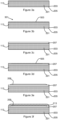
Figures 3a, 3b, 3c ,4 ,3e, & 3f are successive cross sectional views illustrating manufacturing steps, not according to the claimed invention, for the structural element offigure 2 : and -
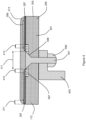
Figure 4 is a cross sectional view of a CFRP structural element of the aircraft offigure 1 , in accordance with an embodiment of the present technology. - With reference to
figure 1 , an aircraft 101 comprises a pair ofwings 103 faired into afuselage 105. Thewings 103 each carry anengine 107. The aircraft further compriseshorizontal stabilizers 109 and avertical tail plane 111 each attached at the rear of thefuselage 105. The aircraft 101 comprises structural elements that are formed from a carbon fibre reinforced plastic material (CFRP). For example, thewings 103 comprise exterior structural members in the form of wing covers 113 formed from CFRP. - The cross sectional view of
figure 2 shows an example not according to the claimed invention, in which each of the wing covers 113 comprises a compositestructural member 201 made up ofcarbon fibre layers 203 bound inmatrix layers 205 of a thermoset polymer. Asealant layer 207 substantially covers the upper surface of thewing cover 113 infigure 2 . Thesealant layer 207 is approximately 15µm to 25µm thick. Thesealant layer 207 is in the form of a polyurethane ultra-violet light (UV) resistant clear-coat varnish. - The
wing cover 113 further comprises a firstmetallic layer 209 disposed on the exterior surface of thewing cover 113 over thesealant layer 207. The extent of the firstmetallic layer 209 is limited to within the extent of thesealant layer 207. In other words, the firstmetallic layer 209 extends to within apredetermined distance 211 of the edge of thesealant layer 207 on which it is disposed. In the present example, the predetermined distance is 10mm. In the present example, the firstmetallic layer 209 comprises a 15µm thick layer of aluminium that is applied by a thermal spray deposition method. Aluminium is highly electrically conductive and arranged to dissipate electrical charge in the surface of thewing cover 113 which may, for example, result from lightning strike or static build-up. Apaint system 213 is provided on thewing cover 113 over the exposed surfaces of thesealant layer 207 and the firstmetallic layer 209. Thepaint system 213 provides environmental protection for the firstmetallic layer 209 in addition to its aesthetic effects for thewing cover 113. - The
sealant layer 207 provides an improved bonding substrate for the firstmetallic layer 209 when compared to bare composite material. Thesealant layer 207 further enables an electrical bonding function to be provided without the need for additional layers of matrix or compatible plies in the surface of the composite material. Thesealant layer 207 also seals or covers any exposed carbon fibers in the surface of the composite material. The improved bonding performance provided by thesealant layer 207 further improves the ability of the conductive firstmetallic layer 209 to electrically bond with other conductive elements so as to effectively conduct or dissipate electrical charge present in the firstmetallic layer 209. - The
sealant layer 207 also serves to reduce the risk of galvanic corrosion of the firstmetallic layer 209 by electrically insulating the firstmetallic layer 209 from thecarbon fibre 203 in the surface of thewing cover 113. For example, if thesealant layer 207 were absent and thepaint system 213 became damaged, electrical contact between thecarbon fibre 203 and the exposed firstmetallic layer 209 may result in galvanic corrosion of the firstmetallic layer 209 and deterioration of thepaint system 213 as the corrosion tracks underneath thepaint system 213. If more significant damage occurs that exposes the carbon fibre, with thesealant layer 207 present, galvanic corrosion is limited to the locality of the damage and the speed and extent of the tracking of the corrosion under thepaint system 213 is reduced. This effect thereby reduces the urgency of damage repair. - In use, the presence of the
sealant layer 207 results in a significant reduction of the erosion of the exterior surface of thepaint system 213. In use, the resilient flexure of thesealant layer 207 improves the ability of the paint system to resist erosion from soft or hard particle impact. - A method for manufacturing the composite structure of
figure 2 will now be described with reference tofigure 3a to 3f . Infigure 3a , thewing cover 113 is formed using known composite material forming techniques to lay up layers ofcarbon fibre 203 preimpregnated withmatrix material 205 in the form of thermosetting polymer resin. Thewing cover 113 is then heated in an autoclave to cure the CFRP material. With reference tofigure 3b , a first keying process is applied to theexterior surface 301 of thewing cover 113 to provide asurface key 303 to aid adhesion of the subsequent layer. In the present embodiment, the keying process is grit blasting. With reference tofigure 3c , thesealant layer 207 is applied to theupper surface 301 substantially covering thewhole surface 301. In the present example, thesealant layer 207 comprises a polyurethane material with a finished thickness of up to 15µm to 35µm and is applied by spraying. With reference tofigure 3d , a second keying process is applied to the exterior surface of thesealant layer 207 to provide asecond surface key 305 to aid adhesion of subsequent layers. With reference tofigure 3e , the firstmetallic layer 209 is applied to the upper surface of thesealant layer 207 up to thepredetermined distance 211 from the edges of thesealant layer 207. In the present example, the firstmetallic layer 209 comprises aluminium with a thickness of up to 15µm and is applied by thermal spraying. With reference tofigure 3f , thepaint system 213 is then applied to the exposed respective upper surfaces of thesealant layer 207 and the firstmetallic layer 209. In the present example, thepaint system 213 comprises a primer coat and one or more top coats (not shown separately). - An embodiment of the present technology according to the invention will now be described with reference to the cross sectional view of
figure 4 . Infigure 4 , where parts are substantially common to a previously described example, the same reference numbers are used in order to assist in understanding. In the present embodiment, a row of fasteners 401 (only one shown) fix thewing cover 113 along astructural member 403 in the form of a spar of thewing 103. In the present embodiment, thespar 403 is formed from aluminium. Thefasteners 401, in the form of swaged fasteners, are fixed in place by respective swagedcollars 405. Thewing cover 113 in the present embodiment, further comprises a secondmetallic layer 407 in the form of an expanded copper foil (ECF) strip. TheECF strip 407 is integrally formed in the upper surface of thewing cover 113. Thefasteners 401 are fixed through afastener region 411 located generally centrally widthwise along theECF strip 407. In the present embodiment, thefasteners 401 are formed from a titanium alloy and fixed onto thealuminium spar 403 resulting in an electrically conductive path between the outside and the inside of thewing cover 113. - In the present embodiment, the
sealant layer 207 extends over the outer surface of thewing cover 113 up to the edge of theholes 409 for thefasteners 401. The firstmetallic layer 209 on thesealant layer 207 extends over the edge of theECF strip 407 so as to form anoverlap 413 of a predetermined width configured to provide electrical continuity between the firstmetallic layer 209 and theECF strip 407. In the present embodiment, theoverlap 413 has a width of at least 10mm. The edge of the firstmetallic layer 209 is spaced apredetermined distance 415 from thefastener region 411 of theECF strip 407. Thepredetermined distance 415 is configured so as to reduce the probability of galvanic corrosion in response to electrical continuity between the firstmetallic layer 209 and thefastener 401 enabled by a failure in thepaint system 213 adjacent thehead 401. In the present embodiment, the predetermined distance is 10mm. - The method of manufacturing the composite structure of
figure 4 according to the invention will now be described by way of the additional steps to the method described above with reference tofigures 3a to 3f . In the first step described with reference tofigure 3a above, the secondmetallic layer 407 in the form of the ECF strip is integrally formed with the compositestructural member 201 in the form of thewing cover 113. Steps 3b, 3c and 3d are then performed as described above. After the step described with respect tofigure 3d , theholes 409 are drilled through thewing cover 113 and spar 403 and thefasteners 401 fitted so as to fix thewing cover 113 to thespar 403. In step 3e, prior to the firstmetallic layer 209 being applied thefastener region 411 and thepredetermined spacing 415 either side is masked. After the firstmetallic layer 209 has been applied the masking is removed leaving a gap in the firstmetallic layer 209 corresponding to thefastener region 411 and the adjacentpredetermined spacings 415. Thepaint system 213 is then applied as described with reference tofigure 3f . - In another embodiment, prior to the application of the
sealant layer 207 thefastener region 411 is masked. After thesealant layer 207 has been applied the masking is removed leaving thefastener region 411 free of thesealant layer 207. In a further embodiment, the sealant layer is applied over the drilledholes 409 or over the fittedfasteners 401 without masking resultingsealant layer 207 extending into theholes 409 or over the heads of thefasteners 401. - In another embodiment, the first
metallic layer 209 is applied prior to the drilling of theholes 409 or prior to the fitting of thefasteners 401. - As will be understood by those skilled in the art, the
fasteners 401 may be sleeved fasteners to ensure full electrical bonding between thefasteners 401 and thewing cover 113 and spar 403 or nut caps may be used which are configured to contain outgassing of plasma resulting from arcing between thefasteners 401 and thewing cover 113 andspar 403. - In another embodiment, the
sealant layer 207 is up to 50µm thick. In another embodiment of the technology, the firstmetallic layer 209 is up to 25µm thick. In a further embodiment of the technology, the firstmetallic layer 209 is up to 50µm thick. - As will be understood by those skilled in the art, the sealant layer may be formed from any suitable sealant material. The sealant may be solvent based, an emulsion where the carrier may be water based, thermosetting or thermoplastic or a chemically setting material such as an epoxy system. The sealant may be applied by any suitable deposition technique such as spraying, painting or vapour deposition.
- As will be understood by those skilled in the art, the keying technique is not limited to grit blasting as described above but keying may be achieved by any other suitable method of roughening or ablating a surface. Examples of possible suitable techniques include the application of a mechanical tool or material, chemical etching, the inclusion of a sacrificial peel ply in the surface of the composite material, laser ablation or other non-intrusive keying techniques or processes. As will be understood by those skilled in the art, in some applications, keying techniques may not be necessary where the surface of the composite material provides a surface to which the sealant layer adheres to an acceptable degree for the given application.
- As will be understood by those skilled in the art, the first or second metallic layers may be formed from any other suitable metal such as copper or silver or zinc or nickel. The first or second metallic layers may be disposed on the structural member by any suitable means not limited to thermal spray, for example, cold metal spray, plasma or vapour deposition, additive manufacturing or printing.
- As will be understood by those skilled in the art, the second metallic layer may be formed from any suitable metal formed in any suitable format. For example, bronze mesh may be used as one alternative to ECF.
- As will be understood by those skilled in the art, the technology described herein is not limited in application to any particular structure but may be applied to any structure of an aircraft. As will be understood by those skilled in the art, the present technology may be applied to any type of structure, including automotive, space, maritime or civil engineering structures, where a conductive exterior layer is affixed to a composite structural element. The technology may be applied to a selected part or substantially the whole of any such structure.
- As will be understood by those skilled in the art, the whole or a selected part or layer of the structure in accordance with the technology described herein may be constructed using additive layer manufacturing (ALM) techniques or three-dimension printing (3DP) techniques. For example, the sealant or metallic layers may be applied to a composite part by ALM or 3DP.
Claims (12)
- A composite structure comprising:a composite structural member (201) formed from a synthetic composite material;a sealant layer (207) disposed on a surface of the composite structural member (201);a first metallic layer (209) disposed on the sealant layer (207); and characterized bya second metallic layer (407) disposed in or on a surface of the composite structural member (201), wherein the first metallic layer (209) overlaps the second metallic layer (407); andwherein the sealant layer (207) is configured with an overlap of the second metallic layer (407).
- A composite structure according to claim 1 in which the sealant layer (207) is discrete from the composite structural member (201).
- A composite structure according to any preceding claim in which the sealant layer (207) is resiliently deformable.
- A composite structural member according to any preceding claim in which the sealant layer (207) comprises one or more polyurethanes.
- A composite structure according to any preceding claim in which the sealant layer (207) is configured as a barrier between the composite structural member (201) and the first metallic layer (209).
- A composite structure according to any preceding claim in which the extent of the first metallic layer (209) is restricted to within a predetermined distance (211) of an edge of the composite structural member (201).
- A composite structure according to any preceding claim in which the first metallic layer (209) comprises a thermally applied metal film.
- A composite structure according to any preceding claim in which the overlap (413) of the first metallic layer (209) over the second metallic layer (407) is configured to provide electrical continuity between the first metallic layer (209) and the second metallic layer (407).
- A composite structure according to any preceding claim, in which the overlap of the sealant layer (207) over the second metallic layer (407) is substantially equal to or greater than the overlap of the first metallic layer (209) over the second metallic layer (407).
- A composite structure according to any preceding claim in which the overlap (413) of the second metallic layer (407) and the first metallic layer (209) has a generally uniform width.
- A composite structure according to any preceding claim in which the second metallic layer (407) comprises a fastener region (411) in which one or more fasteners may be located and the extent of the first metallic layer (209) is spaced from the fastener region by a predetermined distance (415)
- A method for forming a composite structure comprising the steps of:forming a composite structural member (201) from a synthetic composite material;disposing a sealant layer (207) on a surface of the composite structural member;disposing a first metallic layer (209) on the sealant layer; characterized by disposinga second metallic layer (407) in or on a surface of the composite structural member, wherein the first and second metallic layers (209, 407) are configured to overlap; andconfiguring the sealant layer (207) with an overlap of the second metallic layer (407).
Applications Claiming Priority (2)
| Application Number | Priority Date | Filing Date | Title |
|---|---|---|---|
| GB1522426.4A GB2545494A (en) | 2015-12-18 | 2015-12-18 | A structure formed from composite material |
| GB1617999.6A GB2545543A (en) | 2015-12-18 | 2016-10-25 | A structure formed from composite material |
Publications (2)
| Publication Number | Publication Date |
|---|---|
| EP3208080A1 EP3208080A1 (en) | 2017-08-23 |
| EP3208080B1 true EP3208080B1 (en) | 2024-07-03 |
Family
ID=55311257
Family Applications (1)
| Application Number | Title | Priority Date | Filing Date |
|---|---|---|---|
| EP16201817.0A Active EP3208080B1 (en) | 2015-12-18 | 2016-12-01 | A structure formed from composite material |
Country Status (3)
| Country | Link |
|---|---|
| US (1) | US10167074B2 (en) |
| EP (1) | EP3208080B1 (en) |
| GB (2) | GB2545494A (en) |
Families Citing this family (6)
| Publication number | Priority date | Publication date | Assignee | Title |
|---|---|---|---|---|
| US11085111B2 (en) * | 2018-10-11 | 2021-08-10 | The Boeing Company | Laminate composite structural components and methods for the same |
| CN111070722B (en) * | 2018-10-19 | 2021-10-22 | 哈尔滨工业大学 | A kind of preparation method of lightning protection composite material based on heat insulation and insulation mechanism |
| CN109738489B (en) * | 2018-12-06 | 2023-12-29 | 西安交通大学 | Calculation method of damage to carbon fiber composite materials under the action of multiple continuous lightning current components |
| CN109732944A (en) * | 2019-01-12 | 2019-05-10 | 航天神舟飞行器有限公司 | A kind of aviation laminated board type wing manufacturing process |
| US11884055B2 (en) * | 2019-03-26 | 2024-01-30 | The Boeing Company | Laminated hybrid metallized polymer films, system, and method for erosion protection of composite structures |
| CN121268302B (en) * | 2025-12-08 | 2026-03-10 | 西安爱邦电磁技术有限责任公司 | Composite rotor wing with electrostatic discharge function, preparation method and discharge method |
Family Cites Families (6)
| Publication number | Priority date | Publication date | Assignee | Title |
|---|---|---|---|---|
| ES2428032T3 (en) * | 2003-09-30 | 2013-11-05 | The Boeing Company | Protective wall covering and use thereof |
| US7277266B1 (en) * | 2006-03-29 | 2007-10-02 | The Boeing Company | Lightning protection system for composite structure |
| DE102007019716A1 (en) * | 2007-04-26 | 2008-10-30 | Airbus Deutschland Gmbh | Fiber metal laminate panel |
| US7883050B2 (en) * | 2007-06-28 | 2011-02-08 | The Boeing Company | Composites with integrated multi-functional circuits |
| US7835130B2 (en) * | 2007-10-05 | 2010-11-16 | The Boeing Company | Method and apparatus for lightning protection of a composite structure |
| US9221547B2 (en) * | 2010-06-25 | 2015-12-29 | The Boeing Company | Static dissipative fuel tank coatings and methods |
-
2015
- 2015-12-18 GB GB1522426.4A patent/GB2545494A/en not_active Withdrawn
-
2016
- 2016-10-25 GB GB1617999.6A patent/GB2545543A/en not_active Withdrawn
- 2016-12-01 EP EP16201817.0A patent/EP3208080B1/en active Active
- 2016-12-16 US US15/381,946 patent/US10167074B2/en active Active
Also Published As
| Publication number | Publication date |
|---|---|
| GB201522426D0 (en) | 2016-02-03 |
| US20170174312A1 (en) | 2017-06-22 |
| GB2545494A (en) | 2017-06-21 |
| EP3208080A1 (en) | 2017-08-23 |
| GB2545543A (en) | 2017-06-21 |
| GB201617999D0 (en) | 2016-12-07 |
| US10167074B2 (en) | 2019-01-01 |
Similar Documents
| Publication | Publication Date | Title |
|---|---|---|
| US10167074B2 (en) | Structure formed from composite material | |
| US7277266B1 (en) | Lightning protection system for composite structure | |
| US7867621B2 (en) | Wide area lightning diverter overlay | |
| EP1935784B1 (en) | Flex circuit lightning protection appliqué system for skin fasteners in composite structures | |
| CA2934731C (en) | Methods for diverting lightning current from skin fasteners in composite, non-metallic structures | |
| RU2465176C2 (en) | System for drainage of lightning current generated by lightning discharge onto aircraft | |
| EP2190742B1 (en) | Method and apparatus for lightning protection of a composite structure | |
| US4352142A (en) | Composite aircraft structure having lightning protection | |
| EP1772376B1 (en) | Fastener | |
| CA2677311C (en) | Aircraft assembly and method for manufacturing the same | |
| JP2011524265A (en) | Integrated lightning protection material creation system and method | |
| US10982332B2 (en) | Method of manufacturing a structural arrangement with a fiber reinforced polymer component and a cold gas sprayed electrically conductive layer | |
| EP2987562B1 (en) | Methods and apparatus for use in forming a lightning protection system | |
| US11801666B2 (en) | Structure formed from composite material | |
| US10507491B2 (en) | Rotary wing aircraft with a structural arrangement that comprises an electrically conductive connection |
Legal Events
| Date | Code | Title | Description |
|---|---|---|---|
| PUAI | Public reference made under article 153(3) epc to a published international application that has entered the european phase |
Free format text: ORIGINAL CODE: 0009012 |
|
| STAA | Information on the status of an ep patent application or granted ep patent |
Free format text: STATUS: THE APPLICATION HAS BEEN PUBLISHED |
|
| AK | Designated contracting states |
Kind code of ref document: A1 Designated state(s): AL AT BE BG CH CY CZ DE DK EE ES FI FR GB GR HR HU IE IS IT LI LT LU LV MC MK MT NL NO PL PT RO RS SE SI SK SM TR |
|
| AX | Request for extension of the european patent |
Extension state: BA ME |
|
| STAA | Information on the status of an ep patent application or granted ep patent |
Free format text: STATUS: REQUEST FOR EXAMINATION WAS MADE |
|
| 17P | Request for examination filed |
Effective date: 20180221 |
|
| RBV | Designated contracting states (corrected) |
Designated state(s): AL AT BE BG CH CY CZ DE DK EE ES FI FR GB GR HR HU IE IS IT LI LT LU LV MC MK MT NL NO PL PT RO RS SE SI SK SM TR |
|
| STAA | Information on the status of an ep patent application or granted ep patent |
Free format text: STATUS: EXAMINATION IS IN PROGRESS |
|
| 17Q | First examination report despatched |
Effective date: 20210325 |
|
| GRAP | Despatch of communication of intention to grant a patent |
Free format text: ORIGINAL CODE: EPIDOSNIGR1 |
|
| STAA | Information on the status of an ep patent application or granted ep patent |
Free format text: STATUS: GRANT OF PATENT IS INTENDED |
|
| INTG | Intention to grant announced |
Effective date: 20230119 |
|
| GRAJ | Information related to disapproval of communication of intention to grant by the applicant or resumption of examination proceedings by the epo deleted |
Free format text: ORIGINAL CODE: EPIDOSDIGR1 |
|
| STAA | Information on the status of an ep patent application or granted ep patent |
Free format text: STATUS: EXAMINATION IS IN PROGRESS |
|
| INTC | Intention to grant announced (deleted) | ||
| GRAP | Despatch of communication of intention to grant a patent |
Free format text: ORIGINAL CODE: EPIDOSNIGR1 |
|
| STAA | Information on the status of an ep patent application or granted ep patent |
Free format text: STATUS: GRANT OF PATENT IS INTENDED |
|
| INTG | Intention to grant announced |
Effective date: 20230630 |
|
| GRAJ | Information related to disapproval of communication of intention to grant by the applicant or resumption of examination proceedings by the epo deleted |
Free format text: ORIGINAL CODE: EPIDOSDIGR1 |
|
| STAA | Information on the status of an ep patent application or granted ep patent |
Free format text: STATUS: EXAMINATION IS IN PROGRESS |
|
| INTC | Intention to grant announced (deleted) | ||
| GRAP | Despatch of communication of intention to grant a patent |
Free format text: ORIGINAL CODE: EPIDOSNIGR1 |
|
| STAA | Information on the status of an ep patent application or granted ep patent |
Free format text: STATUS: GRANT OF PATENT IS INTENDED |
|
| INTG | Intention to grant announced |
Effective date: 20240207 |
|
| GRAS | Grant fee paid |
Free format text: ORIGINAL CODE: EPIDOSNIGR3 |
|
| GRAA | (expected) grant |
Free format text: ORIGINAL CODE: 0009210 |
|
| STAA | Information on the status of an ep patent application or granted ep patent |
Free format text: STATUS: THE PATENT HAS BEEN GRANTED |
|
| AK | Designated contracting states |
Kind code of ref document: B1 Designated state(s): AL AT BE BG CH CY CZ DE DK EE ES FI FR GB GR HR HU IE IS IT LI LT LU LV MC MK MT NL NO PL PT RO RS SE SI SK SM TR |
|
| REG | Reference to a national code |
Ref country code: CH Ref legal event code: EP |
|
| REG | Reference to a national code |
Ref country code: DE Ref legal event code: R096 Ref document number: 602016088202 Country of ref document: DE |
|
| REG | Reference to a national code |
Ref country code: LT Ref legal event code: MG9D |
|
| REG | Reference to a national code |
Ref country code: NL Ref legal event code: MP Effective date: 20240703 |
|
| PG25 | Lapsed in a contracting state [announced via postgrant information from national office to epo] |
Ref country code: PT Free format text: LAPSE BECAUSE OF FAILURE TO SUBMIT A TRANSLATION OF THE DESCRIPTION OR TO PAY THE FEE WITHIN THE PRESCRIBED TIME-LIMIT Effective date: 20241104 |
|
| REG | Reference to a national code |
Ref country code: AT Ref legal event code: MK05 Ref document number: 1699414 Country of ref document: AT Kind code of ref document: T Effective date: 20240703 |
|
| PG25 | Lapsed in a contracting state [announced via postgrant information from national office to epo] |
Ref country code: NL Free format text: LAPSE BECAUSE OF FAILURE TO SUBMIT A TRANSLATION OF THE DESCRIPTION OR TO PAY THE FEE WITHIN THE PRESCRIBED TIME-LIMIT Effective date: 20240703 |
|
| PG25 | Lapsed in a contracting state [announced via postgrant information from national office to epo] |
Ref country code: PT Free format text: LAPSE BECAUSE OF FAILURE TO SUBMIT A TRANSLATION OF THE DESCRIPTION OR TO PAY THE FEE WITHIN THE PRESCRIBED TIME-LIMIT Effective date: 20241104 Ref country code: NL Free format text: LAPSE BECAUSE OF FAILURE TO SUBMIT A TRANSLATION OF THE DESCRIPTION OR TO PAY THE FEE WITHIN THE PRESCRIBED TIME-LIMIT Effective date: 20240703 |
|
| PG25 | Lapsed in a contracting state [announced via postgrant information from national office to epo] |
Ref country code: NO Free format text: LAPSE BECAUSE OF FAILURE TO SUBMIT A TRANSLATION OF THE DESCRIPTION OR TO PAY THE FEE WITHIN THE PRESCRIBED TIME-LIMIT Effective date: 20241003 |
|
| PG25 | Lapsed in a contracting state [announced via postgrant information from national office to epo] |
Ref country code: PL Free format text: LAPSE BECAUSE OF FAILURE TO SUBMIT A TRANSLATION OF THE DESCRIPTION OR TO PAY THE FEE WITHIN THE PRESCRIBED TIME-LIMIT Effective date: 20240703 Ref country code: FI Free format text: LAPSE BECAUSE OF FAILURE TO SUBMIT A TRANSLATION OF THE DESCRIPTION OR TO PAY THE FEE WITHIN THE PRESCRIBED TIME-LIMIT Effective date: 20240703 Ref country code: GR Free format text: LAPSE BECAUSE OF FAILURE TO SUBMIT A TRANSLATION OF THE DESCRIPTION OR TO PAY THE FEE WITHIN THE PRESCRIBED TIME-LIMIT Effective date: 20241004 |
|
| PG25 | Lapsed in a contracting state [announced via postgrant information from national office to epo] |
Ref country code: BG Free format text: LAPSE BECAUSE OF FAILURE TO SUBMIT A TRANSLATION OF THE DESCRIPTION OR TO PAY THE FEE WITHIN THE PRESCRIBED TIME-LIMIT Effective date: 20240703 |
|
| PG25 | Lapsed in a contracting state [announced via postgrant information from national office to epo] |
Ref country code: LV Free format text: LAPSE BECAUSE OF FAILURE TO SUBMIT A TRANSLATION OF THE DESCRIPTION OR TO PAY THE FEE WITHIN THE PRESCRIBED TIME-LIMIT Effective date: 20240703 |
|
| PG25 | Lapsed in a contracting state [announced via postgrant information from national office to epo] |
Ref country code: IS Free format text: LAPSE BECAUSE OF FAILURE TO SUBMIT A TRANSLATION OF THE DESCRIPTION OR TO PAY THE FEE WITHIN THE PRESCRIBED TIME-LIMIT Effective date: 20241103 Ref country code: AT Free format text: LAPSE BECAUSE OF FAILURE TO SUBMIT A TRANSLATION OF THE DESCRIPTION OR TO PAY THE FEE WITHIN THE PRESCRIBED TIME-LIMIT Effective date: 20240703 |
|
| PG25 | Lapsed in a contracting state [announced via postgrant information from national office to epo] |
Ref country code: CZ Free format text: LAPSE BECAUSE OF FAILURE TO SUBMIT A TRANSLATION OF THE DESCRIPTION OR TO PAY THE FEE WITHIN THE PRESCRIBED TIME-LIMIT Effective date: 20240703 Ref country code: HR Free format text: LAPSE BECAUSE OF FAILURE TO SUBMIT A TRANSLATION OF THE DESCRIPTION OR TO PAY THE FEE WITHIN THE PRESCRIBED TIME-LIMIT Effective date: 20240703 |
|
| PG25 | Lapsed in a contracting state [announced via postgrant information from national office to epo] |
Ref country code: ES Free format text: LAPSE BECAUSE OF FAILURE TO SUBMIT A TRANSLATION OF THE DESCRIPTION OR TO PAY THE FEE WITHIN THE PRESCRIBED TIME-LIMIT Effective date: 20240703 Ref country code: RS Free format text: LAPSE BECAUSE OF FAILURE TO SUBMIT A TRANSLATION OF THE DESCRIPTION OR TO PAY THE FEE WITHIN THE PRESCRIBED TIME-LIMIT Effective date: 20241003 |
|
| PG25 | Lapsed in a contracting state [announced via postgrant information from national office to epo] |
Ref country code: RS Free format text: LAPSE BECAUSE OF FAILURE TO SUBMIT A TRANSLATION OF THE DESCRIPTION OR TO PAY THE FEE WITHIN THE PRESCRIBED TIME-LIMIT Effective date: 20241003 Ref country code: PL Free format text: LAPSE BECAUSE OF FAILURE TO SUBMIT A TRANSLATION OF THE DESCRIPTION OR TO PAY THE FEE WITHIN THE PRESCRIBED TIME-LIMIT Effective date: 20240703 Ref country code: NO Free format text: LAPSE BECAUSE OF FAILURE TO SUBMIT A TRANSLATION OF THE DESCRIPTION OR TO PAY THE FEE WITHIN THE PRESCRIBED TIME-LIMIT Effective date: 20241003 Ref country code: LV Free format text: LAPSE BECAUSE OF FAILURE TO SUBMIT A TRANSLATION OF THE DESCRIPTION OR TO PAY THE FEE WITHIN THE PRESCRIBED TIME-LIMIT Effective date: 20240703 Ref country code: IS Free format text: LAPSE BECAUSE OF FAILURE TO SUBMIT A TRANSLATION OF THE DESCRIPTION OR TO PAY THE FEE WITHIN THE PRESCRIBED TIME-LIMIT Effective date: 20241103 Ref country code: HR Free format text: LAPSE BECAUSE OF FAILURE TO SUBMIT A TRANSLATION OF THE DESCRIPTION OR TO PAY THE FEE WITHIN THE PRESCRIBED TIME-LIMIT Effective date: 20240703 Ref country code: GR Free format text: LAPSE BECAUSE OF FAILURE TO SUBMIT A TRANSLATION OF THE DESCRIPTION OR TO PAY THE FEE WITHIN THE PRESCRIBED TIME-LIMIT Effective date: 20241004 Ref country code: FI Free format text: LAPSE BECAUSE OF FAILURE TO SUBMIT A TRANSLATION OF THE DESCRIPTION OR TO PAY THE FEE WITHIN THE PRESCRIBED TIME-LIMIT Effective date: 20240703 Ref country code: ES Free format text: LAPSE BECAUSE OF FAILURE TO SUBMIT A TRANSLATION OF THE DESCRIPTION OR TO PAY THE FEE WITHIN THE PRESCRIBED TIME-LIMIT Effective date: 20240703 Ref country code: CZ Free format text: LAPSE BECAUSE OF FAILURE TO SUBMIT A TRANSLATION OF THE DESCRIPTION OR TO PAY THE FEE WITHIN THE PRESCRIBED TIME-LIMIT Effective date: 20240703 Ref country code: BG Free format text: LAPSE BECAUSE OF FAILURE TO SUBMIT A TRANSLATION OF THE DESCRIPTION OR TO PAY THE FEE WITHIN THE PRESCRIBED TIME-LIMIT Effective date: 20240703 Ref country code: AT Free format text: LAPSE BECAUSE OF FAILURE TO SUBMIT A TRANSLATION OF THE DESCRIPTION OR TO PAY THE FEE WITHIN THE PRESCRIBED TIME-LIMIT Effective date: 20240703 |
|
| REG | Reference to a national code |
Ref country code: DE Ref legal event code: R097 Ref document number: 602016088202 Country of ref document: DE |
|
| PG25 | Lapsed in a contracting state [announced via postgrant information from national office to epo] |
Ref country code: DK Free format text: LAPSE BECAUSE OF FAILURE TO SUBMIT A TRANSLATION OF THE DESCRIPTION OR TO PAY THE FEE WITHIN THE PRESCRIBED TIME-LIMIT Effective date: 20240703 Ref country code: RO Free format text: LAPSE BECAUSE OF FAILURE TO SUBMIT A TRANSLATION OF THE DESCRIPTION OR TO PAY THE FEE WITHIN THE PRESCRIBED TIME-LIMIT Effective date: 20240703 Ref country code: SM Free format text: LAPSE BECAUSE OF FAILURE TO SUBMIT A TRANSLATION OF THE DESCRIPTION OR TO PAY THE FEE WITHIN THE PRESCRIBED TIME-LIMIT Effective date: 20240703 |
|
| PG25 | Lapsed in a contracting state [announced via postgrant information from national office to epo] |
Ref country code: EE Free format text: LAPSE BECAUSE OF FAILURE TO SUBMIT A TRANSLATION OF THE DESCRIPTION OR TO PAY THE FEE WITHIN THE PRESCRIBED TIME-LIMIT Effective date: 20240703 |
|
| PG25 | Lapsed in a contracting state [announced via postgrant information from national office to epo] |
Ref country code: IT Free format text: LAPSE BECAUSE OF FAILURE TO SUBMIT A TRANSLATION OF THE DESCRIPTION OR TO PAY THE FEE WITHIN THE PRESCRIBED TIME-LIMIT Effective date: 20240703 Ref country code: SK Free format text: LAPSE BECAUSE OF FAILURE TO SUBMIT A TRANSLATION OF THE DESCRIPTION OR TO PAY THE FEE WITHIN THE PRESCRIBED TIME-LIMIT Effective date: 20240703 |
|
| PLBE | No opposition filed within time limit |
Free format text: ORIGINAL CODE: 0009261 |
|
| STAA | Information on the status of an ep patent application or granted ep patent |
Free format text: STATUS: NO OPPOSITION FILED WITHIN TIME LIMIT |
|
| 26N | No opposition filed |
Effective date: 20250404 |
|
| REG | Reference to a national code |
Ref country code: DE Ref legal event code: R119 Ref document number: 602016088202 Country of ref document: DE |
|
| PG25 | Lapsed in a contracting state [announced via postgrant information from national office to epo] |
Ref country code: MC Free format text: LAPSE BECAUSE OF FAILURE TO SUBMIT A TRANSLATION OF THE DESCRIPTION OR TO PAY THE FEE WITHIN THE PRESCRIBED TIME-LIMIT Effective date: 20240703 |
|
| REG | Reference to a national code |
Ref country code: CH Ref legal event code: PL |
|
| PG25 | Lapsed in a contracting state [announced via postgrant information from national office to epo] |
Ref country code: LU Free format text: LAPSE BECAUSE OF NON-PAYMENT OF DUE FEES Effective date: 20241201 |
|
| PG25 | Lapsed in a contracting state [announced via postgrant information from national office to epo] |
Ref country code: SE Free format text: LAPSE BECAUSE OF FAILURE TO SUBMIT A TRANSLATION OF THE DESCRIPTION OR TO PAY THE FEE WITHIN THE PRESCRIBED TIME-LIMIT Effective date: 20240703 |
|
| PG25 | Lapsed in a contracting state [announced via postgrant information from national office to epo] |
Ref country code: DE Free format text: LAPSE BECAUSE OF NON-PAYMENT OF DUE FEES Effective date: 20250701 |
|
| PG25 | Lapsed in a contracting state [announced via postgrant information from national office to epo] |
Ref country code: CH Free format text: LAPSE BECAUSE OF NON-PAYMENT OF DUE FEES Effective date: 20241231 |
|
| PG25 | Lapsed in a contracting state [announced via postgrant information from national office to epo] |
Ref country code: IE Free format text: LAPSE BECAUSE OF NON-PAYMENT OF DUE FEES Effective date: 20241201 |
|
| PGFP | Annual fee paid to national office [announced via postgrant information from national office to epo] |
Ref country code: GB Payment date: 20251219 Year of fee payment: 10 |
|
| PGFP | Annual fee paid to national office [announced via postgrant information from national office to epo] |
Ref country code: FR Payment date: 20251223 Year of fee payment: 10 |
|
| PGFP | Annual fee paid to national office [announced via postgrant information from national office to epo] |
Ref country code: BE Payment date: 20251219 Year of fee payment: 10 |
|
| PG25 | Lapsed in a contracting state [announced via postgrant information from national office to epo] |
Ref country code: CY Free format text: LAPSE BECAUSE OF FAILURE TO SUBMIT A TRANSLATION OF THE DESCRIPTION OR TO PAY THE FEE WITHIN THE PRESCRIBED TIME-LIMIT; INVALID AB INITIO Effective date: 20161201 |